Those of us who have small garages know the frustration of parking a little bit too far in or a little too far out and not being able to walk around the vehicle. We recently bought a larger vehicle, and it has to be parked perfectly in the garage to walk around the front and back. So here is an Arduino based parking assistant to help you park in exactly the same spot every time.
This project assumes you know the basics of Arduino programming, otherwise read our article on getting started with Arduino.
What You Will Need To Build An Arduino Parking Assistant
Materials:
- 1x 2×4 – at least 8″ long – Buy Here
- 8x Philips Screws – Preferably 1″ Long – Buy Here
- 1x Power Supply – 5 volt, 850mA – Buy Here
- 1x Arduino Pro Mini – 5 volt, 16MHz – Buy Here
- 1x HC-SR04 Ultrasonic Distance Sensor – Buy Here
- 12x 220 ohm, 1/4 watt Resistors – Buy Here
- 8x Green LEDs – 5mm – Buy Here
- 4x Red LEDs – 5mm – Buy Here
- 1x Tactile Pushbutton – 6mm – Buy Here
- 3x Four Conductor Wire Sold by the Foot – 22 gauge – Buy Here
Tools:
- Wire Stripper
- Bandsaw
- Soldering Iron
- Solder – I use 60/40 Rosin Core
- Hot Glue Gun
- Speed Square
- Stick Glue
- Philips Screwdriver
- Pencil
- Drill
- 7/64″ Drill Bit – this depends on the size of your screws
- 3/16″ Drill Bit
- 1/4″ Drill Bit
- 1″ Forstner Bit
- Computer with the Arduino IDE
- FTDI Programmer
How To Make Your Arduino Parking Assistant
Make The LED Display Box
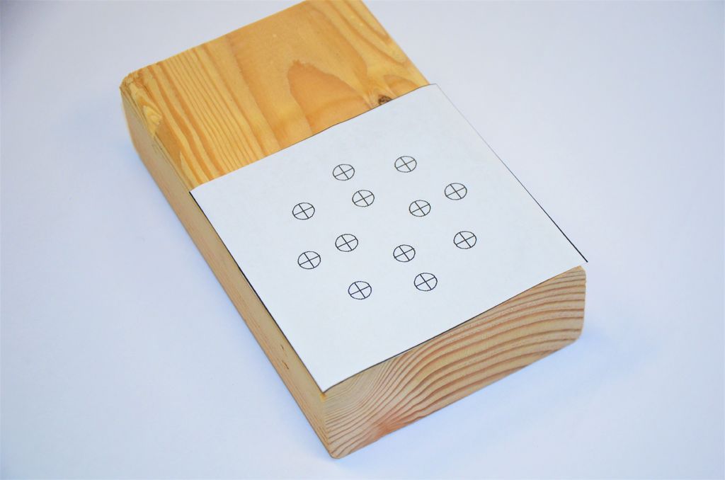
The first step in this project is to make the enclosure. Print the PDF Pattern included below. Be sure you’re set to print at 100% scale. Now cut out the pattern and glue it to the 2×4. Be careful to line it up with the edges. It’s only temporary, so only glue it lightly.
Use your bandsaw to cut the 2×4 along the edge of the pattern. You could also use a chop saw or table saw.
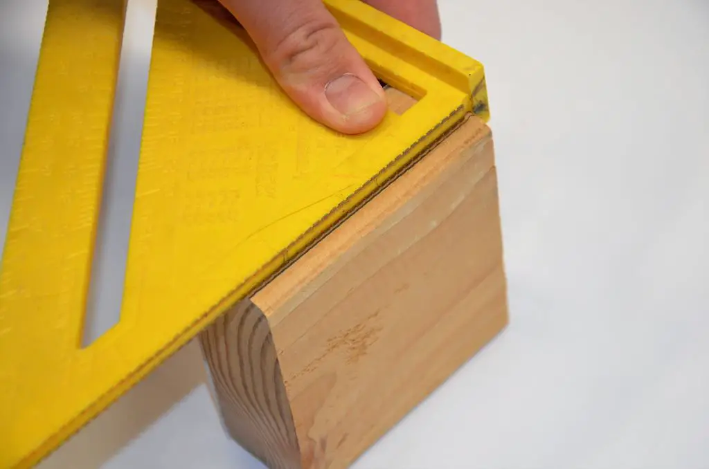
Now we need to turn this thing from a 2×4 into a box! Use your speed square to mark a line lengthwise on the side of the 2×4 about a quarter of an inch from the back of the box.
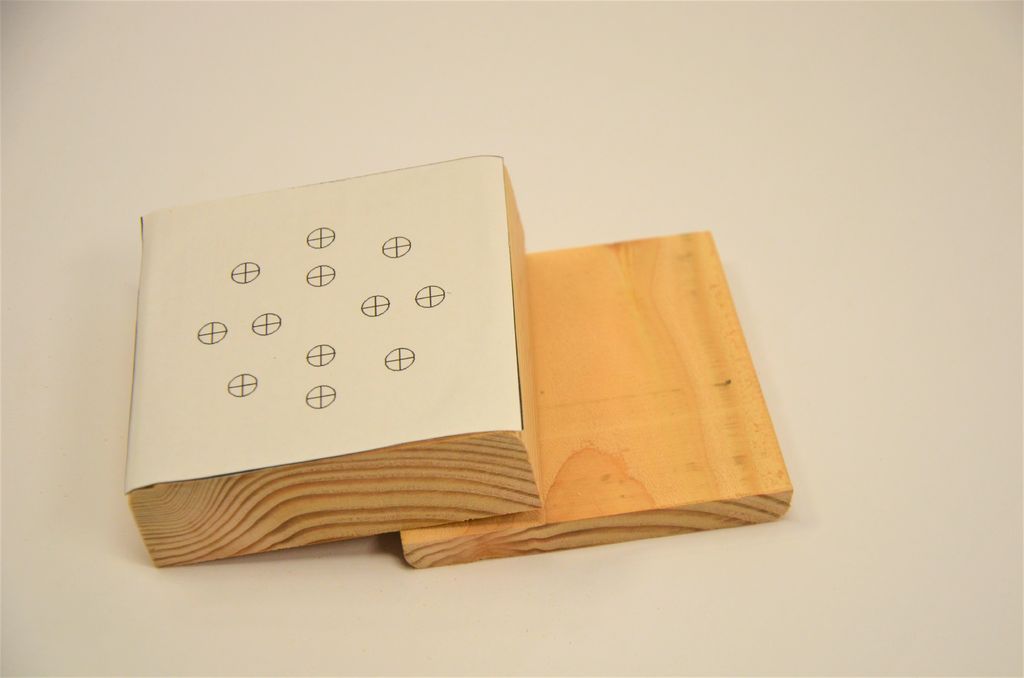
Go back to the bandsaw and cut directly on the line. This will cut a separate piece that will become our lid. You’ll be cutting close to your fingers; Please be careful!
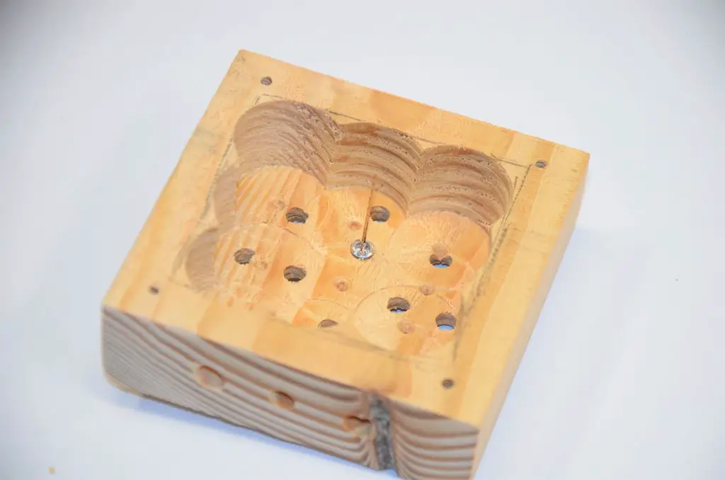
Using your pencil, mark a rough square on the back of the larger block about a half inch from all the edges.

Now use your 1-inch to drill bore out the rectangle. You need to drill as deep as possible without coming through the front. Don’t drill too deep!

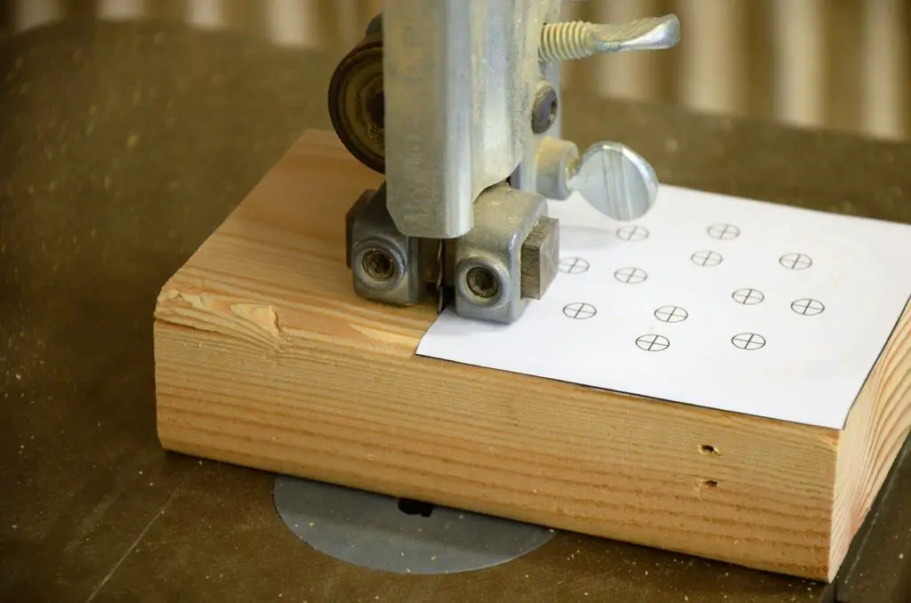
Chock up your 3/16 inch drill bit and carefully drill each of the holes marked on the front of the pattern. I found it works best if you make a small indention with an awl before you drill.
Next drill a 3/16 inch hole roughly in the center of the bottom. This will be the hole for your calibration button.
Now use your 1/4 inch drill bit to drill two more holes in the bottom. These will be the holes for the wires.
Now you’re done using the pattern. Peel it off as cleanly as possible.
Take the lid and lay it on the bottom. Turn it around if you have to, you need it in the original orientation.
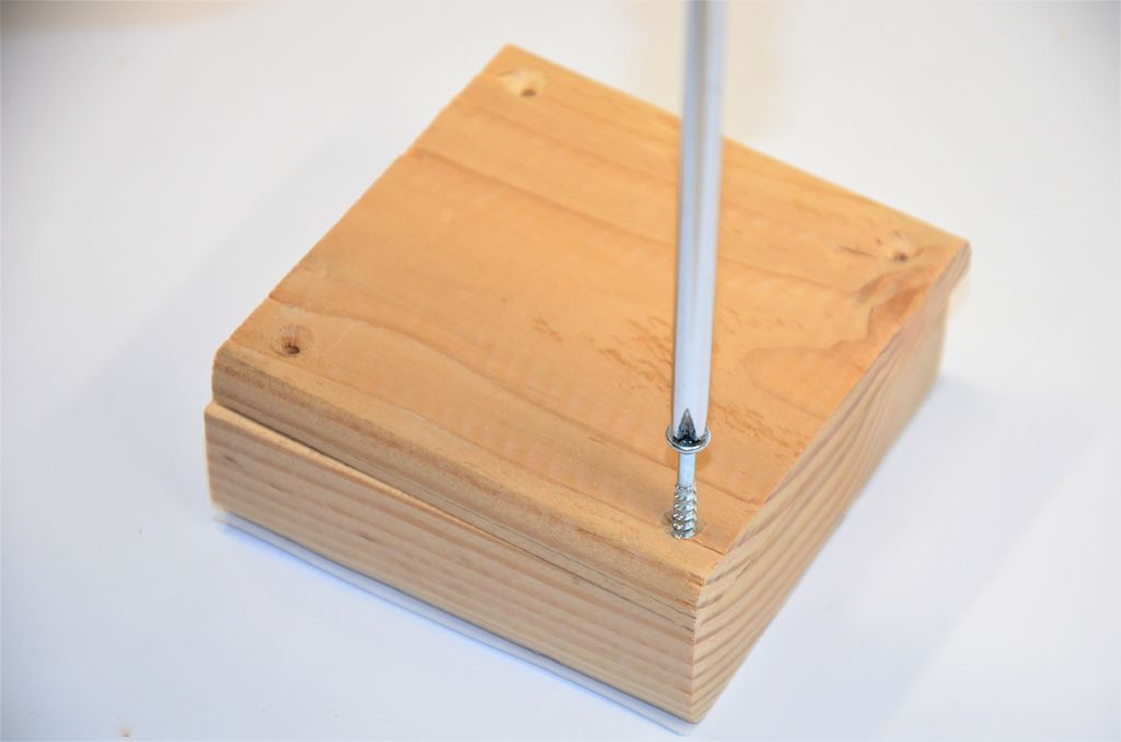
Next use the 7/64 drill bit to drill a hole about a quarter of an inch from each corner. Drill about a quarter of an inch deep; don’t drill through the front!
Use the screwdriver and screws to fasten the lid.
You don’t have to, but it makes the box look a whole lot better if you give it a good, through sanding.
Add Electronics To The LED Display Box
The LEDs should be arranged in two rings; a large green ring on the outside with a smaller red ring inside that.
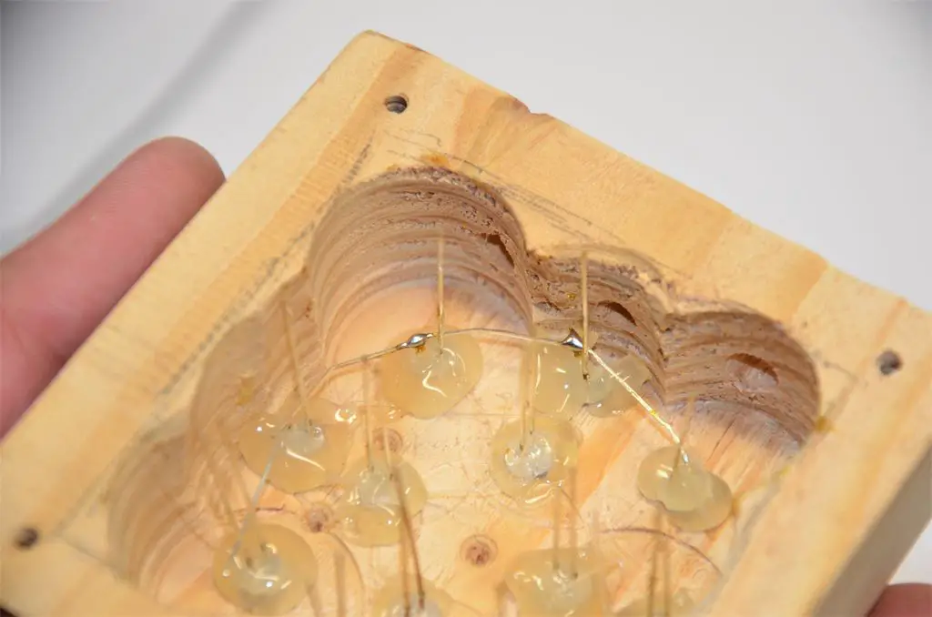
Take a LED and stick it in a hole. Align it so the cathode (shorter lead) is toward the outside. Then put a little hot glue around it!
Repeat this process until all the LEDs are in their holes. Be careful to put the right color in the right hole!
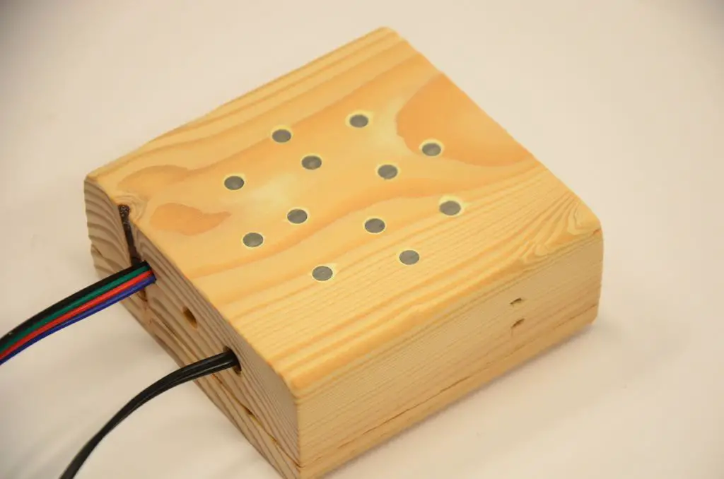
For a more seamless look, sand the LEDs flush with the wood. It works best to sand before the wires are in.
Bend the shorter lead on a LED and touch it to the short leg on the next LED. Solder these two together and continue around the circle. A needle-nose pliers is a big help!
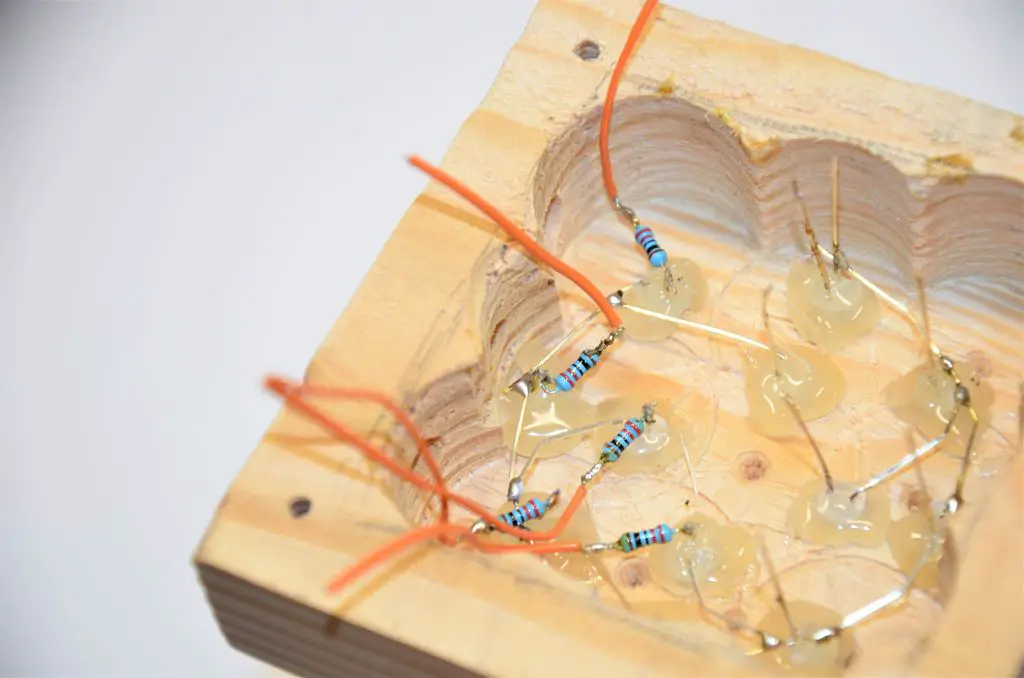
Cut a short length of wire, about two inches long, and strip it! Twist it around a leg of a resistor, it doesn’t matter which end. Use your soldering iron to make the connection permanent! Do this for all your resistors.
Next, grab a resistor-wire pair and carefully solder the free end of it to a LED. Be sure not to let the leads touch any other wires! Do this for each LED, and double-check for shorts.
Finally, solder a short length of wire to the leg that was left when you soldered the grounds.
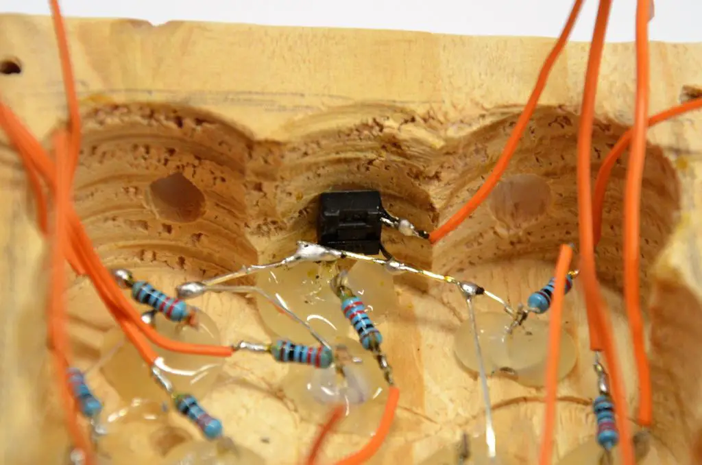
Cut and strip another short length of wire, and solder it to one of the button’s leads. Then clip all the button’s legs off except the one adjacent from your solder joint.
Place the button in the box so you can push it from the outside through the hole. Solder the free lead of the button to the ground connections of the LEDs.
Finally, drizzle a bit of hot glue over the button to keep it in place!
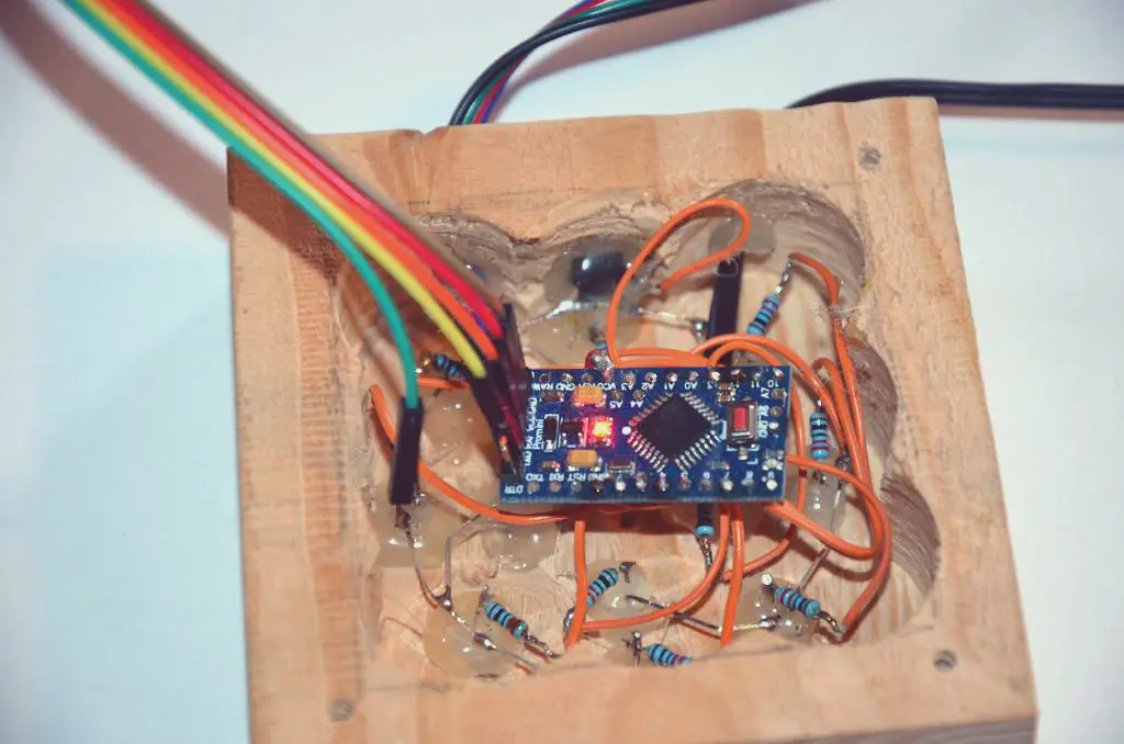
Install And Solder The Arduino
The circuit diagram for the Arduino is shown below.
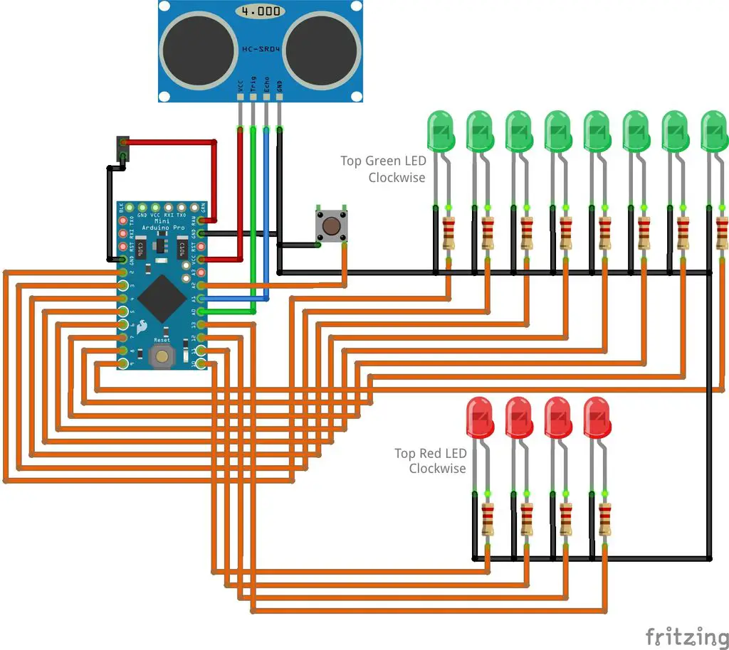
Solder the pin-headers to the programming port of the Arduino. Then push the two wires (from the power supply and the one for the sensor) through their holes and use a bit of hot glue to keep them from falling out.
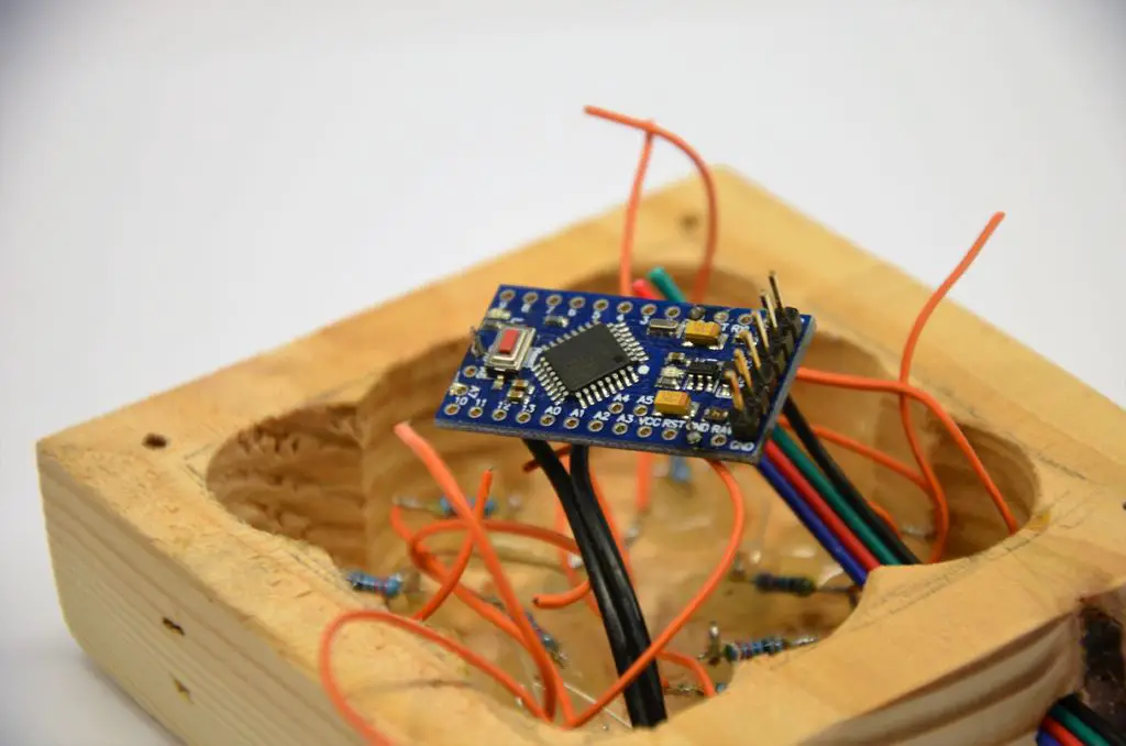
Strip the wires from the LEDs and button and solder them to the Arduino according to the wiring circuit diagram above.
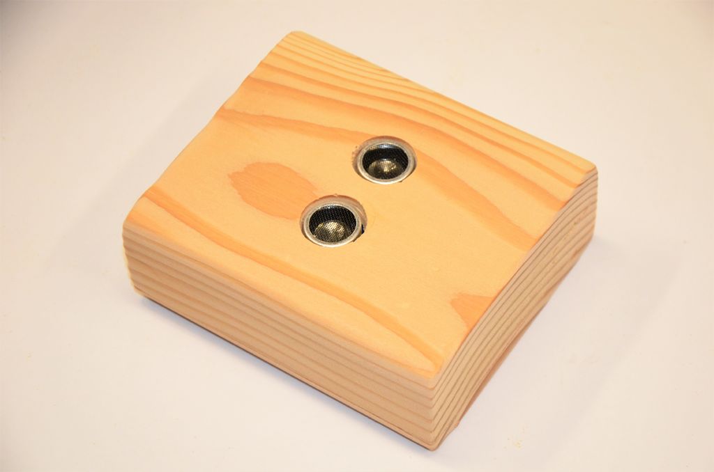
Create The Parking Sensor Enclosure
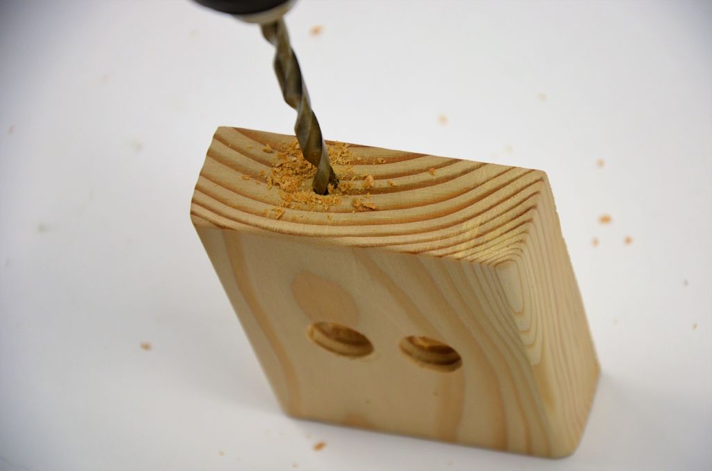
The sensor enclosure is made in the same way as the LED display enclosure. This time, instead of making holes for the LEDs, make holes for the ultrasonic sensors as per the template below.
Connect The Parking Sensor Box To The Display Box
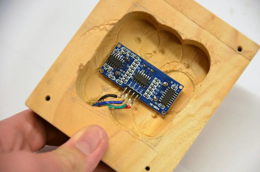
Push the free end of the sensor wire through the hole in the box, then strip it and solder it to the sensor module as in the picture.
- Black goes to GND
- Blue goes to ECHO
- Green goes to TRIG
- Red goes to VCC
Use a bit of hot glue to secure the sensor in the case, then use another dab as stress relief for the cable. Screw the lid on, and you’re done!
Upload The Sketch
The Arduino is programmed using the FTDI Programmer which is connected to the Arduino using the jumpers and pins on the back. Once the programmer is connected to the Arduino, you can upload your sketch, if you haven’t uploaded a sketch before then follow this guide on getting started.
In order to read the sensor, we need the NewPing library. You can download it here, In the Arduino IDE, click on Sketch > Include Library > Add Zip Library… and point it the ‘NewPing.zip’ folder.

Open the sketch in the Arduino IDE and upload it to the Arduino.
#include <NewPing.h> //include the library for the sonar distance sensor
#include <EEPROM.h> //this lets us access the memory
const int G1 = 9;//set the led pins by the color
const int G2 = 8;
const int G3 = 7;
const int G4 = 6;
const int G5 = 5;
const int G6 = 4;
const int G7 = 3;
const int G8 = 2;
const int R1 = 13;
const int R2 = 12;
const int R3 = 11;
const int R4 = 10;
const int trigPin = A0; //set the distance sensor trigger pin to A0
const int echoPin = A1; //the sonar echo pin
const int buttonPin = A2; //the button
NewPing sonar(trigPin, echoPin, 300); //start the distance sensor
const int minDeviation = 5; //the number of inches of movement required to count as moving
const int timeout = 10; //the number of seconds to keep the leds on after movement stops
const int ledDistance = 6; //the distance in inches each led covers
int idealDistance = 5; //this is the perfect distance to the car read from the memory
int rawSonar; //this is the raw data from the distance sensor
int distance; //the distance to the vehicle
int prevDistance = 0; //the previous distance to the vehicle
unsigned long lastMoved = 0; //the millis reading of the last movement
void setup() { //this runs once at startup
pinMode(G1, OUTPUT); //set the leds to output
pinMode(G2, OUTPUT);
pinMode(G3, OUTPUT);
pinMode(G4, OUTPUT);
pinMode(G5, OUTPUT);
pinMode(G6, OUTPUT);
pinMode(G7, OUTPUT);
pinMode(G8, OUTPUT);
pinMode(R1, OUTPUT);
pinMode(R2, OUTPUT);
pinMode(R3, OUTPUT);
pinMode(R4, OUTPUT);
pinMode(buttonPin, INPUT_PULLUP); //set button as input with internal pull-up resitors
if (EEPROM.read(0) != 255) { //read the memory, it will read 255 if it's never been written to
idealDistance = EEPROM.read(0); //set the idealDistance from the memory
}
Serial.begin(9600);
}
void loop() { //this runs over and over again
delay(100); //wait 100 ms to get accurate readings
rawSonar = sonar.ping_median(5); //get 5 readings and average them
if (rawSonar != 0) { //the distance sensor sends a 0 when nothing is in range
distance = rawSonar / US_ROUNDTRIP_IN; //convert the raw data the inches
distance -= idealDistance; //subtract the ideal distance from the reading, giving us the distance to go
}
else {//if the car isn't in range
setLEDs(0, 0, 0, 0, 0, 0, 0, 0, 0, 0, 0, 0); //turn the LEDs off
}
if (abs(distance - prevDistance) >= minDeviation) { //if the car has moved since last read
lastMoved = 0; //reset the sleep timer
prevDistance = distance; //reset the distance last read
if (distance < ledDistance * 9 && distance >= ledDistance * 8) { //if it's in the 1st led's range
setLEDs(1, 0, 0, 0, 0, 0, 0, 0, 0, 0, 0, 0);
}
else if (distance < ledDistance * 8 && distance >= ledDistance * 7) { //if in range of the 2nd led
setLEDs(1, 1, 0, 0, 0, 0, 0, 0, 0, 0, 0, 0);
}
else if (distance < ledDistance * 7 && distance >= ledDistance * 6) { //if in range of the 3rd led
setLEDs(1, 1, 1, 0, 0, 0, 0, 0, 0, 0, 0, 0);
}
else if (distance < ledDistance * 6 && distance >= ledDistance * 5) { //if in range of the 4th led
setLEDs(1, 1, 1, 1, 0, 0, 0, 0, 0, 0, 0, 0);
}
else if (distance < ledDistance * 5 && distance >= ledDistance * 4) { //if in the 5th led
setLEDs(1, 1, 1, 1, 1, 0, 0, 0, 0, 0, 0, 0);
}
else if (distance < ledDistance * 4 && distance >= ledDistance * 3) { //if in range of the 6th led
setLEDs(1, 1, 1, 1, 1, 1, 0, 0, 0, 0, 0, 0);
}
else if (distance < ledDistance * 3 && distance >= ledDistance * 2) { //if in range of the 7th led
setLEDs(1, 1, 1, 1, 1, 1, 1, 0, 0, 0, 0, 0);
}
else if (distance < ledDistance * 2 && distance >= ledDistance) { //if in range of the 8th led
setLEDs(1, 1, 1, 1, 1, 1, 1, 1, 0, 0, 0, 0);
}
else if (distance <= idealDistance) { //if in the stop position
setLEDs(0, 0, 0, 0, 0, 0, 0, 0, 1, 1, 1, 1);
}
}
else { //if the car isn't moving
if (lastMoved == 0) { //if the timer hasn't been started
lastMoved = millis(); //set the timer
}
if (lastMoved != 0 && millis() - lastMoved >= timeout * 1000) { //if the timer is set and past the timeout
setLEDs(0, 0, 0, 0, 0, 0, 0, 0, 0, 0, 0, 0); //turn off the leds
lastMoved = 0; //turn off the timer
}
}
//this checks the button
if (digitalRead(buttonPin) == LOW) { //if the button is being pressed
rawSonar = sonar.ping_median(30); //get 30 readings and average them
if (rawSonar != 0) { //the distance sensor sends a 0 when nothing is in range
distance = rawSonar / US_ROUNDTRIP_IN; //convert the raw data the inches
EEPROM.write(0, distance); //write the distance to the memory
idealDistance = distance; //set the idealDistance
flashGreen(); //show success
}
else { //if out of range
flashRed(); //show error
}
}
}
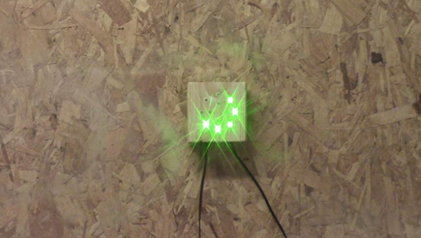
void flashGreen() { //this flashes the green LEDs to show success
setLEDs(0, 0, 0, 0, 0, 0, 0, 0, 0, 0, 0, 0); //clear the leds
setLEDs(1, 1, 1, 1, 1, 1, 1, 1, 0, 0, 0, 0); //turn the green leds on
delay(500); //wait
setLEDs(0, 0, 0, 0, 0, 0, 0, 0, 0, 0, 0, 0); //turn all the leds off
delay(500); //wait
setLEDs(1, 1, 1, 1, 1, 1, 1, 1, 0, 0, 0, 0); //turn the green leds on
delay(500); //wait
setLEDs(0, 0, 0, 0, 0, 0, 0, 0, 0, 0, 0, 0); //turn the green leds off
}
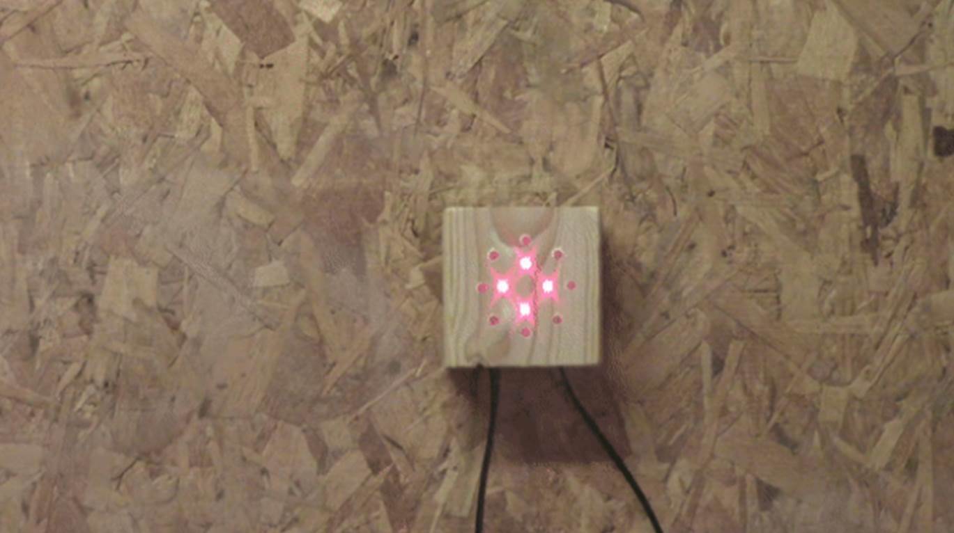
void flashRed() { //this flashes the red LEDs to show success
setLEDs(0, 0, 0, 0, 0, 0, 0, 0, 0, 0, 0, 0); //clear the leds
setLEDs(0, 0, 0, 0, 0, 0, 0, 0, 1, 1, 1, 1); //turn the red leds on
delay(500); //wait
setLEDs(0, 0, 0, 0, 0, 0, 0, 0, 0, 0, 0, 0); //turn all the leds off
delay(500); //wait
setLEDs(0, 0, 0, 0, 0, 0, 0, 0, 1, 1, 1, 1); //turn the red leds on
delay(500); //wait
setLEDs(0, 0, 0, 0, 0, 0, 0, 0, 0, 0, 0, 0); //turn all the leds off
}
//this function simply sets the leds to the parameters you send it
void setLEDs(int led1, int led2, int led3, int led4, int led5, int led6, int led7, int led8, int led9, int led10, int led11, int led12) {
digitalWrite(G1, led1);
digitalWrite(G2, led2);
digitalWrite(G3, led3);
digitalWrite(G4, led4);
digitalWrite(G5, led5);
digitalWrite(G6, led6);
digitalWrite(G7, led7);
digitalWrite(G8, led8);
digitalWrite(R1, led9);
digitalWrite(R2, led10);
digitalWrite(R3, led11);
digitalWrite(R4, led12);
}
Download The Sketch – ParkingSystem
Screw on the lid, and your parking assistant is ready to be installed.
Using the Arduino Parking Assistant
Mount The Parking Sensor And Display
Mount the sensor on your garage wall where it can sense a flat surface on your car’s bumper, not the grill! Mount the control box higher up where it’s visible from inside the vehicle.
Calibrating The Parking Sensor
Park your car in the best position, and use a long object like a pencil to push the button on the bottom. This will calibrate it. Be sure you’re not standing in front of the sensor!
When you drive into your garage, slowly approach the parking assistant; the green LEDs show your distance to the ideal parking spot, red shows you when to stop to park in the perfect position!
Have you built your own Arduino based parking assistant? Let us know in the comments section below.
This post is based upon Arduino Parking Assistant by addictedToArduino and is used and modified under the Creative Commons license CC-BY-NC-SA.