In this project, we will connect an LCD screen to an Arduino and use it to display some basic text. This covers both the physical connections and the programming required to get an LCD to work. If this is your first project then we recommend that you familiarise yourself with programming an Arduino first.
This project consists of two parts, one which prints Hello World, The DIY Life and a second which prints The DIY Life and then prints a seconds since start-up counter on the second line.
The screens we are covering in this project have 16 pin parallel interfaces, meaning that the Arduino has to send data on multiple pins at the same time in order to change the screen text. Fortunately, the Arduino has a built in library for LCD screens which are compatible with the Hitachi HD44780 driver so we can make use of the built in function library and do not have to manually code functions to control the screen.
To understand the basic on how the screen is operated, there are three pins which control the registers (RS, RW and E), then 8 data transfer pins (D0-D7) and finally a set of pins to provide power, control the contrast and turn the backlight on and off. For displaying general text you only need to make use of 4 of the data transfer pins as the screen will be running in 4 bit mode.
What You’ll Need To Connect An LCD Screen To An Arduino
- Arduino (Uno Used in this Example) – Buy Here
- LCD Screen (Compatible with Hitachi HD44780 Driver) – Buy Here
- Thin Gauge Insulated Wire
- 10K Potentiometer (To change contrast) – Buy Here
- 220Ω LED Backlight Resistor – Buy Here
- Soldering Iron and Solder Wire – Buy Here
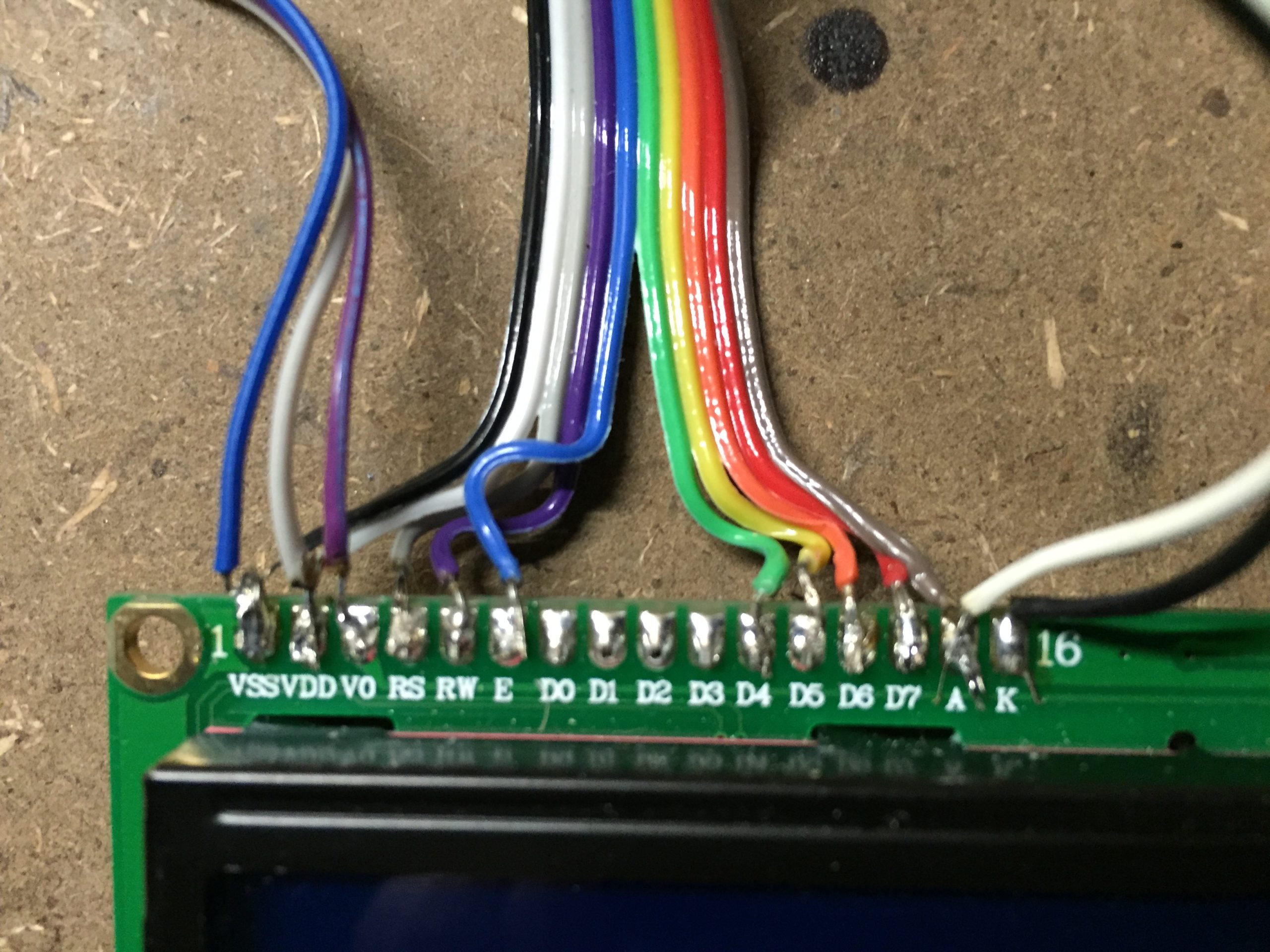
Firstly you need to connect the screen up as shown in the diagram below. This can be done in one of two ways. You can solder a wire ribbon onto the screen and then pins on to the ends of the wires which then plug directly into the Arduino or you can solder a pin header onto the screen and plug it into a breadboard which you can then connect to the Arduino using jumpers.
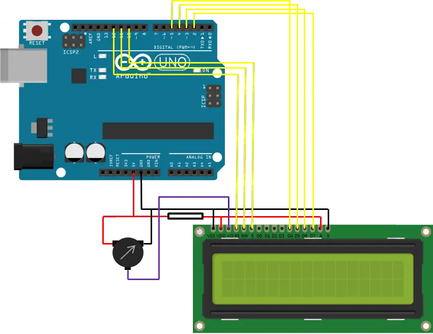
The 10K pot is used to adjust the contrast of the screen. The 220Ω resistor is connected along the positive supply for the back light in order to limit the current.
The pin connections to the LCD screen are as follows: Pin 10, 11 and 12 are used to control the registers and are connected to the E, RW and RS pins respectively. Pins 2,3,4 and 5 are the data transfer pins and are connected to d7, d6, d5 and d4 respectively. Be careful when connecting the pins as the numerical sequence on the Arduino pins is the opposite to the screen pins.
Upload the Code to Control the LCD Screen
Displaying Static Text
Now you can begin the coding. For the first example, we will only be using the setup loop as we just need the screen to display “Hello World” and “The DIY Life” on the screen without any further changes.
// Michael Klements
// LED Screen Example
// 25 August 2016
// www.the-diy-life.com

#include <LiquidCrystal.h>

LiquidCrystal lcd(12, 11, 10, 5, 4, 3, 2);

void setup()
{
  lcd.begin(16,2);              // Defines the number of characters and rows
  lcd.clear();                  // Clear the screen
  lcd.setCursor(0,0);           // Set the cursor to first character, first row
  lcd.print("Hello World");     // Display this text
  lcd.setCursor(0,1);           // set cursor to column 0, row 1
  lcd.print("The DIY Life");
}

void loop()
{

}
Here is a link to the Hello World code.
We begin by importing the Liquid Crystal library. This enables us to use short functions to control the screen instead of having to manually code each letter or cursor movement.
Next we create an object called lcd as an instance of the Liquid Crystal library. Here we also need to assign the pins which we have setup above.
Now we move on to the setup code method. We first tell the lcd object how many columns and rows or characters our screen has. In this case the screen size is 16 x 2. We then clear the screen to ensure that it is blank, set the cursor to the first row and first character, then begin sending the text “Hello World” to the screen. We then tell the cursor to move to the second row of characters and print “The DIY Life”.
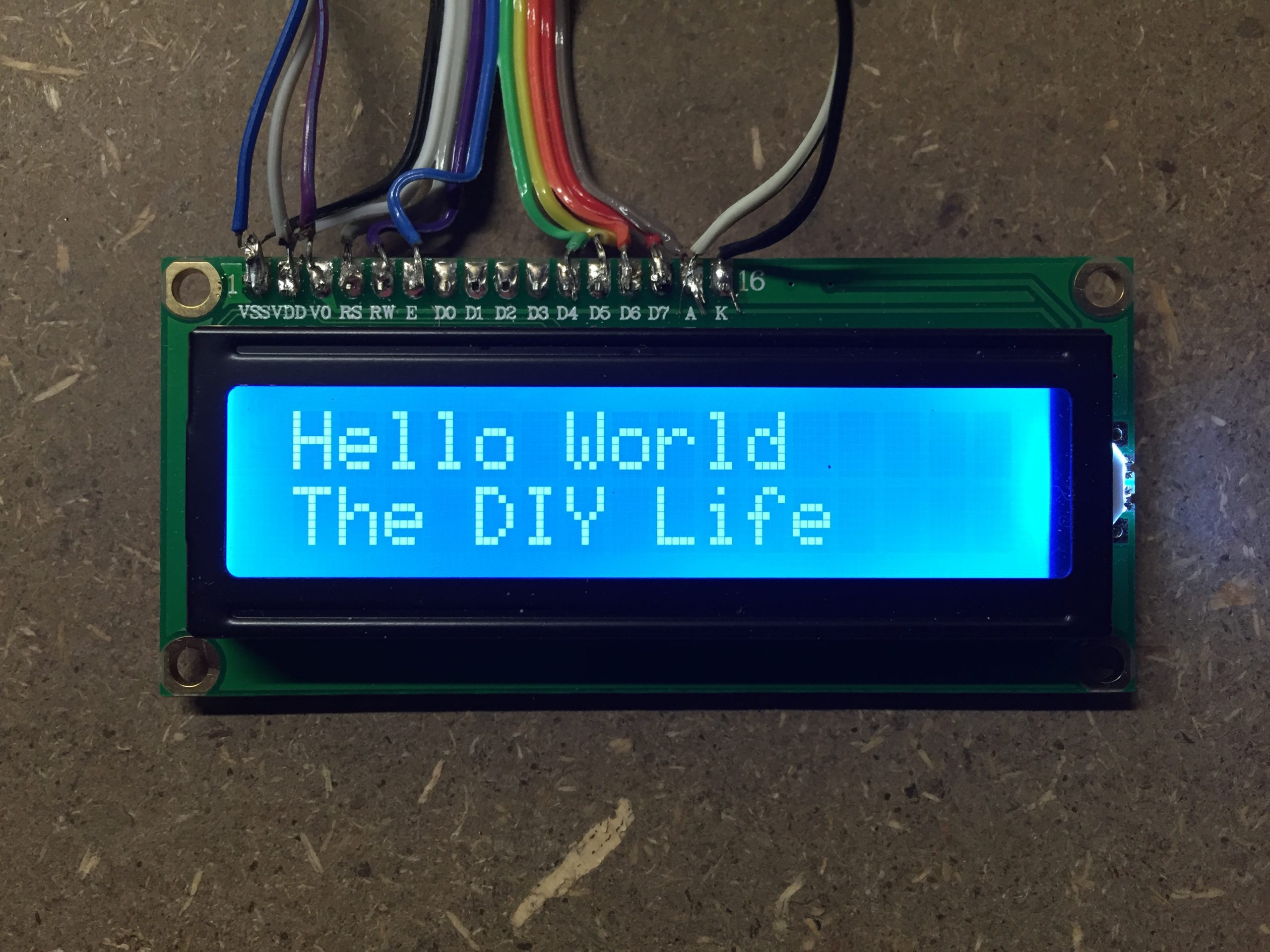
If you have connected everything correctly then the screen should now display Hello World on the first line and The DIY Life on the second line. You may need to play around with the contrast adjustment on the 10K pot to make the text visible, this adjustment is shown in the video below:
Displaying A Counter
Now we can move onto using the loop function to constantly change information on the screen. First we remove “Hello World” and move “The DIY Life” to the first row, this is all done in the setup function.
// Michael Klements
// LED Screen Example
// 25 August 2016
// www.the-diy-life.com

#include <LiquidCrystal.h>

LiquidCrystal lcd(12, 11, 10, 5, 4, 3, 2);

void setup()
{
  lcd.begin(16,2);              // Defines the number of characters and rows
  lcd.clear();                  // Clear the screen
  lcd.setCursor(0,0);           // Set the cursor to first character, first row
  lcd.print("The DIY Life");     // Display this text
}

void loop()
{
  for (int i=0;i<=100;i++)
  {
    lcd.setCursor(0,1);           // set cursor to column 0, row 1
    lcd.print(i);                 //Display the number i
    delay(1000);
  }
}
Here is a link to the Timer code.
We now create a loop in the loop function which counts from 1 to 100 seconds and displays this in the second row of the screen.
When you run this code you should see The DIY Life in the first row and a counter which updates every second in the second row and runs until 100 seconds. The counter in operation is shown in the video below:
You have now covered the basics on connecting an LCD screen to the Arduino and using the built in control functions to change the text displayed on the screen.
Would you like to learn more about this project? Are you interested in projects similar to this one? Then Practical Arduino Projects is the book for you, available now on Amazon as an eBook or in Print form.
Hi!
I am successfully using an Arduino Pro Micro with that display you’re using.
My display part stays dark as if my backlight led are not working.
I CAN see the letters, though.
Is something wrong with my Arduino Pro Micro?
I have the layout from here:
https://www.instructables.com/Arduino-RGB-Color-Picker-Pick-Colors-From-Real-Lif/
best regards,
Denis
Hi Denis,
The backlight isn’t driven by the pro-micro, so its not likely that the Arduino is causing the trouble. The backlight just comes on when voltage is applied to the backlight pins on the LCD.
You’ve more likely got a connection problem on the end two pins (A and K) which supply voltage to the backlight, or less likely, the backlight is blown.
Thank you Michael,
I will check that and get back to you when further questions come up 😉
best regards,
Denis