This guide takes you through all of the steps required to make your own Xduino board for your own custom projects. I had a project which required an Arduino board to control four servos. I considered using the Seeeduino Lotus because it had a number of Grove ports and I thought it might be convenient for my servo project. Unfortunately, there were a two major problems with using the Seeeduino Lotus:
- The servos draw too much current from the board’s power supply which caused the board to reboot unexpectedly.
- The cabling to the servos was a mess as the three pins on each servo had to be wired to different places on the board.
I therefore decided to build my own Arduino board for the project. I decided to call it Servoduino since it would be primarily used to control servos. The board would have the following features:
- Arduino compatible and easy to program
- Direct plug in for 8 servos
- A strong enough power supply to drive the 8 connected servos
Initially, it seemed difficult and expensive to build my own Arduino board, but then I found out about Seed Fusion. They offer PCB and PCBA manufacturing and fabrication which is affordable, quick and of good quality.
Steps To Building Your Xduino
- List Features Required By Your Xduino
- Select Components
- Draw Up A Schematic
- Design The Component Layout
- Manufacture The PCB and do PCBA
- Upload The Bootloader
- Upload The Servo Control Code
List the Features Required by your Xduino
To start with, you need to know what you’d like your Xduino to be able to do. You need to list the interfaces, number and type of inputs and outputs etc. Here is a list of the requirements for my Servoduino.
- Arduino Compatible & Easy To Program
- 8 Servo Connectors – 3 Pins Each
- A Power Supply Sufficient For 8 Servos
- 9-12V Input Power
- Micro USB Programming
Selecting Components
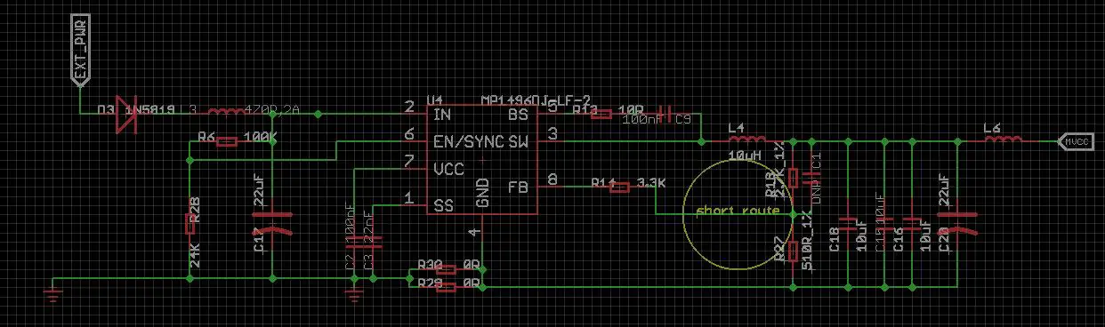
Once you’ve decided on what you’d like your Xduino board to be able to do, you’ll need to choose your major components in order to enable this. The most important part of any Xrduino board is the MCU. For this, I have chosen to use the ATmega328P chip. For the USB to UART part, we commonly use the ATmega16u2 chip. Finally, for the power supply, we will need a strong DC-DC supply chip. I’ve chosen to use the MP1496DJ-LF-2 chip which is able to produce 2A current with a 4.5V-16V input voltage.
Draw Up A Schematic
For the schematic design, I’ve chosen to use Autodesk EAGLE. There are a large number of open source hardware projects which have been designed using EAGLE, it’s easy to use and the free version has enough functionality to suite most people’s requirements. You can download a free version of Autodesk EAGLE here.
If you have not used EAGLE before, then here is a nice guide to get started.
Thanks to the open source EAGLE platform, I don’t have to design the board from scratch, I can choose a similar design and modify it to suite my requirements. I decided to design my Servoduino based on Seeeduino v4.2, which also has an ATmega328P and ATmega16u2 chip and is more stable than the Arduino UNO R3. I downloaded the schematic for the Seeeduino v4.2 from Seeed’s Wiki.
I opened the schematic and found that I didn’t have to change too many things.
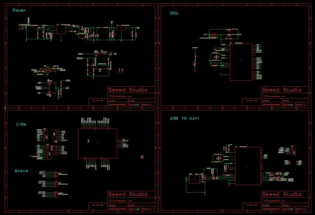
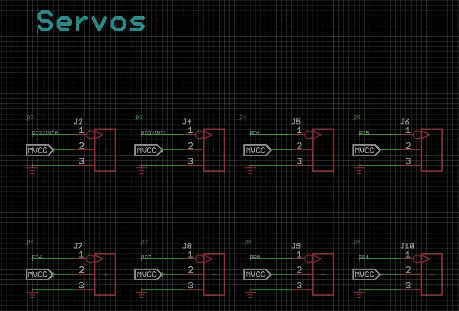
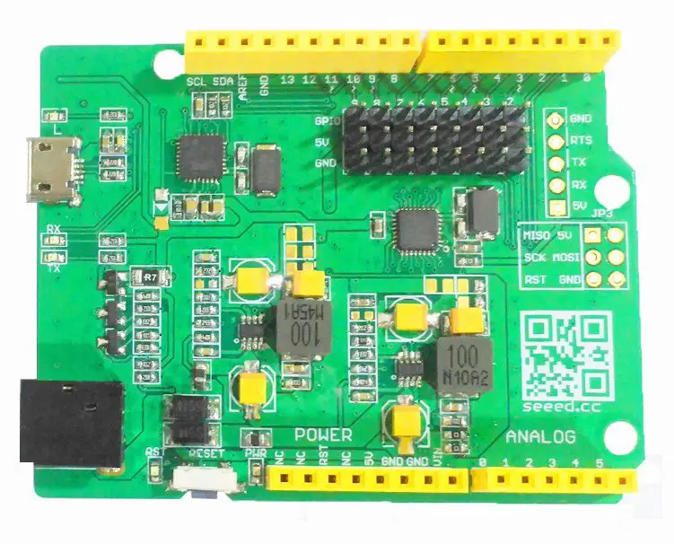
Firstly, I needed to add the 8 3-pin headers for servo plugs. The 3 pins of the header are the VCC (5V), GND and SIG (PWM signal). The VCC pins will be connected directly to the second power chip and the SIG pins will be connected to D2-D9 of ATmega328P.
Secondly, I added another MP1496DJ-LF-2 DC-to-DC chip to power the servos. The MVCC net is only for the servos and would not affect the system power supply.
I also deleted the 3 Grove ports on Seeeduino because I would not need them.
I used as many parts as possible from the Seeed Open Parts Library throughout the design, this would enable me to make used of their PCBA service.
Design The Component Layout
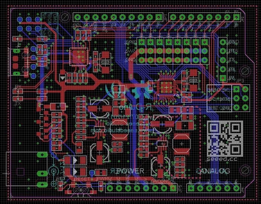
Now that I have completed the schematic design, I could design the PCB layout. In this step, you could either make use of the CAD software to design your layout and base it upon an existing Arduino board or you could make use of a PCB layout services. I sent my schematic through to Seeed and they did my PCB layout for me.
Manufacture The PCB and do PCBA
Once your layout is complete, you’ll need to generate your Gerber files for manufacturing the PCB. You’ll then need to find a manufacturer who will be able to produce your board.
I chose to use the Seeed Fusion PCB service, they charged me $4.90 for 10 boards (10cm x 10cm in size) and provided me with great technical support and documentation.
Once you have received your completed boards, you’ll need to buy components and solder the boards. Here, again, I decided to use the Seeed Fusion PCBA service to assemble my boards. They charge a single fee of $25 to set up. Because I used parts from the Seeed Open Parts Library, the delivery time was only 7-15 days.
All you need to order your boards is to go to their website, uploaded the Gerber files and your bill of materials and then make the payment to them, it is that easy.
Upload The Bootloader
Now that your boards are complete, you’ll need to program them. The first step is to upload the bootloader to Servoduino using a AVR ISP (In-System Programmer). If you don’t have a AVR ISP, you can use any Arduino/Seeeduino board as an AVR ISP to upload bootloader to your Xduino by following these steps:
- Download the code
- Upload the code to your Arduino/Seeeduino board you are using as an AVR ISP
- Connect the two boards as in the list below:
- Seeduino/Arduino D11 – Servoduino/Xduino D11
- Seeduino/Arduino D12 – Servoduino/Xduino D12
- Seeduino/Arduino D13 – Servoduino/Xduino D13
- Seeduino/Arduino D10 – Servoduino/Xduino RST
- Seeduino/Arduino 5V – Servoduino/Xduino 5V
- Seeduino/Arduino GND – Servoduino/Xduino GND
- Open the Serial Monitor in Arudino IDE, type “U”, and then ”G”. If it doesn’t raise any errors, then the upload is successful.
Upload The Servo Control Code
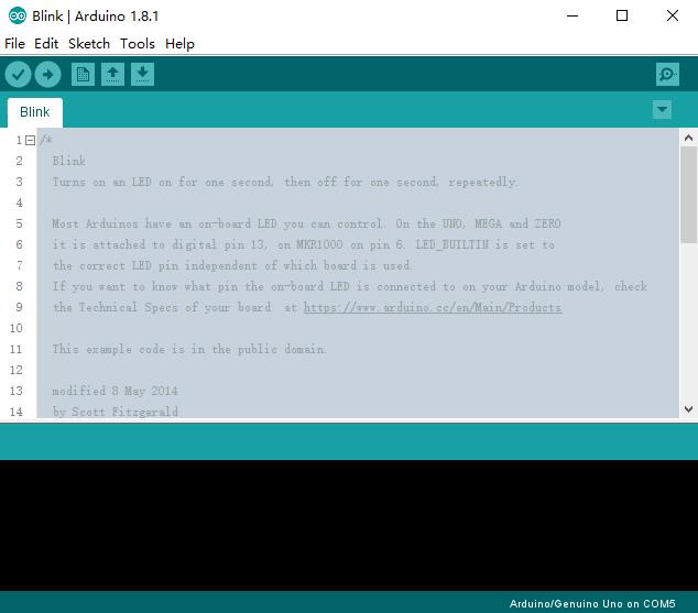
Now that the bootloader has been uploaded, you can try and upload your first program using the Arduino IDE. Select “Arduino UNO” in the Tools>Boards menu and select the correct COM port before uploading. To start with, try and upload the Blink example code built into the Arduino IDE.
Once you’ve connected power to the board and attempted to upload your test code, you may run into a problem as listed below:
- Can’t find the COM Port after connecting the board
- Upload fails
- The board gets hot
These cases are almost always caused by bad soldering, check the board carefully if any of these happen. If you run the blink example and it works well, you can move onto uploading your servo code.
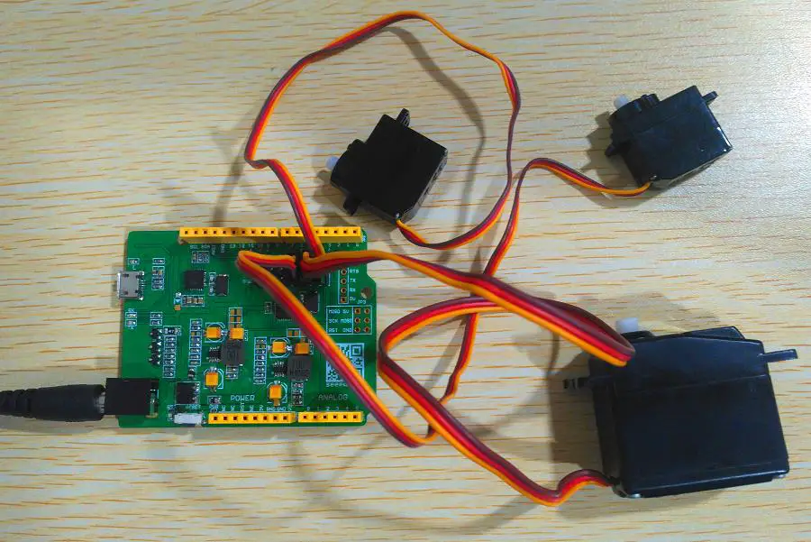
Four servos were attached to the Servoduino board and the following code was uploaded.
/* Sweep
 by BARRAGAN <http://barraganstudio.com>
 This example code is in the public domain.

 modified 8 Nov 2013
 by Scott Fitzgerald
 http://www.arduino.cc/en/Tutorial/Sweep
*/

#include <Servo.h>

Servo myservo;  // create servo object to control a servo
// twelve servo objects can be created on most boards

int pos = 0;    // variable to store the servo position

void setup() {
  myservo.attach(9);  // attaches the servo on pin 9 to the servo object
}

void loop() {
  for (pos = 0; pos <= 180; pos += 1) { // goes from 0 degrees to 180 degrees
    // in steps of 1 degree
    myservo.write(pos);              // tell servo to go to position in variable 'pos'
    delay(15);                       // waits 15ms for the servo to reach the position
  }
  for (pos = 180; pos >= 0; pos -= 1) { // goes from 180 degrees to 0 degrees
    myservo.write(pos);              // tell servo to go to position in variable 'pos'
    delay(15);                       // waits 15ms for the servo to reach the position
  }
}
When the upload was complete, the four servos moved as per the code.
I can now use my Servoduino to complete my project, please visit my Instructables page to see me projects. My project is currently still made with Seeeduino Lotus but I will publish a new project based on my Servoduino soon.