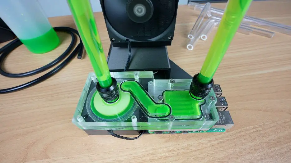
Today’s project is a little ridiculous, but in the best way possible. I’ve built a custom waterblock for the Raspberry Pi 5, and I’ve gone all out. This block features a milled aluminium cold plate, an integrated clear acrylic distribution plate, a built-in pump, and hardline tubing leading to an 80mm radiator and fan.
It’s complete overkill… and that’s exactly the point.
Here’s my video of the build, read on for the write-up;
Parts Used For This Project
- Raspberry Pi 5 – Buy Here
- Low Profile Pump – Buy Here
- 80mm Radiator – Buy Here
- 80mm Slim Cooling Fan – Buy Here
- 12mm Hardline Tubing – Buy Here
- 12mm Compression Fittings – Buy Here
- Adjustable Power Supply – Buy Here
Tools & Equipment Used:
- Makera Cavera Air – Buy Here
- Carvera Air Bits – Buy Here
- Bambulab P1S Combo – Buy Here
- 8mm Silicon Bending Insert – Buy Here
- Milwaukee M18 Heat Gun – Buy Here
Some of the above parts are affiliate links. By purchasing products through the above links, you’ll be supporting this channel, at no additional cost to you.
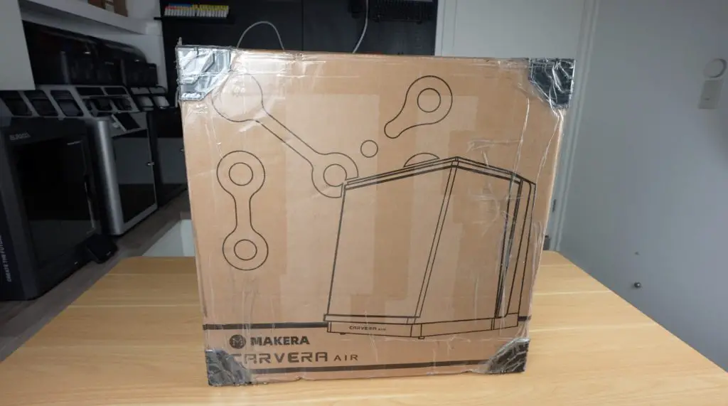
Making With the Carvera Air Desktop CNC
The entire waterblock was machined using the new Carvera Air, a desktop CNC machine that’s genuinely expanded what I can do in my workshop. While Makera did send me this unit for the video, I was already a backer on Kickstarter last year and have been using mine to fabricate parts for my other projects. You might have even spotted it in the background of a few recent videos.
For this build, I pushed it to its limits by milling aluminium and acrylic with precision.
I’ve built a few water-cooled Raspberry Pi projects before, but they usually end up bulky. This time, I wanted to combine water cooling with a compact custom distribution plate, aiming to make something truly unique and much smaller.
The Waterblock & Cooling Loop Design
As always, I started designing the components in Fusion360.

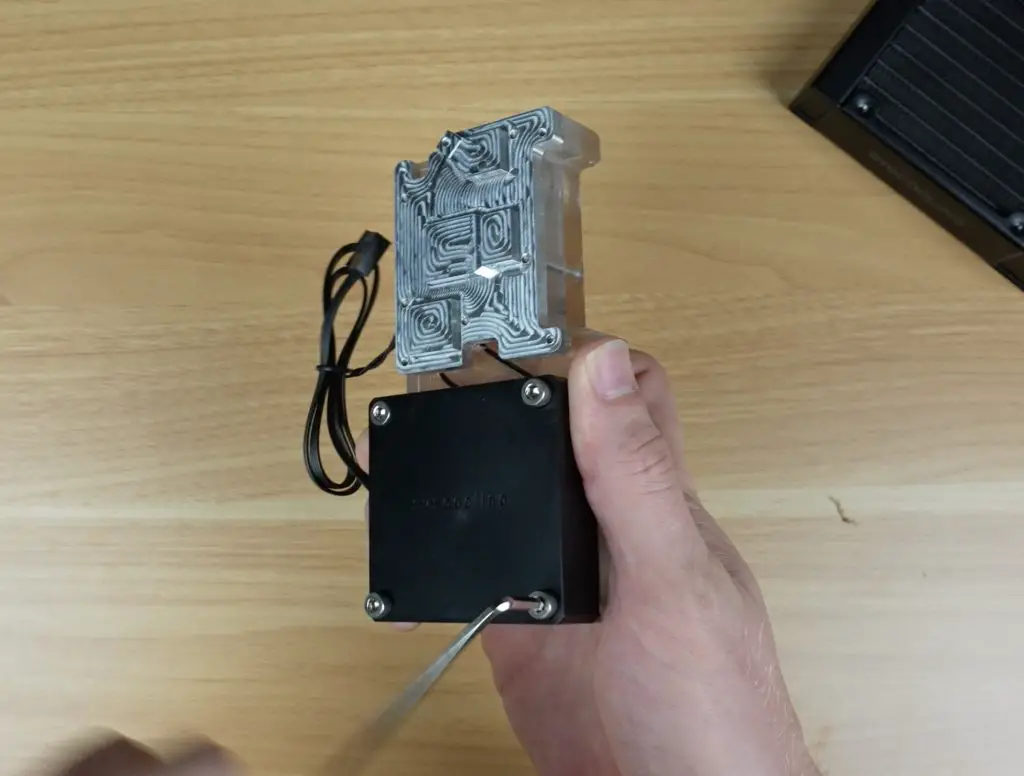
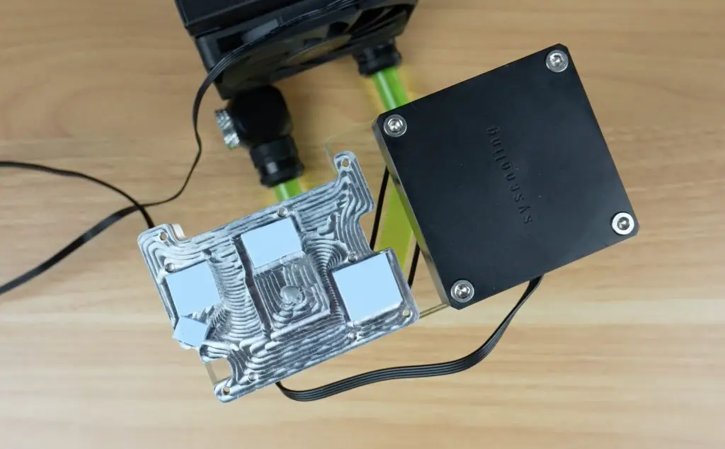
At the heart of the system is a milled aluminium block that makes direct contact with the Pi’s heat-generating components. The CPU is the main target, but I’ve also sized thermal pads for the RAM, USB and Ethernet controllers, and the power circuitry—taking full advantage of the additional cooling capacity.
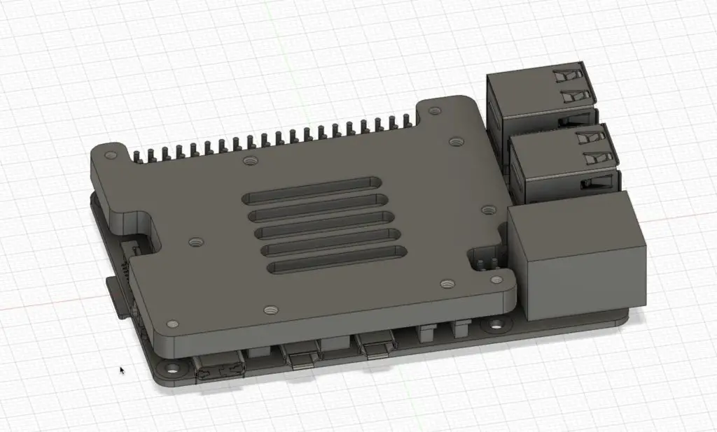
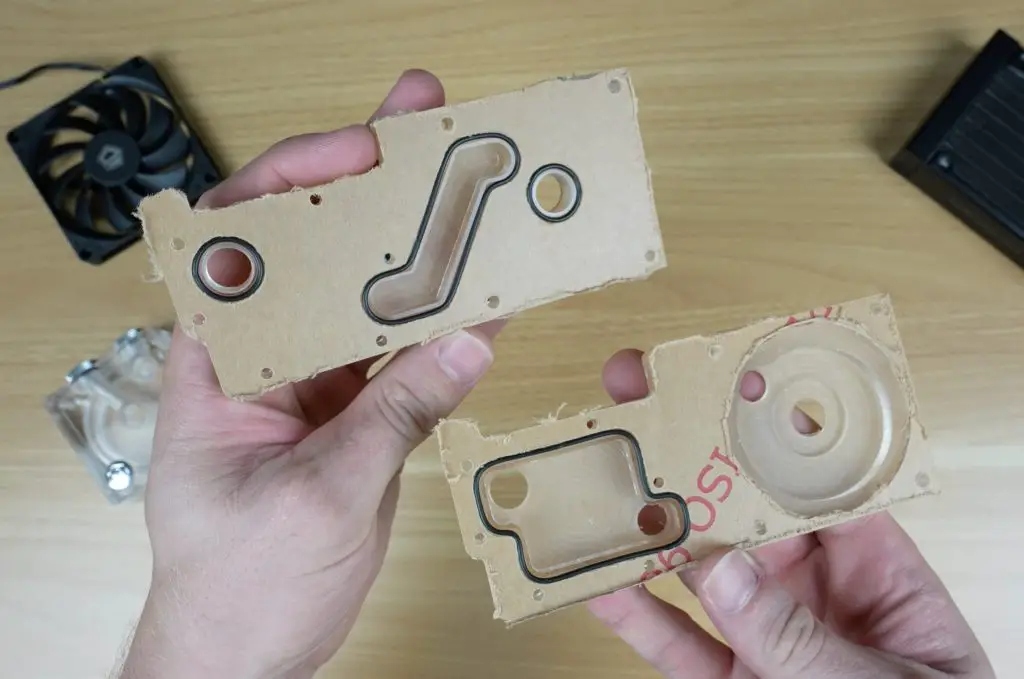
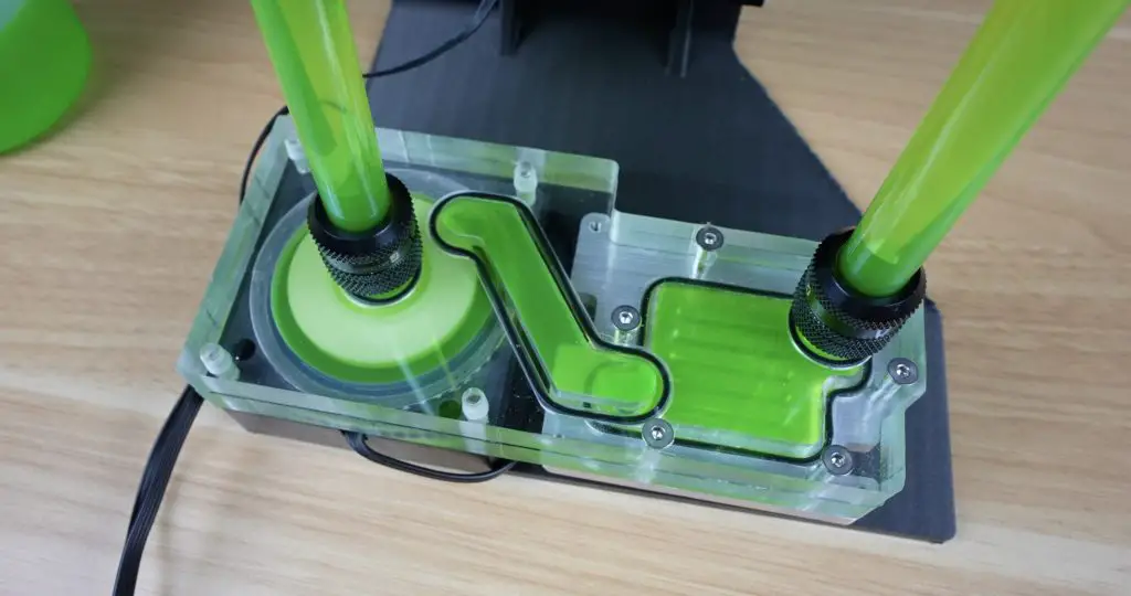
To complete the waterblock, stacked on top is a two-layer acrylic distribution plate. This plate not only channels coolant over the block but also houses the pump itself.
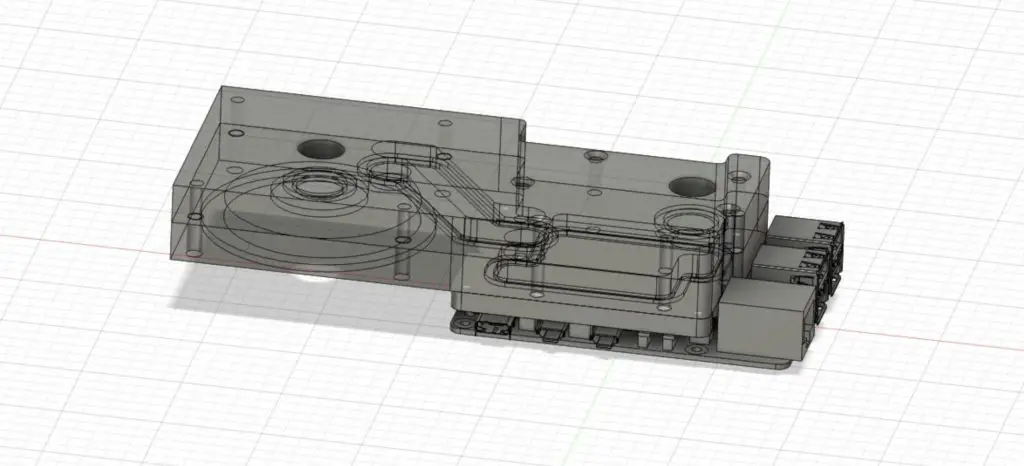
I used a low-profile pump with an acrylic top and reverse-engineered the cutout to fit it seamlessly. The pump mounts directly into the plate with M4 screws and some M3 countersunk screws secure the acrylic layers to the aluminium base. I also custom made gaskets to ensure a good seal between the layers.
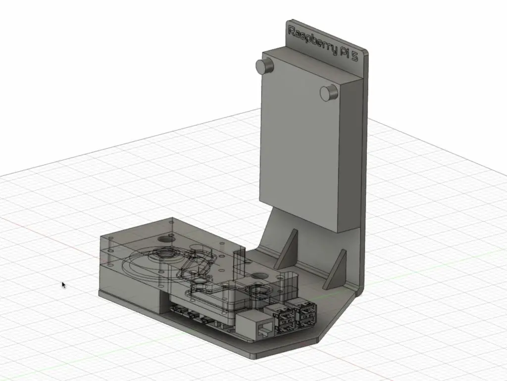
To keep everything clean and compact, I designed a small 3D-printed stand for the radiator next to the Pi. I opted for hardline tubing for aesthetics, though I didn’t bother trying to model the bends in CAD, that was a challenge for later.
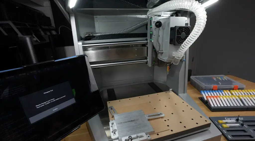
Machining the Components on the Carvera Air
I began making the waterblock with the aluminium cold plate, which would take the longest to mill. Setting up the toolpaths in Fusion360 was a process in itself. A note for those using the free version, it doesn’t allow exporting multiple tool operations into a single CNC file. To get around this, you can either combine the GCode manually or used Makera’s new CAM software.
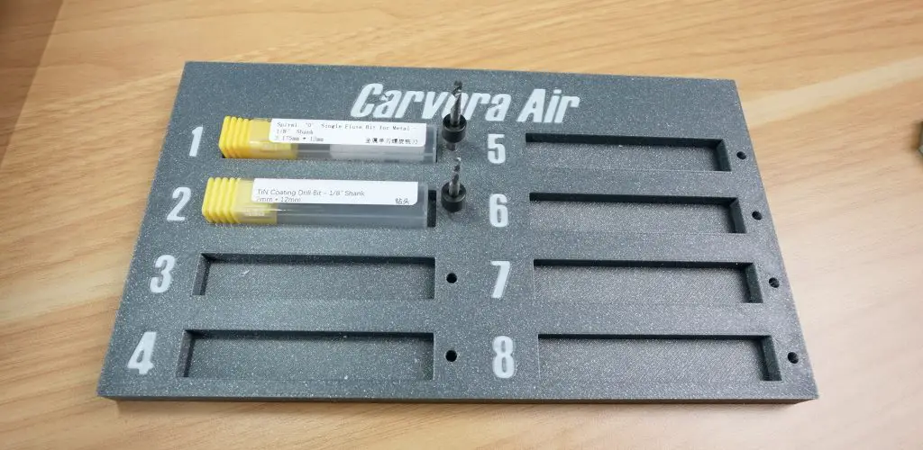
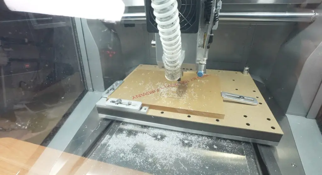
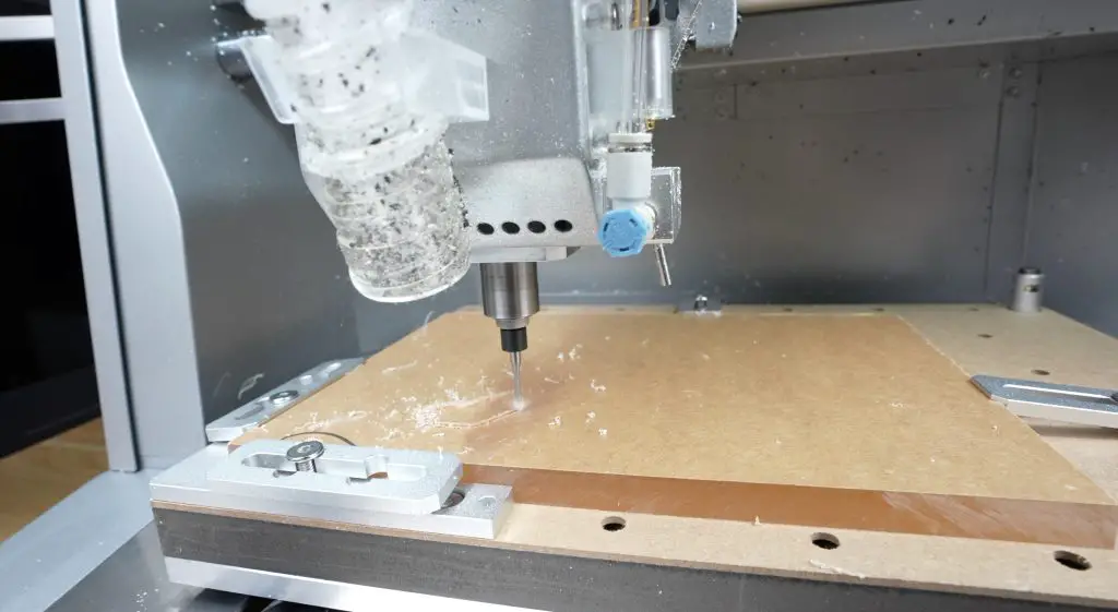
The 10mm aluminium stock was clamped onto the Carvera Air’s bed. While this machine doesn’t have an automatic tool changer, there are some excellent 3D printable tool holders that help keep everything organized.
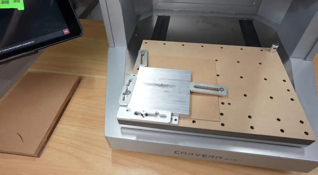
Before cutting, the Carvera Air performed auto-leveling with its probe.
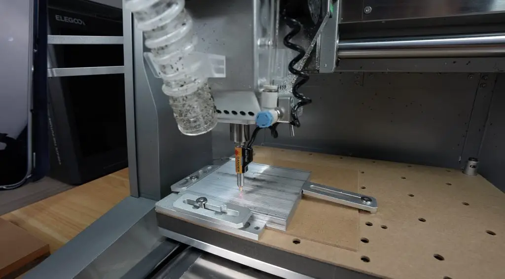
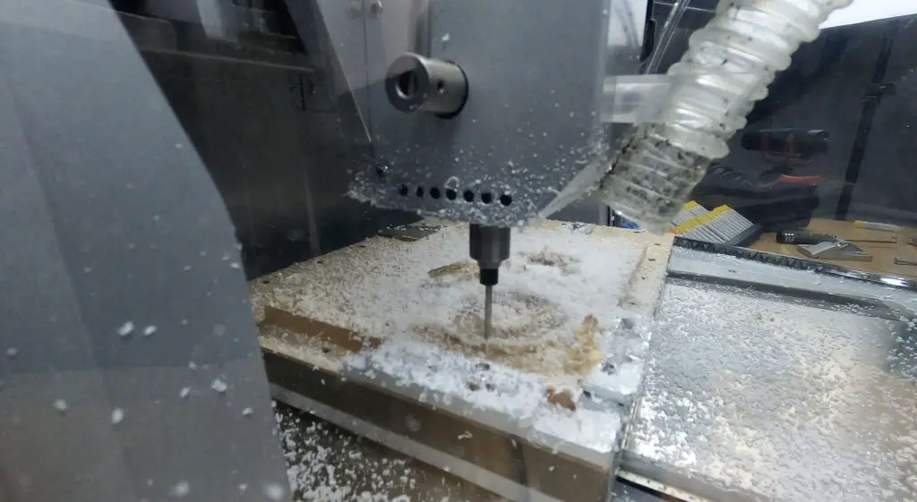
The machining process involved several steps:
- Facing the stock with a 1/8″ flat endmill to the final thickness.
- Drilling holes for the acrylic plate screws and Pi mounts.
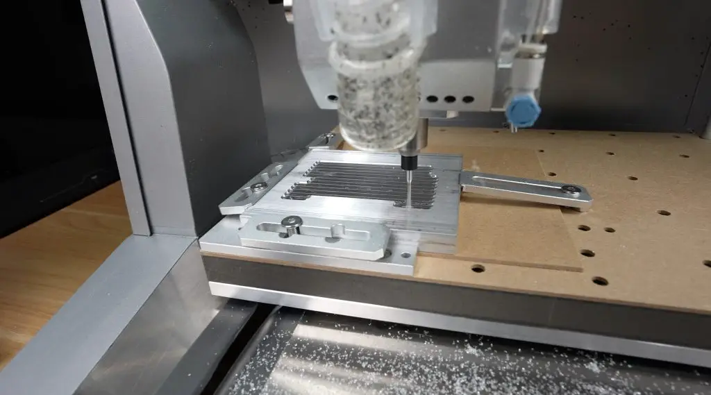
- Surfacing the heat pads and cleaning surrounding areas.
- Contouring the outer shape, with tabs to keep it secured.
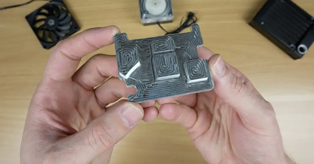
- Flipping the plate to mill the internal cooling channels.
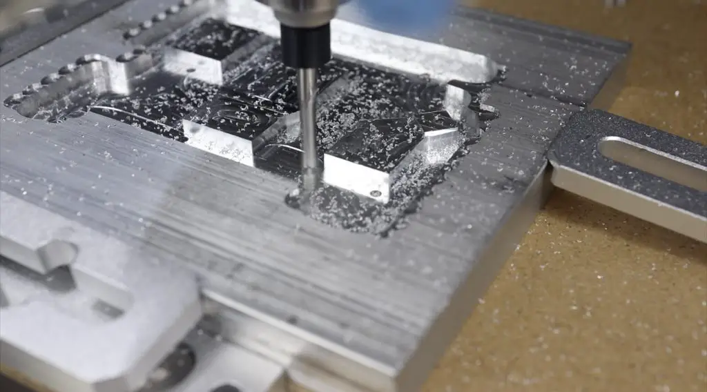
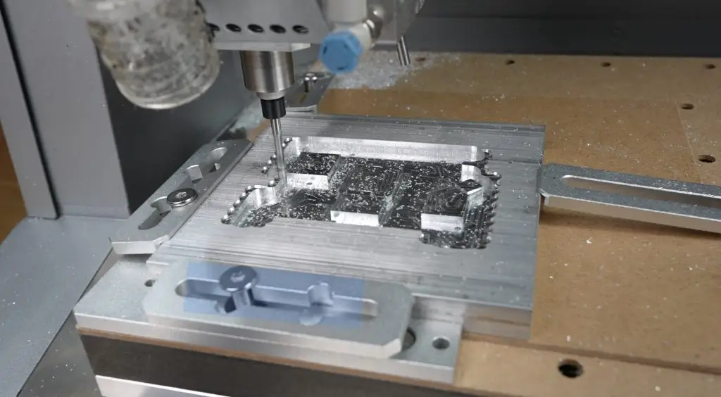
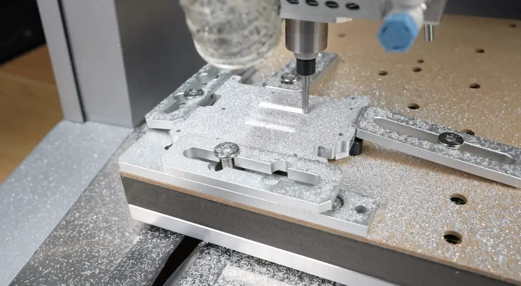
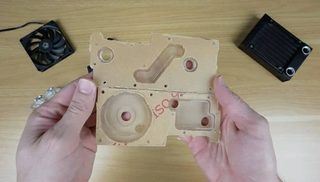
The final result came out great—especially for a desktop CNC. This was my first time milling aluminium, and while there are visible tool marks, the surface finish is smooth and clean.
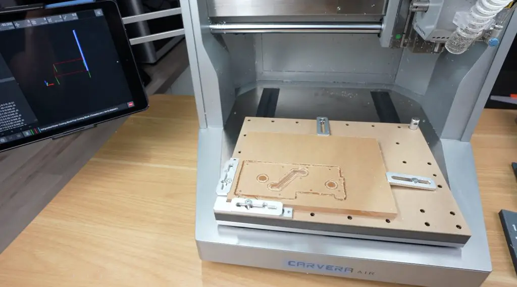
Next up was the acrylic distribution plates, milled from 10mm clear cast acrylic. The first plate was machined with:
- A 2mm flat endmill for the o-ring groove,
- A 1/8″ endmill for the pump cutout and screw holes,
- Pocket milling and outer contours.
The second acrylic layer followed a similar process, with the addition of thread milling using an M4 tool to tap the four pump mounting holes. I then countersank the screw holes using a chamfer bit.
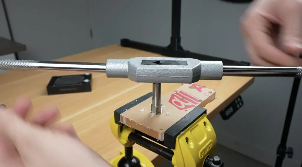
The final step was threading the inlet and outlet ports by hand using a 1/4″ BSP tap. Makera currently offers thread mills in some metric sizes, but a BSP-compatible tool could be sourced elsewhere. I also tapped the M2.5 and M3 holes in the aluminium base at this stage.
Assembling the Waterblock
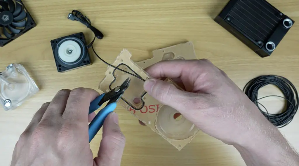
Assembly of the waterblock started with creating four custom o-rings using 1.5mm cord that I cut and joined with super glue. These will seal the aluminium base, distribution channel, and inlet/outlet ports.
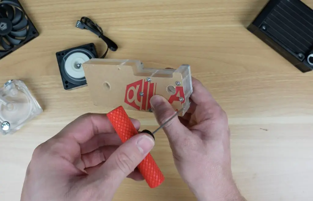
Once the seals were in place, I clamped the acrylic plates together. One side is secured with M3 screws, and the other side is held by the pump itself. The pump is a compact 12V model whose geometry I had replicated in CAD. After inserting the base and impeller, I fixed it in place with four M4 screws.
With the block assembled, I moved on to completing the rest of the loop.
Hardline Tubing and Radiator Setup
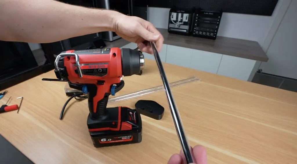
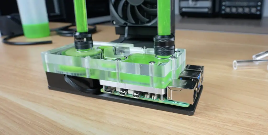
To dissipate the heat from the waterblock, I added an 80mm aluminium radiator connected via 12mm hardline tubing. Despite never working with hardline tubing before, a bit of trial and error yielded some good results. A Milwaukee heat gun did the job, though it lacked a trigger lock, which made things trickier.
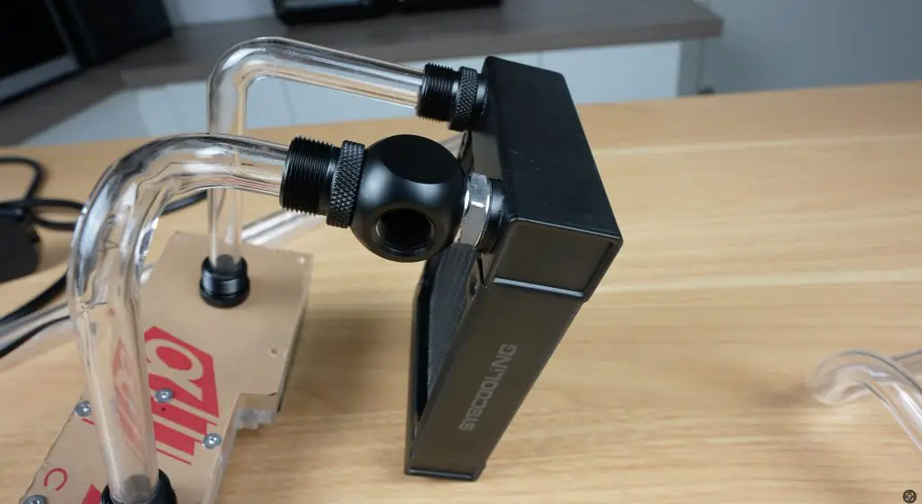
To add a fill port cleanly, I used a compact tee on one of the radiator ports. This provided a simple and tidy way to fill the loop without adding unnecessary bulk.
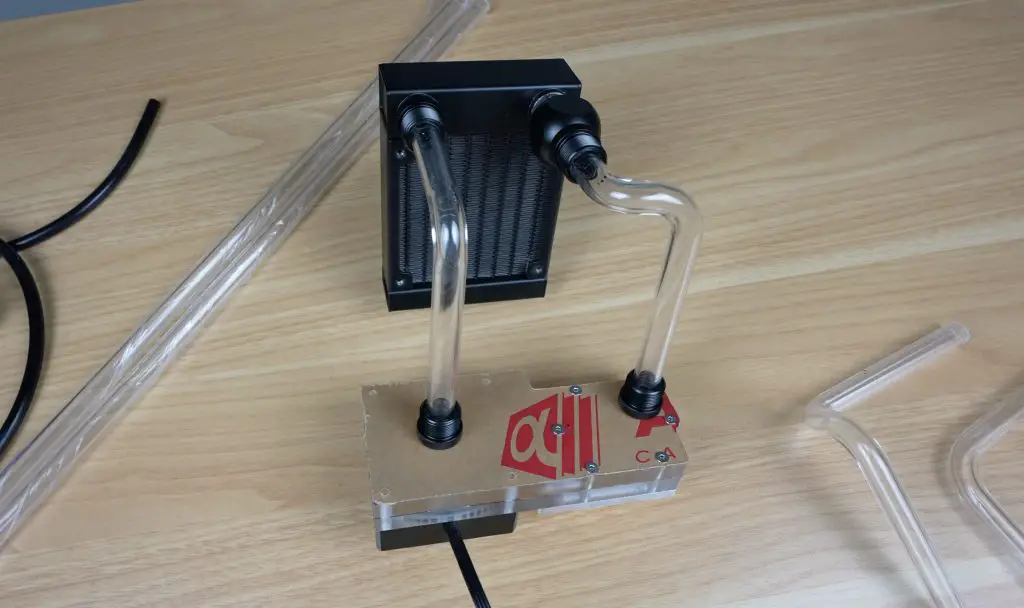
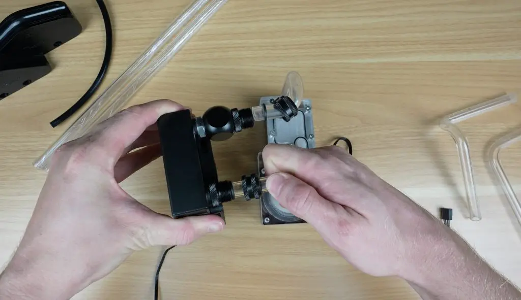
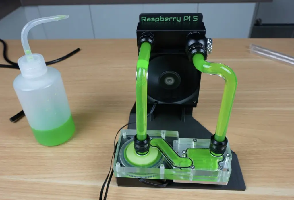
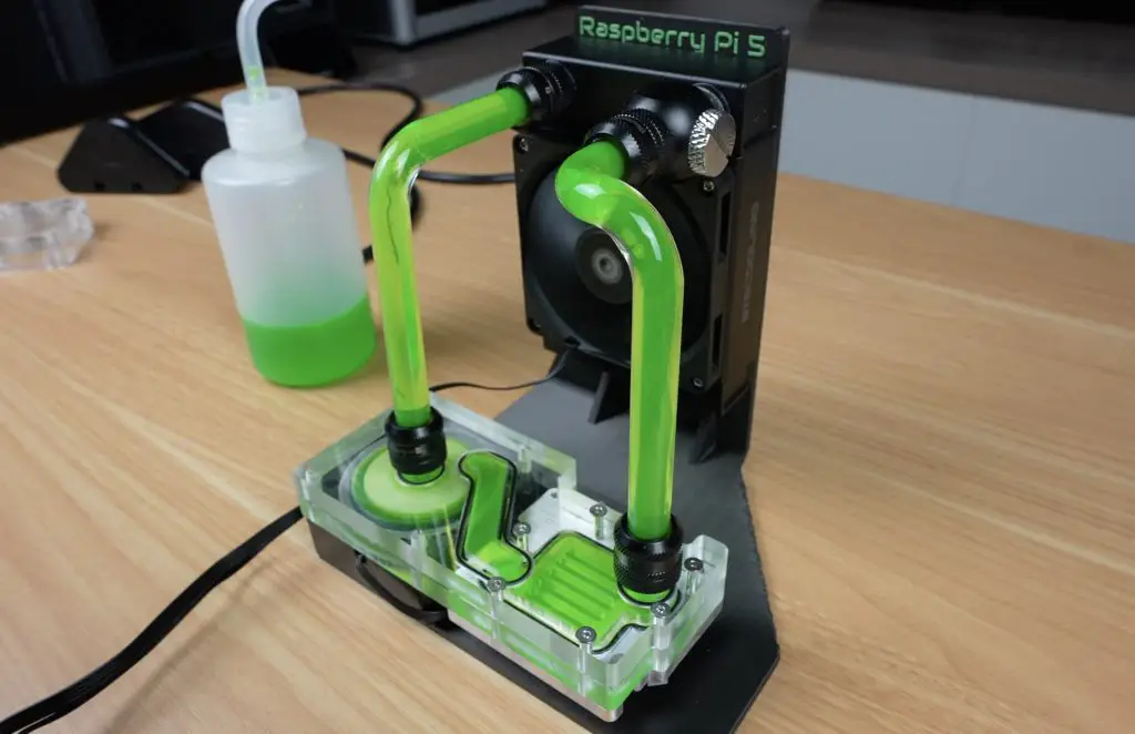
After tightening all the fittings on the waterblock and radiator, I mounted the entire assembly onto the 3D printed stand.
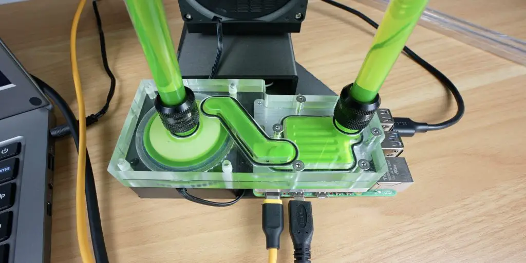
Filling the loop was surprisingly satisfying, especially with the fluorescent green coolant.
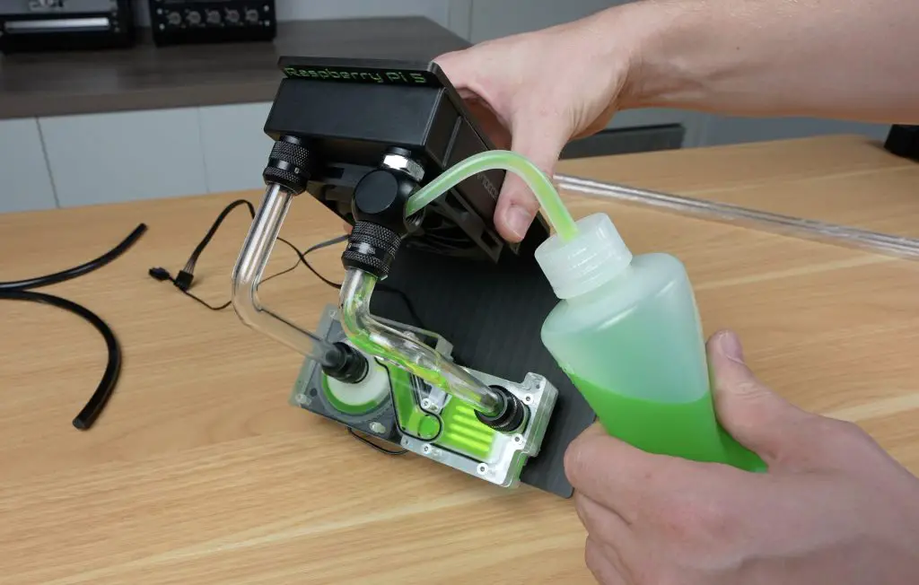
The pump and fan are powered via an adjustable 12V power supply, which lets me tweak their speeds for noise control. There’s no reservoir in the system, so working out the air bubbles took some patience. But the compact design made it worth the effort.

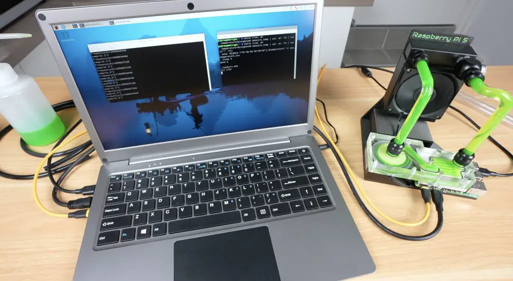
Installing the Pi and Testing the Waterblock
Once the loop was running smoothly and leak-free, I installed the Pi 5 onto the block. I used thermal paste for the CPU and 1mm thermal pads on the other components. I designed the heat sink pads to sit 0.8mm below the components to allow compression and ensure solid thermal contact.
The Pi mounts securely with four M2.5 screws.
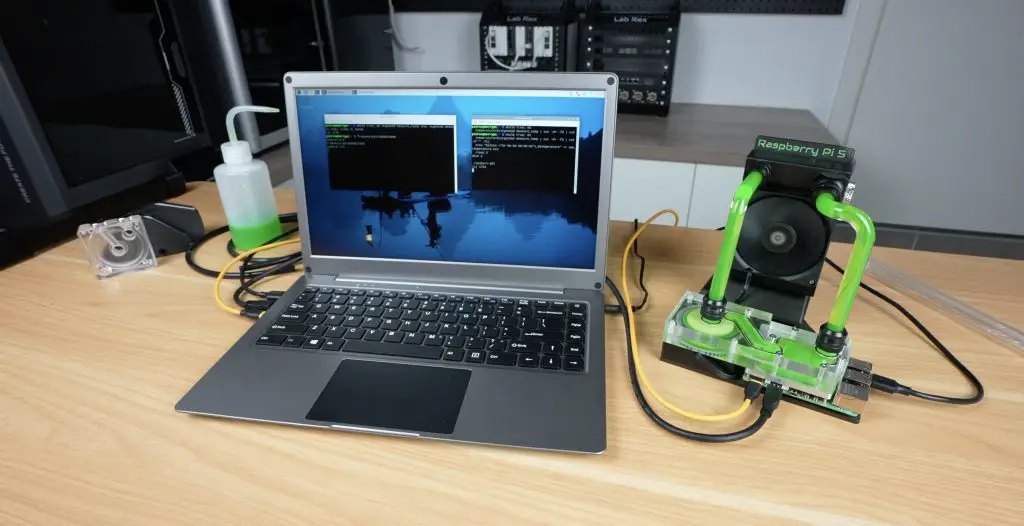
Time to answer the big question, does it actually work?
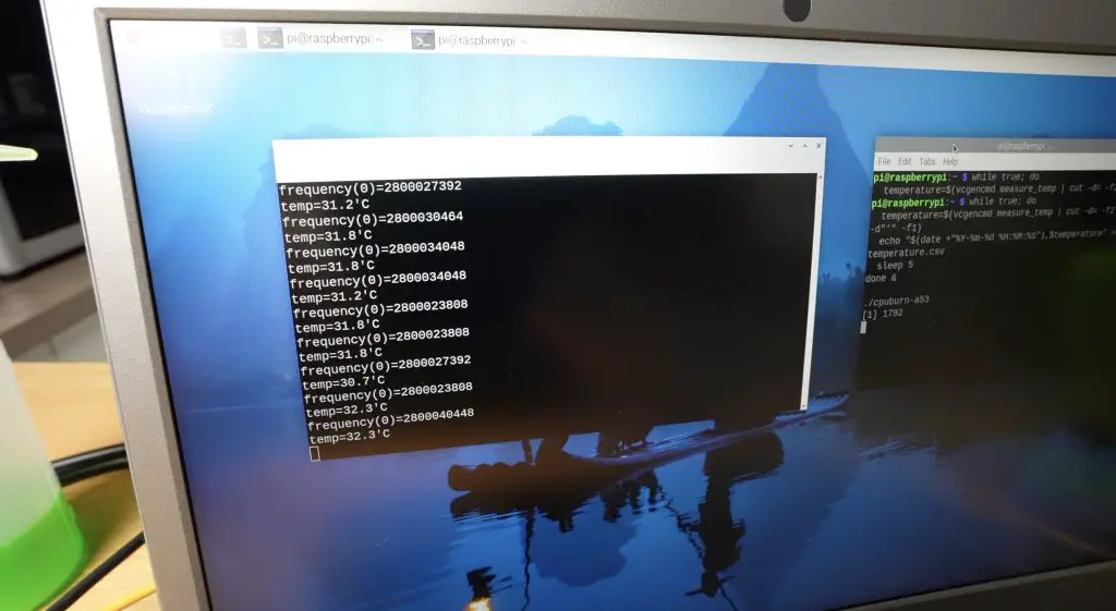
With everything powered up, I ran CPU Burn to stress the Pi’s CPU. It was overclocked to 2.8GHz (up from the stock 2.4GHz) to push the cooling system to its limits.
To start with, we need a baseline. I ran the same test on the same Pi 5 without any cooler and then again with the official actove cooler and got the following results;
- Stock Pi at 2.8GHz (no cooling): it started with a base temp of 44°C and started thermal throttling in under 30 seconds.
- With the Active Cooler: it started at 37°C and peaked at 68°C after 5 minutes.
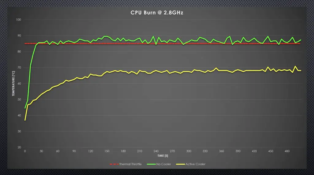
So the Active Cooler does a fair job at keeping the overclocked Pi cool but it still gets quite warm.
I then moved on to testing the Pi 5 in my new custom loop;
With this custom loop: base temp of 24°C (just 3°C above ambient), peaking at 32°C under full load. That’s a full 36°C drop compared to the stock unit and 5°C cooler than the active fan solution at idle.
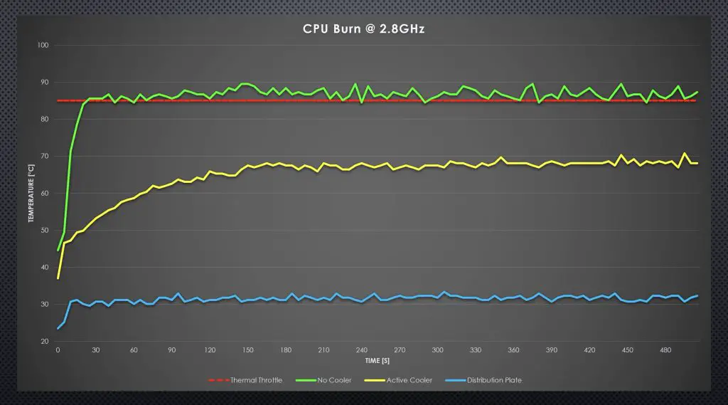
The oversized aluminium block made a big difference by directly contacting the CPU heat spreader. With so much thermal headroom, I was also able to lower the pump and fan voltage for quieter operation without sacrificing cooling performance.
Final Thoughts
This was definitely an over-the-top build—but that’s what made it so much fun. It was my first time building a distribution plate and working with hardline tubing, and both exceeded expectations. The Carvera Air handled the aluminium and acrylic with ease and gave me confidence in taking on more CNC-based projects.
If you’re interested in trying something like this yourself, I highly recommend checking out the Carvera Air on Makera’s website.
If you enjoy projects that combine CNC machining, 3D printing, and pushing small single-board computers to the limit, subscribe to my Youtube channel or follow my blog. Feel free to leave a comment down below on what you’d like to see water cooled, or what I should build with the Carvera Air, next!
Awesome build! Any chance you can make the files for the aluminium block and acrylic distribution plate available somewhere?
Agreed! I’ve been working on milling something similar and struggled a bit with depth of scut and speeds. I would love a copy of your G3’s file that includes the CAM operations.
Hardly overkill when you consider the results.
Put the kit on your Etsy!