If you’re into testing and experimenting with Raspberry Pi accessories, then you’ll know the importance of a solid setup that’s both functional and accessible. In today’s post, I’ll walk you through the design and build process for a custom open-air Pi test bench tailored for the Raspberry Pi 5. It’s complete with a real-time stats display, RGB CPU load monitor, and push-button controls.
Here’s my video of the build, read on for the written guide;
What You Need To Build Your Own Pi Test Bench
- Raspberry Pi 5 – Buy Here
- Pi 5 Active Cooler – Buy Here
- Pi 5 NVMe Hat – Buy Here
- Pi 5 NVMe Hat Extension Cable – Buy Here
- Lexar NM620 NVMe Drive – Buy Here
- M2x10mm Button Head Screws – Buy Here
- M2.5 Brass Standoffs – Buy Here
- M2.5 Button Head Screw Set – Buy Here
- I2C OLED Display – Buy Here
- RGB LED – Buy Here
- Tactile Pushbuttons – Buy Here
- Female Breadboard Jumpers – Buy Here
Tools & Equipment Used:
- Makera Cavera Air – Buy Here
- Carvera Air Bits – Buy Here
- USB C Screwdriver – Buy Here
- Bambulab P1S Combo – Buy Here
- FNIRSI Soldering Iron – Buy Here
Some of the above parts are affiliate links. By purchasing products through the above links, you’ll be supporting this channel, at no additional cost to you.
Why Build a Raspberry Pi Test Bench?
The idea was to create something better than a simple Pi stand. I wanted something that looks great on a desk but is also practical for testing different HATs, accessories, and custom configurations. I needed a setup that would allow easy access to the Pi’s components while offering flexibility for cooling and external add-ons.
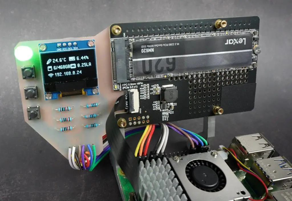
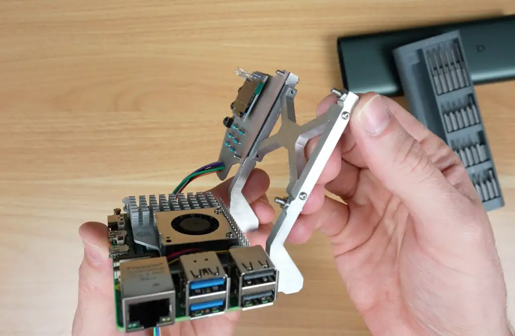
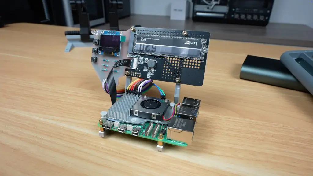
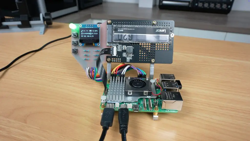
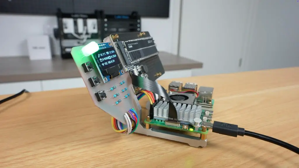
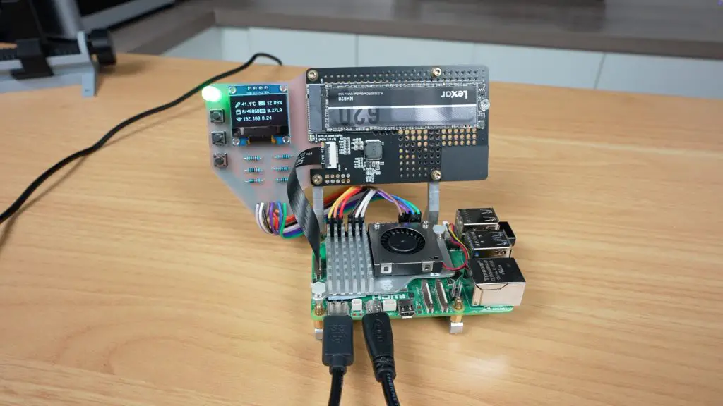
The result is a two-level stand with the Pi 5 on the base and a mounted HAT above it, making everything clean and organized while remaining functional. I still have access to the Pi’s GPIO pins and have a clear area above the Pi to fit a range of coolers.
Designing the Stand in Fusion 360
I started out in Fusion 360, designing the stand to hold a Raspberry Pi 5 flat on the desk and a HAT mounted above at an angle. The angled top mount can accommodate various add-ons like NVMe adapters or AI accelerators. You can still add external coolers and peripherals, which would be difficult with a HAT sitting directly on the Pi.
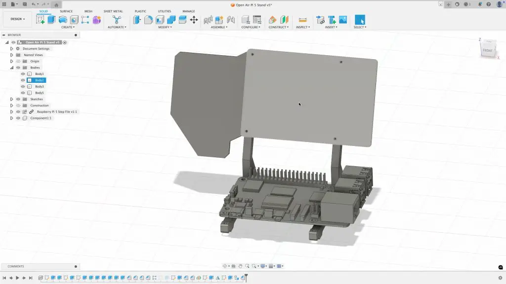
The stand was designed to be milled from aluminium for durability and aesthetics, but it can also be 3D printed. Alongside the main frame, I designed a small custom PCB that adds an OLED screen, RGB LED, and three programmable buttons to the mix.
Here are the 3D Print Files if you’d like to try print out your own stand.
Designing the Control PCB in EasyEDA
The control board was designed using EasyEDA, a free online PCB design tool.
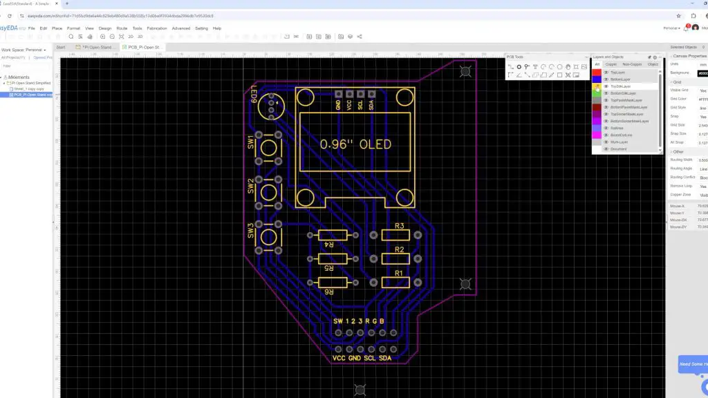
Despite its small size, the PCB brings a lot of functionality:
- OLED Display: Shows IP address, CPU temperature, and system resource usage.
- RGB LED: Changes colour based on CPU load—green for idle, red for max load.
- Three Pushbuttons: Mapped to custom actions like running scripts, toggling services, or rebooting.
All of this connects neatly to the Pi’s GPIO header via a short lead.
Here are the PCB gerber files if you’d like to make your own PCB;
Manufacturing the Components with the Carvera Air
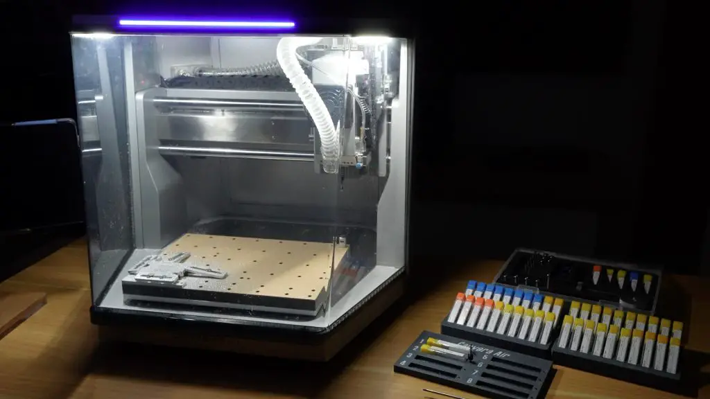
To fabricate the components, I used the Carvera Air, a compact desktop CNC that Makera sent me to try out. I already had one from their Kickstarter campaign last year, so this expands on my workshop capabilties.
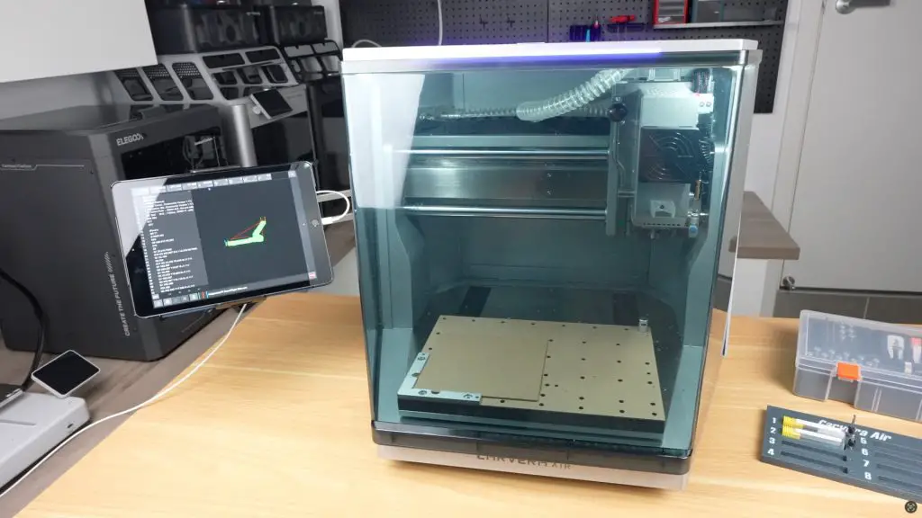
The Carvera Air is a versatile machine that can:
- Mill wood, plastic, and aluminium
- Laser engrave
- Fabricate PCBs
So it’s a great addition to a home workshop or Makerspace.
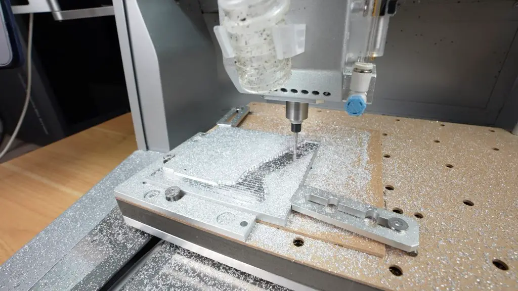
Milling the Aluminium Parts
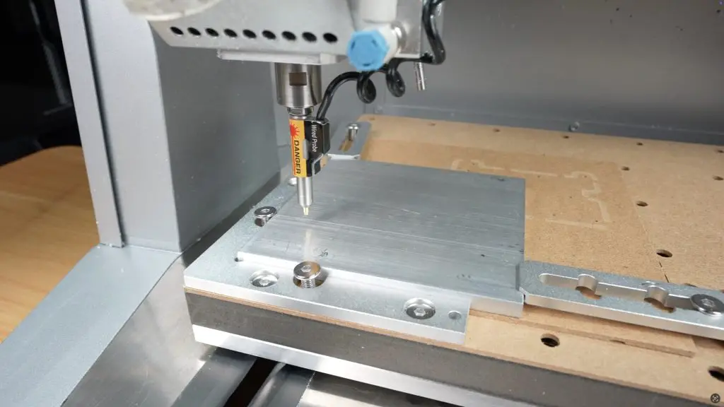
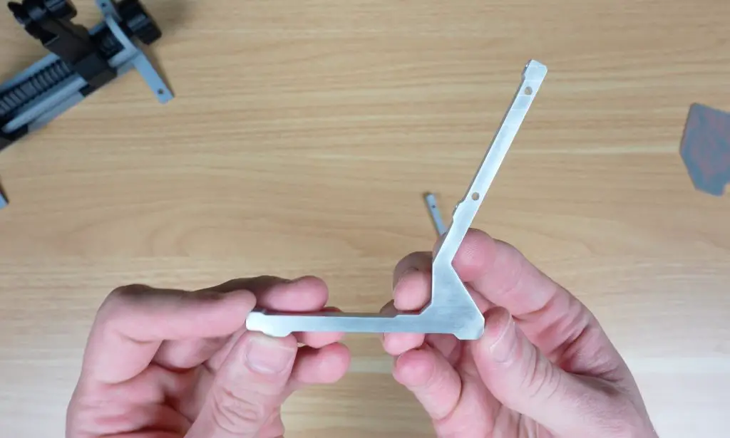
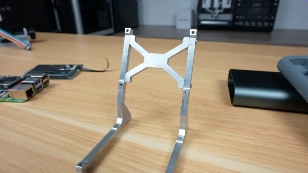
I began by milling the three aluminium pieces for the stand, the two identical sides and the central joiner.
First up, we need to create the tool paths for each operation required to make up each part. I did this in Fusion360’s manufacturing space. This also allows you to add virtual stock and simulate the paths that are created.
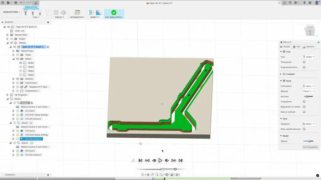
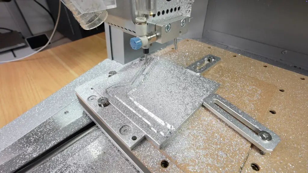
To make up the first leg, the Carvera Air performs autolevelling by probing the surface. I then used a 1/8″ endmill to face the parts. Then drilled holes using a 2mm drill bit for the joiner connection and finally, used the same endmill to contour the parts.
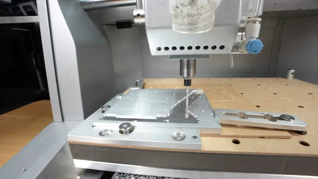
Tabs hold the parts in place during milling and need to be removed and cleaned up afterwards, but overall I’m really impressed by how well it came out.
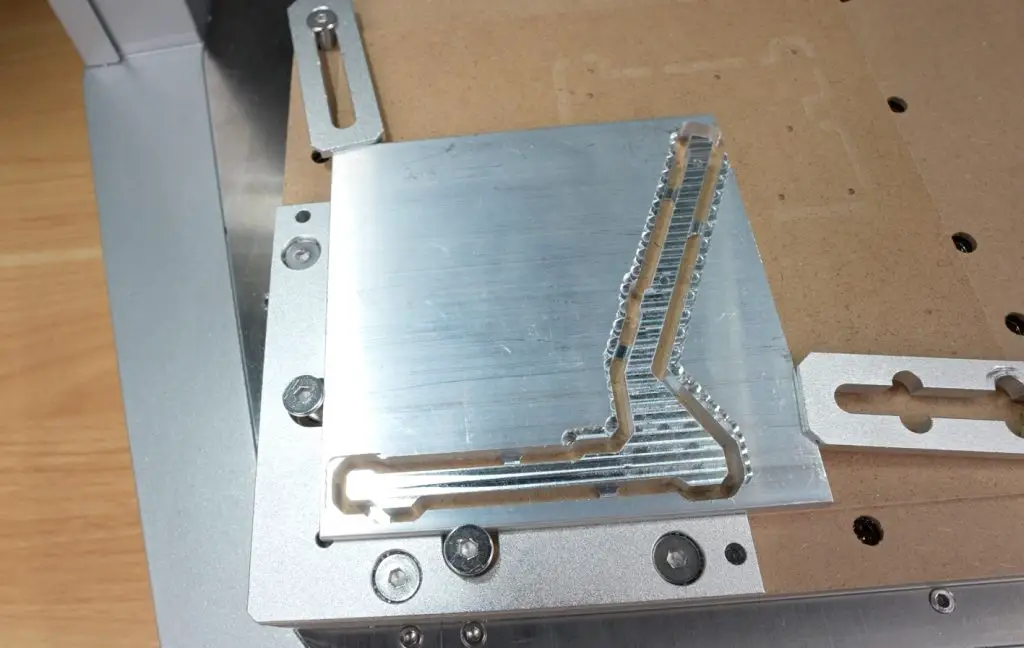
We then need to repeat the process for the second leg and make up the joiner too.
Making the PCB
The PCB was also fabricated using the Carvera Air using their PCB Fabrication Pack.
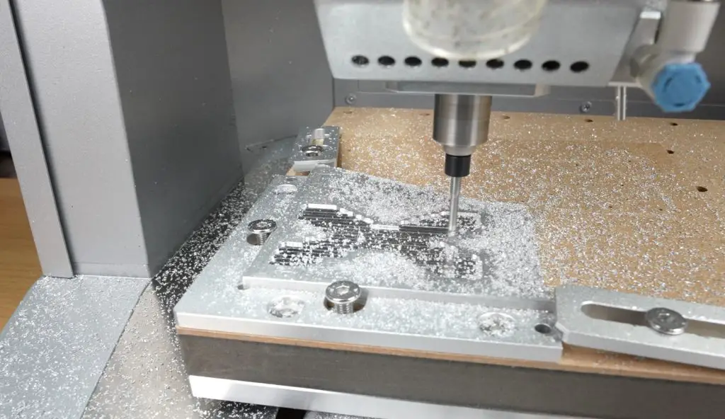
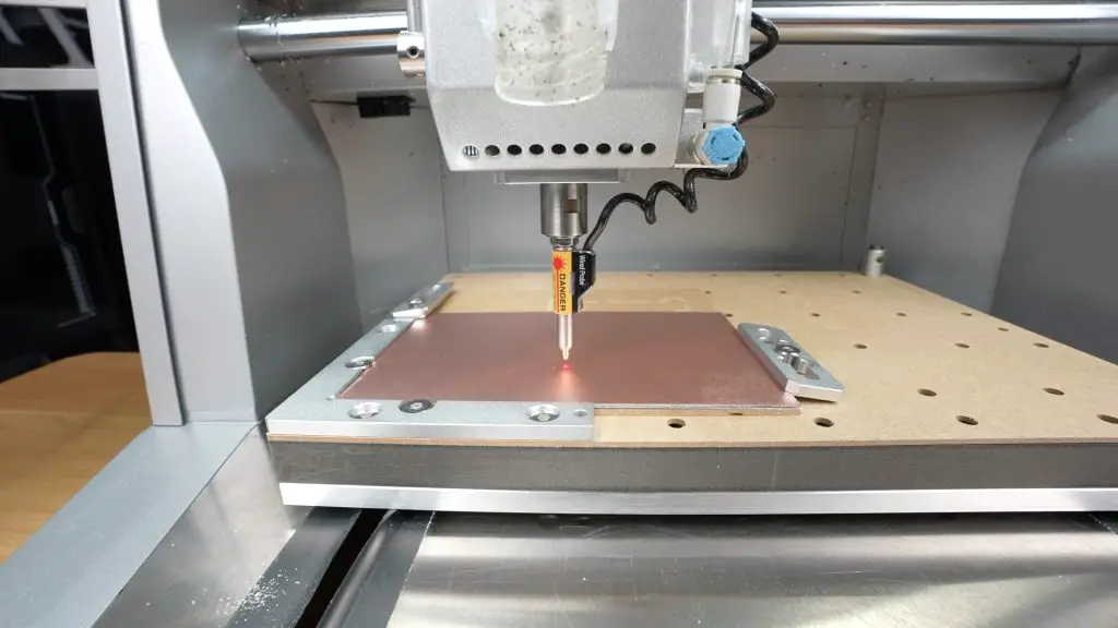
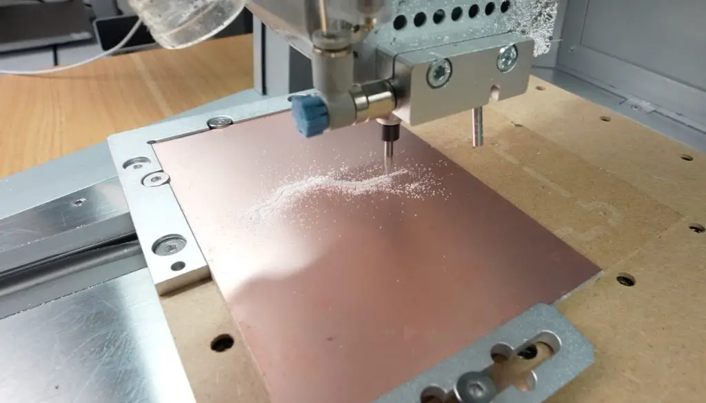
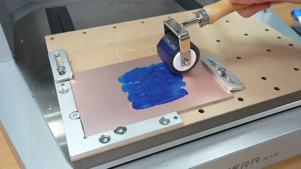
This is a simple PCB, so it only requires a single-sided PCB blank. The Carvera Air again starts out by probing the surface of the blank so that it’s able to accurately engrave the traces.
The traces are then engraved using a 0.2mm engraving bit.
UV-curing solder mask is then applied and cured for 10-15 minutes using a UV lamp.
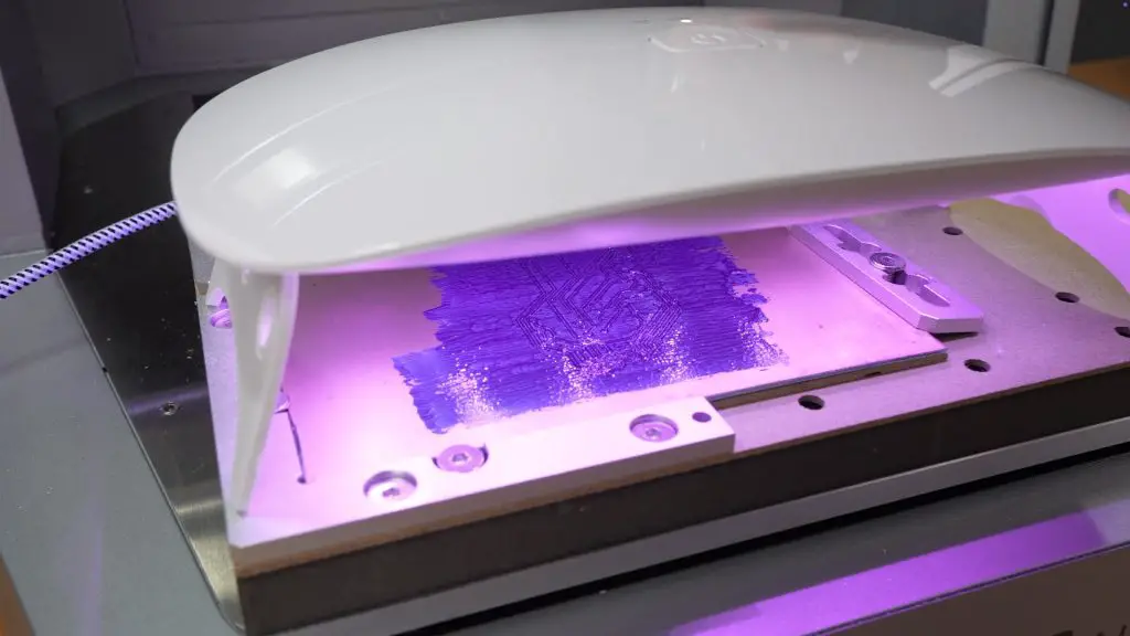
In hindsight, I probably put a bit too much UV mask on in each layer, so the finish isn’t great and it took a long time to cure between layers. It was first time using the solder mask and the end product doesn’t look too bad, it’ll be on the back in any case.
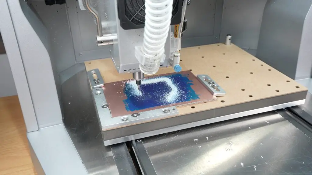
The solder mask is then removed from the pads that we’re going to solder onto using a mask removal tool. Then holes were drilled for the through-hole components with a range of drill bits.
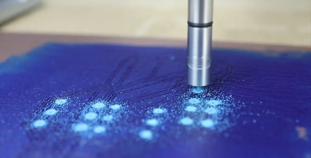
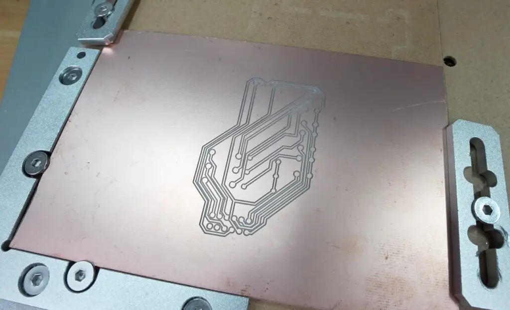
Finally, a 0.8mm corn bit was used to cut out the board. Tabs again hold it in place, which will need to be removed and cleaned up afterwards.
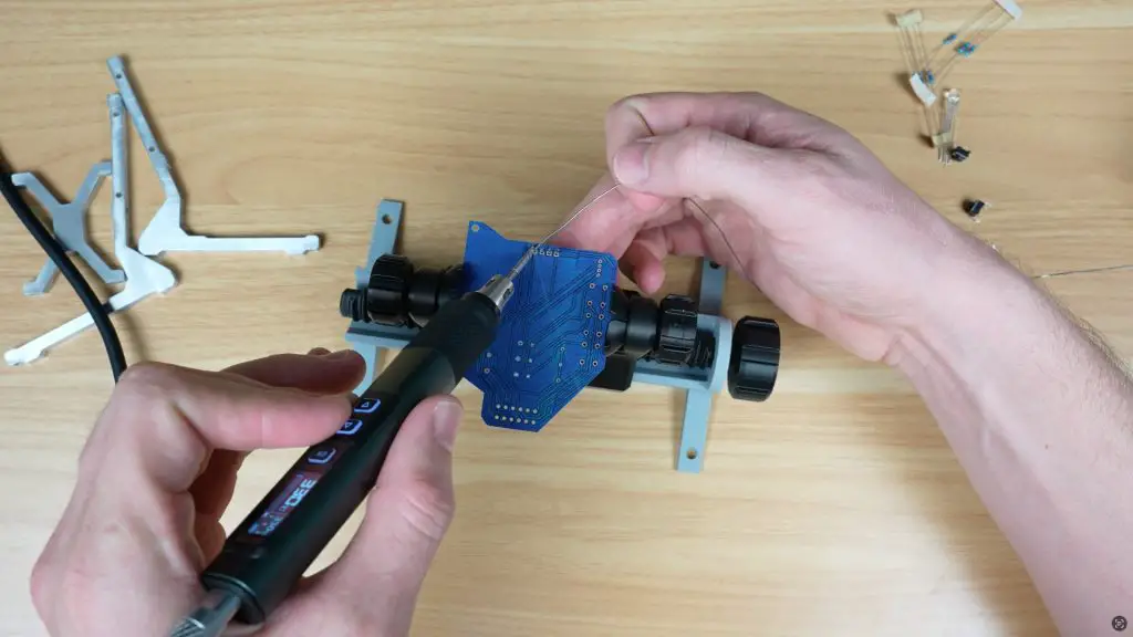
The PCB components, OLED screen, RGB LED, resistors, and tactile switches, were then soldered into place.
Assembling the Test Bench
With all the components fabricated, it was time to assemble the Pi test bench.
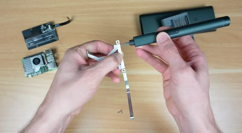
I started out by tapping M2 holes in the joiner to bolt the aluminium sides to.
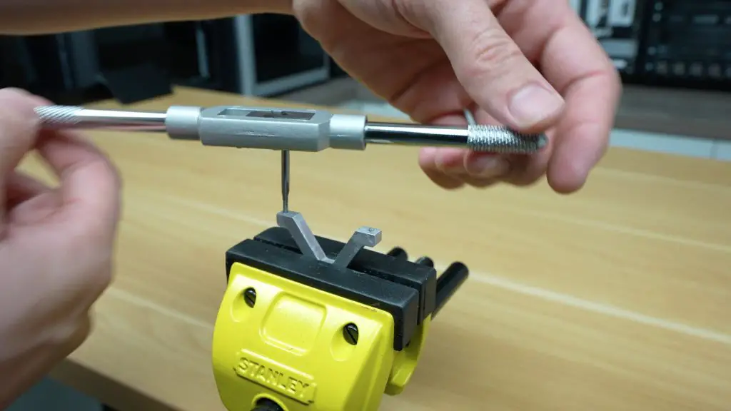
Four M2x10mm button head screws hold the legs onto the sides of the frame.
Next we need to mount the Pi. Four M2.5x6mm standoffs are used to hold the Pi securely. These can be installed with way around – I prefer having the threads facing upwards so that the Pi can just be placed onto them.
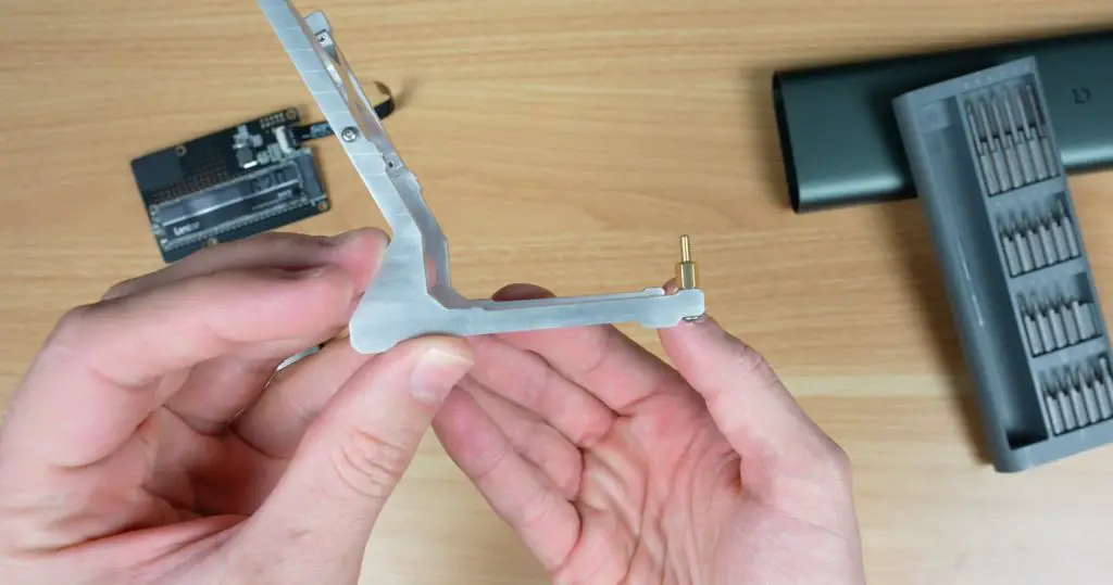
Brass inserts served as thumb screws, making it easy to remove and reattach the Pi without tools.
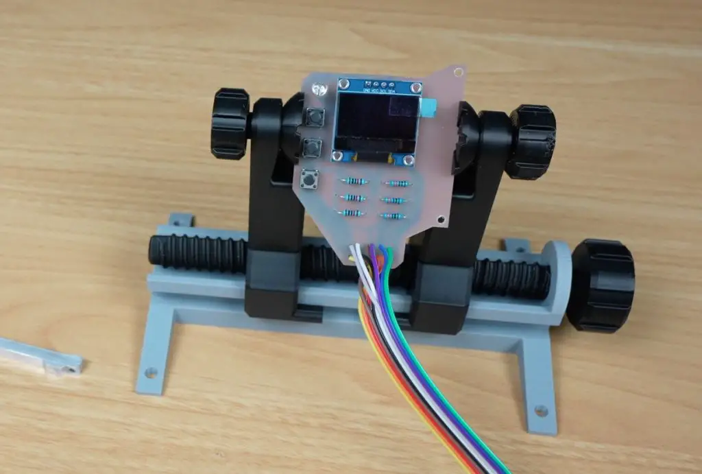
For the HAT, I mounted it directly to the frame using some M2.5x12mm button head screws and M2.5 nuts, since the NVMe HAT I used had no bottom-side solder joints. These same screws hold the control PCB securely in place alongside the hat.
Real-Time Monitoring and Controls
With the Pi test bench now complete, we can load the stats script onto the Pi and start using it.
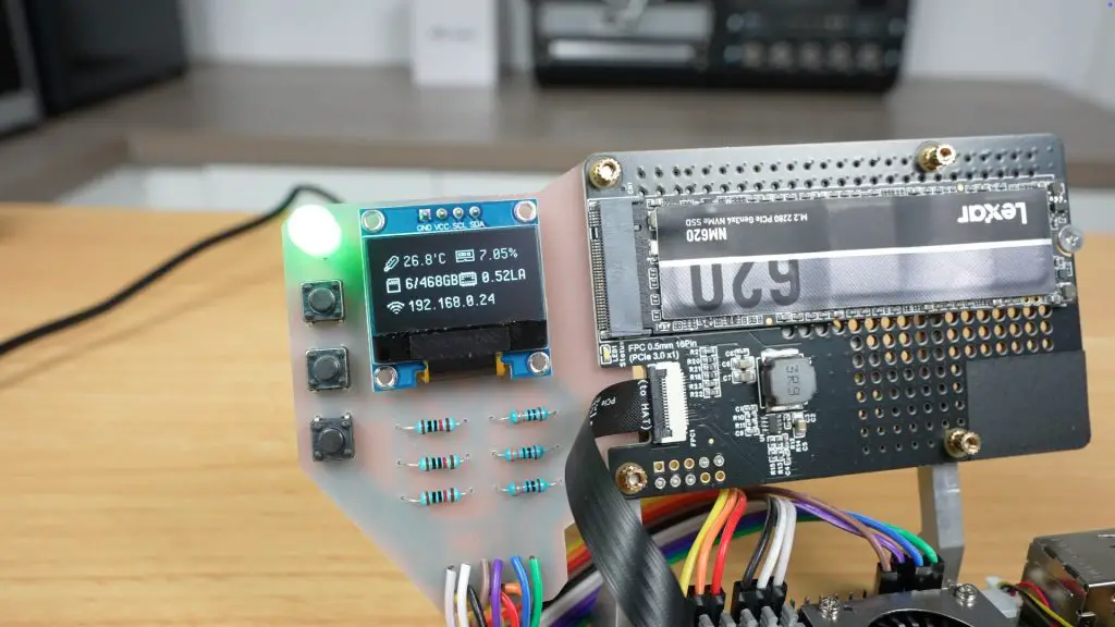
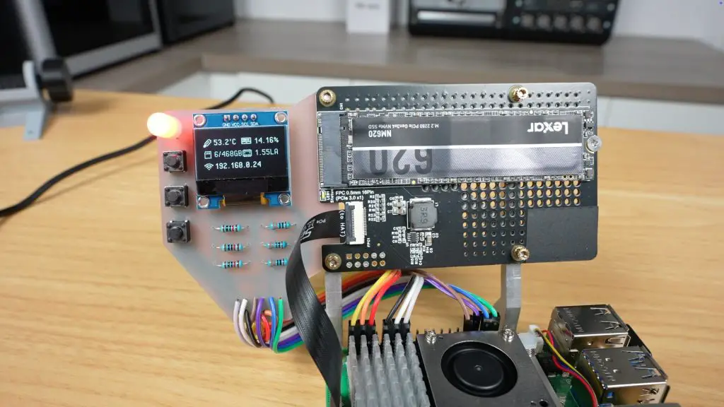
The OLED display shows live system stats including the Pi’s IP address, CPU load, and temperature and other resource utilisation like RAM and storage.
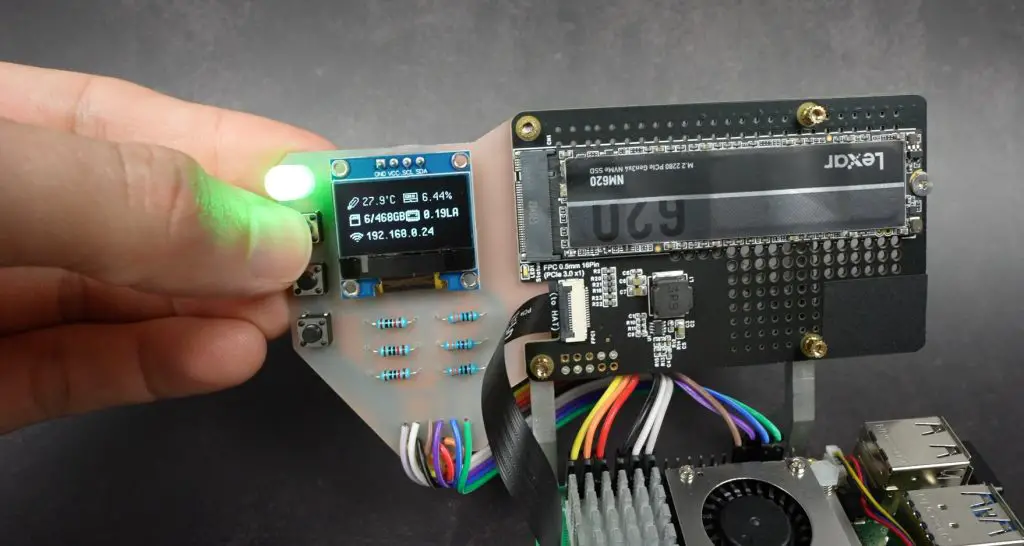
I’ve set the RGB LED up to change from green to red based on CPU load, giving you instant visual feedback at a glance. It’s green when the CPU load is under 5% and then moves through a range of yellow and through to solid red at 100% utilisation.
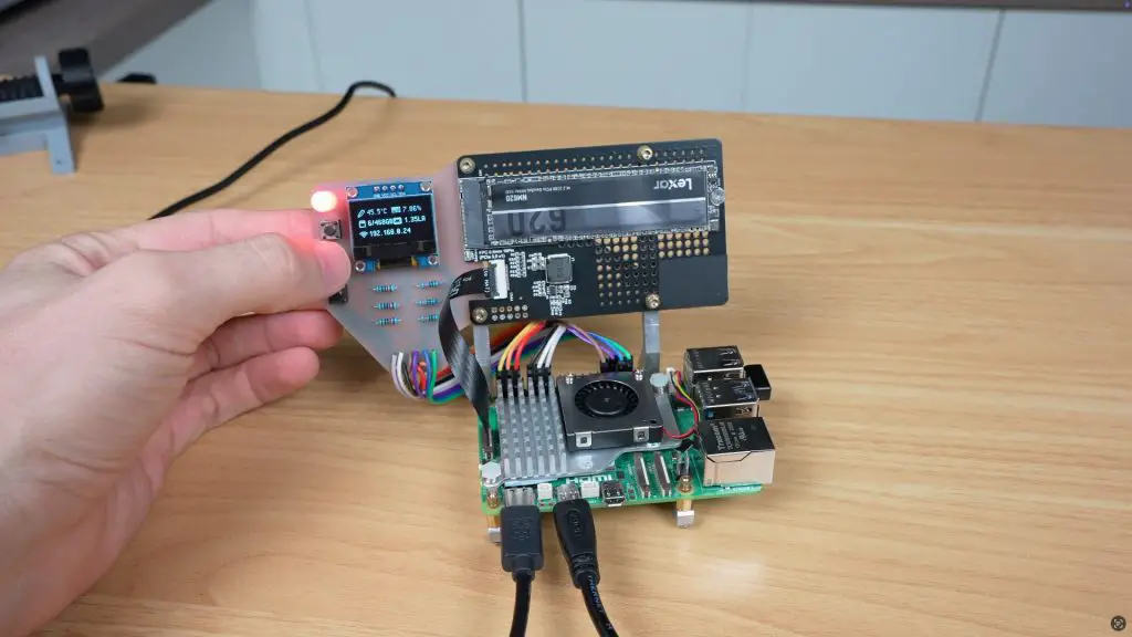
The three buttons underneath the LED are configurable through Python scripts to control services, scripts, shutdowns, or toggling the OLED display, even when the Pi runs headless.
Final Thoughts
The extra weight from the aluminium stand, PCB, and HAT adds stability—preventing the Pi from sliding around when plugging in cables. And let’s be honest, it looks fantastic on my desk.
If you’re into Pi projects, want to test new accessories, or just want a clean, professional bench setup, this project is a great starting point.
Let me know in the comments section below what features you’d like to see added. Maybe an integrated fan controller? More buttons? USB hub?
If this build has inspired you, check out the Carvera Air from Makera. It’s an awesome addition to any workshop, letting you prototype your own PCBs and aluminium components quickly and accurately.
I would be very curious to see your really cool project mixed with your watercooling