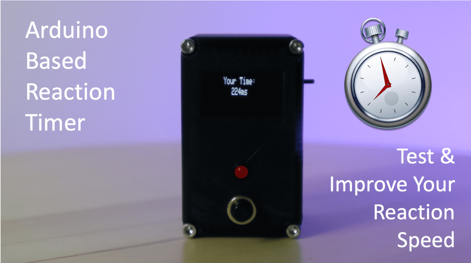
Have you ever wanted to test your reaction time or see which one of your friends has the fastest reaction time? In this project, I’ll be showing you how to build an Arduino based reaction timer. The timer lights up a red LED and then measures how long it takes you to respond to the light by pushing a button. The initial time it takes to turn the LED on is randomised to eliminate guessing and the timer disregards the input if you hold the button down before the LED comes on to stop cheating.
It’s powered by 2 AA batteries and is completely portable, making it a great coffee table or desktop toy to play around with when you’re bored or to challenge your friends and family with.
This project assumes you know the basics of Arduino programming, otherwise read our guide on getting started with Arduino.
Here’s a video of the assembly and the reaction timer being used. Read on for the full step by step instructions, code and 3D print files.
What You Need To Build A Reaction Timer
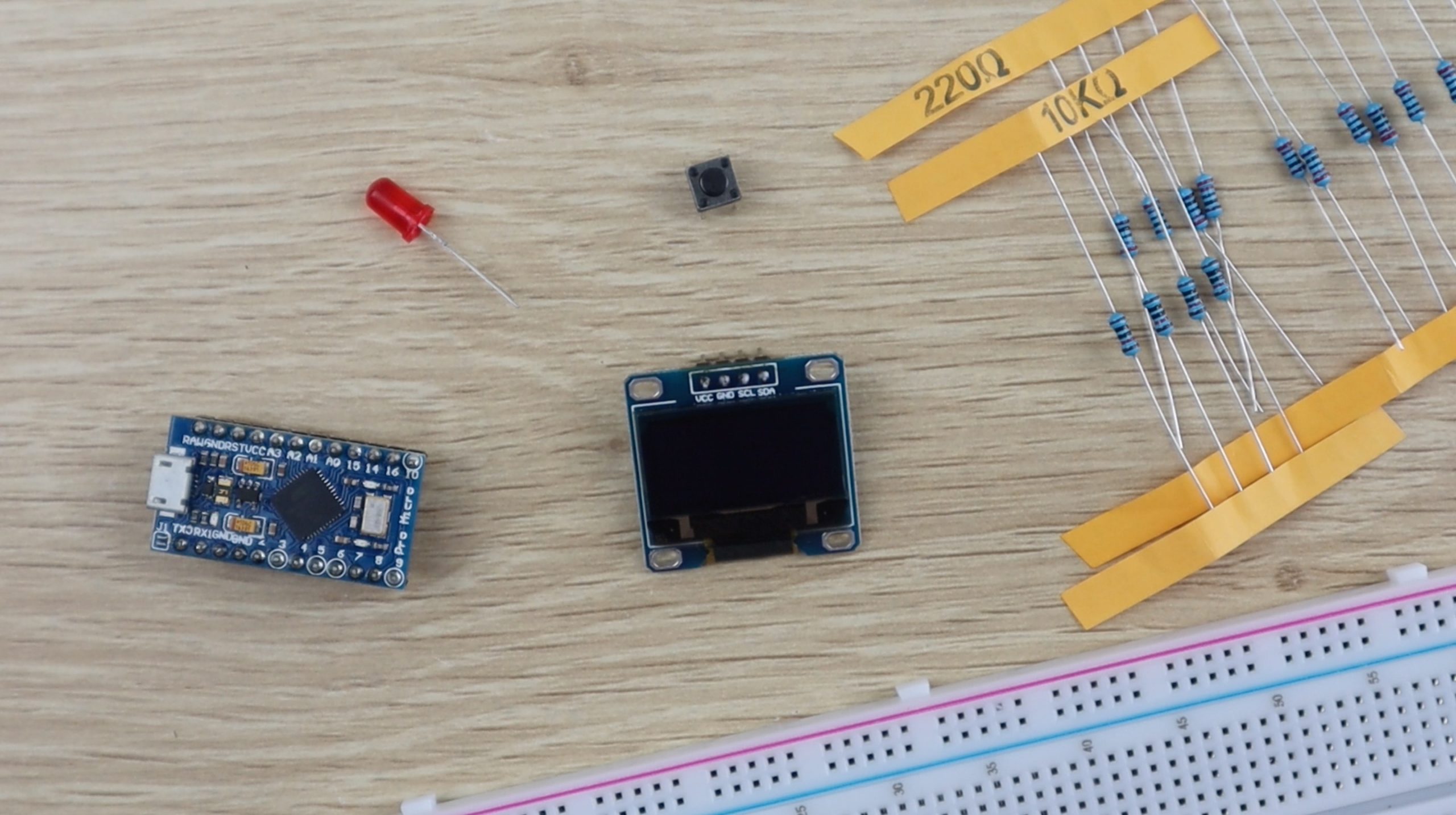
To build a handheld reaction timer, you’ll need:
- Arduino Pro Micro – Buy Here
- OLED Display – Buy Here
- Push Button – Buy Here
- LED – Buy Here
- Resistors (220 ohm & 10K) – Buy Here
- Ribbon Cable – Buy Here
- Male Pin Header Strips – Buy Here
- Female Pin Header Strips – Buy Here
- AA Battery Holder – Buy Here
- Micro Slide Switch – Buy Here
- Cap Screws – Buy Here
If you just want to build the reaction timer on a breadboard then you won’t need the items listed after the resistors, but you will need:
You’ll also need to 3D print some plastic components for the housing. If you don’t already have a 3D printer and you enjoy making things, I recommend you have a look at getting one. They’ve come down in price a lot and you can get one which produces good quality results for a few hundred dollars. If you’re not ready for one then make use of an online 3D printing service, there are loads of them available and they’ll print and deliver the components to your door. This is the printer and filament I used:
How To Make The Reaction Timer
Assemble The Electronic Components
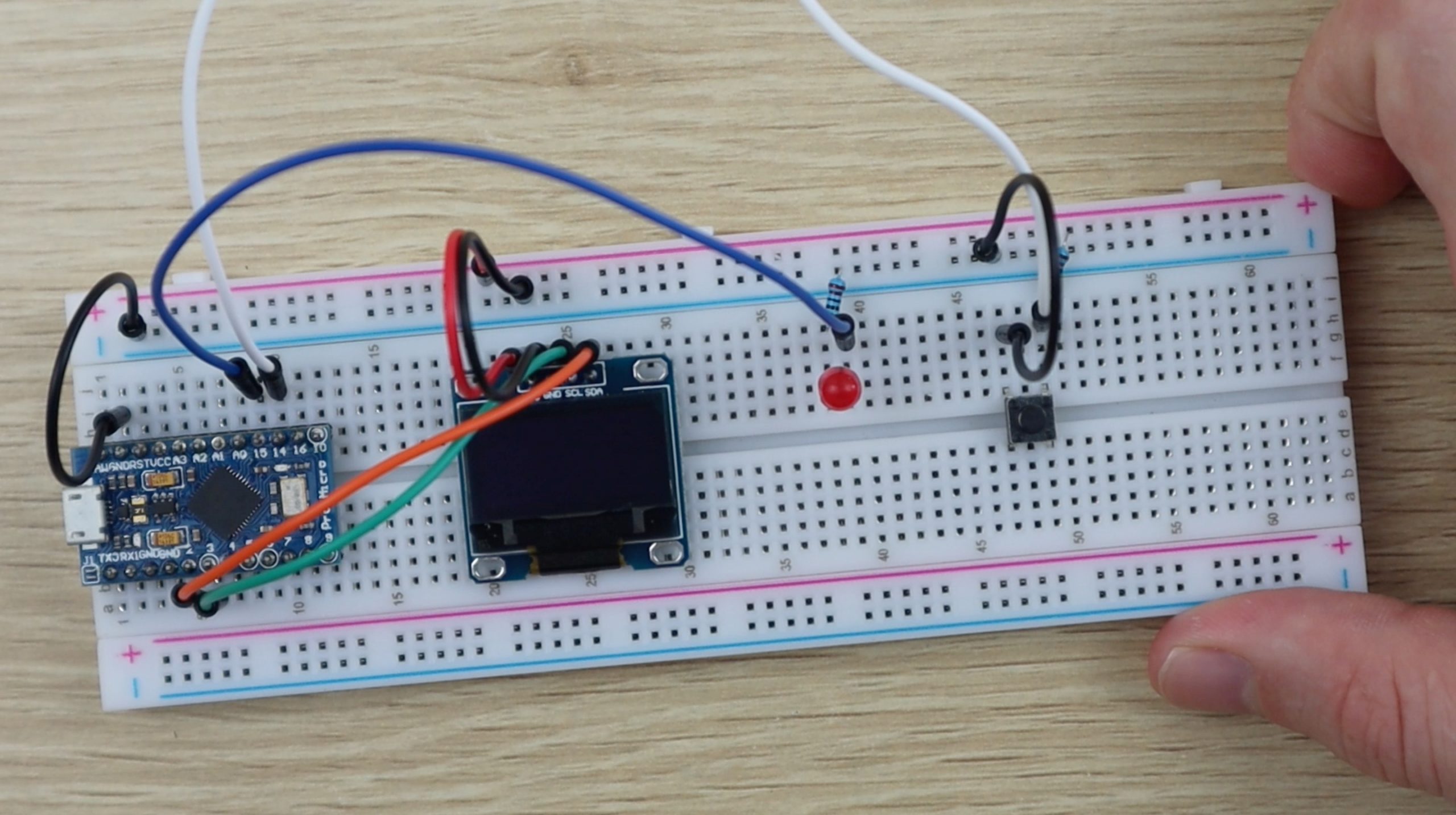
You can assemble the timer on a breadboard using jumpers just for fun or 3D print the enclosure to make it into a more permanent handheld game. I started out on a breadboard to test the circuits and code before assembling them.
Here’s the circuit diagram.
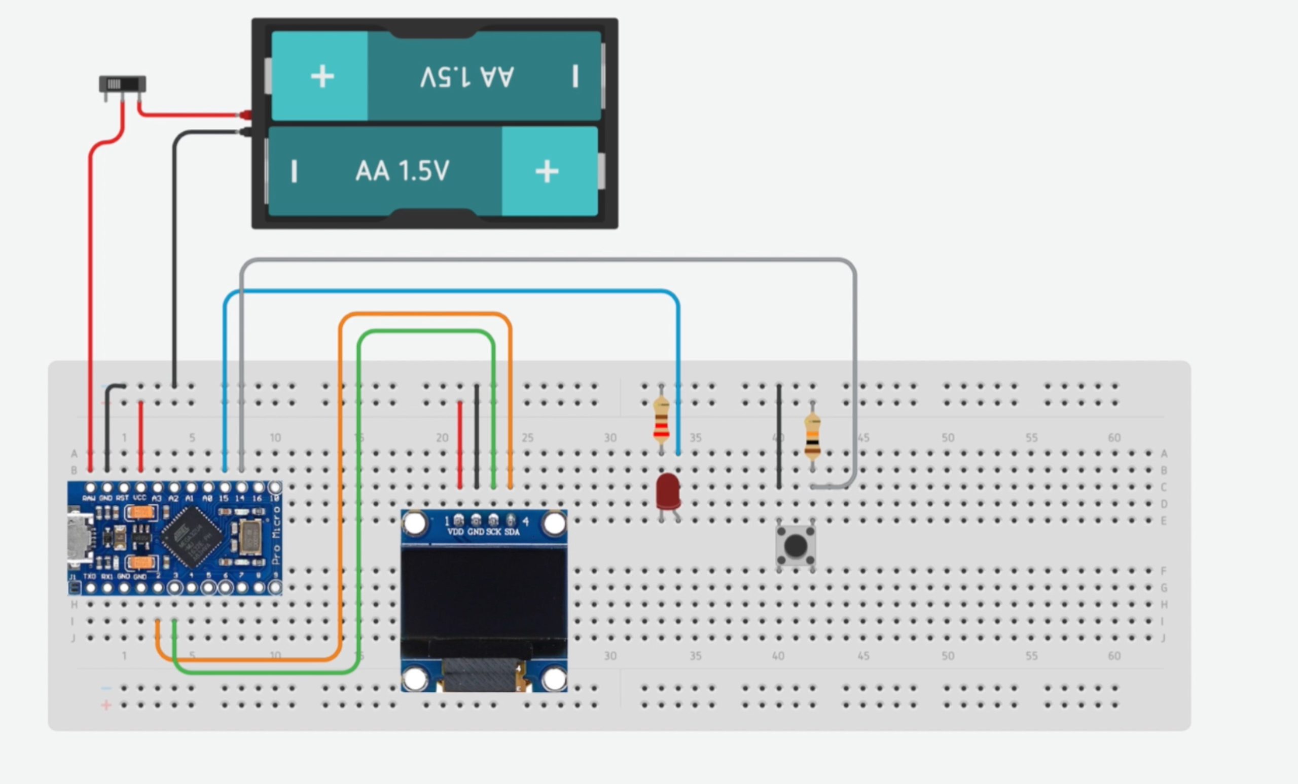
If you’re just assembling the components on a breadboard for fun then you won’t need the batteries, the power supplied through the USB connection to your Arduino Pro Micro is sufficient to power the components.
If you’re using a different Arduino board, make sure that the I2C interface to the display is connected to the correct pins. On the Pro Micro, these are pins 2 and 3, but on an Uno they are pins A4 and A5.
I also wanted to see if the reaction timer could be powered by batteries and how long they would last. I hooked up two AA batteries to supply 3V to the timer and measured the current being drawn.
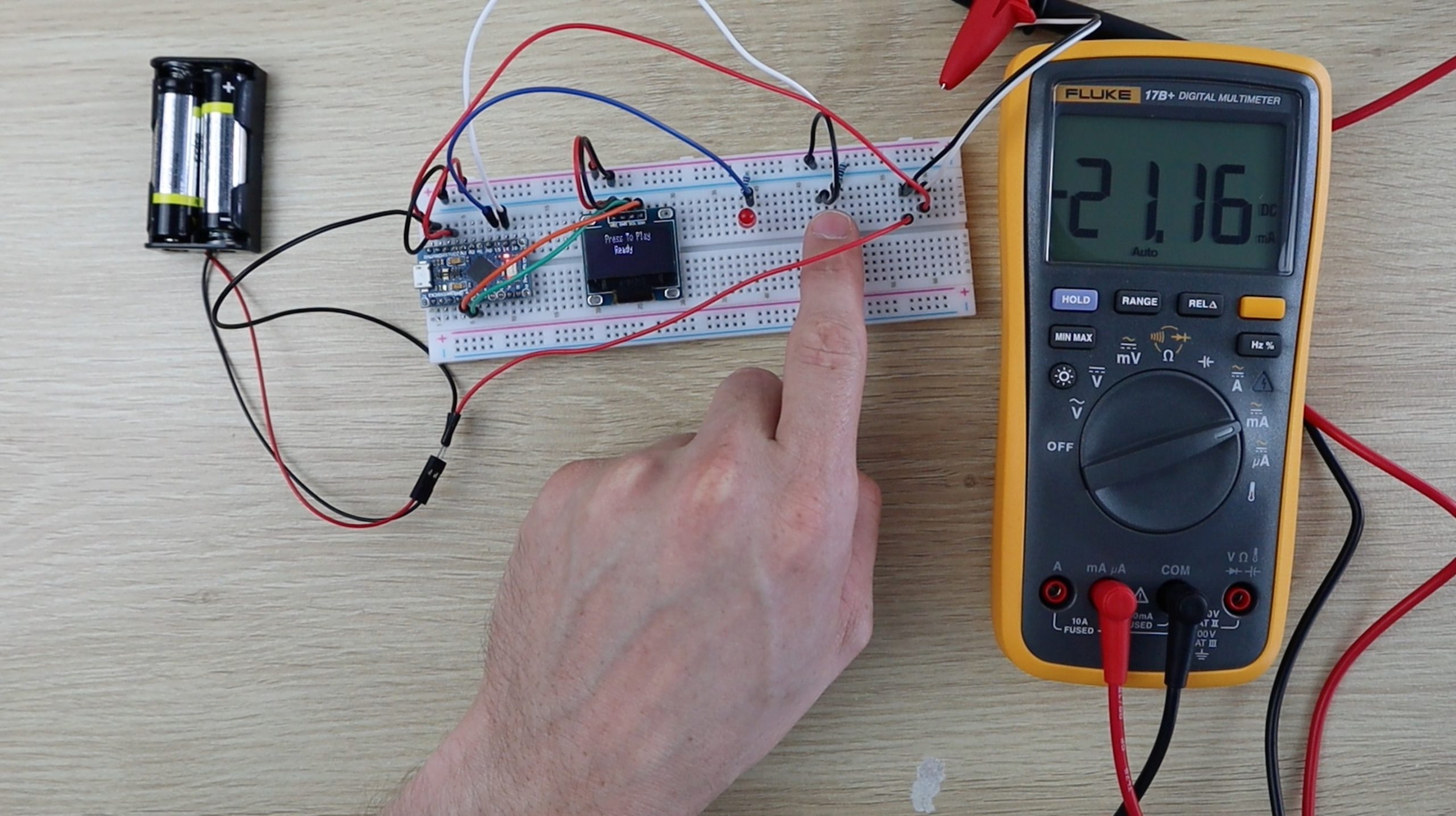
The current fluctuates slightly based on how much text is displayed and it spikes to around 25 milliamps when the LED is on. AA batteries vary quite a lot but by my estimation you should get around 70 to 100 hours of on time from a fresh set of alkaline batteries.
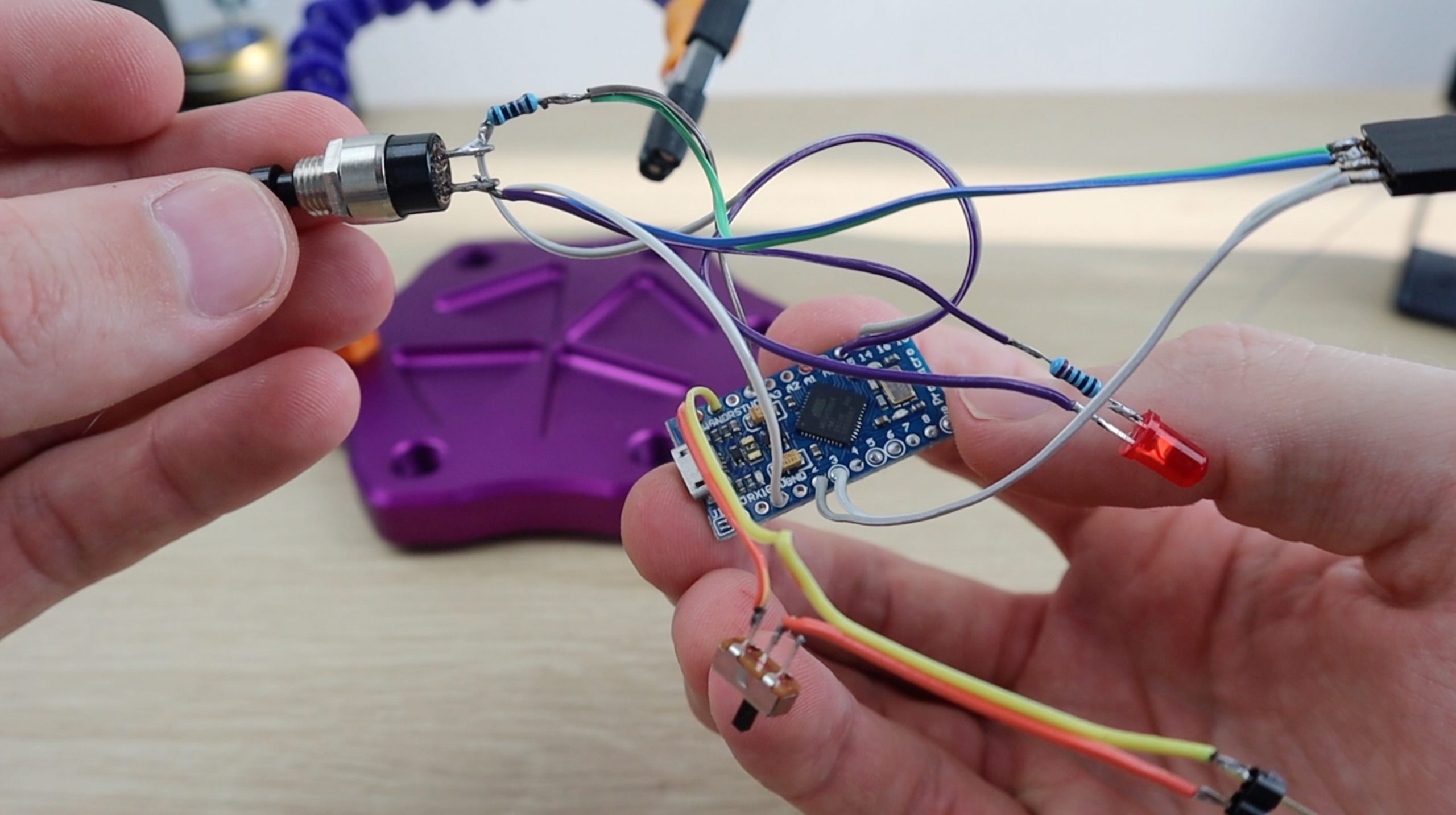
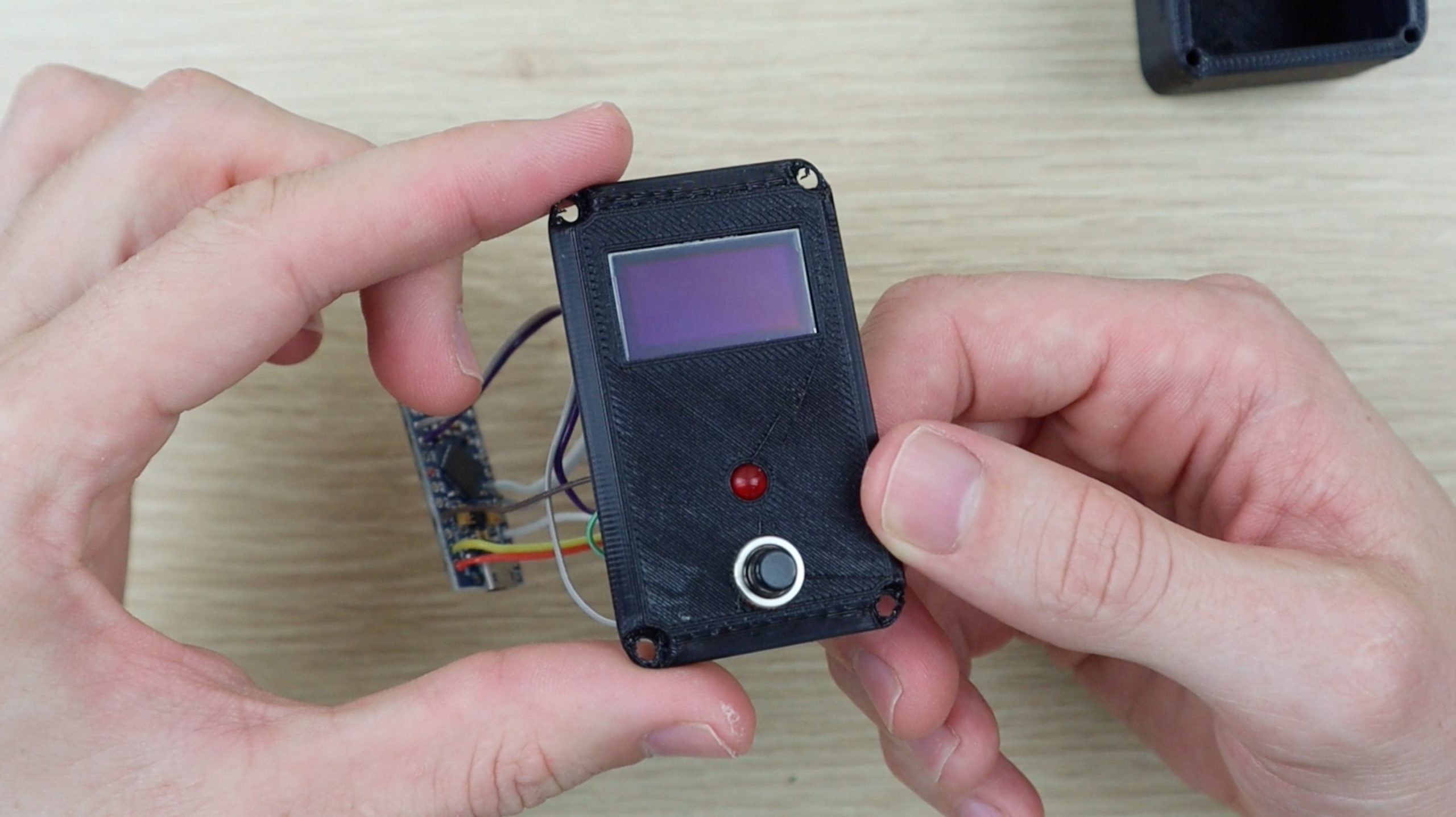
To make the permanent handheld game, I soldered the components together using ribbon cable and some pin headers for the battery and display connections. You can solder these connections as well as they don’t need to be disconnected.
Programming The Arduino
Once you’ve got the circuit assembled, you can load the sketch onto your Arduino and test it.
Lets have a look at the sketch:
//The DIY Life
//Michael Klements
//19 April 2020
#include <SPI.h> //Include the libraries for the display
#include <Wire.h>
#include <Adafruit_GFX.h>
#include <Adafruit_SSD1306.h>
#define SCREEN_WIDTH 128 //OLED display width, in pixels
#define SCREEN_HEIGHT 32 //OLED display height, in pixels
Adafruit_SSD1306 display(SCREEN_WIDTH, SCREEN_HEIGHT, &Wire, -1); //Create the display object
int pinButton = 14; //Define the pins for the Button & LED
int pinLED = 15;
int startTime = 0; //Define variables for the start and end time
int endTime = 0;
void setup()
{
pinMode (pinLED, OUTPUT); //Assign the LED & button pins
pinMode (pinButton, INPUT);
if(!display.begin(SSD1306_SWITCHCAPVCC, 0x3C)) //Start communication with display, address 0x3C for 128x32
{
for(;;); //Don't proceed, loop forever if display communication fails
}
}
void loop()
{
display.clearDisplay();
display.setTextSize(1); //Set the display text size
display.setTextColor(SSD1306_WHITE); //Draw white text
display.setCursor(25,0); //Start at top-left corner, 25 pixels in
display.println(F("Press To Play")); //Display text on screen
display.display(); //Update display
if (digitalRead(pinButton) == LOW) //If button to start game is pressed
{
display.setCursor(40,10); //Display "Ready" countdown with 3 sequential dots
display.print(F("Ready"));
display.display();
delay(1000);
display.print(F("."));
display.display();
delay(1000);
display.print(F("."));
display.display();
delay(1000);
display.print(F("."));
display.display();
int delayTime = random(2000,7000); //Wait a random amount of time between 2s and 7s so that users can't guess the start time
delay(delayTime); //Delay the random amount of time
digitalWrite(pinLED, HIGH); //Light up the LED
startTime = millis(); //Record the start time
while (digitalRead(pinButton) == HIGH) //Wait for the user to push the button
{
}
endTime = millis(); //Record the button push time
digitalWrite(pinLED, LOW); //Turn off the LED
int totalTime = endTime - startTime; //Calculate the total response time
display.clearDisplay(); //Display the results
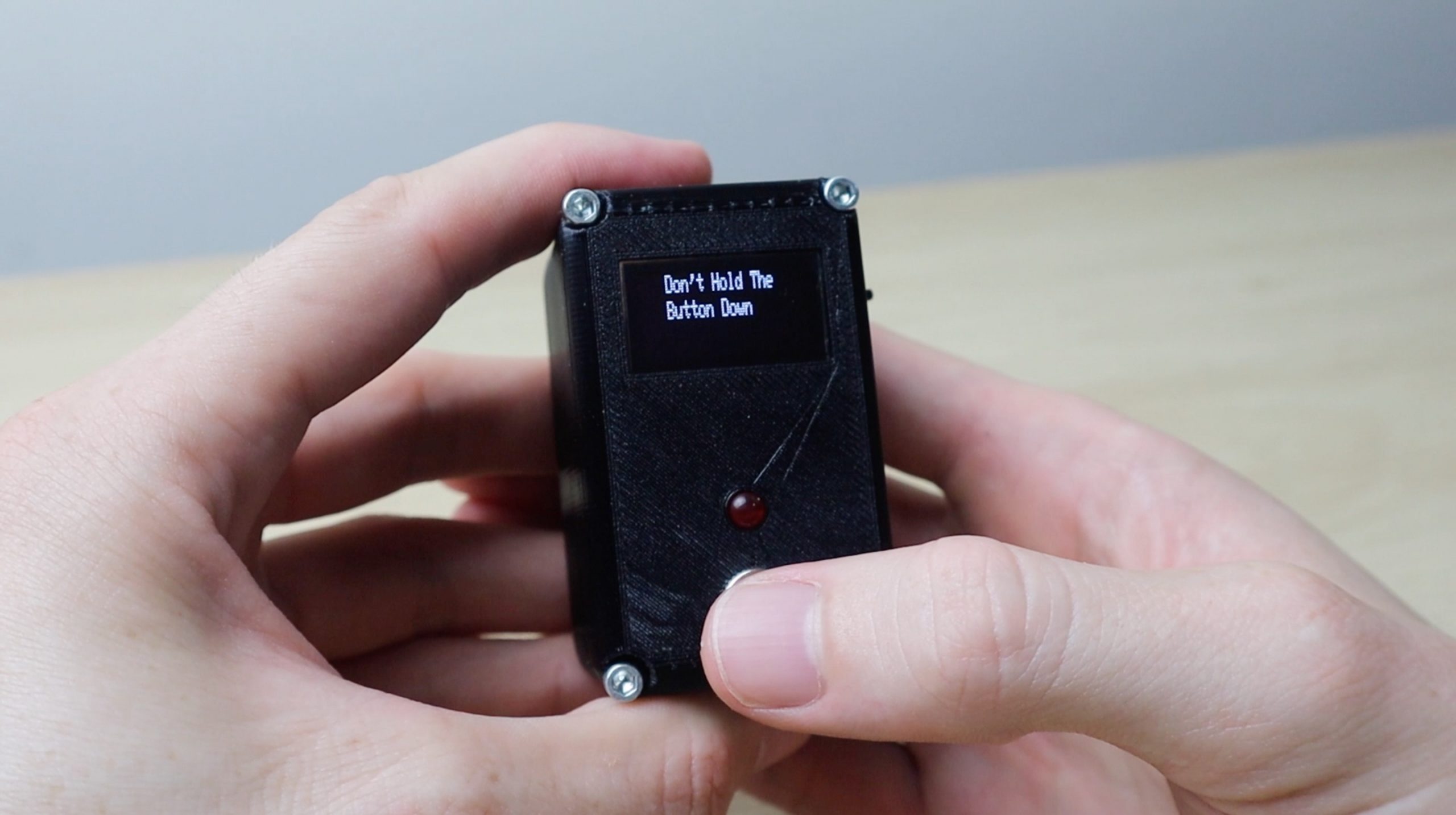
if (totalTime <= 20) //Check for cheating by holding the button down
{
display.setCursor(20,0);
display.println(F("Don't Hold The"));
display.setCursor(20,10);
display.print(F("Button Down"));
}
else //Display the results
{
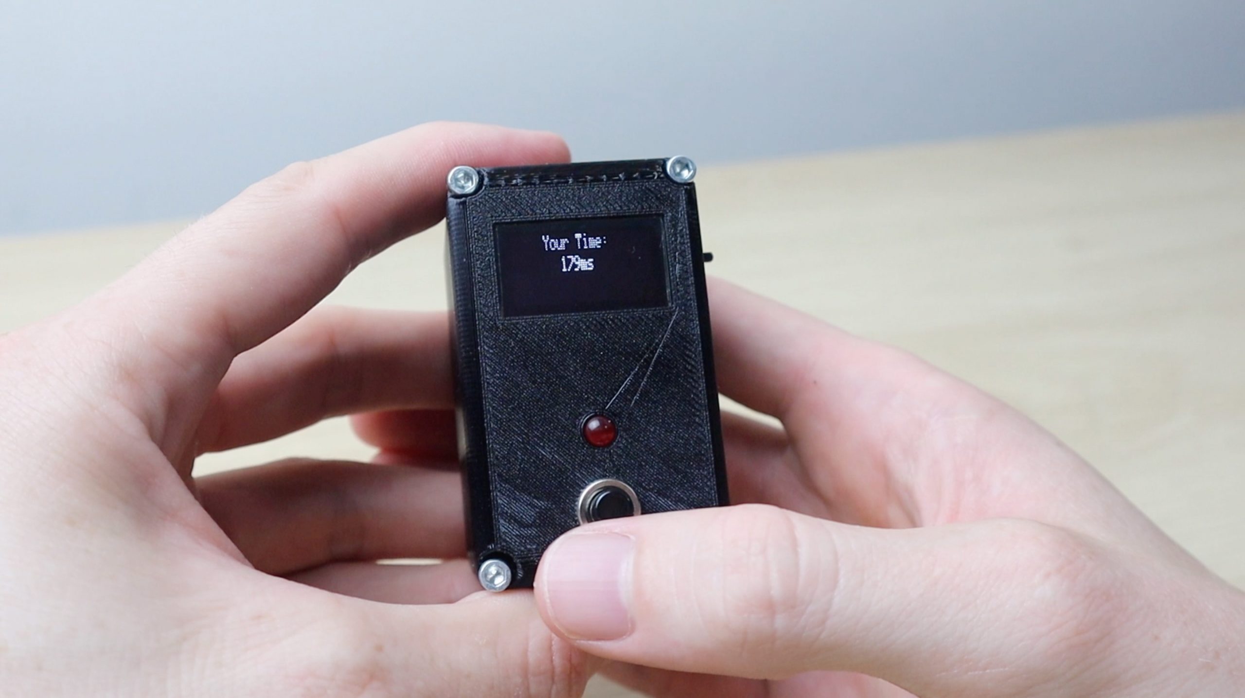
display.setCursor(30,0);
display.println(F("Your Time:"));
display.setCursor(45,10);
display.print(totalTime);
display.print(F("ms"));
}
display.display();
delay(5000); //Wait 5 seconds on results before restarting
}
delay(100);
}
Download the sketch – ReactionTimerSketch
We start by importing the libraries required for the OLED display, you’ll need to install the adafruit_SSD1306.h and adafruit_GFX.h libraries. These can also be installed directly from your library manager in the Arduino IDE.
We then define the display’s width and height in pixels and create the display object. Then define the pins for the push button and LED and create variables to record the start and end time to measure the reaction duration.
In the setup function we define the pin modes for the LED and button and then start the display. If there’s a problem with communicating with the display, the program won’t continue into the loop function.
In the loop function we clear the display, then set the font size and colour before displaying the text “Press to Play”.
If the button is pressed, we start the reaction timer routine. A countdown is started in the form of displaying “Ready” and three dots/periods in one second increments. After the last dot is displayed, we generate a random delay between 2 seconds and 7 seconds. This is to eliminate the possibility of the user learning the timing in the routine and trying to time their press to guess at when the LED is going to light up.
We wait this period of time, turn the LED on, record the start time and wait for the user to push the button. Once the button is pushed we record the end time, turn the LED off and then calculate the total reaction time.
I’ve included a section to disregard the input if the response time was less than 20 milliseconds. After doing a bit of research online, it seems like most people’s response time is about 200 milliseconds, with professional athletes and gamers able to reduce this to around 120 milliseconds. In fact the IAAF defines a false start as an athlete responding to the gun in under 100 milliseconds. So 20 is well under this threshold and is mainly in place to make sure that the button is initially released and not just held down the whole time.
If the reaction time was considered to be valid, then it is displayed on the screen for 5 seconds before the code returns to the initial screen.
Now upload the code and try it out.
Assemble The Components Into The Housing
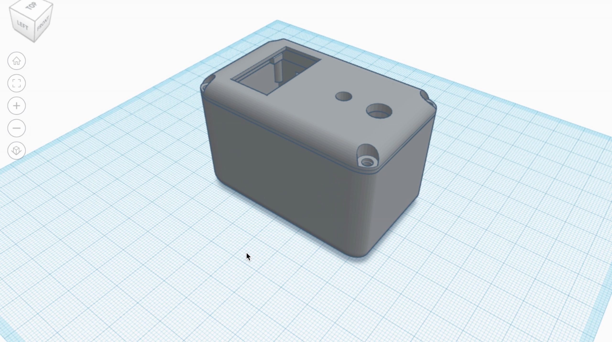
I measured up the components and designed a small 3D printable housing for them.

The housing has cutouts for the display, LED and push button on the top and a slot for the power switch on the side. To replace the batteries, you’ll need to remove the front cover, but you shouldn’t have to do this very often.
Download the Reaction Timer 3D print files – 3D Print Files
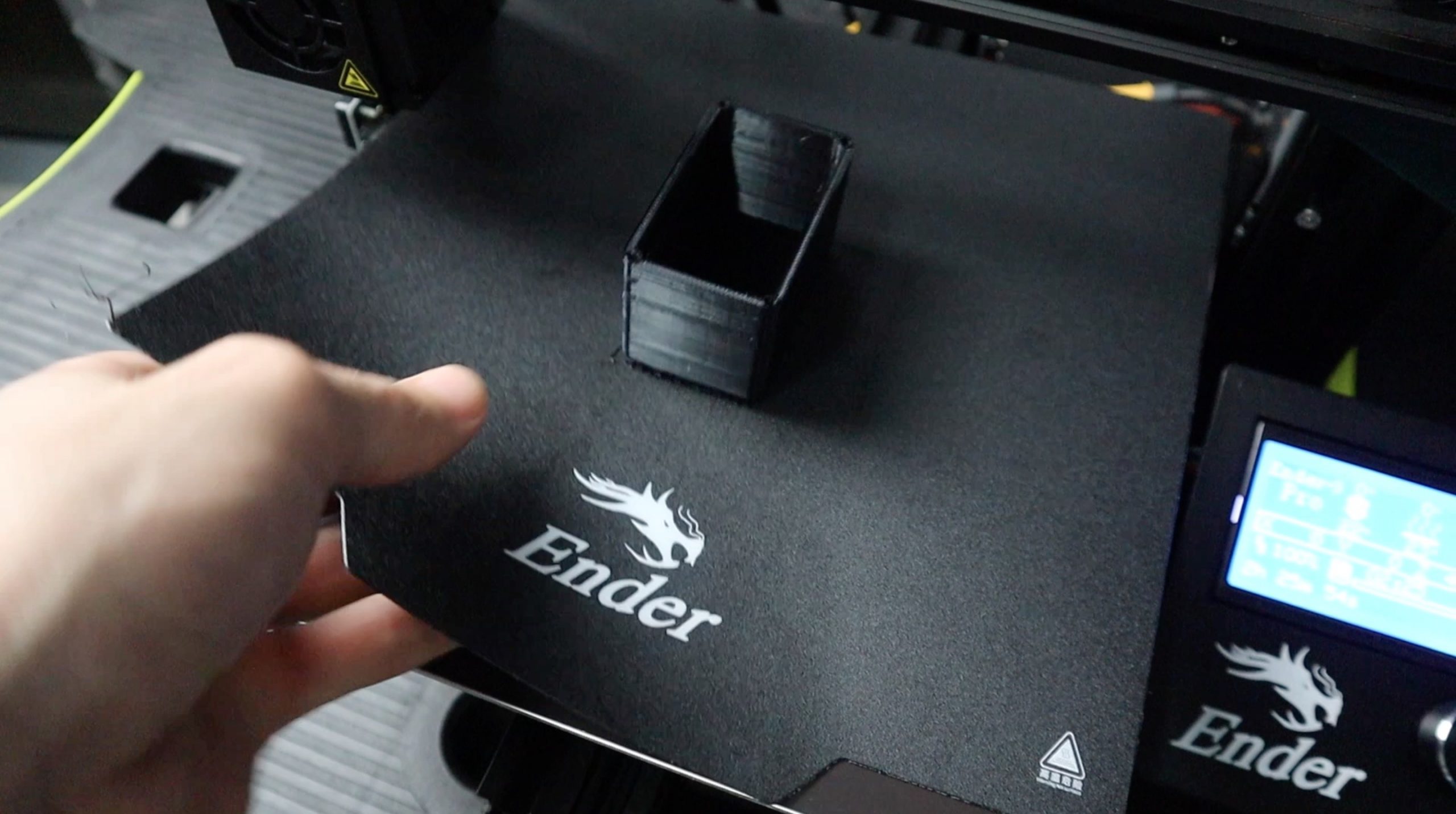
I printed the components using black PLA at 210°C with a 15% infill. The wall thickness is set to 1.2mm and the print speed was 25mm/s.
The OLED display is held in place with clips along the top edge and using the plastic clamp and an M3 x 6mm screw on the bottom edge.
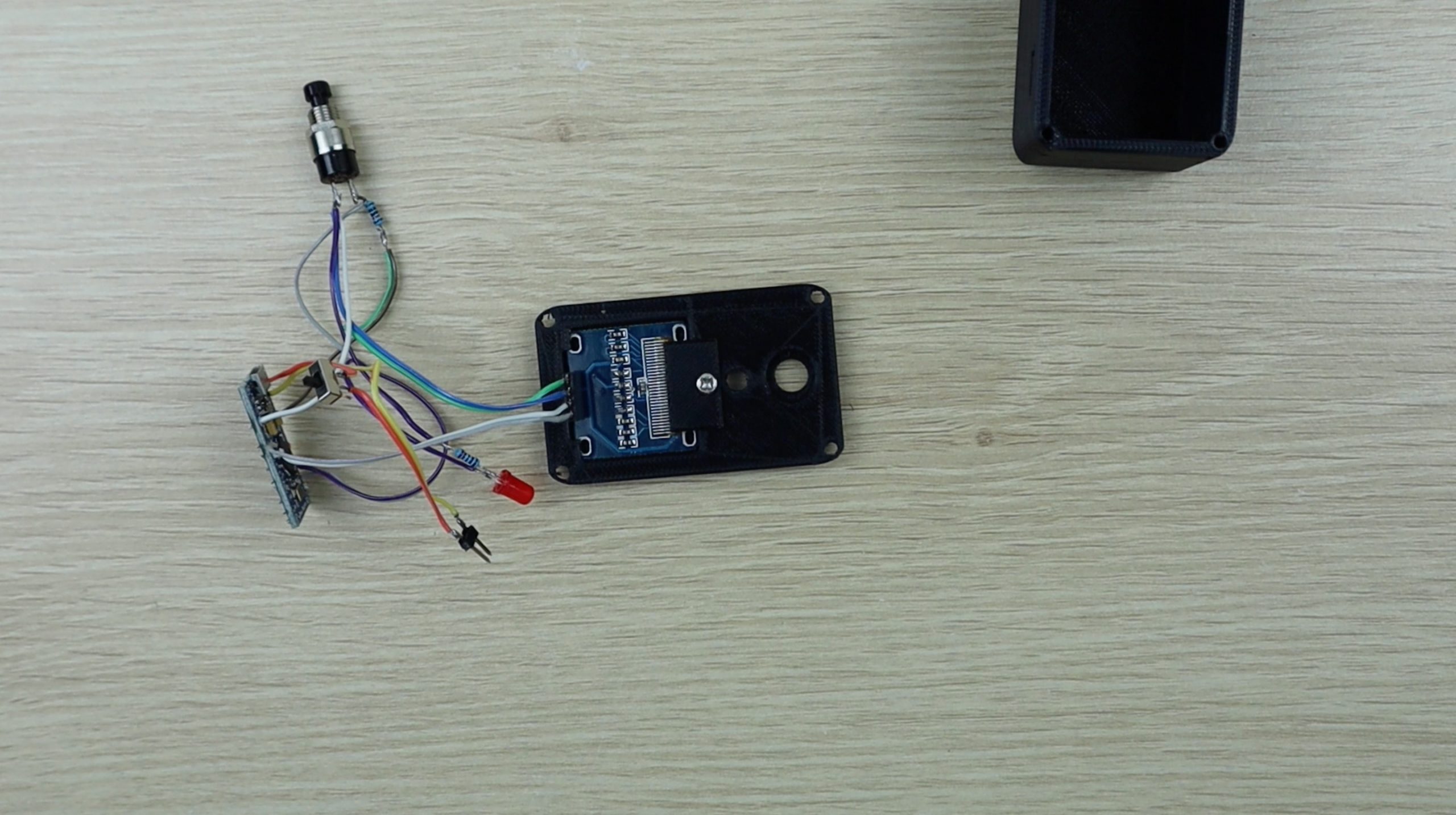
The LED just presses into place and the push button is held in place using the ring nut which is supplied with it.
Push the power switch through the side of the housing, it can be held in place with a drop of super glue if it is loose. Next, slide the battery holder into the bottom of the housing and then connect the power cable, making sure that you get the polarity correct.
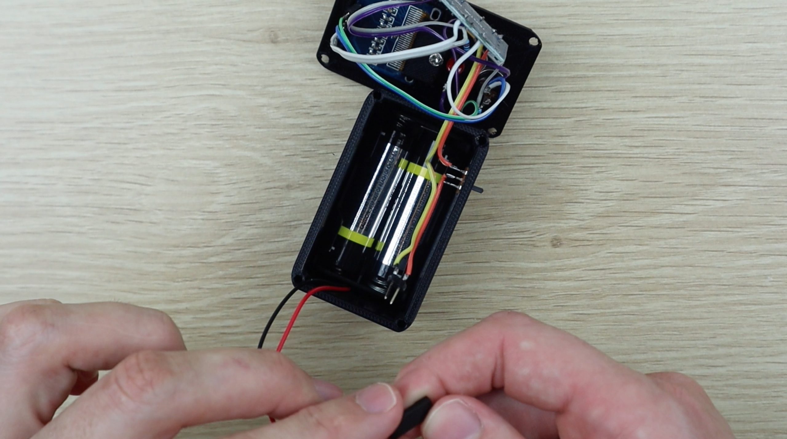
It’s also a good idea to use heat shrink tubing around your exposed connections or cover them up with a bit of insulation tape. You don’t want any terminals or leads shorting out once you’ve placed the into the housing together.
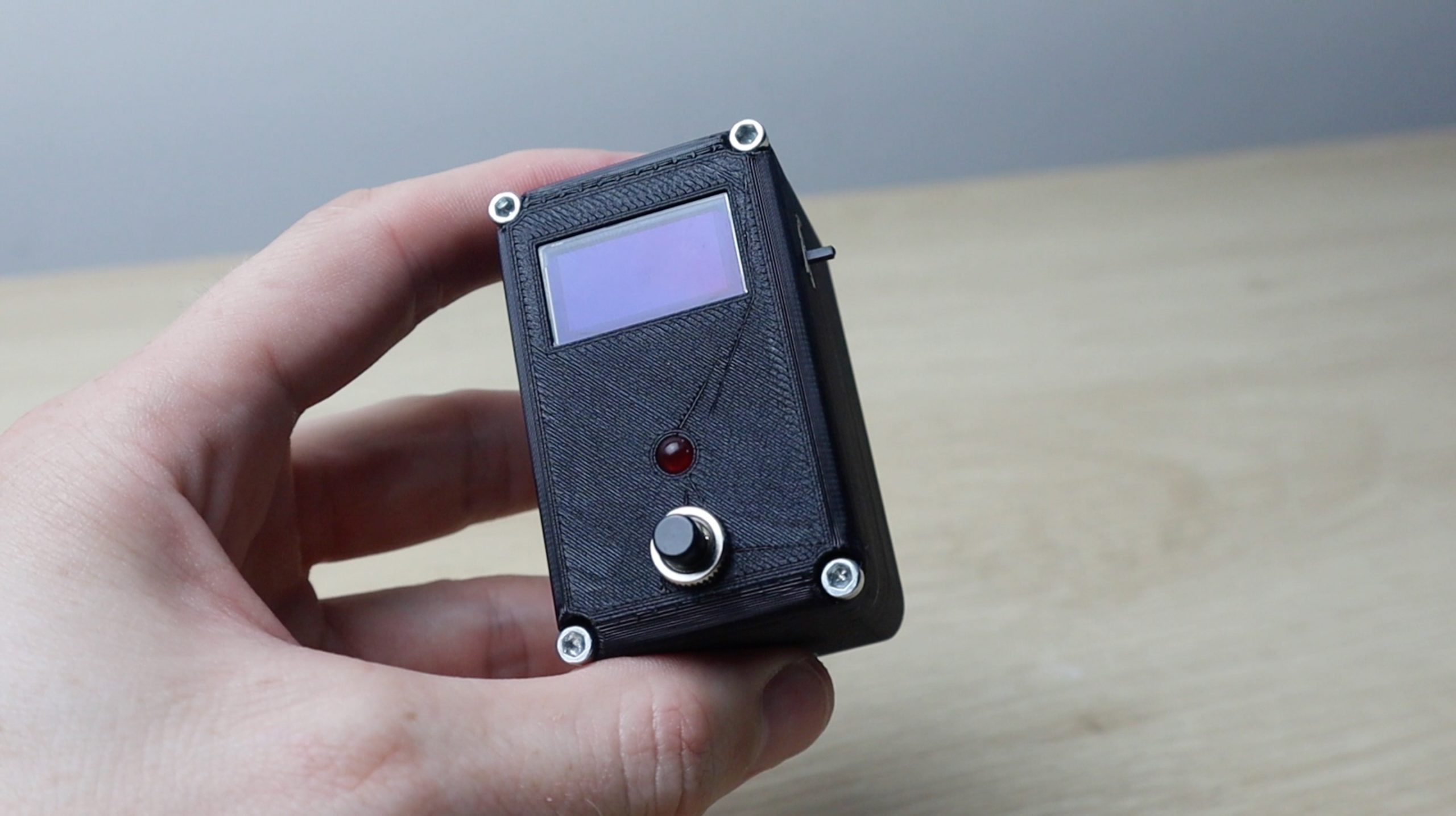
Attach the front cover and secure it with 4 – M3 x 12mm cap screws. I’ve used 12mm screws so that I didn’t have to use threaded brass inserts in the housing. The 12mm length on the screws is enough to get a good grip on the housing without pulling through the plastic, just don’t over tighten them.
Using Your Arduino Based Reaction Timer
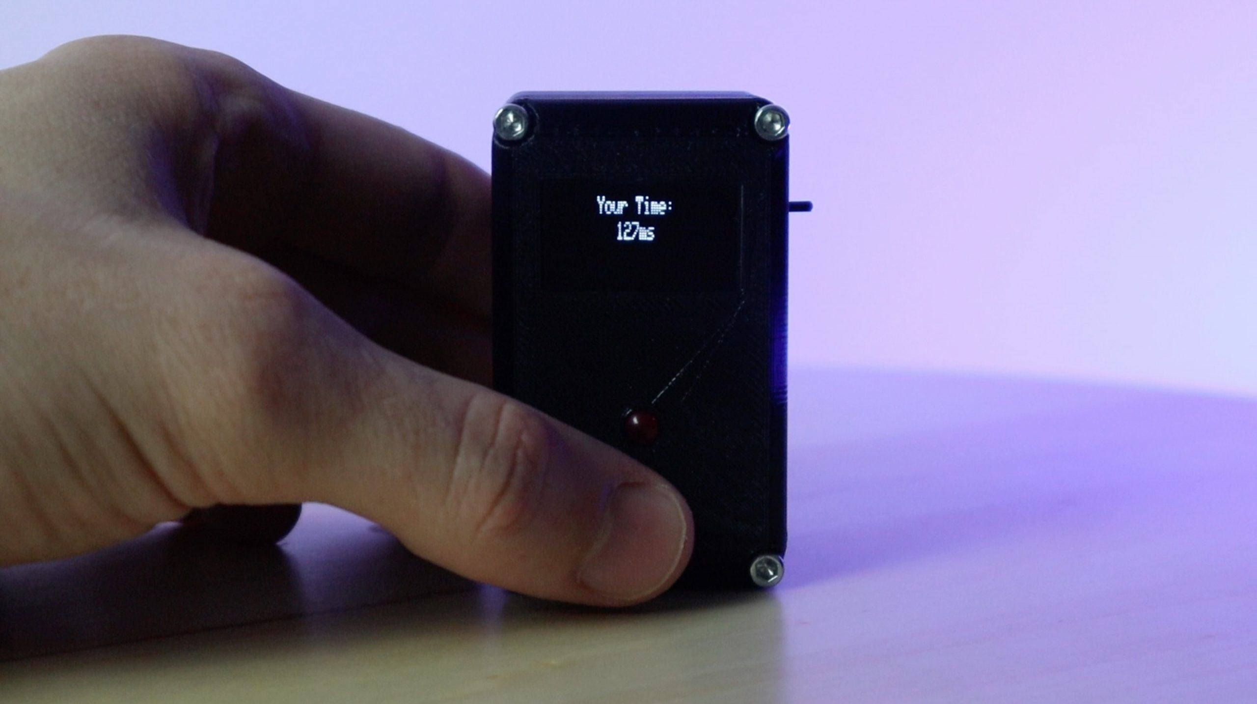
Once the screws are secure, slide the switch on the side to turn on your reaction timer and try it out. Press the button once to start the game and then wait for the red LED to light up.
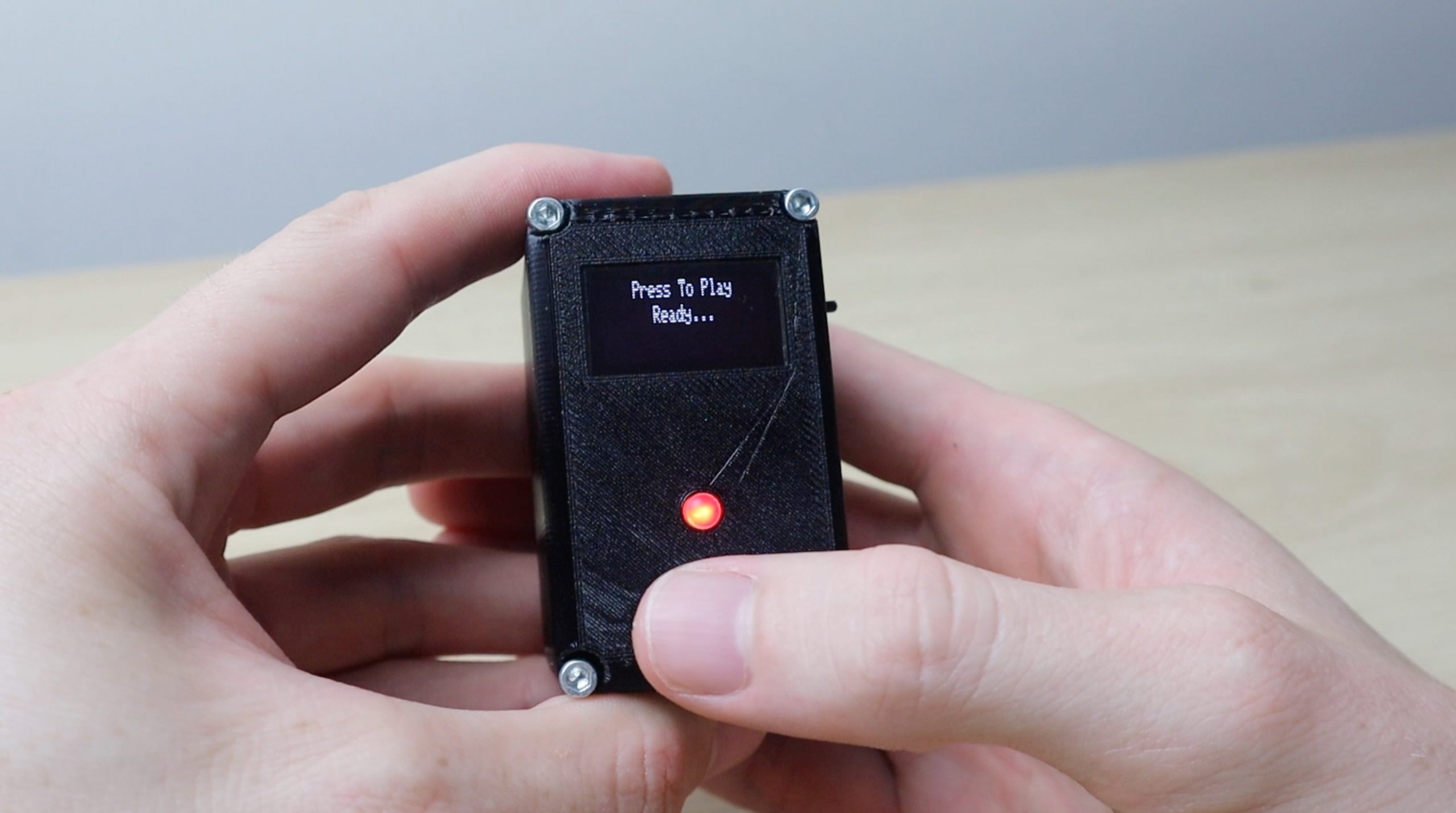
Once the LED lights up, push the button again as quickly as possible. Your reaction time will then be calculated and displayed on the screen. Typical reaction times are between 200 and 250 milliseconds, you’re doing well if you can get under 200. Some professional athletes and gamers are able to get as low as 120 milliseconds.
Don’t just press and hold the button. The game detects this and will discard your results.
Have fun improving your reaction time by trying to beat your personal best and challenging your family and friends. Let me know what your best reaction time is in the comments section.
Share This Project
Hi Michael,
first of all a great little project and description of the build.
is there a way to keep the lowest recorded time on the screen until it is switched off,
New to Arduino programming but learning fast.
best regards
Laurence
Hello,
Fairly new to Arduino and coding. This is really cool but having an issue.
Getting this error when compiling,
“text section exceeds available space in board
Compilation error: text section exceeds available space in board”
There is a “F macro” commend tip for helping with this issue, but the “F macro is already used in your code.
Don’t know how to fix this. Can you help?