Last year, I built a Pi-based NAS as cheaply as possible using a Raspberry Pi Zero 2W. It was a great project to learn what a NAS is and how to set one up, but it was obviously limited by the capability of the Zero 2W and the cheap storage hardware that was used. So, today we’ll be building a more functional and powerful NAS using a Raspberry Pi 5.
Here’s my video of the build, read on for the write-up;
What You Need To Build Your Own 4-Bay NAS
- Raspberry Pi 5 – Buy Here
- Raspberry Pi 5 Active Cooler – Buy Here
- Radxa Penta SATA Hat (Pi 5 Kit) – Buy Here
- Sandisk 32GB MicroSD Card – Buy Here
- 12V 3A Power Supply – Buy Here
- 4 x Crucial 2.5″ BX500 SSDs – Buy Here
- Noctua 40mm 5V Fan – Buy Here
- M2.5 Button Head Screws – Buy Here
- M2.5 Brass Inserts – Buy Here
- M3 Button Head Screws – Buy Here
- Wavelink 2.5G Ethernet Adaptor (Optional) – Buy Here
Equipment Used
- Bambulabs X1C 3D Printer – Buy Here
- USB-C Pencil Screwdriver – Buy Here
- TS100 Soldering Iron – Buy Here
- Brass Insert Tips – Buy Here
- Gweike Cloud Laser – Buy Here
- Acrylic Bending Tool – Buy Here
Some of the above parts are affiliate links. By purchasing products through the above links, you’ll be supporting this channel, at no additional cost to you.
Hardware Used To Build The NAS
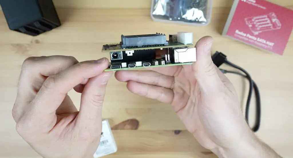
The primary piece of hardware that we’ll be using to build the NAS, apart from the Pi 5, is this new Penta SATA hat from Radxa. This hat allows up to 5 SATA drives to be connected to a Raspberry Pi 5 or Rock 5A via their PCEe port.
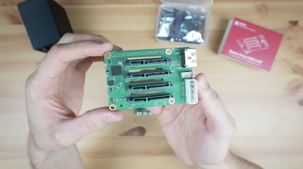
It’s got 4 SATA ports on the top, which drives plug into top-down, and one eSATA port on the front. Radxa include a cable to plug a fifth drive into this port with the hat. The spacing between the SATA ports allows for 2.5″ drives to be plugged directly into it, but you can also connect 3.5″ drives to it with some extension cables.
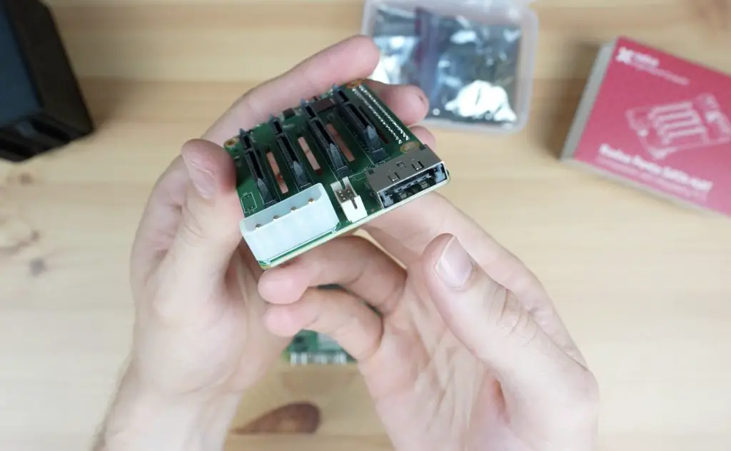
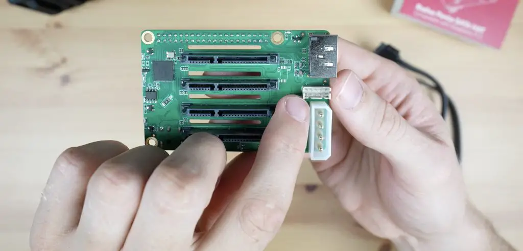
Power is supplied to the hat through either a 12V barrel jack on the side or a standard ATX Molex connector on the top. Additionally, you don’t need a second power supply for your Raspberry Pi 5 – the hat will supply 5V to the Pi through the GPIO pins. That’s a really handy feature!
The Penta SATA Hat has got a couple of other ports on it too, like an expansion port for a fan and OLED display on top and an additional fan port at the bottom.
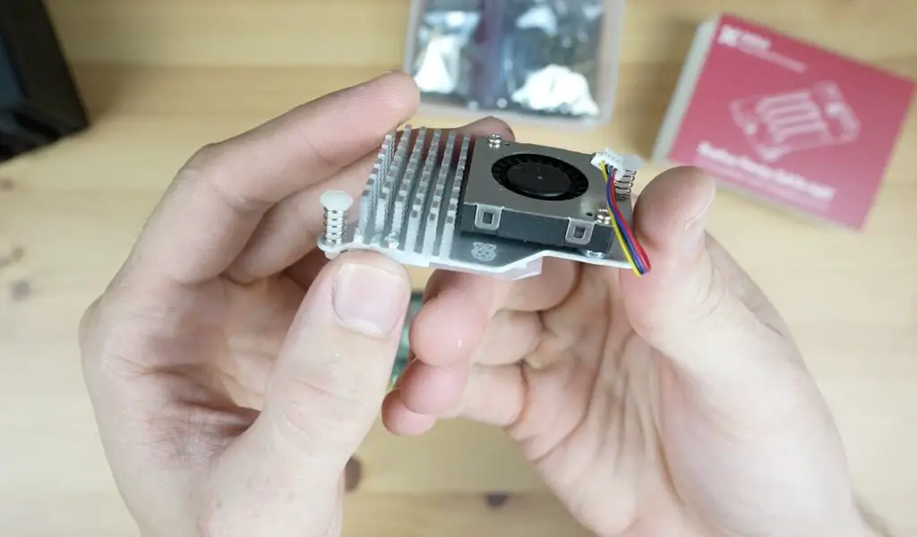
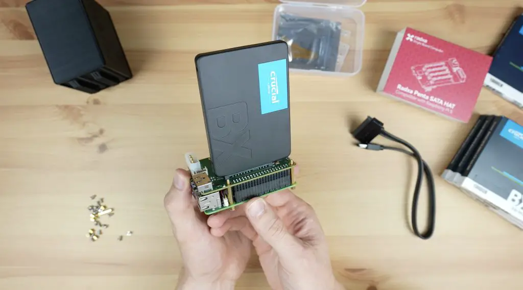
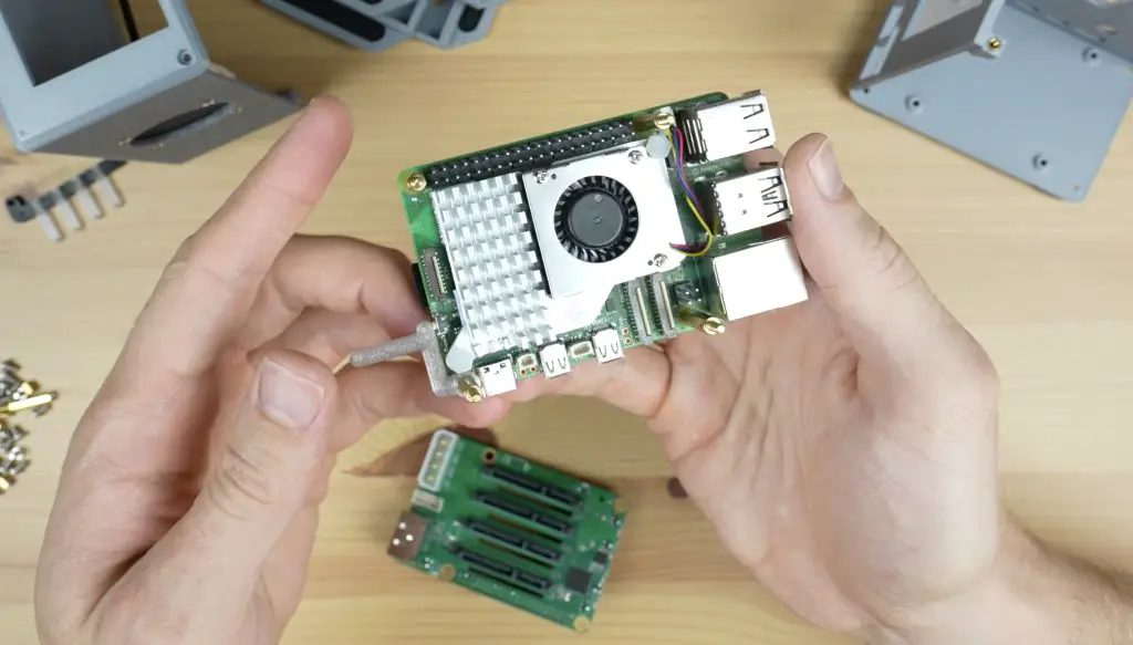
Before mounting the hat onto the Pi 5, we need to add a cooling solution for the Pi’s CPU. I’m going to use a Pi 5 active cooler.
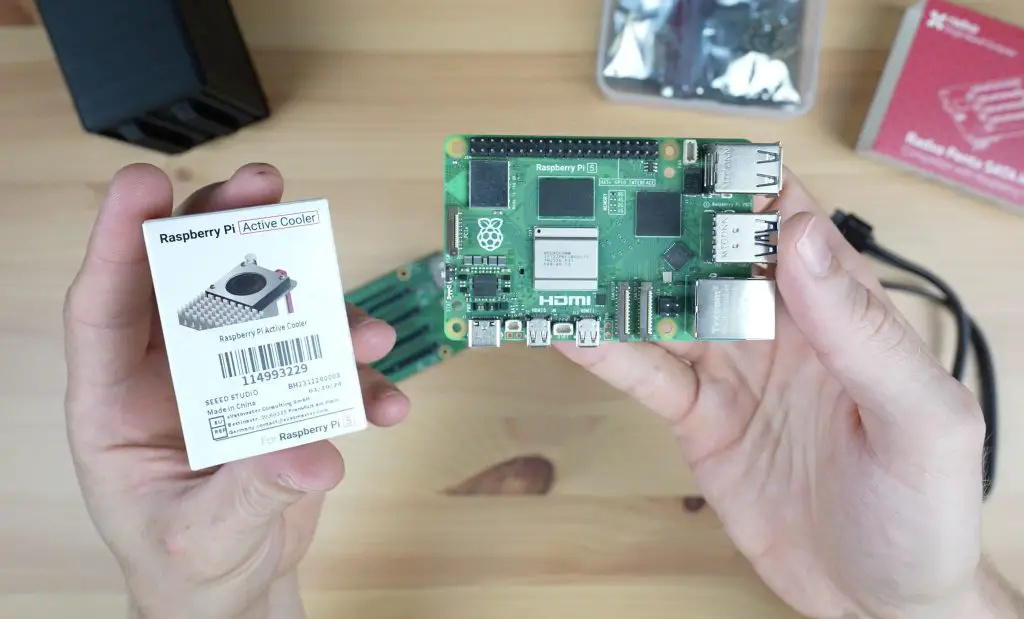
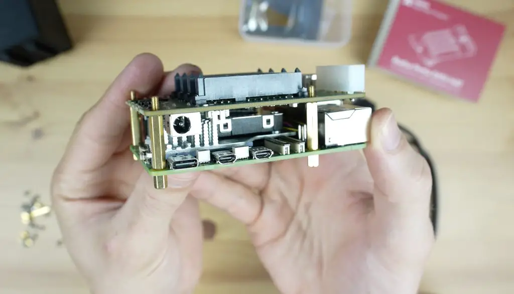
There is one issue with using this cooler and that’s that the end three fins on the heatsink clash with the barrel jack port on the hat. This seems like a bit of an oversight by Radxa but hopefully, they’ll come up with a solution to correct this in future revisions.
My first thought was to add some 6mm spacers between the hat and Pi so that there is a larger air gap between them. This however isn’t possible without also requiring an adaptor for the GPIO pins to still plug into the hat.
The only easy solutions are to either get rid of the cooler or modify the cooler to fit in underneath the connector. Modifying the cooler can be done relatively easily by removing the last three fins, which you can break off with needle nose pliers.
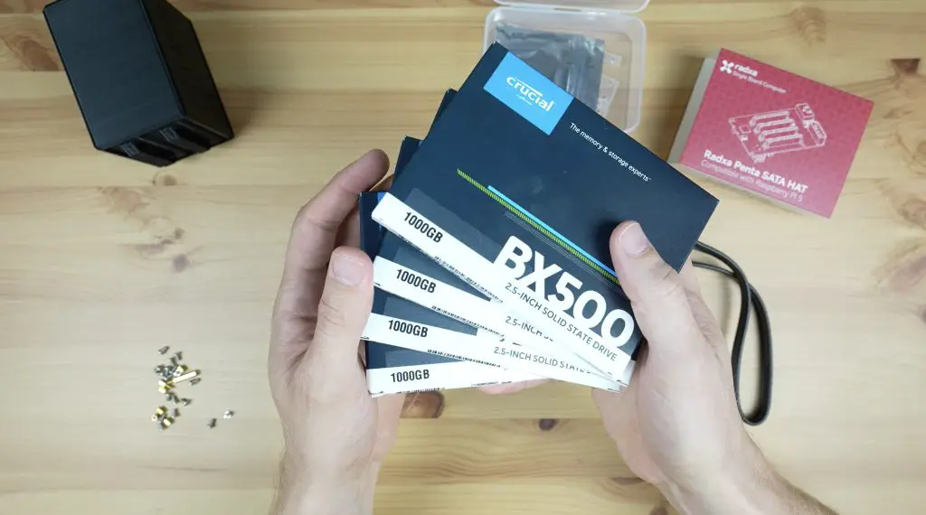
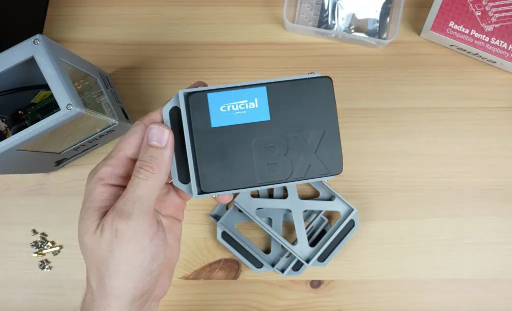
For storage, we’ll use some Crucial BX500 drives as I think these strike a reasonable balance between cost and quality. We’re going to be bottlenecked by the single PCIe lane shared between the drives so there isn’t much point in getting the fastest drives available, any reasonably good quality 2.5″ SSDs would work for the build.
Lastly, we need a microSD card for the operating system. We’ll use a 32GB Sandisk Ultra card for this. I’ve been using these for my Pi projects for years and have had very few issues with them.
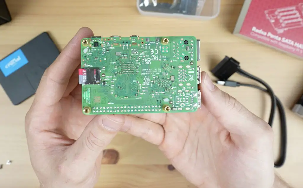
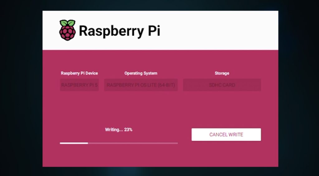
I flashed the microSD card with Raspberry Pi OS Lite using Raspberry Pi Imager. This is the base operating system onto which we’ll be installing the NAS software Open Media Vault or OMV. When flashing the operating system image, you may want to change the name of your NAS and you’ll need to enable SSH so that you can log into the Pi remotely once it has booted up to install OMV onto it.
Radxa include hardware with the hat to secure the drives to each other. These make the drive stack a bit more secure, but I’d like to build the stack into an enclosure to better protect the Pi and Penta SATA hat, and provide some cooling to the drives.
Designing The Enclosure
To design the enclosure, I used Fusion360. I started out with a model of the Rapsberry Pi 5, then added the Radxa SATA hat and drives and then modelled the enclosure around them.
My initial thought was to lay the stack down horizontally like a traditional 4-bay NAS, but the Ethernet port on the Pi, the power port on the side of the hat and the power button and activity LEDs on the opposite side mean that it would be oddly proportioned and difficult to get cables plugged into.
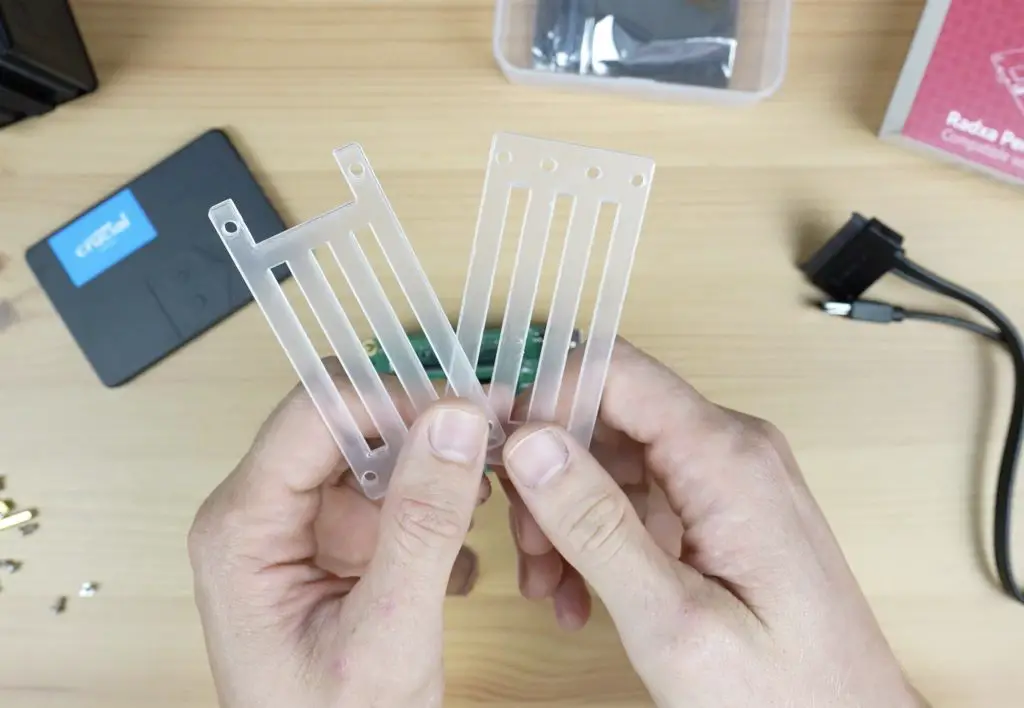
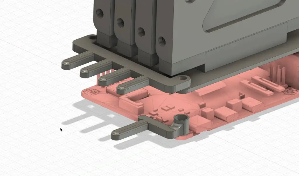
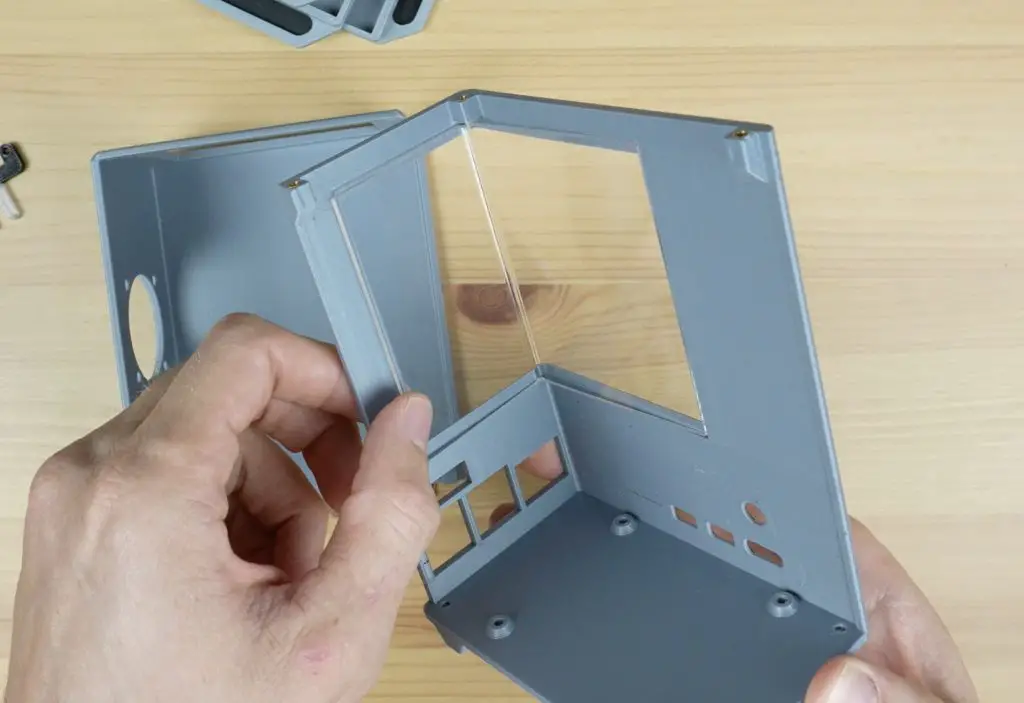
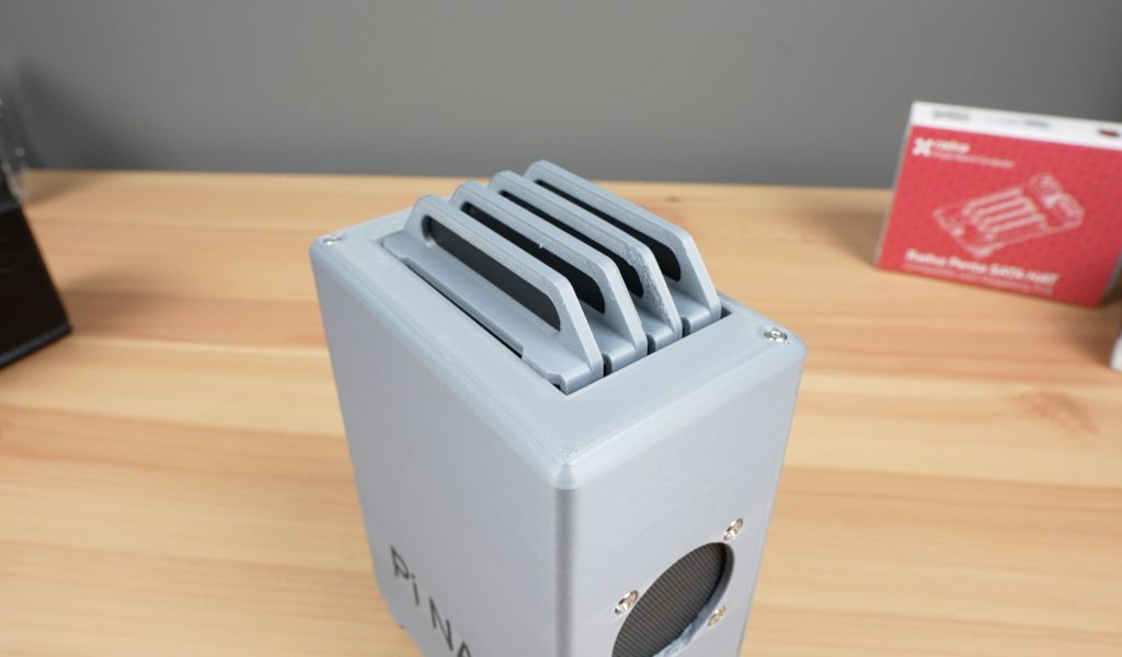
So, I decided to keep the vertical arrangement and rather have the drives plug in to the hat through the top. I designed a tray to hold each drive with a pull tab to make it easier to swap out individual drives if needed.
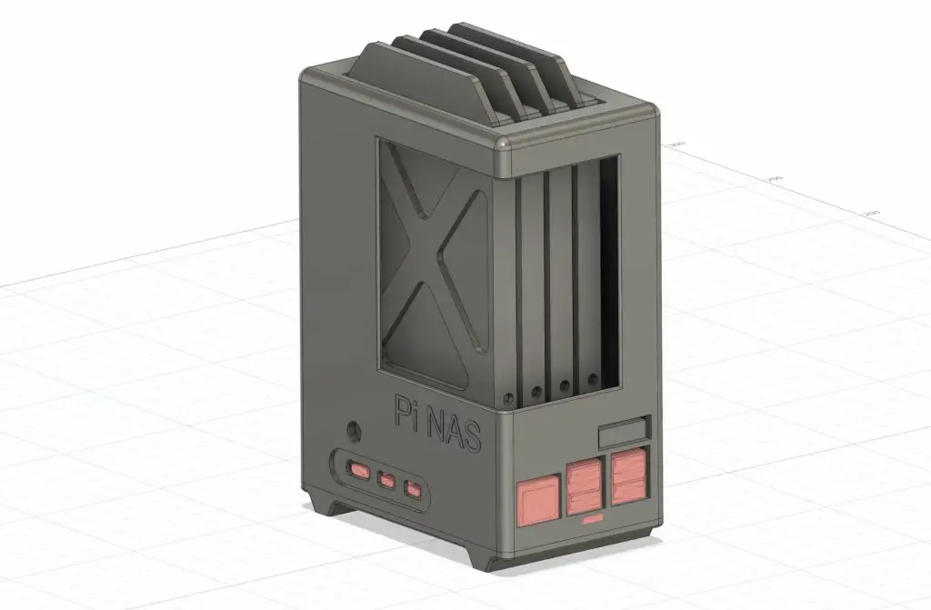
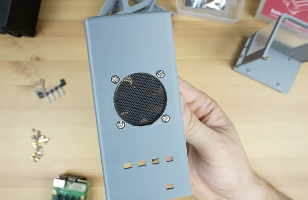
To cool the drives I’ve included a cutout for a 40mm 5V fan on the side which blows air across the four drives and the air then comes up and out the gaps between the drives at the top of the enclosure.
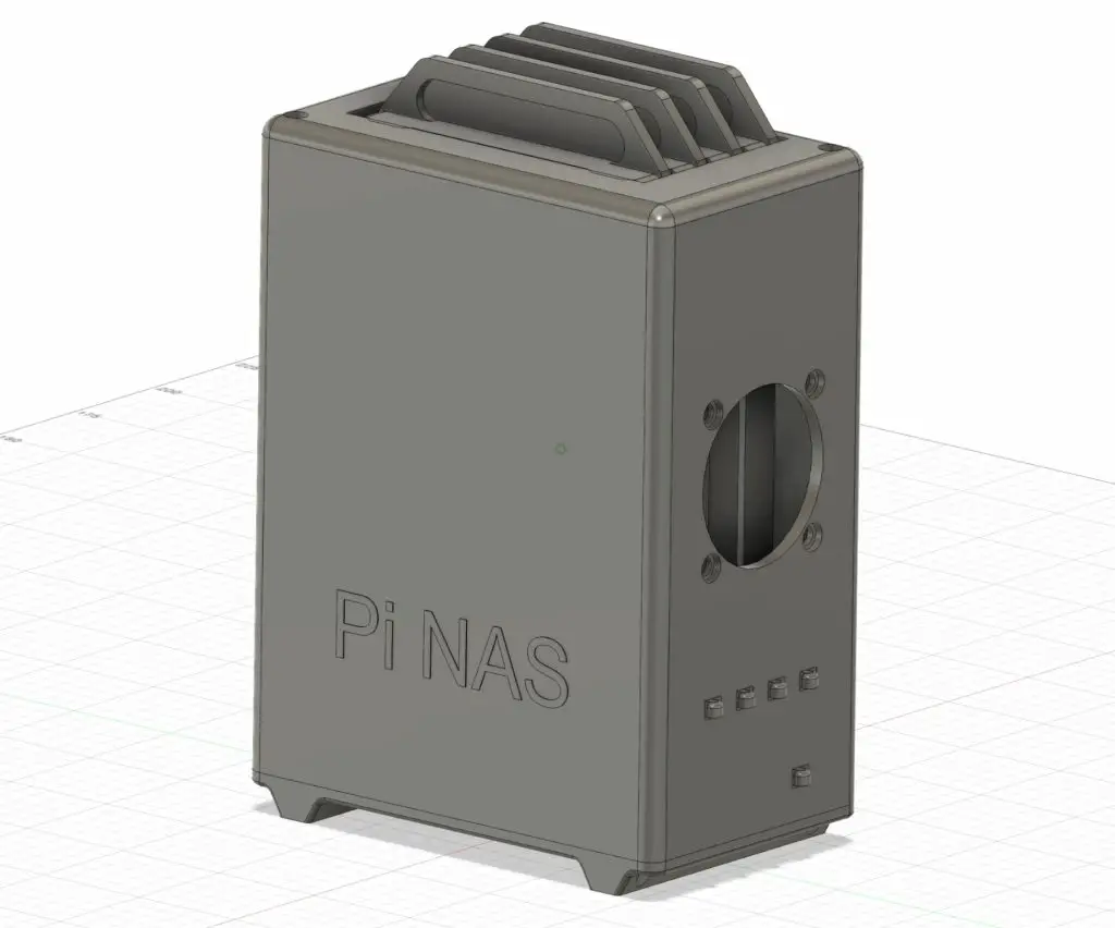
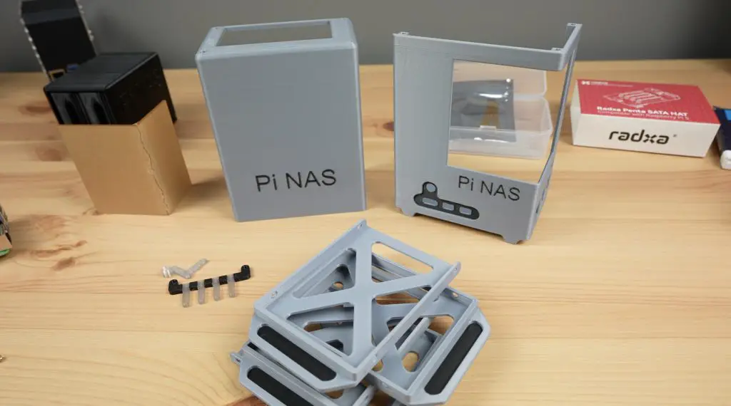
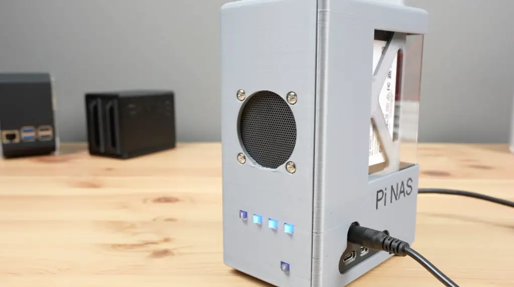
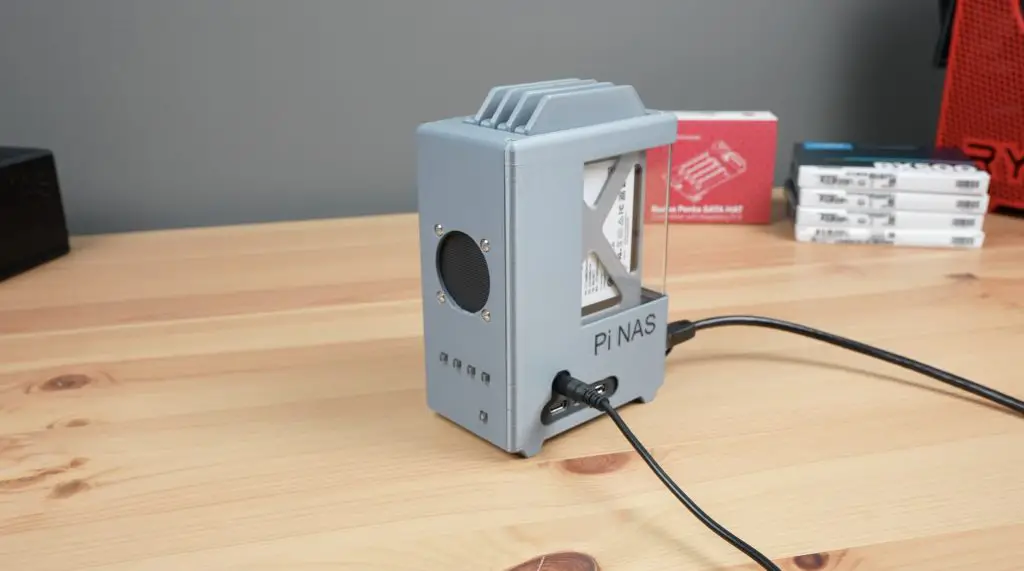
I also added an LED bar to bring the drive activity lights onto the side of the case as well as a button adaptor to allow the Pi’s power button to be pressed and its activity LED to be visible. I’ve included an optional window on the side of the NAS to look into the case to see the drives. I decided on including options with and without this window in the set of print files as I know most people don’t have the tooling required to make the window up but I think it makes the NAS look quite cool.
The enclosure is split into two halves which screw together around the stack, making it easy to pre-assemble and install.
With the design complete, let’s get the components printed out.
Making The NAS Enclosure
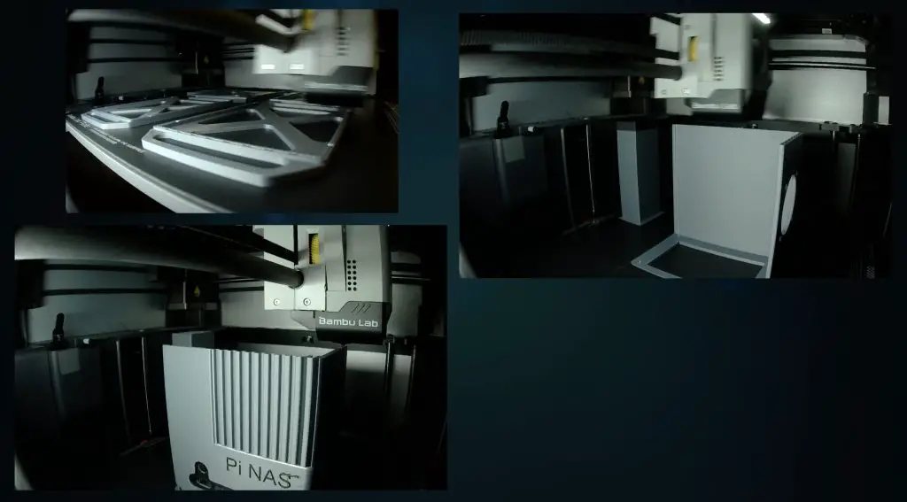
I imported the models into Bambu Slicer and set them up to print the main components out in aluminium-coloured PLA with black text. The button adaptor and LED bar are printed in translucent PLA with black sections between the LEDs to separate them. I also added a black accent to the pull tab on each tray.
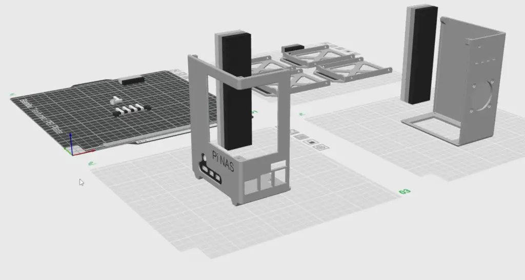
I then sent them to my 3d printer to print out across four build plates.
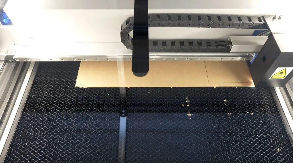
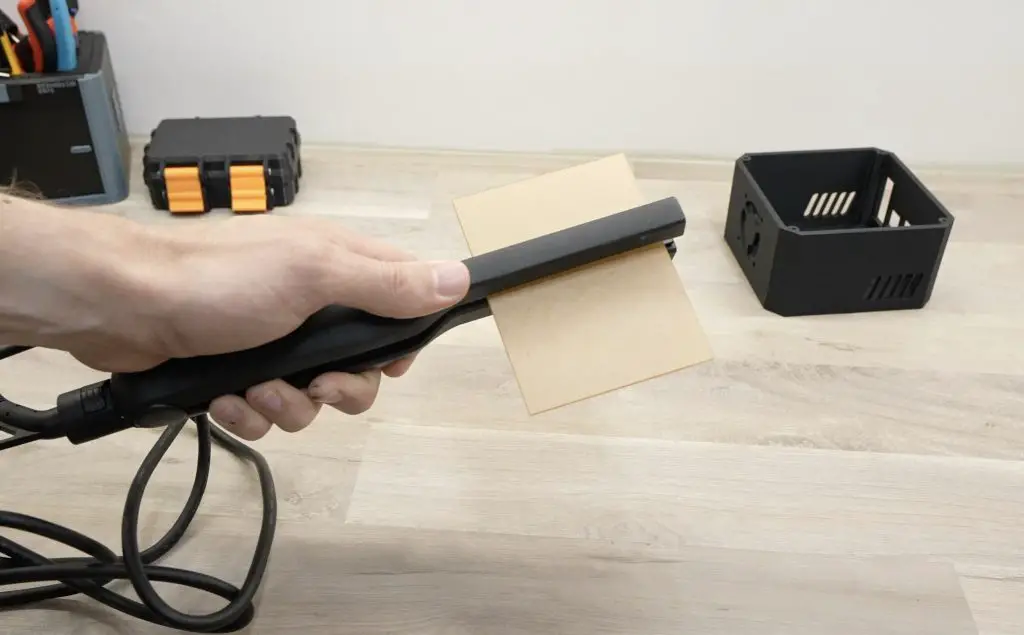
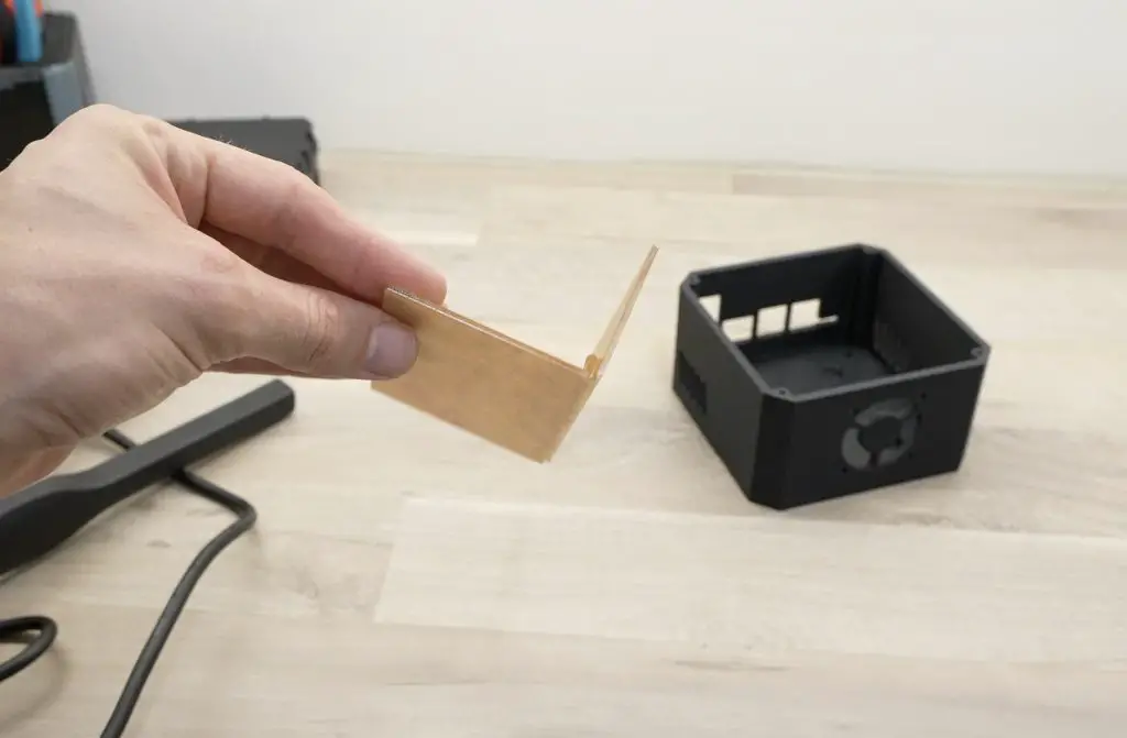
While the parts are being printed, let’s make up the side panel. This is laser cut from a piece of 2mm clear acrylic and we then use a bending tool to put the 90-degree bend into it.
The window is 108mm x 83mm and the bend line is placed 45mm from the edge. There are notches in the template below to guide placing the bend.
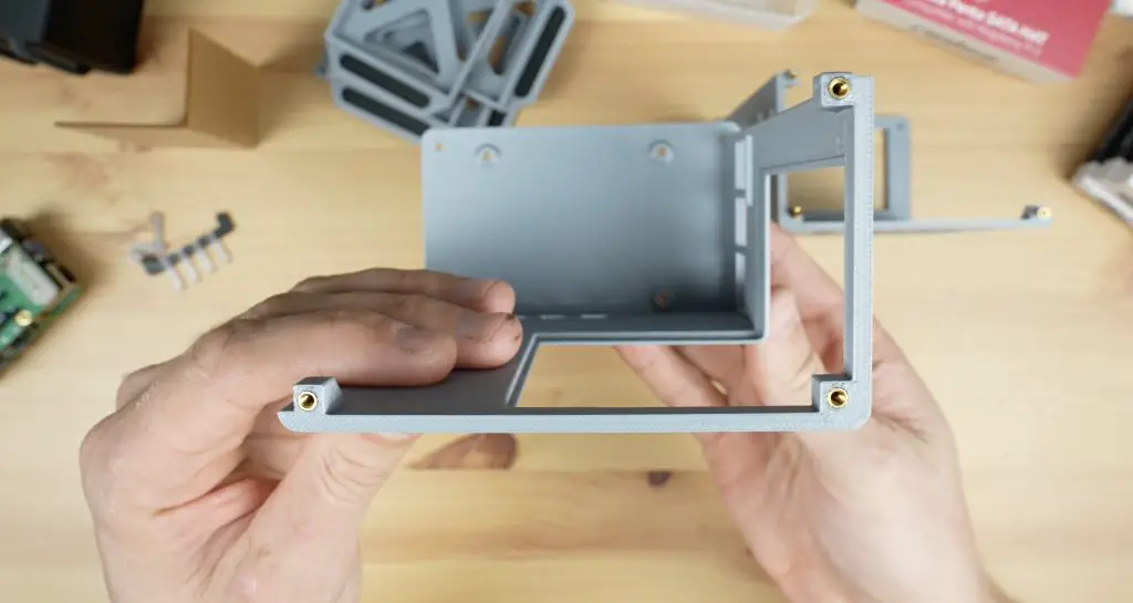
We now have all of the components required for the enclosure.
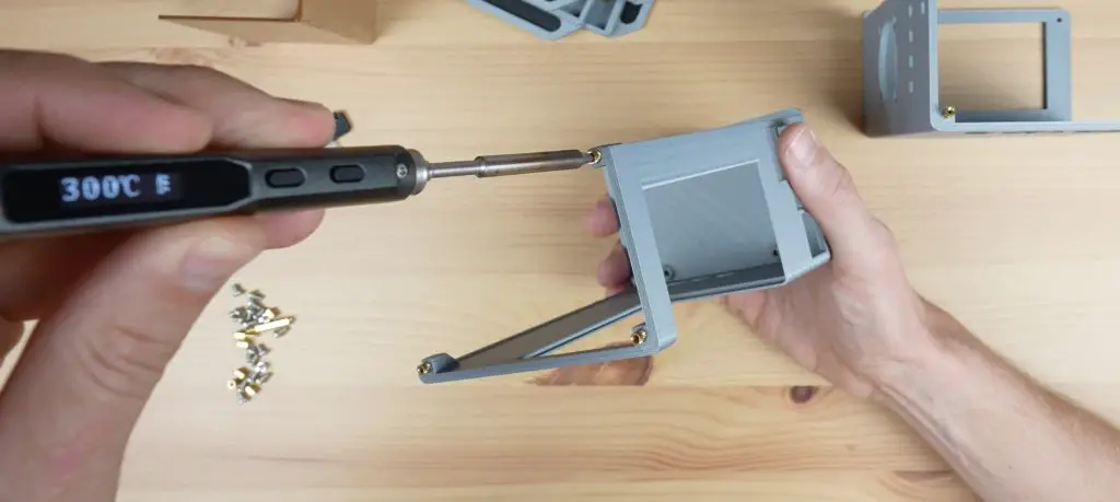
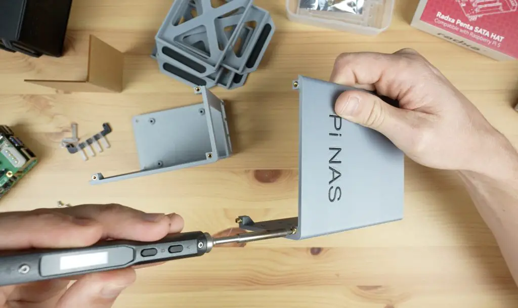
To finish off the 3D-printed parts, we need to add some M2.5 brass inserts for the screws to screw into. I’ve also included an option that doesn’t require these inserts in the print files to make it easier to make up but these inserts make the joints a lot more durable so I’d recommend using them if you plan on taking the enclosure apart more than a couple of times.
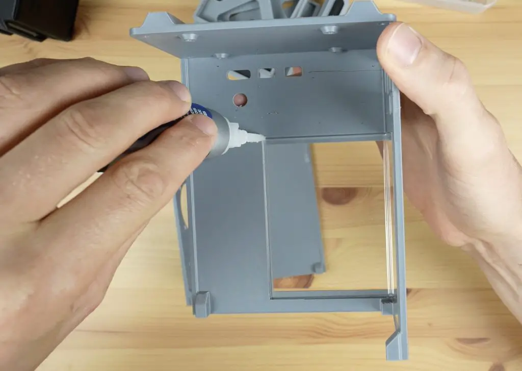
We also need to glue the window into place using a few drops of superglue or CA glue in the corners.
Mounting The Components Into The Enclosure
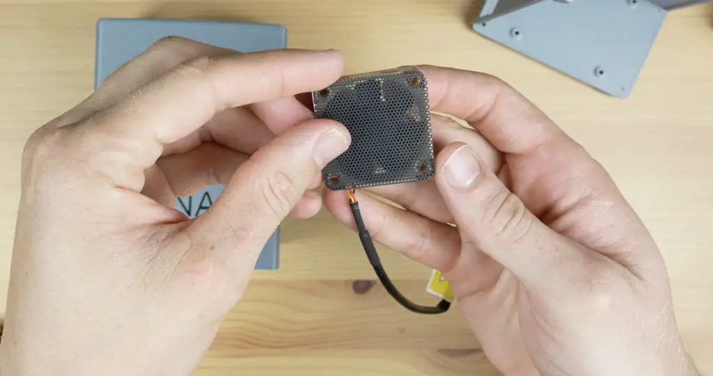
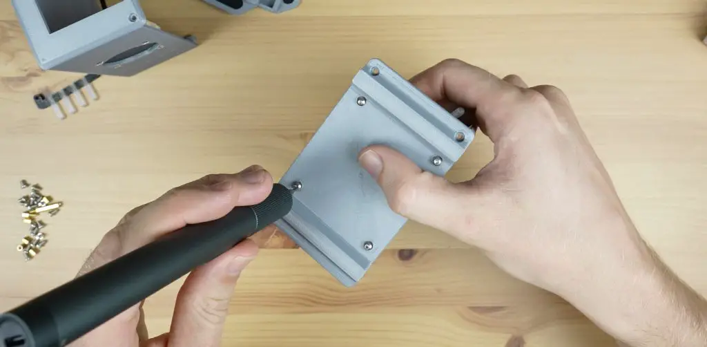
Now we can start mounting the components into the enclosure. Let’s start with the fan, which we can mount onto the side with some M3x12mm button head screws. I’m using a 40mm 5V Noctua fan with a thin dust filter between it and the case.
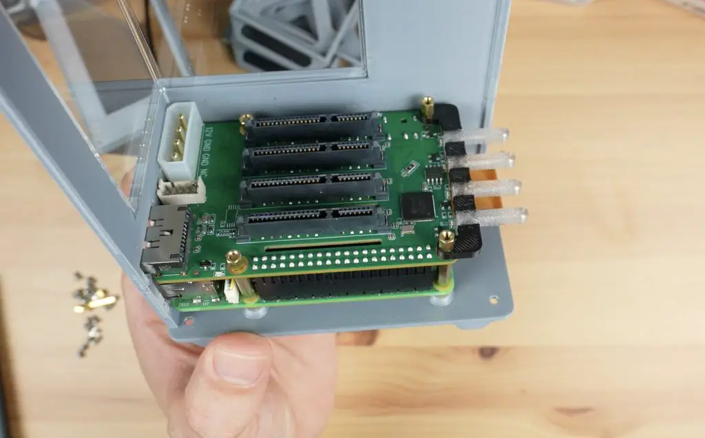
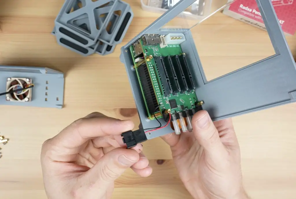
Before mounting the Pi assembly into the enclosure, we need to add the button adaptor to this corner standoff. It just pushes on around the standoff with a very light interference fit so that it is held in place securely but the button is still able to be pushed.
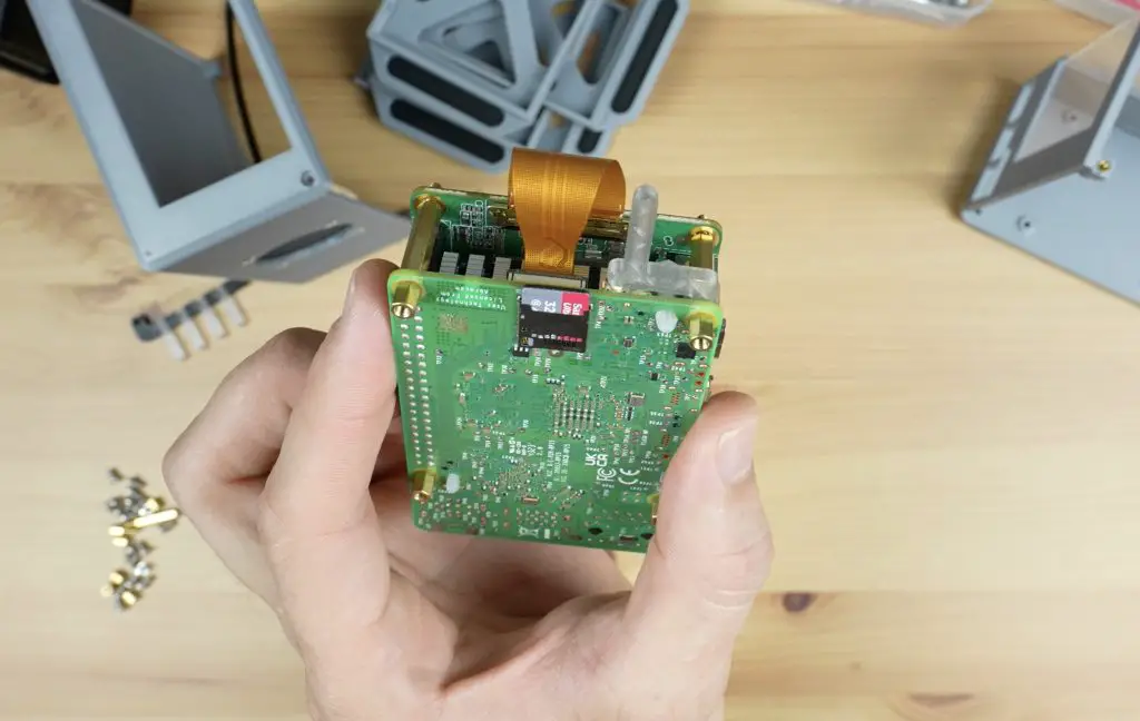
We also need to plug the FPC cable into the hat and the Pi.
We can then mount the stack to the bottom half of the enclosure using some M2.5x6mm screws through the base.
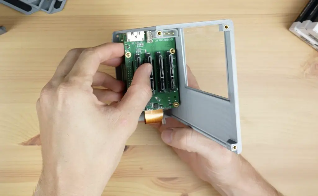
The status led bar is mounted to the back of the Radxa hat and is held in place with the Radxa hat’s standoffs.
I was going to power the fan using the port on the Pi or the Radxa hat but Noctua don’t have an adaptor to plug into these, so instead I soldered the included adaptor lead to the 3.3V and GND pins on top of the hat. The fan can then plug into this adaptor for power. I chose 3.3V so that the fan runs a bit quieter since it is not a PWM-controlled fan and will be running continuously.
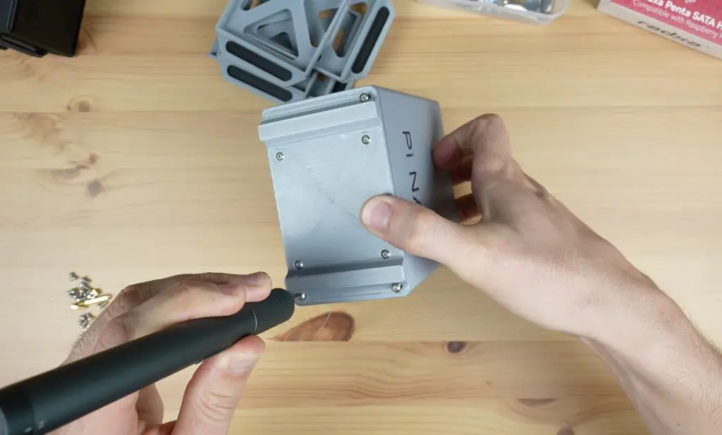
The top half of the enclosure then screws onto the bottom half using six M2.5x6mm screws, three on each end.
We’re now ready to plug our drives in and get our NAS booted up. Each drive is mounted into a tray using four drive screws provided with the Radxa Hat.
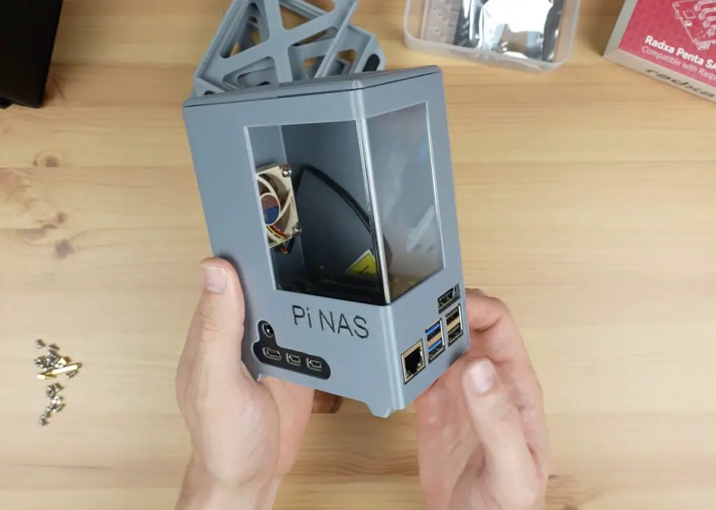
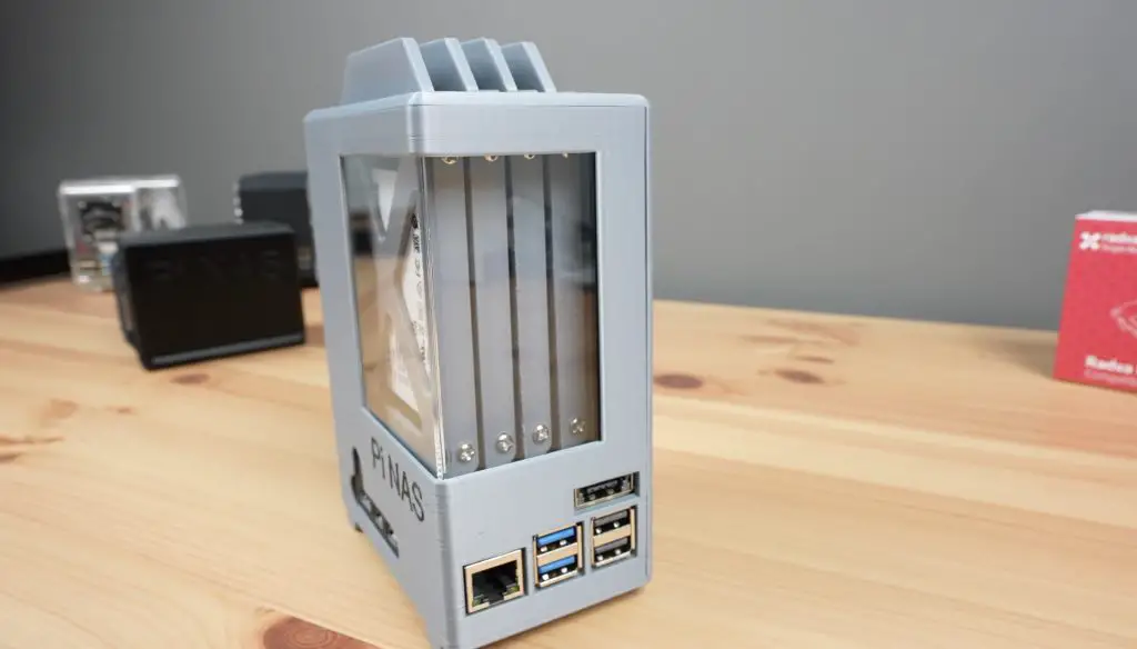
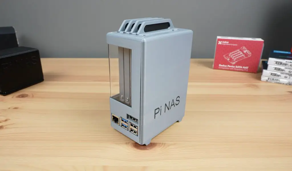
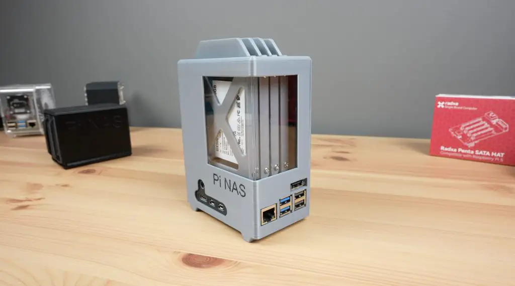
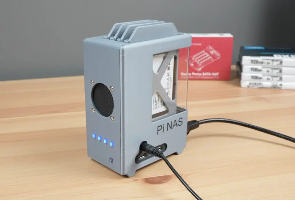
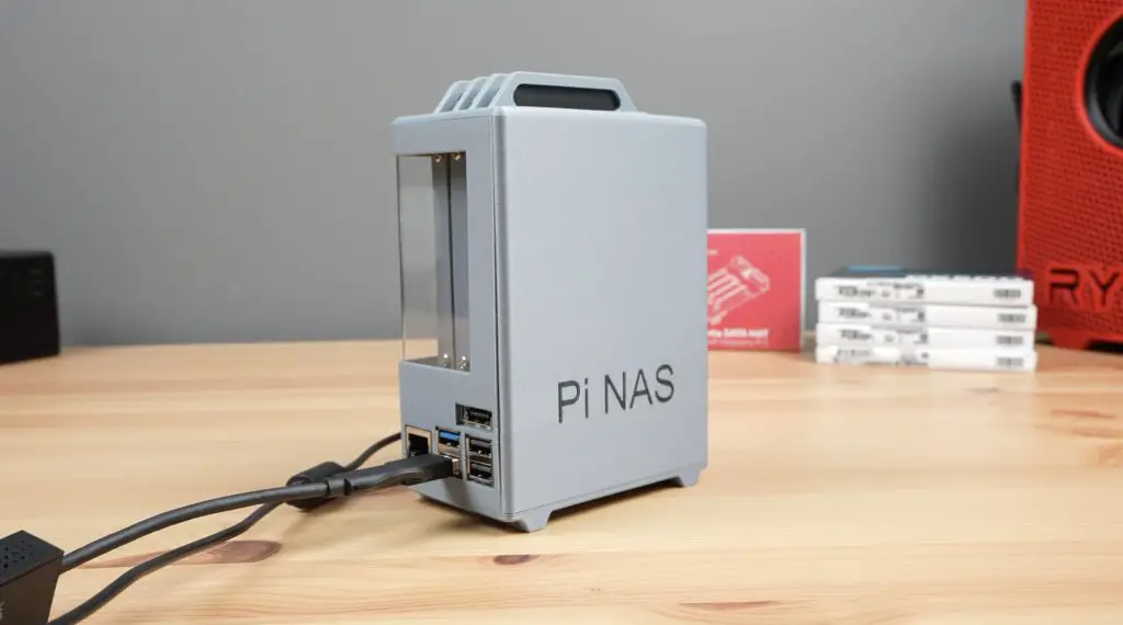
Completed Pi 5 NAS Enclosure
With that, our Pi 5 NAS is complete and ready for its first boot and setup.
First Boot & Software Setup
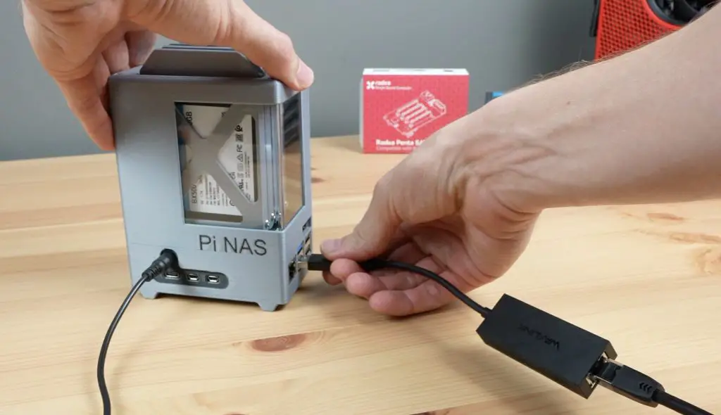
We only need power and a network connection to set up our NAS as we’ll be running it headless – meaning we’ll set it up through another computer. So let’s plug the 12V power supply and Ethernet cable into the NAS and it’ll be ready to boot up.
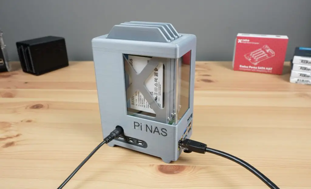
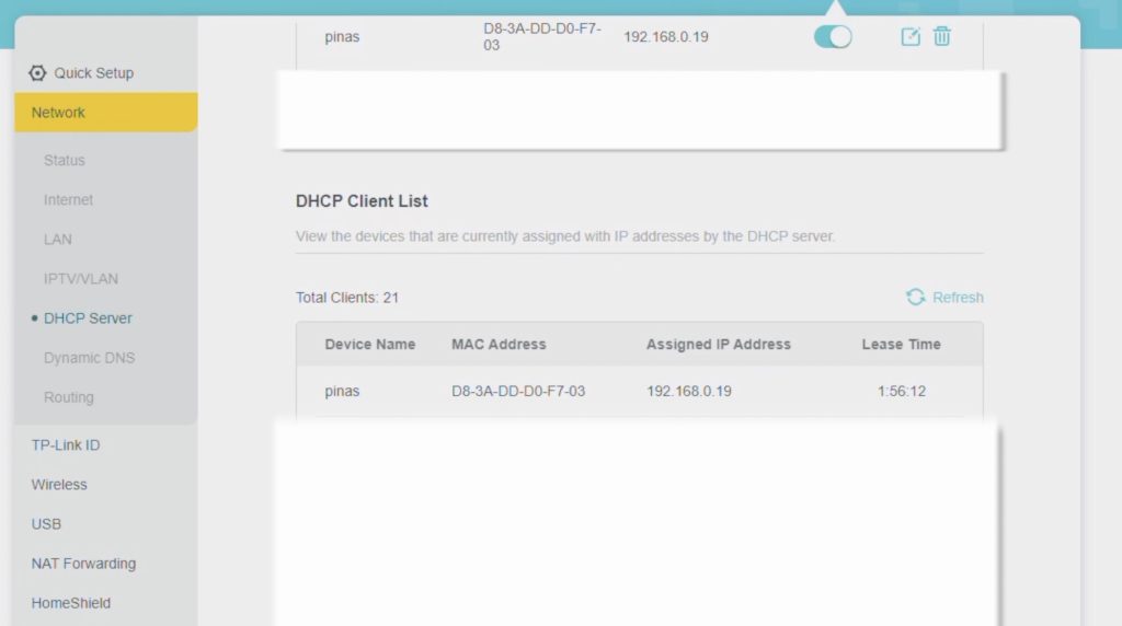
Once power has been turned on, leave the NAS for a few minutes to boot. It usually takes a bit longer to boot up the first time. We can then try to find it’s IP address. This can be done through your network’s DHCP table by logging into your router or by using a utility like Angry IP Scanner. We’re looking for a device called Pi NAS that has recently joined the network.
We can then SSH into the Pi using its IP address to continue setting it up. I’m using Putty on my Windows PC to do this.
Now we need to copy and run this line from the OMV installation instructions GitHub repository to run a script to install OMV on our Pi:
sudo wget -O - https://github.com/OpenMediaVault-Plugin-Developers/installScript/raw/master/install | sudo bash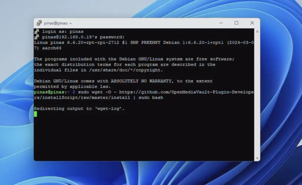
The installation script takes about 5 minutes to complete and, if successful, should take you to a screen similar to this telling you that the pi is rebooting and your SSH session will be terminated.
When your Pi has rebooted, there is one more thing we need to do before opening up OMV to set up the software. We need to enable the PCIe port on the Pi as this is disabled by default. None of the connected drives will show up until we edit the config file below;
sudo nano /boot/firmware/config.txt We need to add the below two lines and then reboot the Pi.
# Enable PCIe Port and Set to Gen 3 Speed
dtparam=pciex1
dtparam=pciex1_gen=3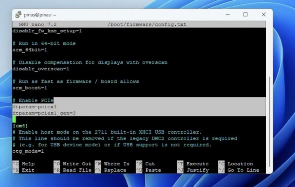
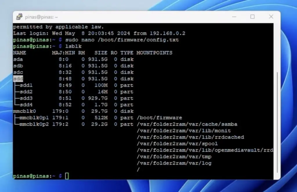
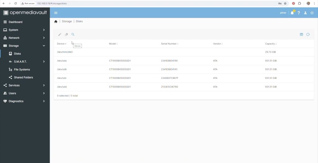
You should then start seeing the activity lights on the drives light up and they’ll show up in the terminal.
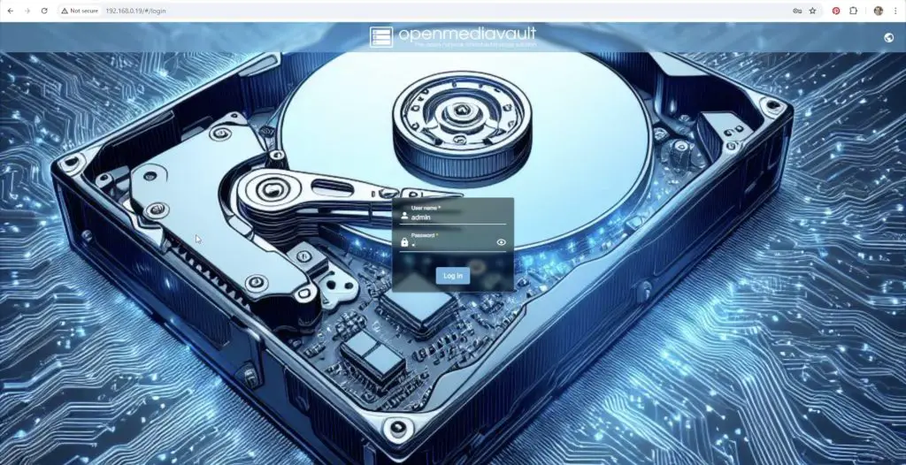
Now that all of the installation and configuration work is done, we can access the OMV workbench through a browser by entering the Pi’s IP address. The default login is admin and openmediavault, which you’ll want to change immediately.
There are loads of good guides on setting up OMV, so I’m not going to go through it here in detail but these are the steps I followed:
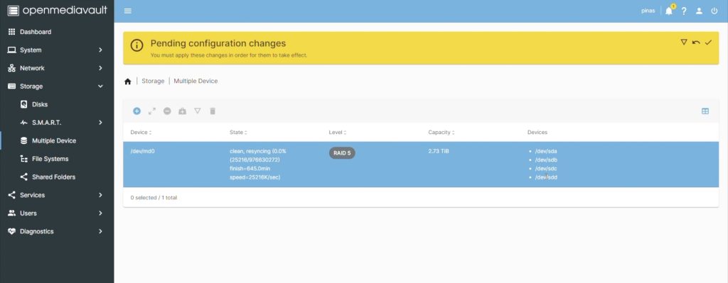
- Set up my four drives in a RAID 5 configuration to balance storage capacity and redundancy. This gives me a total usable storage capacity of 3GB.
- Create a storage volume on the array.
- Create a shared folder on the storage volume.
- Enable SMB file sharing for Windows.
- Create a user account with permission to access the shared folder.
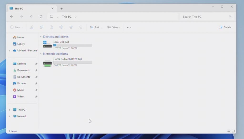
With that complete, we can map the network drive to our PC and can then start using it.
So now let’s see how good it is.
Testing The NAS’ Speed
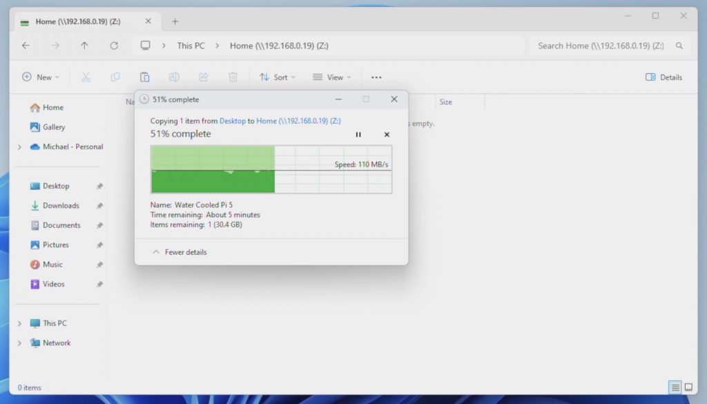
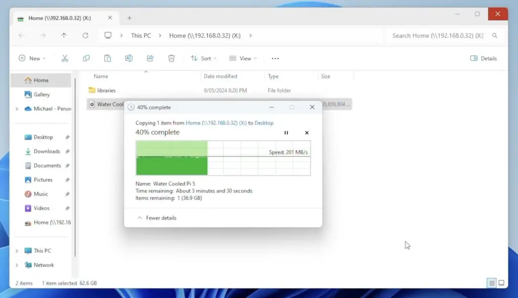
Copying a single large video file to the NAS, we get an average speed of about 112MB/s which is about 900Mb/s.
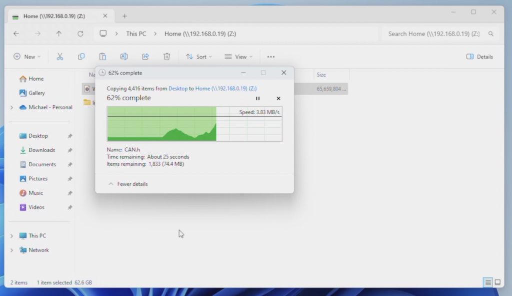
A folder of 4,500 smaller files and directories is obviously a lot slower than the single large file but is comparatively as fast as copying them locally.
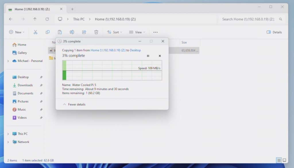
Copying the large video file from the NAS, we get a similar average speed of about 110-112MB/s.
This looks like we’re saturating the gigabit Ethernet port on the Pi, so next I tried plugging a 2.5G Ethernet adaptor into one of the USB 3 ports on the front.
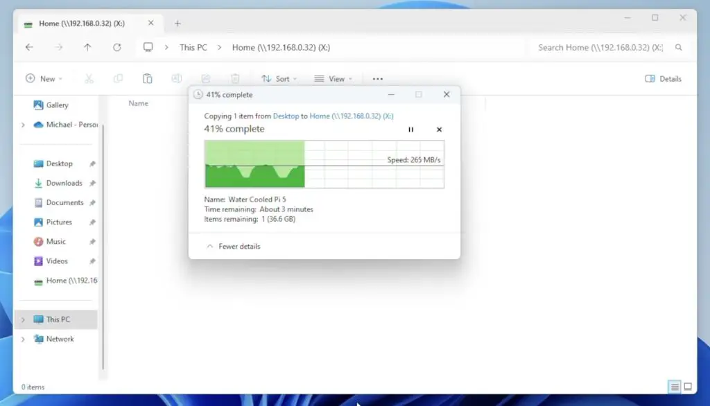
This made a significant improvement. I instantly got an average of 260MB/s copying files to the NAS although there were a few dips down to about 120MB/s and spikes a little over 270MB/s , so that’s close to saturating the 2.5G ethernet connection which is a great.
Copying the same large video file from the Pi to my PC, I got a little under 200MB/s.
Given the significant speed increase, this is a worthwhile upgrade for less than $20. It really is a bit disappointing that the Pi 5 doesn’t come with 2.5G Ethernet as this makes a big difference to performance for projects that require a large amount of data to be transferred.
Power Consumption
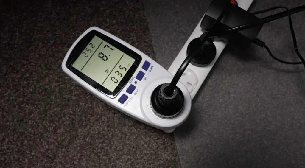
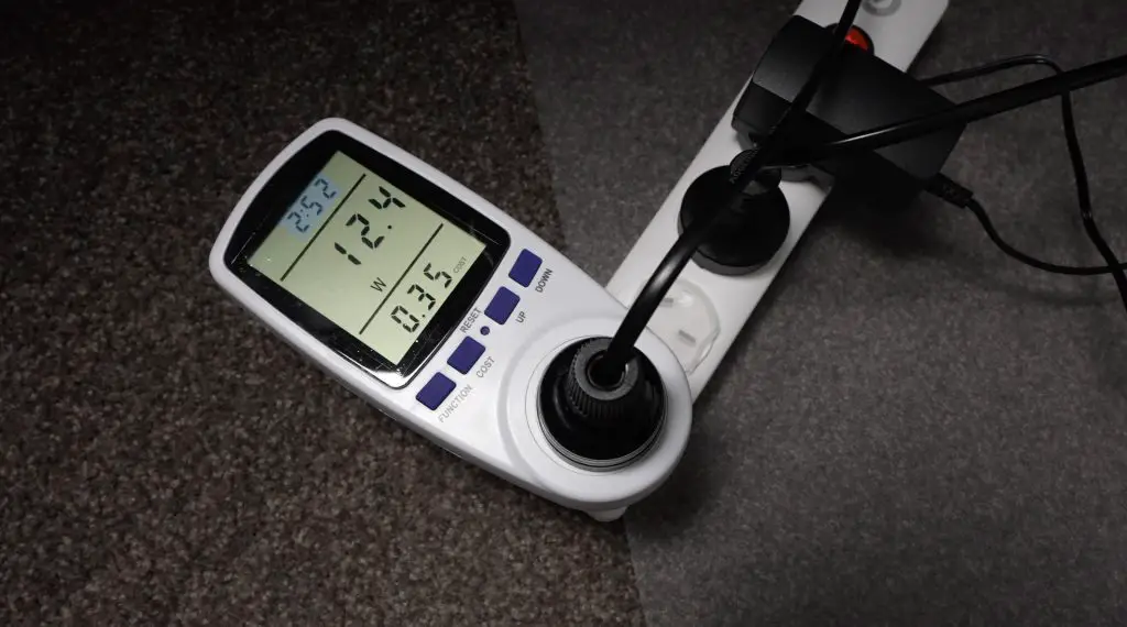
Power consumption is where this NAS shines, especially with its solid-state storage. At idle, the NAS uses a miniscule 9W and consumption only goes up to around 12 under load. This is significantly less than the 30-40 watts that a typical 4-bay home or small office NAS uses. My Asustor NAS uses about 18w at idle with the drives spun down.
Final Thoughts On My Raspberry Pi 5 Based NAS
So that’s my new 4-bay Pi 5 NAS complete. I’m really impressed with the speeds that I managed to get using the 2.5G Ethernet adaptor. This highlights one of the weaknesses in the Pi 5, which really should have been designed with a 2.5G Ethernet port given its relatively recent release date.
Cost-wise, this is not the most affordable NAS on the market but it’s also not particularly expensive considering it is very versatile and customisable, running open-source hardware.
The main NAS components, being the Pi ($80), Radxa Penta SATA Hat ($45), Cooler ($5), Power Supply ($15), MicroSD Card ($5) and Fan ($15) come to $165 – which is around the lower end of what a commercially available 4-bay NAS would cost, albeit without the DIY work required.
The NAS is really power efficient for those who live in an area or country where power is expensive. Running this NAS 24/7 for a year would cost less than a third of what a traditional NAS would cost to run.
Let me know what you think of it in the comments section below and feel free to send photos through of your build if you 3D print your own.
Man your CAD modelling is on point! Awesome design, very cool. And great tip on using the ethernet adapter.
I hate OMV though. Whenever I’ve tried it, it inevitably breaks and you have to start all over again. I just load up Dietpi and use samba. Any regular backup jobs can be sorted though Crontab. Fire and forget. And any extras, well… there’s always a Docker for that
Excellent build though and great write-up. Thanks
Thank you Lee! I haven’t had any issues with OMV yet but I like your solution, its clean and easy to implement.
3 TB iso 3GB
Hello Michael
I guess the capacity of that NAS is 3 TB not GB. It is a very smart solution. Well done.
Kind regards, Martin
for his setup, 4 sdd 500GB on RAID 5, the total capacity is 1,5 TB
Great design – I love, love, love this solution! Printing plate 1 now on my X1C.
Great design, clear instructions, thorough description and testing – love it!
I wonder if you’d be willing to share your Fusion360 design? Or at least Housing Bottom+Window+BrassInserts? I am also a Fusion360 user, and would like to customize only the text of the box (LUVNASP1, LUVNASP2, …). (I’d also adjust to insert the nuts during print, but that’s of lesser importance. I have designs on replacing all my existing NAS (there are three) since I’ve been plagued with controller problems recently. Old equipment; time for a refresh.)
I understand if you don’t wish to share that, but thought I’d ask.
Use a slicer to convert 3MF to STL, then use FreeCAD to create a STEP model file to work in Fusion (you can find how online), then you are able to edit the final design to your specifications.
what are the dimensions for the clear lexan x,x,2mm
great great work
The acrylic is 108mm x 83mm
Hi
What about the dimensions of each side of the window? I was thinking about buying two acrylics and then glue them with sillicon.
Great project!
I was just wondering about the mounting trays. Are they specific to the SSD you’re using? Will they work with others?
Thanks
They’re designed around generic SSD dimensions so should work with other standard size drives.
Hi. This is excellent. I’ve been testing the NAS part and now need to print the enclosure. But I can’t find the variants you describe. I need the No Window, with Brass Inserts but can only see 2 of the 4 variants. Can you upload this and/or share the F3D model? Paul
Hi. This is awesome. But, is it possible to change the ssd with 3.5inchi hdd?
Thank you
Agung
Not in this enclosure but yes you can use 3.5″ drives with the Radxa hat.
I’ve just finally finished with my PiNAS (specifically the case part), it was quite a journey. I really enjoy this implementation being a sweet spot between speed, price, power consumption and upgradability. Also having full control of the services in OMV containers is a huge bonus.
As for the case design, I had to do some modifications to your design in order to fit all of the mods that I’ve added to my hardware. The mods include bigger 60mm fan, GPIO splitter, external programmed (scripted) eInk screen with Status Information (many other options available here) and higher standoffs which were used to avoid damaging heat sink fins at first, but later required to accommodate GPIO splitter, which raises the Penta SATA Hat 16mm higher than normal. So I had to adjust many of the hole locations on the box, add new ones and extend the box to be taller. I was fully prepared to have screwed up the measurements, but to my surprise, things turned out to be super good enough overall. You’ve asked me several weeks ago on your YouTube video about using different standoffs. For this specific implementation I had to mix and match default ones with the black nylon ones. Also using black nylon screws on top makes the look more murdered out.
Here are some pictures of the build. Print quality is not the best, but it’s good enough: https://imgur.com/a/sD2OjYV
I have questions, it would be awesome if this thing can have a hdd and a psu in its case raid 5(4xssd) + backup hdd maybe the 2.5gb integrated all to one side
Super nice project!
On Github you recently mentioned a redesign with an 80 mm fan… Would you share the redesigned model as well? Please!!! 😉
Hi Michael – I have experience in building my computers, but not with Pi so my apologies if this is a stupid question.
Why your BoM includes a “12V 3A Power Supply”? Online I read that the Raspberry Pi 5 requires 5A to supply multiple devices. Is it because SSD do not require a lot of power?
Apologies for my previous post. if possible pls delete it.
Thank you!
The Pi ‘requires’ up to ~27W, which is ~5A@5V – the CPU tops out at about ~10W. The hat requires 12V input and can provide 5V to the Pi via the GPIO pins.
If you check Radxa’s documentation for this board (linked below), they state you can use the official Raspberry Pi 27W PD adapter if you are solely using solid state drives and no other peripherals. Unsure why the author went this route, maybe didn’t have the official adapter to hand?
Excerpt:
“When used with Raspberry Pi 5, it supports three power supply modes to adapt to different usage scenarios:
Use a Type-C adapter to power the Raspberry Pi 5
Use a DC 12V adapter to power the Penta SATA HAT
Use a D-shaped 4PIN from an ATX or SFX power supply to power the Penta SATA HAT”
https://docs.radxa.com/en/accessories/penta-sata-hat/penta-for-rpi5
During my initial testing, the Pi wouldn’t boot with the four SSD’s and the 2.5Gb Ethernet adaptor when powered using the official Pi 5 USB power supply. So instead of switching power supplies, I just used the supply to the Raxda hat for the whole project.
The Pi’s official power supply is 5V and 5A, which provides up to 25W. I am using a 12V 3A supply, which provides up to 36W. The increase in voltage from 5V to 12V makes up for the drop in amps from 5A to 3A.
Thanks, Mike, for the article! I finally got all of my parts in and started on it. What I can’t wrap my head around is how you bend the acrylic with ease to fit exactly in. I don’t see any measurement lines when you’re using the tool. I cut the 108mm X 83mm with a hand tool. Crooked lines and 4 cuts to my fingers later, I then heated up the tool for ~20min using the same arc one that you used and listed, and it looked to burn too much into the acrylic. Going to have a neighbor laser cut a new one out for me. The case has slight lines on the outside that show where the divots are for the window, so I plan on using the bigger bend tool with larger surface space to head up the panel and then line it up with the outside lines of the case and bend around. Will only let the tool heat up for a few minutes this time and pray it doesn’t start to melt the case.
I am not crafty, any advice for this fool? Thanks!
Hi Skyler,
I’ve added the SVG file for the window to the section discussing bending the window above. The window is 108mm x 83mm as you’ve stated and the centre of the bend should be made 45mm from the edge.
There may be an issue with the material or type of acrylic you’re using. To make a bend like this I allow the bender to preheat for about 2-3 minutes and I’d then clamp the bend line for about 20-30 seconds to heat it up enough to make the bend. Definitely nowhere near 20 minutes.
Hi Michael,
If it’s not a big ask, can you modify the enclosure and create an opening for a stat display? May be above the opening for the fan ?
Great project, congratulation
I am not able to make it.
Anybody knows where I can buy one 4TB RAID 1 with a cloud function and a back-up battery system, that is plug and play ready?
Thank you in advance
Regards
Michael. I’ve built it but struggled as the brass insert version (no window) simply didn’t have enough material for the inserts. I found the melting process damaged the plastic too quickly and hence the components wouldn’t align when assembling and/or the inserts ended up having plastic in them so screws wouldn’t fasten.
I’m hoping you’d agree to share the F3D model (even privately) so I can make my own adjustments?
I don’t know if this was addressed already, but am wondering what power source and pin connections were used for the cooling fan for the ssd’s?
There is a fan power underside of the penta sata hat if you used the one on the pi for the CPU fan/heatsink
This build sounds super interesting! I love that you’re upgrading from the Pi Zero 2W to the Pi 5 for a more powerful NAS. The Radxa Penta SATA hat seems like a game-changer with its 5 SATA ports. I’m curious, did you run into any compatibility issues while putting this together? And how’s the performance of the 4 Crucial SSDs so far? I’ve always wanted to build my own NAS but been a bit intimidated. This article might just give me the push I need!
Hey,
I hope you’re doing well! I wanted to ask—I’m currently not in a position to get the enclosure printed here in India due to limited resources.
Would it be possible for you to ship a printed version to me, if that’s okay and you’re able to do so?
Totally understand if it’s not feasible, but I thought I’d check. Thanks so much either way
I give it a try with 4x 2TB SSD build to a Raid5 with OMV-MD Plugin. But after 1 day i lost the raid 5 (one disk is missing), This happened 2 times. I try to install everything once more, then i quit this project,
Hey,
I’m struggling with assembling the button adaptor. I understand it is meant to slide onto the brass corner “standoff” screw . You also mention tight fit, but for me its way too narrow. Did you use the original standoff screws from the radxa kit? Or something slimmer? Alternatively would you recommend trying to print the adopter again at 105 or 110% the size to increase the eyelet? I’m worried the pivot length will get out of proportion though..
Projeto Incrível. Seria possível colocar uma ROCK PI4Bplus no lugar da Raspberry pi 5, pois tenho uma sobrando de outro projeto e gostaria de fazer um servidor semelhante ao seu
This is a fantastic build! I really enjoyed reading about your journey, especially the detail you went into when designing the enclosure. The performance numbers with the 2.5G Ethernet adapter are impressive. Considering the energy efficiency, this seems like a very compelling NAS solution. If you’re looking for other creative projects, I found a fun website that turns photos into cartoons instantly. Check it out at AI Cartoon Generator. Great work!
This is a fantastic build! I’ve been thinking about setting up a NAS myself, and your detailed guide using the Raspberry Pi 5 is very helpful. The 2.5G Ethernet adapter really seems to boost performance, and I appreciate the breakdown of the costs and power consumption. If you’re looking to flesh out the personalities of those characters you’ll be storing your files for, check out Character Headcanon Generator, it’s a great tool.
This is a fantastic build! I really appreciate the detailed breakdown, especially the design considerations for the enclosure. The 2.5G Ethernet adapter makes a huge difference in performance, and the power efficiency is a significant advantage. It’s inspiring to see how a custom NAS can be put together. If you’re looking for a way to visualize your digital life’s impact, check out AI Beauty Rating. It might just give you a fresh perspective!
This is a fantastic build! I especially appreciate the detailed breakdown and the 3D-printed enclosure design. The performance with the 2.5G Ethernet adapter is impressive, and the power efficiency is a huge plus. The project is inspiring and I’m considering building my own NAS. If you are looking for ways to easily generate captions for your photos and share your own builds, check out AI Describe Image. It’s a great tool!
Hi Michael, love your case design, but I have a question for you. As it stands your NAS will only be accessible locally through your router, have you investigated how to create a secure tunnel to access the NAS from anywhere? I so could you give us the details of how it’s done?
Hey did you have to do anything special to get the usb network adapter to work? I tried just plugging it in and restarting and it just wont connect. Followed all the instructions above but it does say anything.
Love this, just winced when you used R5, I’m a storage professional and have spent far too much of my career suggesting people not use R5 only for them to come back later asking how to recover their damaged array – friends don’t let friends use R5 🙂
For the Fan can you point specifically with pictures where do I have to soldering the wire on the radxa board? I am not a electronic savvy guy and I cannot see where the wires are soldered.
Thank you
I take it that as the system stands you can only access it locally on the same network. How do I go about accessing it remotely?
Yes, you’ll only have local access. You can set up remote access through a service like Tailscale.