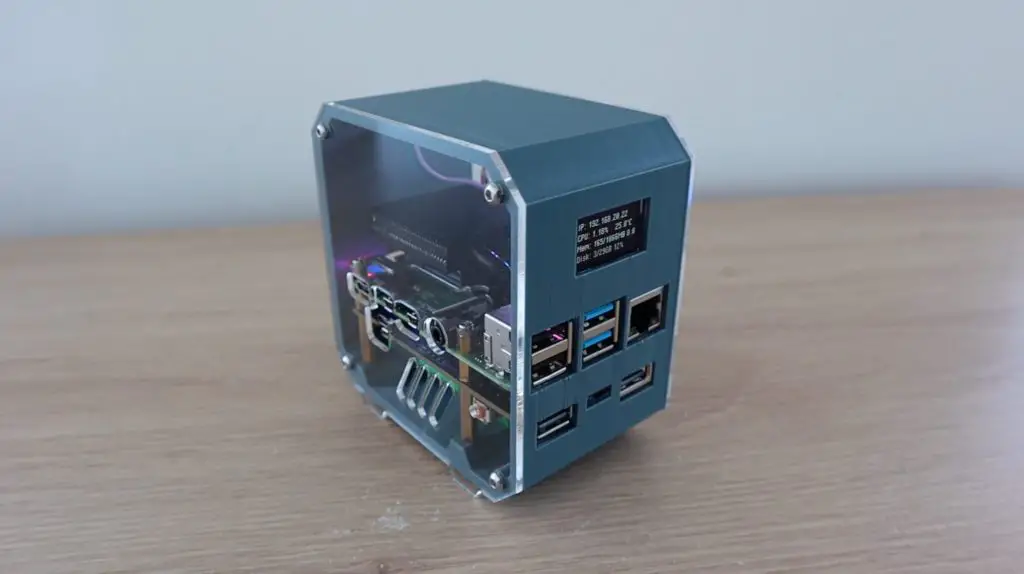
Today we’re going to be building a mini Raspberry Pi server with a built-in UPS and OLED stats display. A Raspberry Pi makes a great server for a NAS or for media streaming, home automation, or even a home security hub for your cameras. All of these projects would benefit from having a built-in UPS to ensure that the Pi is kept running in the event of a power interruption.
Here’s a video of the build and the UPS running, read on for the full write-up. You can also buy a case kit, which includes all of the components you need to assemble your own mini server.
What You Need To Build Your Own Mini Server With UPS
- Raspberry Pi 4B – Buy Here
- 32GB Micro SD Card – Buy Here
- UPS Module – Buy Here
- Low Profile Ice Tower – Buy Here
- 18650 Lithium-Ion Cells – Buy Here
- 128×64 I2C OLED Display – Buy Here
- 15cm Ribbon Cable – Buy Here
- 5V 3A Power Supply – Buy Here
- 4 x M3 Nuts – Buy Here
- 12 x M3x8mm Button Head Screws – Buy Here
Other Equipment Used:
- Portable Monitor – Buy Here
- 3D Printer: Creality Ender 3 V2 – Buy Here
- Laser Cutter: K40 – Buy Here
- Screwdriver – Buy Here
Some of the above parts are affiliate links. By purchasing products through the above links, you’ll be supporting my projects, with no additional cost to you.
Unboxing The GeeekPi UPS Plus Module
The UPS we’re going to be using is this UPS module that GeeekPi sent to me to share with you.
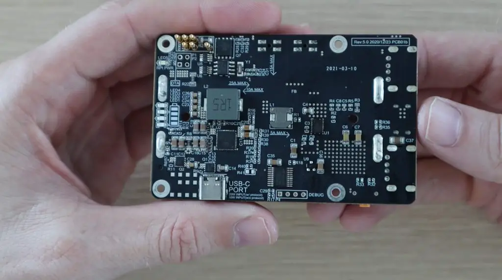
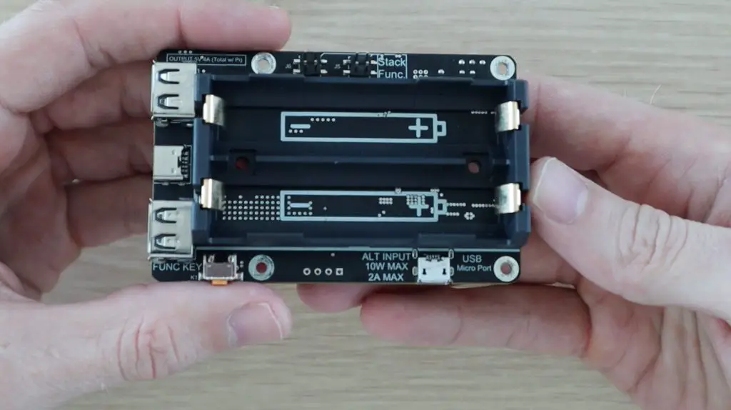
It looks like a relatively simple board, with a prominent battery holder on one side, but it actually has a number of great features, including power management circuits and I2C communication, enabling low voltage safe shutdown and automatic restarts.
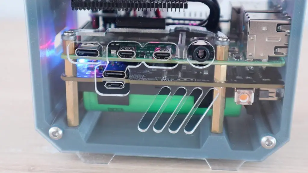
Power is supplied to the UPS through either USB C or a micro-USB port, with the board taking advantage of the USB 3.1 protocol to allow a higher input power through a higher charging voltage.
The board also has three USB ports on the front, two full-size ports and one USB C port, that allow a combined output of up to 4A including the Pi’s consumption. There is also a battery monitor in the form of four blue LEDs that light up and/or flash to indicate the current battery level. And lastly, it has a function button on the side.
This is the most recent 5th revision of this board, which was completed in December of last year.
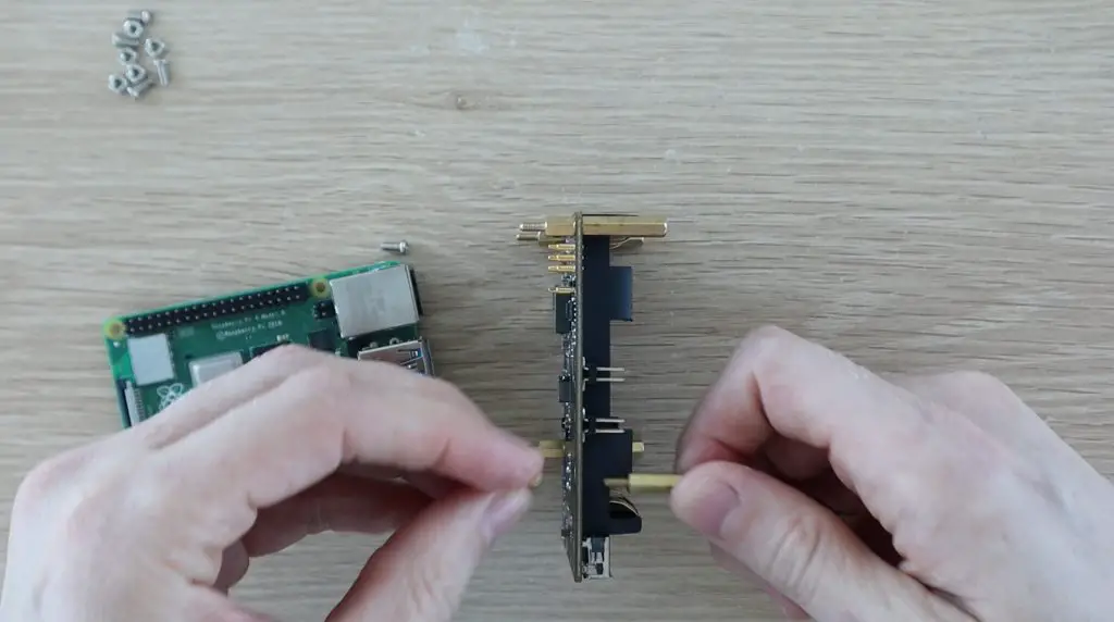
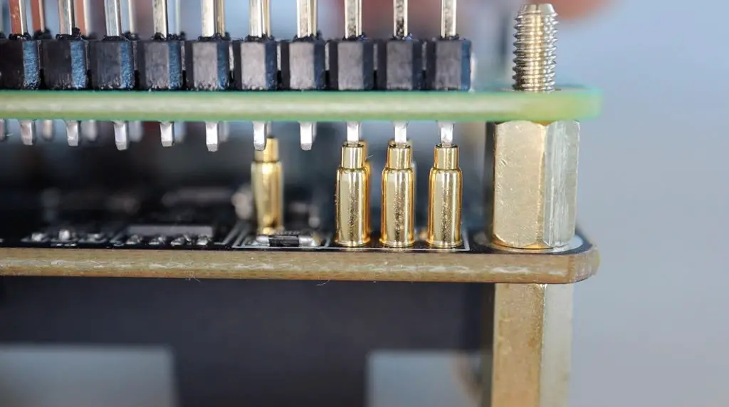
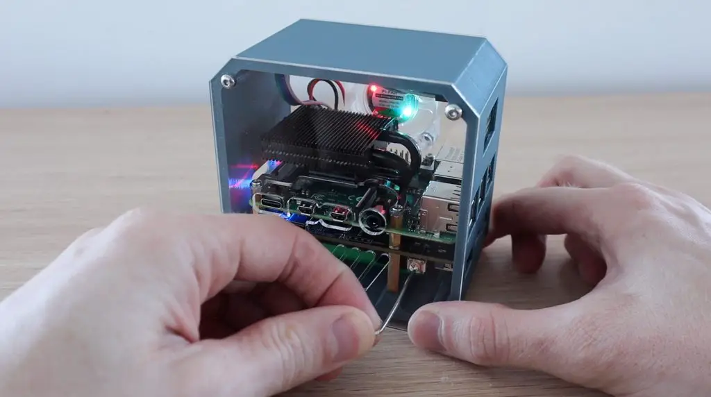
The UPS is mounted onto the PI using some supplied brass standoffs and nuts. Unlike most Raspberry Pi hats, the UPS is designed to mount underneath the PI and has these little spring-loaded gold contacts that make contact with the underside of the header pins. This is a really nice feature as it keeps all of your GPIO pins available for other connections.
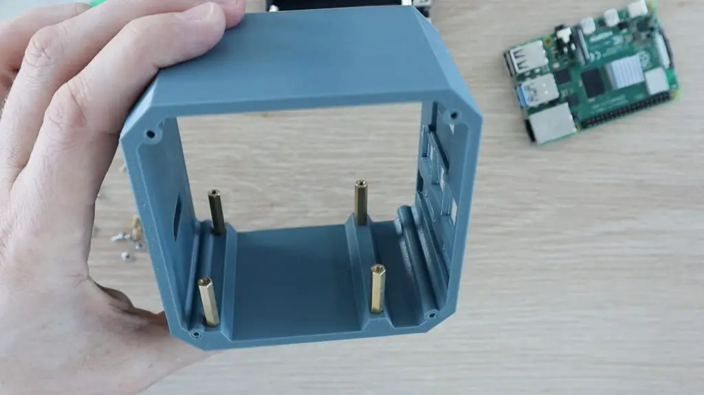
The board takes two 18650 cells that are connected in parallel, so the UPS boosts the voltage of the cells to the 5V required by the Pi. I’m going to be using some 2500mAh cells that I have left over from a previous project.
You may have also noticed in the video that the UPS turned on as soon as the first battery was inserted. You can then turn it on or off using the function button.
The UPS also includes an acrylic base plate to mount it onto. We’re not going to use this as we’re going to be building the Pi and UPS into a custom case.
Building The Mini Raspberry Pi Server
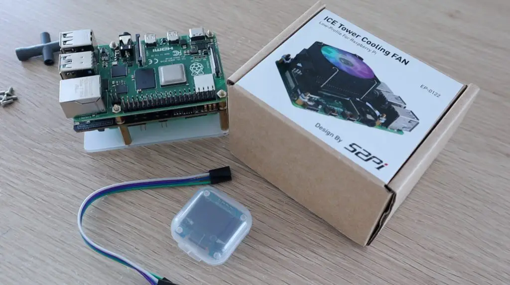
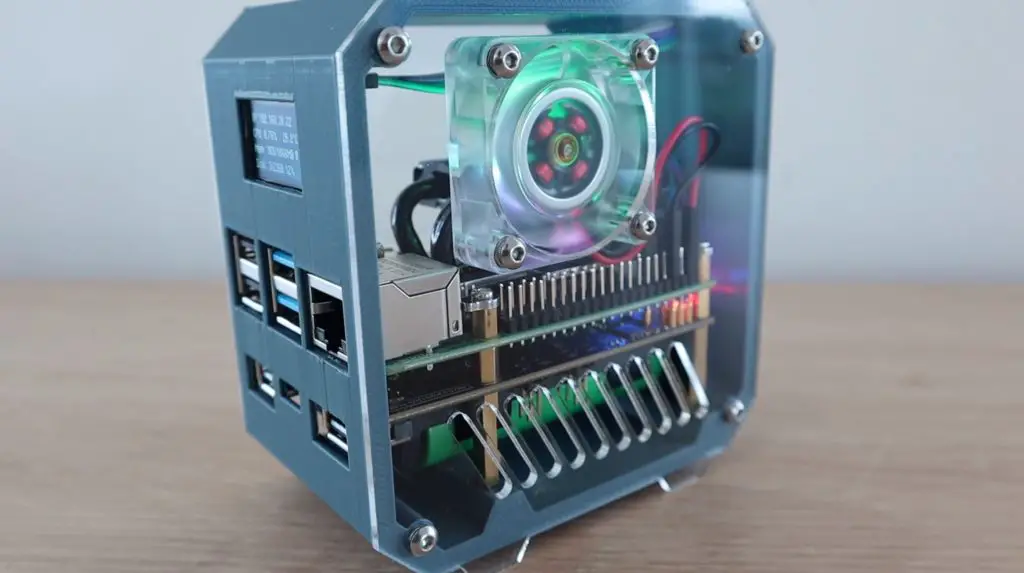
To build the mini server, I’m going to use a low-profile Ice Tower to provide cooling to the Pi and I’m going to add an I2C OLED display to the front of the case to display some performance stats for the Pi as well as stats for the UPS.
I used my previous Ice Tower Pi case as a starting point and then modified it to accommodate the UPS underneath the Pi. I had to move the OLED display up a bit to clear the top of the Pi’s USB ports.
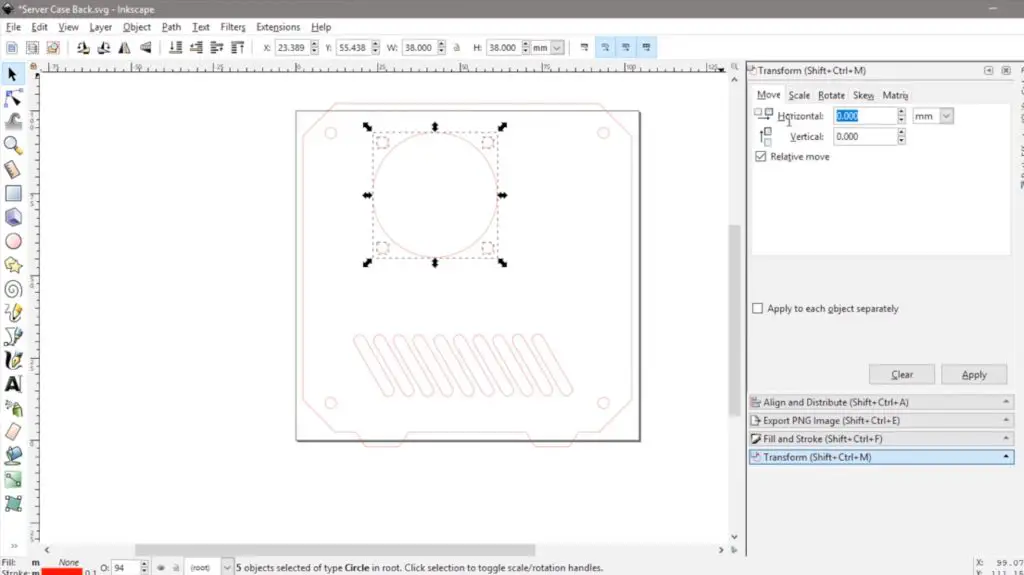
Designing The Server Case To House The UPS
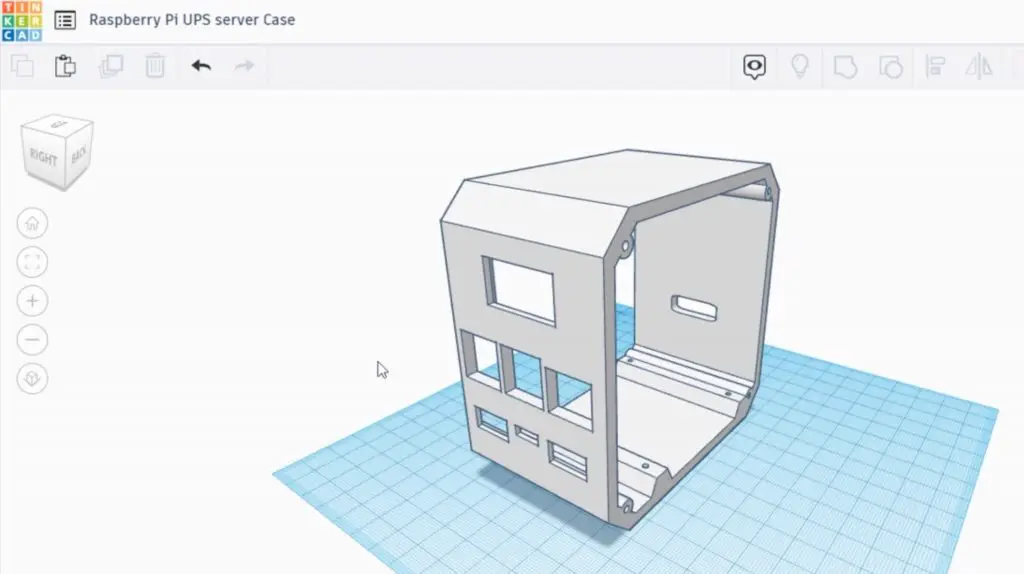
Download the 3D print and laser cutting files or buy a complete case kit.
I then 3D printed the case on my Creality Ender 3 V2 in grey PLA with a 15% infill.
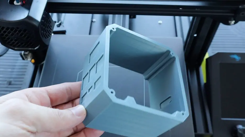
I then also had to make some modifications to the clear acrylic side panels. I moved the Pi ports higher up and added the additional cutouts for the UPS underneath them. I also added a couple of vent holes along the bottom so that air would be forced around the Pi to cool the UPS and batteries.
With the case and side panels made up we can start installing the components into the case.
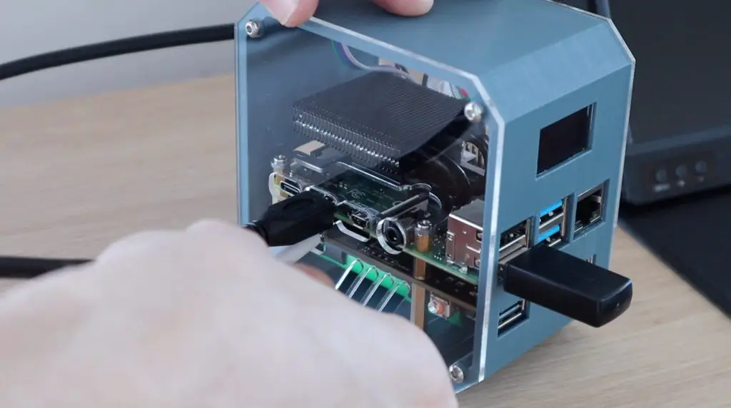
Assembling The Server With UPS
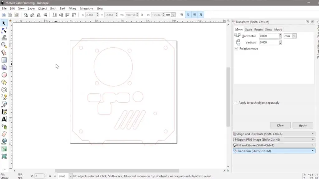
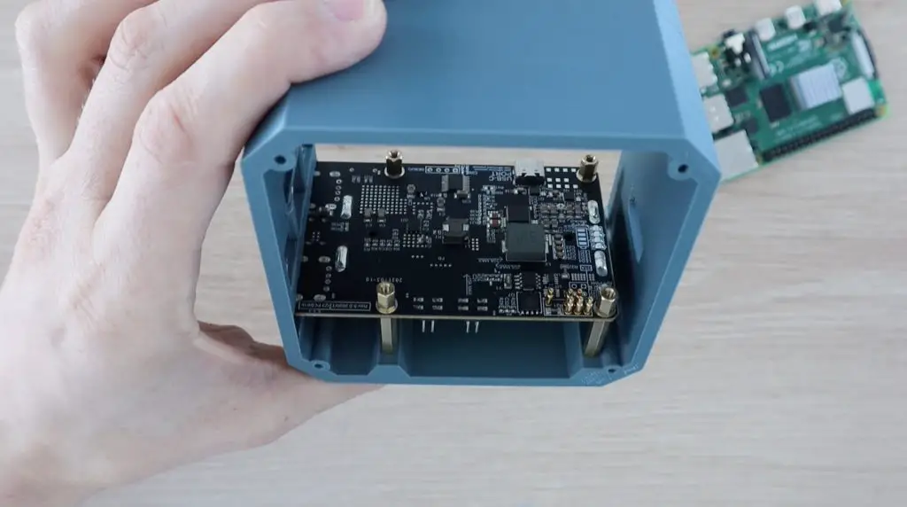
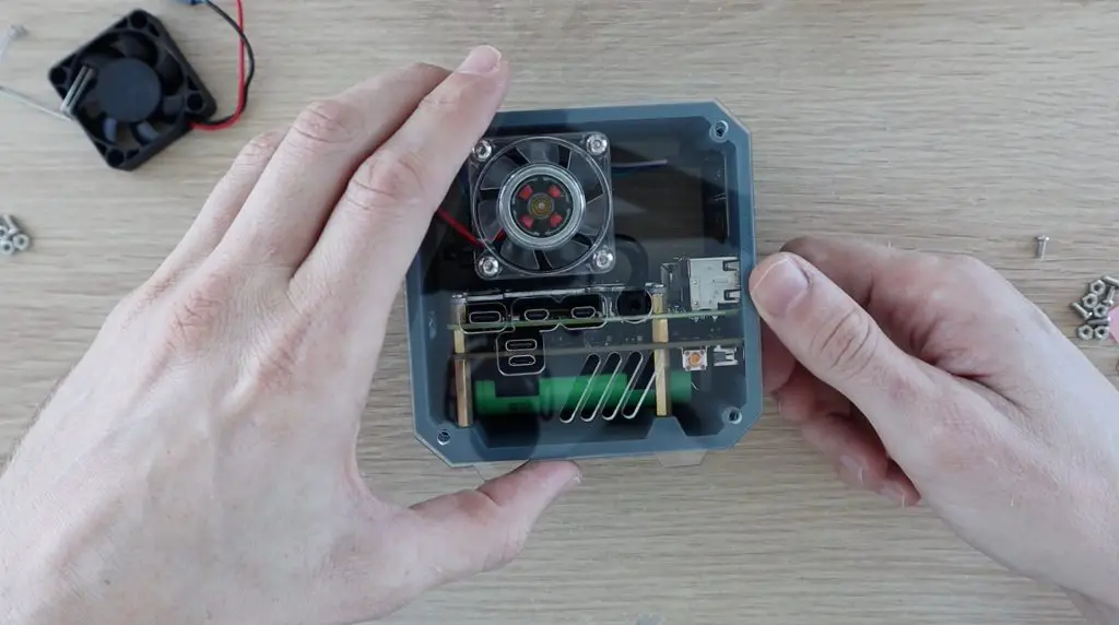
I started by screwing the longer brass standoffs into the base of the case. These are quite tight initially, but need to be so that they don’t move when plugging or unplugging peripherals into the Pi’s ports.
I then put the batteries into the holder and mounted the UPS. You need to be careful from this point as there isn’t any way to physically isolate the batteries, so some parts of the UPS are powered and you risk shorting and potentially damaging the board if it touches the metal standoffs in any area it’s not supposed to.
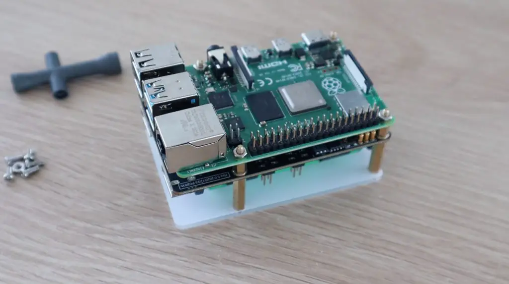
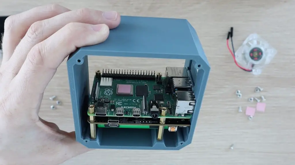
The smaller brass standoffs then hold the UPS in place and we can then mount the PI onto them, making sure that the terminals are properly seated on the GPIO pins.
The Pi is then held in place with the standoffs from the Ice Tower.
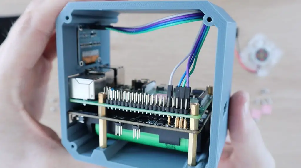
Before installing the Ice Tower, I’m going to install the OLED display.
This just pushes into the holder in the case and I’ll connect a ribbon cable to the pins on the back to plug it into the Raspberry Pi. These provide power to the display and connect to the Pi’s I2C pins.
The connections are typically:
- GND to Pin14 Ground
- VCC to Pin1 3.3V Power
- SCL to Pin5 SCL (GPIO3)
- SDA to Pin3 SDA (GPIO2)
Have a look at my detailed guide on Connecting an OLED Stats Display to your Pi for more information on this.
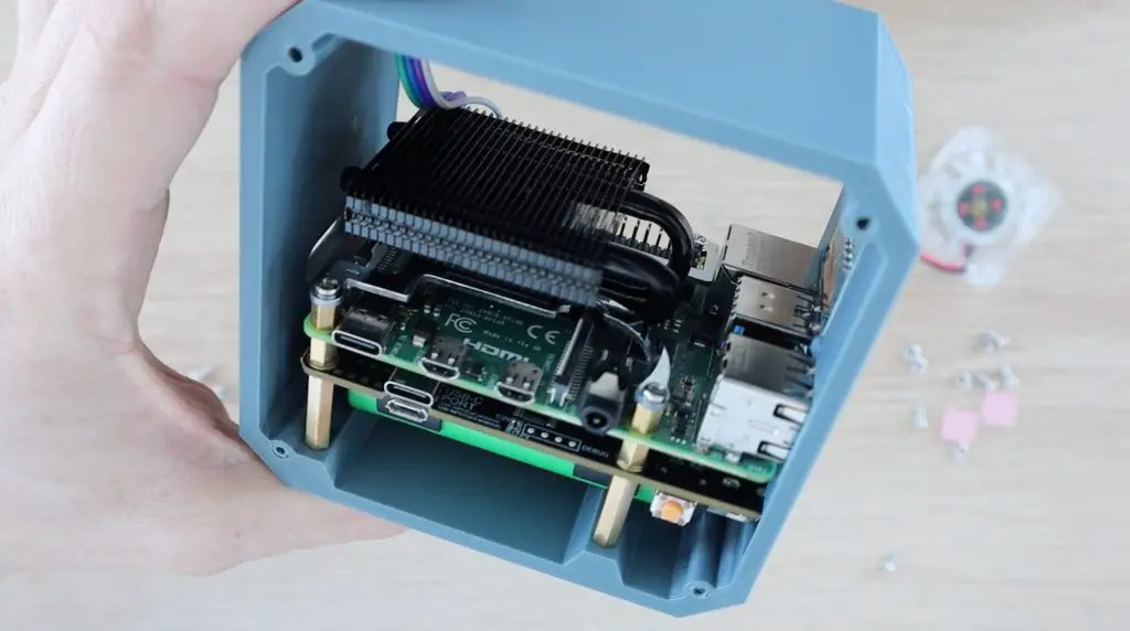
Now we can install the Ice Tower. I removed the fan from the heat sink as I’m going to move this onto the side panel to push air into the entire case. I’m going to use the RGB fan that was supplied with the Ice Tower as an alternative to the plain black one.
Screw the Ice Tower onto the Pi, again making sure that you don’t touch the metal bracket onto any of the components on the Pi or the GPIO pins. Although the Pi may look like it is still off, rather be cautious.
Installing The Side Panels
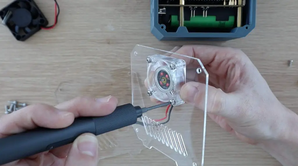
I mounted the fan onto the side panel by pressing some M3 nuts into the pockets on the fan and then screwing the fan into place with some M3x8mm button head screws.
I then tried to fit the side panel. It was at this point that I saw that the Ice Tower is wider than the standard Ice Tower and clashed with the back of the fan. So I had to redesign the side panels to move the fan to the other side.
I then mounted the fan onto the modified side panel, again using the M3x8mm button hex head screws.
I screwed the two side panels onto the case using some more M3x8mm screws.
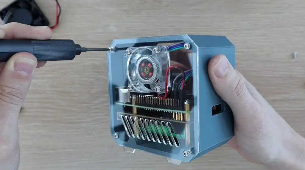
The last thing to do was to put the SD card into the Pi and power it up. I’m using a fresh install of Raspberry Pi OS.
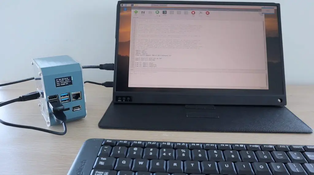
Programming The Raspberry Pi
With the mini server all assembled, we now need to program the Raspberry Pi so that the automatic shutdown works and to get the UPS stats to show up on the OLED display.
The Pi booted up as soon as the power cable was plugged in, so it looks like the UPS was working correctly so far.
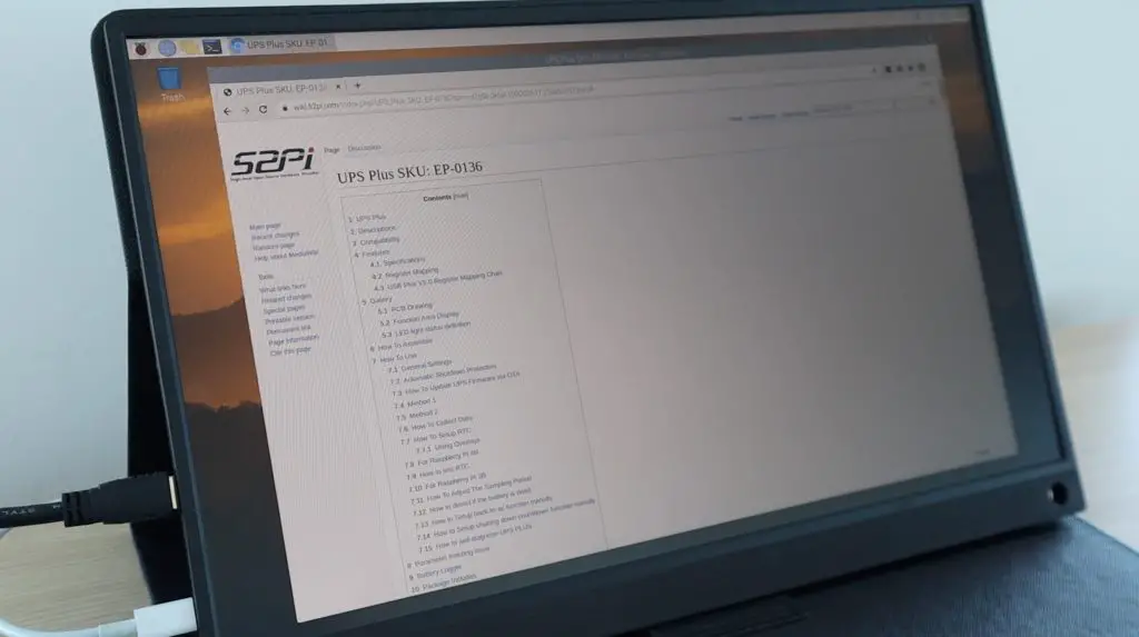
I’m going to go over to the UPS Plus Wiki to see how to install the script that allows automatic shutdown and see what other UPS information is available on the Pi.
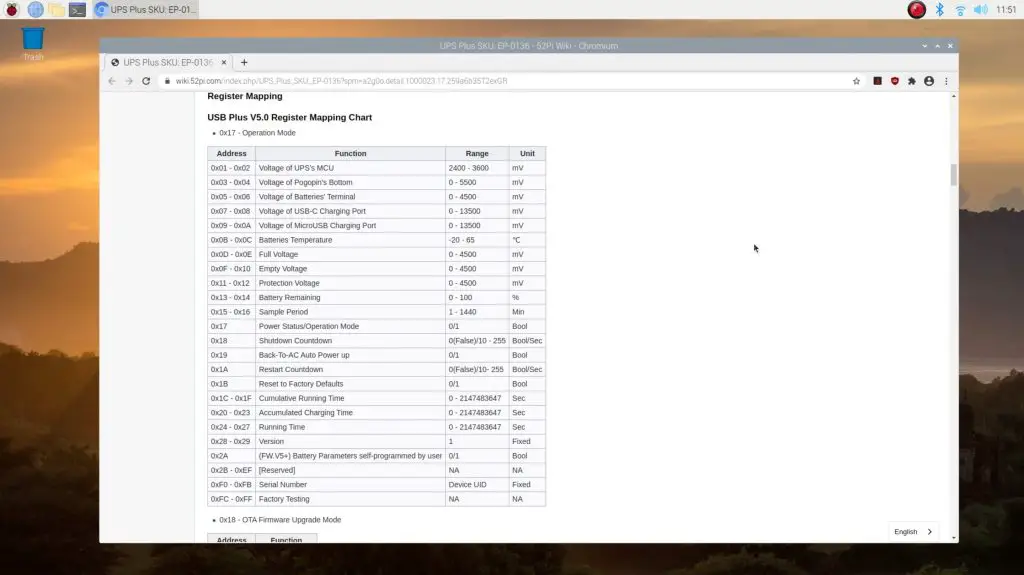
You can see all of the information that is available to be read by the Pi on the Register Mapping chart. It’s a pretty comprehensive list. All of these metrics can be accessed by the Pi through the I2C interface, we can then display the ones we’d like to on the OLED display.
It’s a pretty straightforward process to download the example script that allows you to make changes to the general settings and access the available data on the UPS.
First, ensure that I2C communication is enabled in your preferences menu. Then install the smbus2 library by entering the following command in a new terminal window:
pip install smbus2You can then download the GitHub repository by entering:
git clone https://github.com/geeekpi/upsplus.gitInstalling The UPS Automatic Shutdown Script
The install the automatic shutdown protection that signals the Pi to shutdown when the battery level becomes critically low, we just run a single line.
curl -Lso- https://raw.githubusercontent.com/geeekpi/upsplus/main/install.sh | bash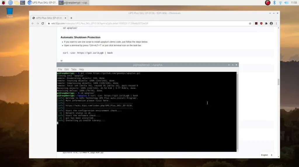
Displaying The UPS Stats On The OLED Display
Next, we’ll have a look at the example script and the script that I used previously to display the Pi’s performance stats and integrate the two to produce a second stats display for the UPS that will show us some key UPS information. I’ll also add some code to switch between the two display screens every few seconds.
If we run the example script in the GitHub repository that we downloaded earlier, we get a printout of almost all of the stats available on the UPS.

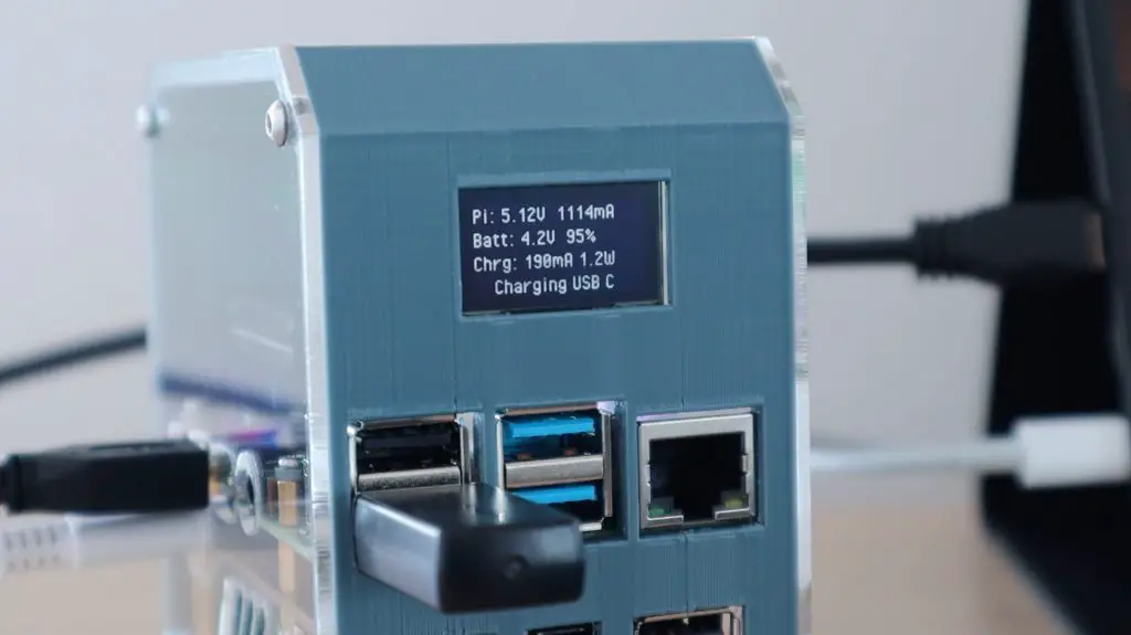
The information I’m going to put on the UPS display is the Pi’s voltage and current being drawn, the battery voltage and capacity, and lastly the charging current and power and charging status. This will allow us to keep an eye on how much power the Pi is using, the state of the UPS battery, and whether we’re charging or discharging the battery.
You can download my script below. You’ll need to also download the font PixelOperator.ttf from https://www.dafont.com/pixel-operator.font and then unzip the contents of the download and paste the font into the same folder as the stats.py script.
Dan has made some tweaks to the script to improve stability and has documented the automatic startup of the script on boot, you can find these in his Github repository – danb35/raspi-ups-stats.
Let’s try and run the script and see what we get on the display.
Next let’s test the UPS by pulling out the power cable and make sure that the Pi keeps running and that the display shows us the battery level and correct charging status.
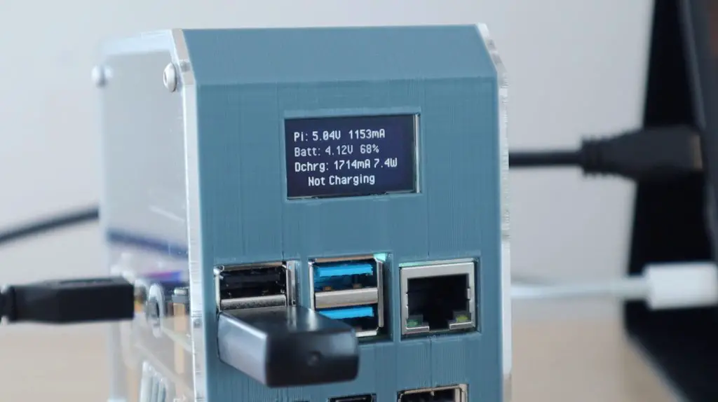
So it looks like that’s all working correctly.
Further Testing The UPS Plus Module
I was able to get just under an hour and a half of runtime from a fully charged set of batteries. This would obviously depend on the capacity of your batteries. For most people, this would be long enough to ride out a short power interruption and your Pi would be safely shut down if the interruption lasted longer than this.
I also wanted to see if I could plug the display’s power cable into the UPS as well, powering my whole setup from the UPS.
The display came on and it looked like the UPS had enough capacity to power the display as well, although this is pretty close to its 4A limit.
There were two issues that I found with the UPS through my testing. Both of them probably won’t affect you if you plan to run the UPS continuously, like most people do, but would also have a common and fairly simple solution.
The first is isolating the batteries. If I designed that case a bit better I’d be able to install the batteries after installing the UPS, but it would be nice to have a physical switch to isolate the batteries from the board when you didn’t want any power on the board. At the moment, when the batteries are in the UPS, you need to be careful not to touch any of the components or PCB traces or you might damage it.
The second is a physical means to turn off the UPS, which could be done with the same isolation switch. The board has a function button on the side, but I haven’t been able to find any information on what it is actually supposed to do.
The board does turn off or on if you push the button, but on two occasions I’ve turned the board off using this switch and come back after 10-15 minutes and the board has come back on again and powered the Pi up.
If the UPS does startup accidentally while the batteries are low then there might be a situation where the Pi hasn’t finished booting up and the batteries die completely. This interruption during booting might result in corrupting the SD card. A physical switch would just provide that extra level of protection against an accidental startup.
Other than the isolation of the batteries this UPS is a really neat and compact solution to provide a reliable battery backup to your Pi with automatic safe shutdown and stats available.
Let me know what you think of it in the comments section below.
Hi Michael, once again another great video… keep up the good work.!
I have a question regarding 3d printing the case. I noticed you used supports to fill all the gaps in the case to get a clean print.
What parameters did you use in Cura to crete these supports which can be pushed out after printing.
Thanks
Hi , would you be so kind to share the modified stats.py ?
Also I was wondering, that if I let the display running 24/7, it will be worn out so fast and also burns in some steady image.
Can you add a function, that will activate the display for a few seconds (15 or so) when a button is pressed. So whenever I want to know how about my server, just use the switch, have a readout on the screen and than it shuts off.
I am not as good in python as I would like to be, but I really would like to use Your display method with this feature. Thanks in advance.
I’ve just added it to the post, you can download it under the code section.
I haven’t had any trouble with burn-in on these OLED display, even ones that have displayed the same image for months. The display on these switches every 10 seconds or so, which probably helps too.
Hi,
Nice video and useful!
I saw in your video that your CPU is displayed in %, I’m trying do it with your original code so the CPU is displayed in % (0-100) but it’s not working.
Is it easy to changed it? have you an example?
thanks!
Thanks Marc. I just multiplied the CPU load value (currently 0.55 for 55%) by 100 and then added the % sign to the String after the value. I’ve added the script to the page to download, so you can see what I’ve done in this version.
Thanks! I’ll look at it!
keep
Hi, just checking if the case can fit a regular size ice tower cooler. Not the compact version.
No it won’t fit into this case with the UPS, that’s why I’ve used the low profile version.
I have similar setup but with out the UPS ,It seems to happen to me a lot over the years ,I build a great Pi setup ,and not long after come across a more advanced and better setup .. like this one , great work shame the parts list for the project goes to to many retailers to make it easy to obtain the parts, without spending way to much on shipping from all the different Sellers ,, thanks for a great project ,easy to follow 🙂
Thanks for the great feedback Jack
Hello friend I would like to ask you a question, this server only works with the storage of 32 Gb of memory or you could put a hard disk and even how much capacity it supports.
Thank you so much.
You can plug in an external HDD or SSD or use multiple external drives for a couple of TB of storage
A simple change for some safety and convenience – change the bottom-most standoffs from M/F to F/F. Have a recess in the case for screws to secure the standoffs from the outside of the bottom.
This would let you assemble the entire stack, insert the batteries, and then mount it from the outside.
Good idea, thanks for the suggestion!
I like this idea, also. Another improvement would be to add a small passage at the top underside of the case to feed the ribbon cable through so it is secured well away from the fan. That would help, especially if a cable longer than 15cm is used. An alternative is to use a stick-on cable retainer.
Hi Michael
Just started building my own NAS, and found your project very interesting. So far everything is working as expected
However I have noticed that when you shutdown the box ( i’m using a headless box, so sudo shutdown -h now), the display stays on
So it seems:
1) python script is preventing a physical shutown
2) script seems to be running
Have you had the same experience?
Hi Javier,
The script isn’t still running and the Pi will have shut down properly, the OLED display just retains whatever information was last received. The information on the display should appear to be frozen and is not being updated.
You can adapt this if you like by powering the OLED display through an optocoupler on one of the GPIO pins. You’ll then need to set the pin high on startup and set it low during shutdown and it’ll turn the display on or off as required.
Is it possible that the UPS overloaded the OLED display. Finished this build yesterday. Everything was working well, except I couldn’t get the battery information to load to the OLED. I removed that config from the stats.py script and everything went back to working normally. Then I decided to do a full test of the UPS. I unplugged the Pi, allowed it to run on battery until the auto-shutdown kicked in, but after rebooting, the OLED display does not start after reboot or manually stopping/starting the script. sudo i2cdetect -y 1 now shows several other values.
0 1 2 3 4 5 6 7 8 9 a b c d e f
00: — — — — — — — — — — — — —
10: — — — — — — — 17 — — — — — — — —
20: — — — — — — — — — — — — — — — —
30: — — — — — — — — — — — — 3c — — —
40: 40 — — — — 45 — — — — — — — — — —
50: — — — — — — — — — — — — — — — —
60: — — — — — — — — 68 — — — — — — —
70: — — — — — — — —
I think it’s unlikely that the UPS has overloaded the OLED display since it powers the display and Pi through the same pins. The Pi is more sensitive to overvoltage than the display would be, so if it had damaged the display then it probably would have damaged the Pi as well/first.
I think you’ve probably got an issue with the script. You’ve perhaps removed something that is required for communicating with the display.
The I2C detect looks correct. The 3c is the address of the OLED display, so it is responding to the Pi. The other addresses are the UPS, it has multiple communication channels depending on what information you’re getting from it.
Thank you! Let me re-enter the script and try again. I started with the original tutorial with only the Pi info displayed, and that worked great. When I switched to the script you uploaded, the Pi information displayed just fine, but the UPS info was gibberish, so I just commented out most of the UPS information, and as you suggested, possibly something critical for the whole script. I may have to just re-write the original script for the Pi info, as I’m too much of a noob to troubleshoot the code on the UPS info and why its all gibberish.
Hi Michael, excellent setup and a neat design. I would like to ask you, if you can consider a good change, the 2 batteries with a good quality power bank. Can you suggest something with a powerbank? Thanks in advance.
A power bank is fundamentally different to a UPS. Power banks typically only support up to 2A supply, where a Pi 4b is suggested to be run on a 3A supply. A lot of them cause interruptions to the battery side when the charging cable is removed. If the batteries are dead then you likely wouldn’t be able to charge them and power the Pi at the same time as the current draw on the charger would then be around 3-4A. They also usually have very simple charging circuits. These issues are just often the case. There will obviously be ones without them, but I don’t think you’d get one for the $15 plus batteries that this dedicated UPS board costs.
Thank You! You were correct, that I commented out something necessary in the script. I have completely replaced the script with your version in the tutorial and system and UPS info are displaying correctly. My only issue now is, after several minutes, the script stops running, as I find the screen frozen. I enabled the cron.log, and it seems the UPS commands are still running in the log, but without anything updating on the OLED (frozen on whatever info was last updated). I’m a noob on python/scripting, so apologies.
Great project! But uhm, is the link to the 18650 batteries correct? The Ali-page and the wiki of this UPS board both say “4.2V 4.35V 4.4V 4.5V lithium battery”, the link goes to 3.7V batteries. Are those supported as well?
And did you happen to measure the runtime? I’m curious how long a Pi can run till the batteries run out.
Hi Bart,
18650 lithium cells have a nominal voltage of 3.7V and a fully charged voltage of 4.2V. It’s more common to refer to them as 3.7V cells, but some refer to them as being 4.2V. The ones linked are the same type that I used in my testing and they’re one of the most commonly available lithium-ion cells.
I did test the runtime, I mention it in the video. I think it was just under an hour and a half if I recall correctly. This is dependant on the capacity of the batteries, you get a variety of capacities for 18650 cells.
Ah okay, didn’t knew that.
Uhm, I didn’t watch the video, just read this page 😉
Ah okay, didn’t knew that.
I didn’t watch the video, just read this page, didn’t see anything about the runtime.
Excellent review, for which many thanks ….. So I bought what I thought was the same unit from geeekpi. It transpires to be a EP-0118 (and not a EP-0136), though physical appearance is almost identical (and very similar price). Disaster. The 0118 has only 1 INA219 and bizarrely this is used to measure current and voltage to the pi. So no data on state of charge of the batteries, so pretty much useless as a UPS.
I mention all this simply so that others avoid this trap.
Hi John,
Thanks for letting me know. Did you buy it directly from Geekpi or through a reseller? I’d be happy to ask them about it.
Great stuff , I bought one same as this but with out the ups ,through the -diy-life ,I cant find any links to it anywhere ,wondering if you have links to that project
Hi Jack, yes here it is – https://www.the-diy-life.com/diy-raspberry-pi-4-desktop-case-with-oled-stats-display/
Having a bit of a difficult time finding reasonably priced 18650 cells here in Canada. Will button-top cells work in the UPS board?
Frozen Display
Hi Michael
I have built this box and everythign is working – at least for a while – well
Basically after I reboot the display keeps refreshing every few seconds, but at some point, maybe minutes, or longer, the display completely freezes
Can you let me know how can I troubleshoot this issue?
The buid is, othewise awsome, thank you very much!
Javier,
Michael is updating the script with my recommended change, I had the same problem but with the changes I’ve implemented it runs without issue now.
For anyone who finds the display stops updating after a while, this will be because the python script is crashing due to “too many files open”. This can be fixed by putting in bus.close() before the time.sleep(.1) line at the bottom.
The script is opening too many connections and not closing them resulting in the error. By calling the bus.close() it is closing off these connections so the script continues to run without problem.
Thanks for the fix Pete, I’ll get the script updated.
Hi Michael,
I’ve also found that sometimes the UPS board will sometimes fail to communicate, so a try/catch is needed.
I’ve put the try: after the while True: and then right at the end I’ve put in except: pass
The pass after the except will allow it to continue, it needs to be within the while loop to ensure the script continues. During my testing I have found that I’d always hit a problem with the UPS within 2hrs or so, with the addition of the try catch it’s been running solid for 24hrs without issue.
Hi Pete
Can you elaborate on what needs to be done on the script?
Maybe an excerpt of the text?
Thanks
Thanks for the update
I have done the first modification, and found the ups communication issue.
Will update the be script with the new change an will let you know how it goes
Thanks to all you guys
Hi Michael, great creation and instructions!!
Out of curiosity, are you able to use the UPS in a standalone way, ie so it isn’t connected directly under the RPi? So you could either use the USB C port on the UPS board to power the pi or use cables across to the GPIO pins on the pi to give the power and the communications?
My setup uses a Argon One M.2 case, hence my question on trying to provide an UPS using the UPS Plus Module.
Hi Leigh,
Yes, I don’t see any reason why this wouldn’t work. They’ve just designed it to conveniently mount underneath the board. The only issue you might have is with connecting your cable/wiring to the terminals on the UPS as the contacts don’t have any plugs and aren’t standard size terminals. You might need to make an adaptor that sits on top of the UPS terminals similar to the way the Pi would.
Hi Michael
Have you seen Pete O’Connel last reply?
It seems we need to update the script as it seems is no communicating with the UPS – at least in my case. I cannot make a lot of sense of his comments, can you?
Thanks
Do NOT let your batteries get flat
I was testing my pi server and left it all night to discharge the battery
In the morning I was not able to connect the power to the ups board, and it seemed that the board was no longer recognized by the Pi. No matter what I tried nothing worked
At the end I had to “upgrade the firmware”, which is documented on the UPS wiki
I’m still struggling to figure out how things are NOW working ( after the firmware updae) as it appears that even with a full battery, if I turn off the power the board goes off. I’m still investigating, but any feedback from you guys will be appreciated
Hi Javier,
I haven’t had this issue before. Have you tried contacting the manufacturer of the board and asking them for any advice? Are you sure that your batteries are not perhaps damaged?
Michael
I don’t think the batteries are damaged, as I was able to recharge them on an external charger
I am still checking the board, but so far it seems to have recovered.
On another note, have you managed to look at the ups Comms issue reported by Pete O’Connell?
As I said, I was not able to follow his comments
I ran into a similar issue, and is why I’m stuck at disassembling this piece with a stuck standoff (post below) to try and remove the batteries and flash the latest firmware on the UPS. I had attempted to test the system by allowing the UPS to run until it was forced to power down to test the duration. I was able to get the board to charge again, but on a system shutdown, the UPS failed to power off and the function key seems to be inoperable. So I was left with my Pi powered on, but shutdown for quite a long time with no way to power off the board or remove the batteries. Eventually the power was low enough that everything powered down, but afterwards, the UPS would power on when plugged in, but the Pi did not want to boot completely, as if the power was just enough to turn on, but after 5 seconds it would lose enough charge in the cells and power back down; this up down would repeat indefinitely. At this stage, I’m hesitant to move forward again without looking into a battery door for this design. I suppose I’ll need to start playing with tinkercad for the first time.
Hi Reed
I had a similar experience. I think the way forward will be to print a “door” at the bottom of the box. In the meantime,- when I have bit of time- I will cut it with a small saw.
To remove the standoff, you can use a small flat screwdriver or small pliers and gently unloose them to the point we’re you can use the fingers ( or s small Philips screwdriver)
I will let you know if I update the STL after some tinkering and share the changes here, unless someone beats me to it.
Is your standoff tool printable? Looking online everywhere and cannot find what I need. I had to disassemble this to troubleshoot the UPS, and I’m currently stuck with 1 standoff next to the finger pin that carries power. I’m a bit hesitant to try any harder with pliers, as I already heard it arc to the standoff when I inadvertently bridged them.
Disregard, I found the same question in one of your youtube videos, and I see that you got that from an RC car set. Looks like I’m stopping by my local hobby store.
Hi Reed
I had a similar experience. I think the way forward will be to print a “door” at the bottom of the box. In the meantime,- when I have bit of time- I will cut it with a small saw.
To remove the standoff, you can use a small flat screwdriver or small pliers and gently unloose them to the point we’re you can use the fingers ( or s small Philips screwdriver)
I’ve taken the liberty of making a few tweaks to the script, one of which was mentioned earlier in these comments (adding bus.close()), as well as a few other changes for improved stability. I’ve also documented setting up a systemd unit to start the script on boot (and restart it when it inevitably dies). It’s on GitHub, under danb35/raspi-ups-stats.
Thanks Dan, I’ve put a link to your repository in the relevant section on the page.
Just tried Dan’s script and found a couple of issues:
– /etc/systemd/system/stats.service had a typo:
under [Service], it should say: ExecStart=/opt/stats/stats.py
– I think permissions on the /opt/stats folder should be changed, I tried: ‘sudo chmod -R 777 /opt/stats ‘ . correct me if I’m wrong – otherwise the service won’t run
– I have the script running, but when I turn off the power, the display still says: “USB C charging”, so something is not right
I appreciate you guys going through all this trouble to get this working
Let me know if I can help in any way
Thanks
Javier, we are definitely seeing similar issues. I was seeing the same regarding the charging. I have another thread over at the raspberry pi forums about the issue with the script stopping, although I have not had a chance to take it to next steps. I did get my standoff removed, so I have everything disassembled now and am recharging the batteries separately from the UPS, as it seems to not like them after they went completely dead. Hoping to reflash the firmware tonight and get back to this.
“There seems to be a lot going on 10 times a second in your main loop that is redundant? How likely is it that the IP address will change that frequently? Why do you need a new SMBUS object at every pas through the loop?”
“i also notice your initializing 2 different things in the for loop. That would likely be opening 2 file handles on every look, until it runs out of available handles!”
https://www.raspberrypi.org/forums/viewtopic.php?f=28&t=316171
Reed
Thanks for the link. I will keep an eye on both threads, as I’m keen to get this working 100%
You seem to had the same issue with the batteries going flat. Yes, I recharged them externally and then put them back, after following the process to “update the firmware”, now things look much better
Just an idea: I did put some plastic between the battery contacts, so I could safely puth the boards back in the case, then pulled-out the plastic
Thanks
I was definitely considering using a plastic sheet to break the circuit too!
I will say that, I have changed the last line of the config to time.sleep(2), and I seem to be getting much longer times before the script failed. The failure at that time was a different one (remote i/o), so not sure if I just have a weak connection on one pin for the display when I moved it (its all disassembled now), but have not seen the “too many files open” with the longer time. It also is a little easier to read.
And FYI, I have zero python experience, so my ability to troubleshoot this is at an end. I’m not able to reliably look at any of the suggestions in my linked thread beyond what I have already tried, which still results in either the same error with too many open files, or getting a remote i/o error that stops the script. Unless there is more follow up on this, I’m likely to revert back to the previous version of this build without the UPS just to utilize the script for the system stats and skip the ups stats if that is more stable. Would really like to see this 100% too though.
My version of the script (noted above) runs stably, and if you set it up with a systemd unit as I advise, it will automatically restart if/when the script dies. The one problem I have yet to track down is the display of “charging USB C” vs. “charging Micro USB” vs “not charging”.
Thanks for the comments. Yes, there was indeed a typo in the unit file; that’s fixed–in that stats.service is now its own file in the repo with instructions to copy it to the right place.
The charging display is something I’ve had trouble with, and still working on figuring out.
I can’t see why permissions would be an issue on something that runs as root.
I have almost completed the build of UPS/Pi case and have been tweaking the scripts as presented.
The display is working properly and switching between stats but when I switch the power supply from the Pi to the UPS the display dims and scrolls and the fan lights dim. I assume this is a low voltage issue? The springloaded pins are all touching properly. Help! What can I do to troubleshoot this issue?
P.S. NO previous Raspberry Pi experience what-so-ever
I definitely recommend doing the OTA firmware update method on the UPS Wiki page as next steps.
I will do that. Thank you!
I have the same experience as Dan: his script works for the Stats, however for some reason it cannot detect when the power goes off and is running off the battery
When I have a bit of time I will try to figure it out
Thanks
I ordered Samsung batteries from Amazon and checked the date code on them after they arrived yesterday. They’re from September 2014. From what I’ve read, I should probably return them and try to find some that are newer. Any thoughts?
Yeah I think 2014 is pushing it a bit, I’d return them – especially if they’re from Amazon.
strangely this is available on aliexpress
Michael
It seems somebody stole your idea (and design)!
Yeah, they have no shame in rebranding someone else’s work! I’ve approached them to request that it be taken down. Thanks for the tip, I noticed this as well over the weekend.
I purchased more UPS modules and made more cases but when I went to assemble the new UPS’ I discovered the new UPS modules are Wiki EP-0118’s instead of the EP-0136 that the link used to go to. Today I also noticed the link went to Amazon and the new boards instead of the Aliexpress site.
Will this affect the Raspberry Pi programming of the display?
Dan, getting the below output in Thonny after your script runs for a while, usually within 1-2 hrs.
>>> %Run stats.py
Traceback (most recent call last):
File “/home/pi/stats.py”, line 160, in
disp.display()
File “/usr/local/lib/python3.7/dist-packages/Adafruit_SSD1306-1.6.2-py3.7.egg/Adafruit_SSD1306/SSD1306.py”, line 182, in display
self._i2c.writeList(control, self._buffer[i:i+16])
File “/usr/local/lib/python3.7/dist-packages/Adafruit_GPIO-1.0.4-py3.7.egg/Adafruit_GPIO/I2C.py”, line 129, in writeList
self._bus.write_i2c_block_data(self._address, register, data)
File “/usr/local/lib/python3.7/dist-packages/Adafruit_PureIO-1.1.9-py3.7.egg/Adafruit_PureIO/smbus.py”, line 368, in write_i2c_block_data
self._device.write(data)
OSError: [Errno 121] Remote I/O error
I can’t find an answer to this question: Is it safe to charge the batteries while the Pi is powered on?
I’m not sure what you mean by this. Do you mean using an external charger? The UPS charges the batteries while it is being powered already.
No need for an answer: I’ve decided to abandon this project (too much work and beyond my current skill level to get the UPS and display working reliably for a replacement NAS) and will happily settle for your version with the OLED display only, the instructions for which are easy to follow and produce the desired outcome without the need for troubleshooting.
That said, if anyone is interested in buying my V5 UPS Plus EP-0136, which I purchased from AliExpress, let me know; otherwise, I’ll probably list it on eBay. I paid $35 CAD for it (roughly $27 USD), but would sell it for less plus postage.
Yes, I was referring to using an external charger for the UPS. My assumption was the Pi gets power through its own AC adapter port. I wasn’t sure if the batteries were charged while the Pi is powered on or if an external charger is needed when they get low. But now, from your question, I am wondering if the arrangement works the other way: power should go to the UPS through one of its AC adapter ports, and it powers the Pi; the batteries take over in the event that AC power is lost. If that’s correct, it makes sense, but it wasn’t made clear or I missed it in your article and the UPS wiki.
You plug your usual Pi power supply into the UPS input and the UPS then provides uninterrupted power to the Pi through the GPIO pins and keeps the batteries charged. This is a pretty standard way in which almost all UPS systems work, so that’s probably why it’s not mentioned in the wiki.
I think I will have to abandon the script for this version of the guide and fall back to the non-UPS version for stability. I really don’t need as much info for the UPS. Bottom line is that the UPS is capable of keeping the Pi up SUBSTANTIALLY longer than should be needed for overcoming any power issues in my use-case.
Although I’ve used a couple of versions of the Pi for a NAS for several years now, I’ve not had experience attaching a UPS to one, so I missed the obvious, and for that I feel rather stupid. But, now that I know how it is supposed to work, I’ve decided to keep the UPS and will tinker with it on another Pi until I get it working to my satisfaction. Thanks for your help.
See my reply below. I’ve decided to keep the UPS, after all.
Hi, Great post. I saw the youtube video on my timeline. Since I have a pi that is “hard” cut off mains when my office is empty for a few hours it would be the perfect solution. I bought your box and ordered the parts of Ali.
It all works great. I did make some changes, like making the fan switching on with the tempo higher than 65C. It will properly rarely be there with the big ICE-block cooler. ( borrowed some knowledge from https://howchoo.com/g/ote2mjkzzta/control-raspberry-pi-fan-temperature-python)
My only suggestion would be to move the display to the other side, so the cables are easily hidden away and close the micro SSD card. You place it in at install, and the UPS lights can be seen from the side. With the display on the other end, it will be a nice clean tower.
How does one perform a Raspberry Pi full power cycle when connected to the UPS? The UPS board does not turn off when pressing the side button (after pressing it once or holding it down). I have the Pi set up as a headless server and cannot connect to it over SSH as it is no longer connected to the local network (I have no idea why…it was connected yesterday and now no longer shows up).
It should respond to pressing the button on the side. If it isn’t then I’d recommend checking and possibly upgrading its firmware. The UPS shouldn’t interfere with your Pi’s ability to be able to be seen over SSH, as long as it is getting power from the UPS this issue is likely unrelated.
Thanks. I don’t think the UPS is interfering with the Pi’s connection to the network. I was pointing out that I can’t reboot over SSH so I have to physically turn it off and on again. Since the UPS is providing constant power and the side button is not doing anything I am unable to do that.
One way to restart the Pi is to unplug USB power and let the batteries drain (not desirable as I have to wait). The other option is to break the power connection between the USB and the Pi’s GPIO using a plastic card. The last, and least desirable way would be to take the entire tower apart to access and remove the batteries. A future revision to the tower should be an easier way to access the batteries as it is a major pain to have to disassemble anytime to access them.
Hi Michael, your blog is fantastic, you can answer all my doubts.
I would like to install the SSD with UPS as well.
On the display I would like to show the UPS data first and then after 10 seconds those of the SSD how should I change the lines of code?
Is there a large case to hold both the UPS and SSD card?
Thanks
This code shows the storage capacity of the boot drive, so if you’re using an SSD to boot from then it’ll automatically be shown by the script.
I haven’t made up a case for both. The UPS needs to be positioned right under the Pi to access the GPIO pins which then makes the USB jumper for the SSD shield too short. You’d need to use an external male to male USB cable to be able to plug the SSD into the Pi.
Hello.
I am trying to follow your project.
But I couldn’t get the screen to show the status of the batteries.
-Rasp:/opt/stats# python3 stats.py
Traceback (most recent call last):
File “/opt/stats/stats.py”, line 46, in
disp = Adafruit_SSD1306.SSD1306_128_64(rst=RST)
File “/usr/local/lib/python3.9/dist-packages/Adafruit_SSD1306-1.6.2-py3.9.egg/Adafruit_SSD1306/SSD1306.py”, line 242, in __init__
File “/usr/local/lib/python3.9/dist-packages/Adafruit_SSD1306-1.6.2-py3.9.egg/Adafruit_SSD1306/SSD1306.py”, line 85, in __init__
File “/usr/local/lib/python3.9/dist-packages/Adafruit_GPIO/GPIO.py”, line 426, in get_platform_gpio
raise RuntimeError(‘Could not determine platform.’)
RuntimeError: Could not determine platform.
Dear Michael,
thx for your great posts.
When i try to execute via python3 stats.py i get the following error:
Traceback (most recent call last):
File “/home/pi/teste2/upsplus/stats.py”, line 24, in
disp = Adafruit_SSD1306.SSD1306_128_64(rst=RST)
File “/usr/local/lib/python3.9/dist-packages/Adafruit_SSD1306/SSD1306.py”, line 242, in __init__
super(SSD1306_128_64, self).__init__(128, 64, rst, dc, sclk, din, cs,
File “/usr/local/lib/python3.9/dist-packages/Adafruit_SSD1306/SSD1306.py”, line 85, in __init__
self._gpio = GPIO.get_platform_gpio()
File “/home/pi/.local/lib/python3.9/site-packages/Adafruit_GPIO/GPIO.py”, line 426, in get_platform_gpio
raise RuntimeError(‘Could not determine platform.’)
RuntimeError: Could not determine platform.
Anyone knows that issue? so can help me pls?
First of all:
Happy new year! 🙂
Just a heads-up… the amazon link for the UPS goes to a page with 2 different UPS models. The cheaper one (which you land on when clicking the link) is the EP-0118. This one only has the old Micro USB connector, and the tolerances are different. The DIY case kit ends up holding down the UPS pushbutton when assembled which is not good. I was able to make it work with a slight case modification. The CORRECT EP-0136 is available on that amazon page, but you need to know to click on the higher priced model.
Thanks for letting me know Chris, I have updated the link to go to the newer board rather. Unfortunately these sellers often just revise product pages rather than create new ones (as they then keep the reviews etc.). So often these links point to the wrong products after a few months.
After installing the UPS script, the display goes weird and garbbled as it transitions between the screen and I do get a error in locking fonts, even tho it is in same folder. Any thoughts
Are you running any other scripts on the same display at the same time? If you have the stats script running and you then try run the UPS one, or multiple instances of the same script, then that generally results in a jumbled-up display.
This kit did not come with the standoffs. Where can I get those?
Hi Michael,
I love this project and will be ordering another kit from you shortly. I do have on issue that I can’t seem to resolve. When I run the stats.py, the display seem to work for a few cycles and then I receive the following:
Traceback (most recent call last):
File “/home/cf5000/Adafruit_Python_SSD1306/stats1.py”, line 121, in
aReceiveBuf = bus.read_i2c_block_data(DEVICE_ADDR, 0, 32)
File “/home/cf5000/.local/lib/python3.9/site-packages/smbus2/smbus2.py”, line 617, in read_i2c_block_data
ioctl(self.fd, I2C_SMBUS, msg)
OSError: [Errno 121] Remote I/O error
I am running Dan’s script. I am not sure how to address the issue.
Thanks
Chris
power supply, and the LAN port should be from the back and the display in the front. Why is everything on one side?