If you’ve been looking at getting into Arduino, but have been intimidated by the idea of having to learn both electronics and programming at the same time, then the Grove Beginner Kit for Arduino may be the answer. This kit makes it really easy to get started with learning how to connect and program a number of different sensors and output devices, without having to worry about breadboards, jumpers, and the smaller electronic components required to interface with the Arduino.
Watch my video unboxing and using the Grove Beginner Kit, else read on for the written review.
Unboxing The Grove Beginner Kit
The kit is called a Grove Beginner Kit and is available from Seeed Studio.
You can buy one of the Grove Beginner Kits from Seeed Studio for $19.95 at the time of writing this review – Buy Here
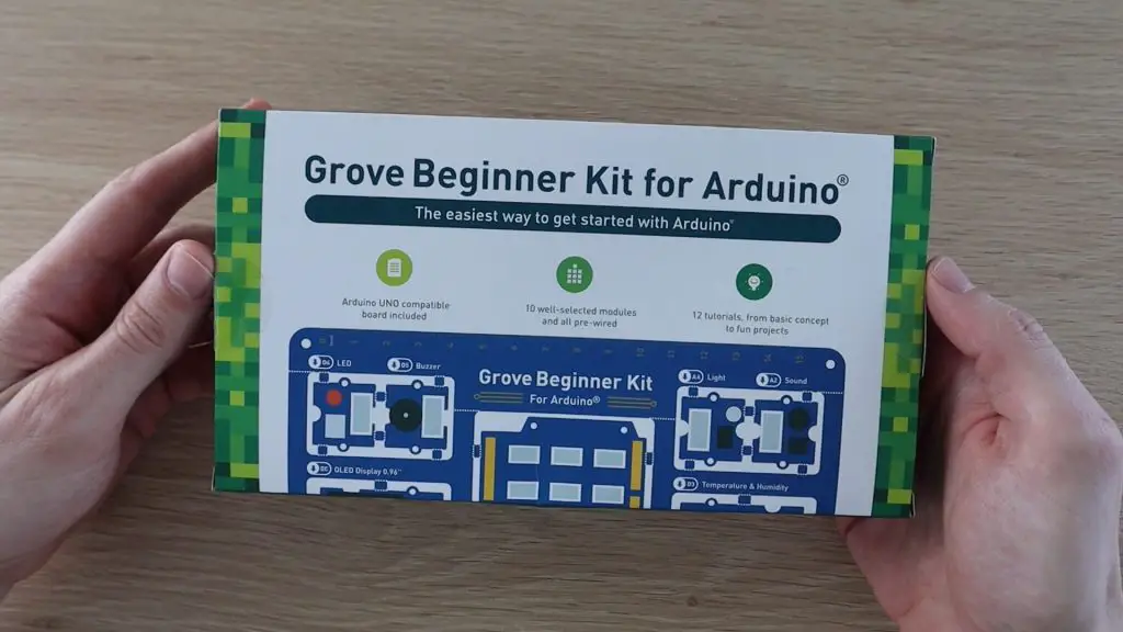
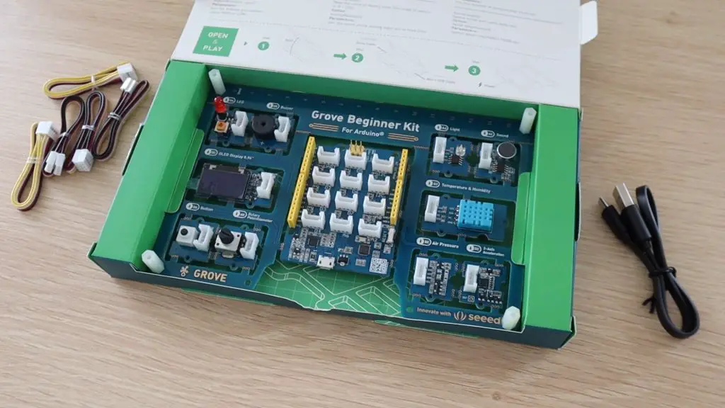
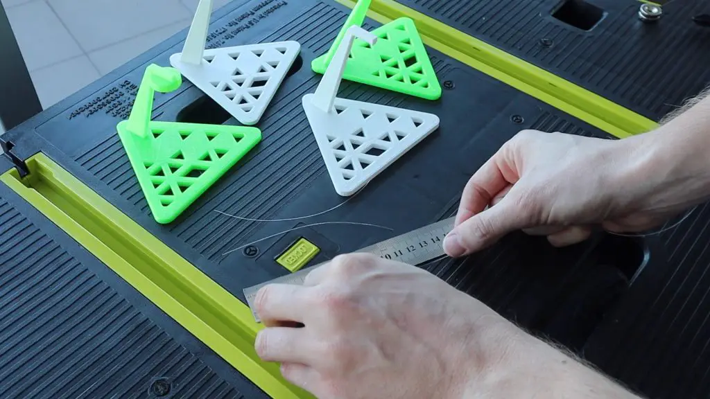
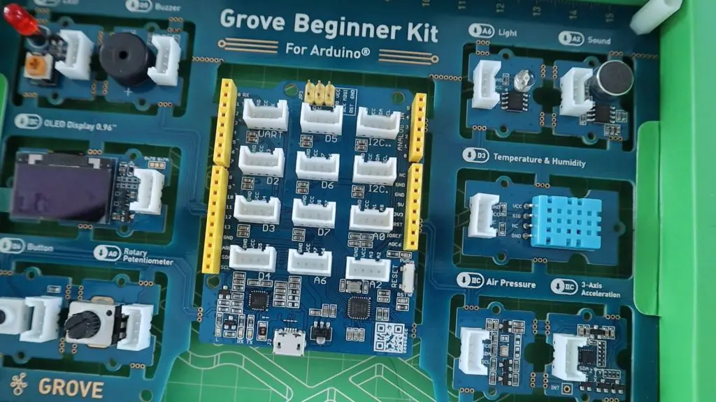
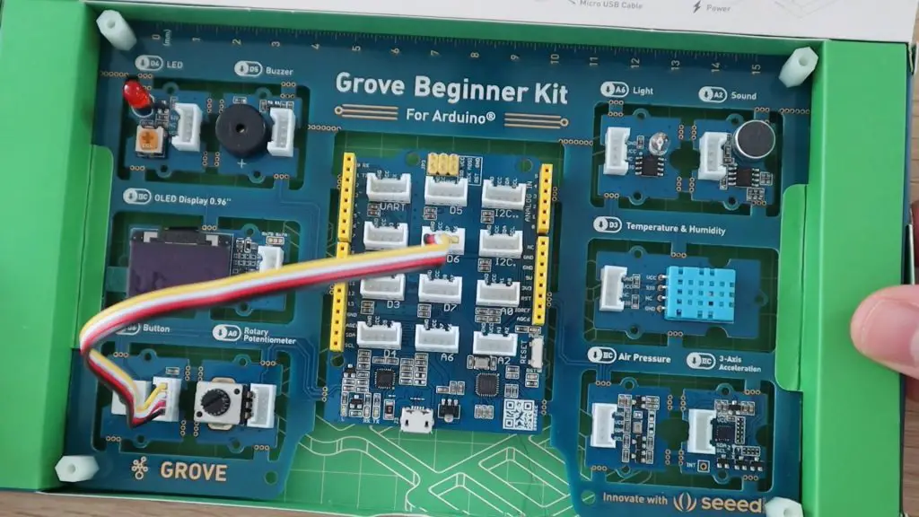
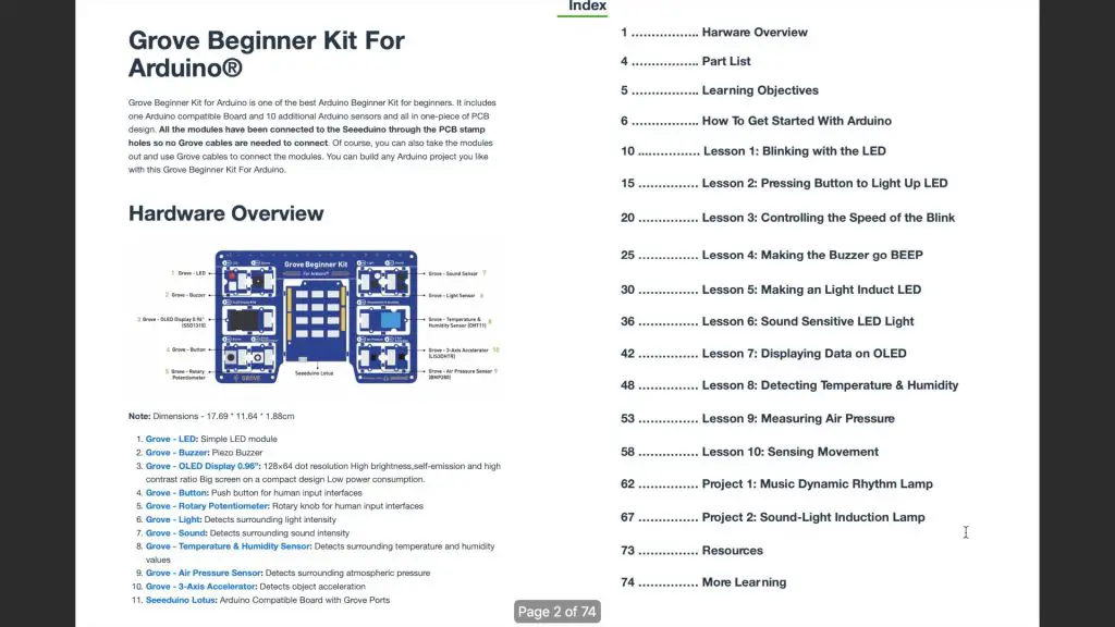
The kit comes in the form of a single PCB which includes a Seeduino in the middle, which is essentially an Arduino Uno clone that has been adapted to include 12 Grove connectors, surrounded by 10 Grove modules.
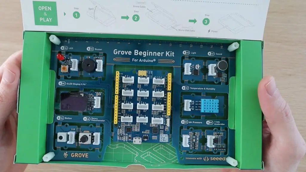
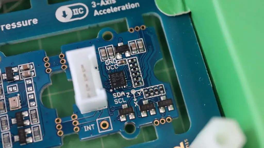
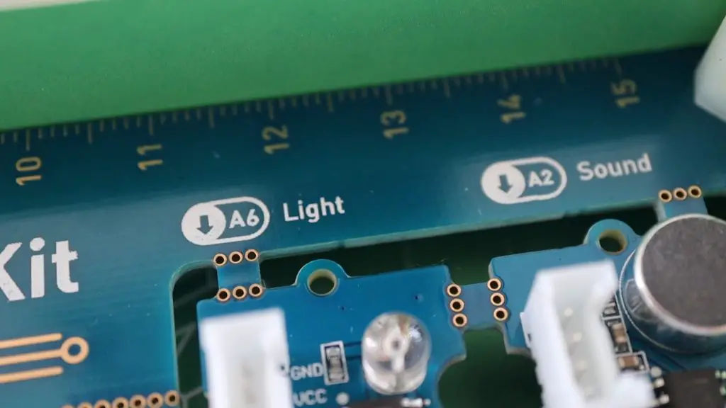
Briefly looking at the included modules, you get an LED, a buzzer, an OLED display module, a pushbutton, a rotary potentiometer, a light sensor, a microphone or sound sensor, a temperature and humidity sensor, an air pressure sensor and finally a 3-axis accelerometer. All of these modules are already connected to the Arduino, so you don’t need to worry about doing any wiring.
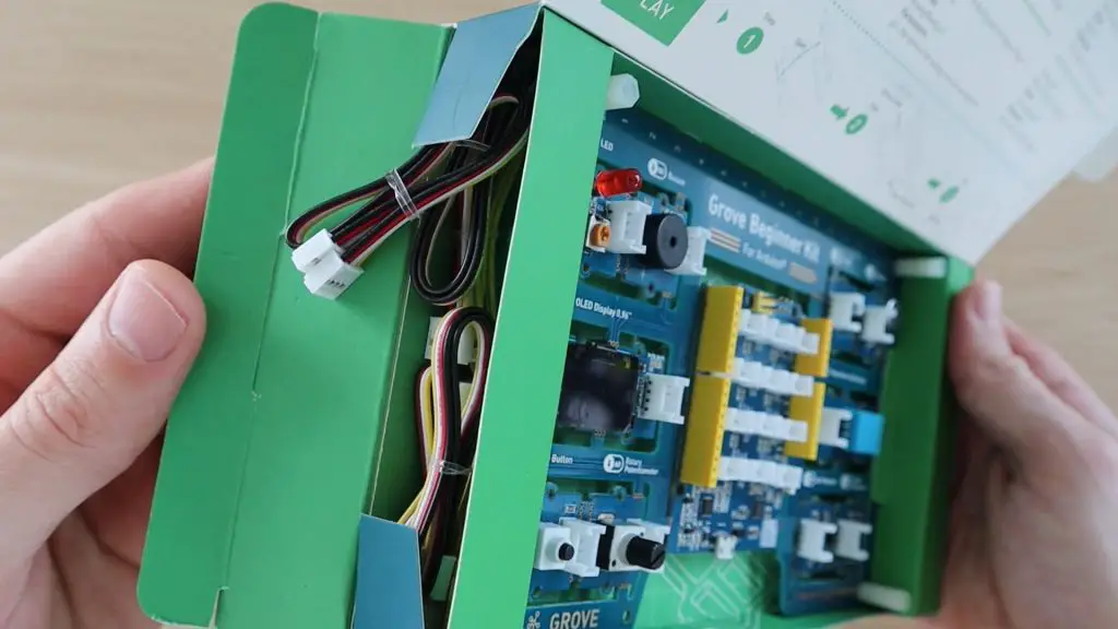
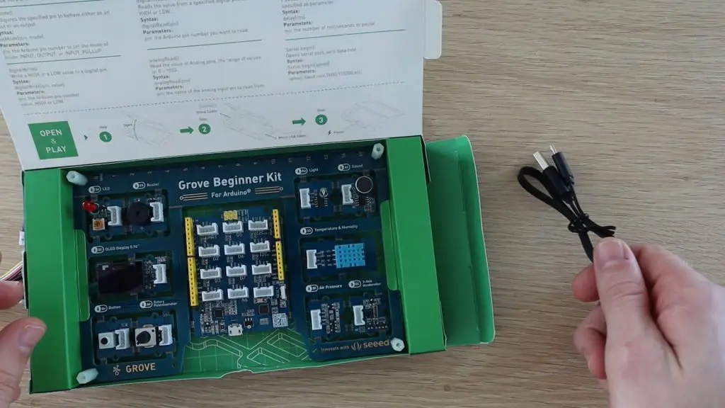
The kit comes with 6 included Grove cables to connect the Grove modules once removed and a micro USB cable to program the Arduino. All of the cables are neatly packed into the sides of the box.
Grove modules are essentially a rapid prototyping platform, with each module designed to be a plug and play device which is connected to the microcontroller using a four-wire Grove cable. The modules are standalone components and therefore don’t require any further electronic components to work, so you can move right on to programming.
The system has grown to over 300 modules and can be used across a number of different platforms, including Arduino, Raspberry Pi, Microbit and Beaglebone.
What makes this kit particularly easy to use is that the modules are already wired to the various power supply and IO pins on the Arduino through the PCB, so you can literally start programming it immediately.
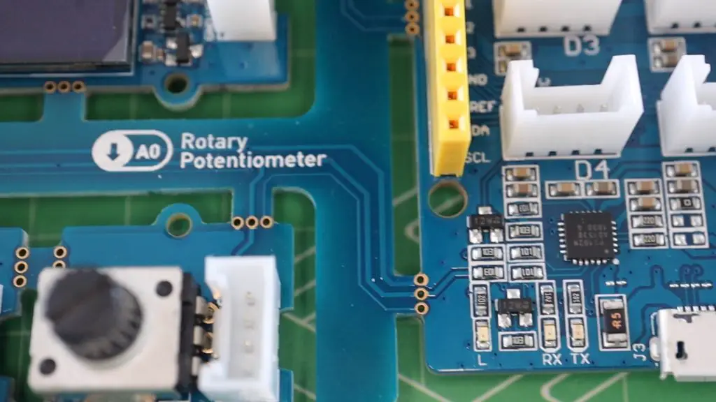
Each module is labeled with it’s associated IO port or interface and a set of example lessons guide you through using and programming each module.
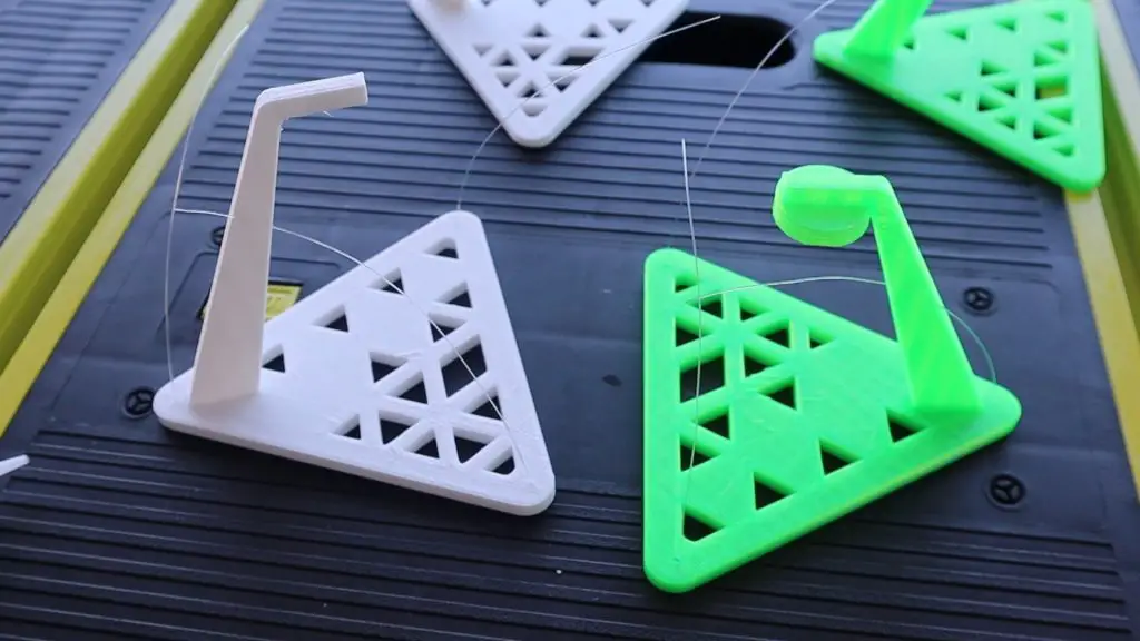
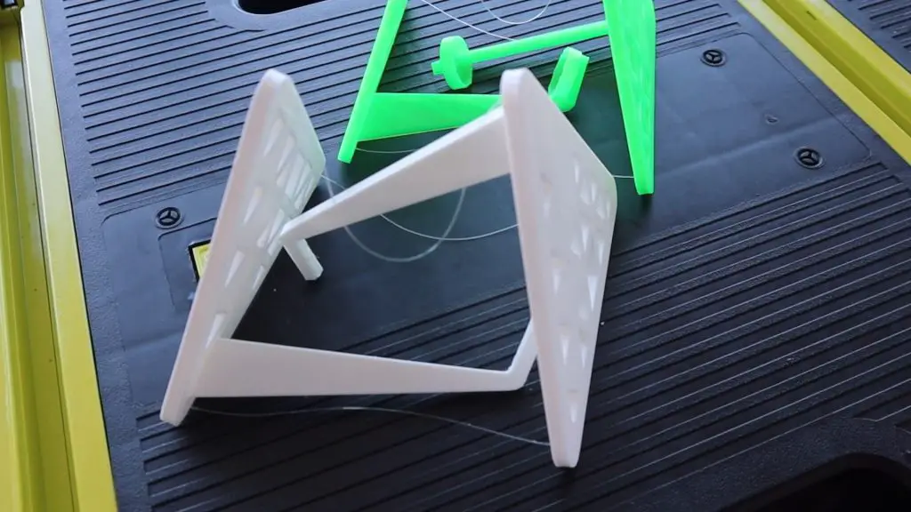
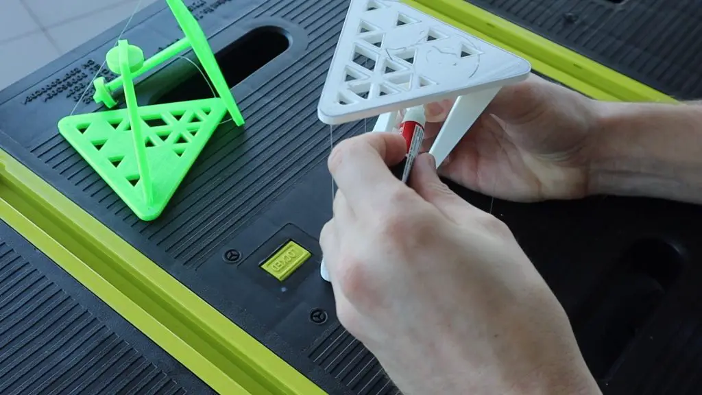
What separates this kit from other pre-wired kits, is that you can also break the Grove modules and Arduino off of the PCB and use the included grove cables to connect the modules with the PCB in order to create actual projects. So you’re not limited to using all of the components in place on the PCB. You can also buy additional Grove modules and use them with the included modules and Arduino to build more complex projects.
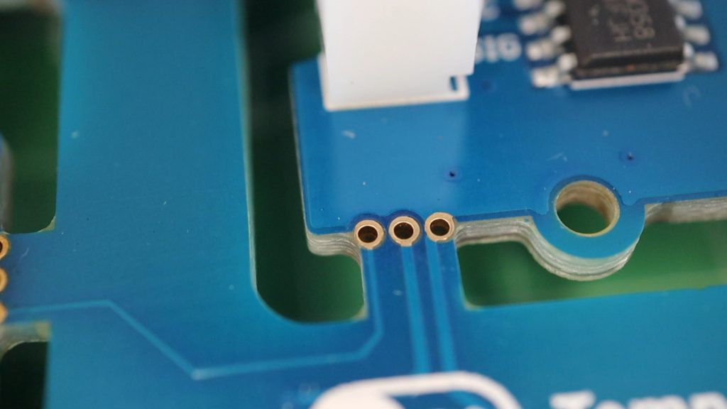
The modules and the Arduino are designed with through-hole “tabs” which make them easy to break out of the main PCB to use on their own.
The 6 included grove cables can then be used to connect the modules to the Arduino once they have been removed. They also don’t need to only be used with the IO port assigned to them in this kit. Once removed, each module can be used with any available digital, analog, or I2C Grove port, depending on the module type.
Powering It Up & Programming It
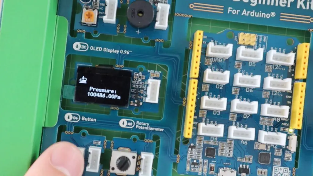
When you first plug in the included USB cable to power up the board, a demo program allows you to fiddle around with all of the sensors, using the pushbutton and potentiometer to scroll between and select different options.
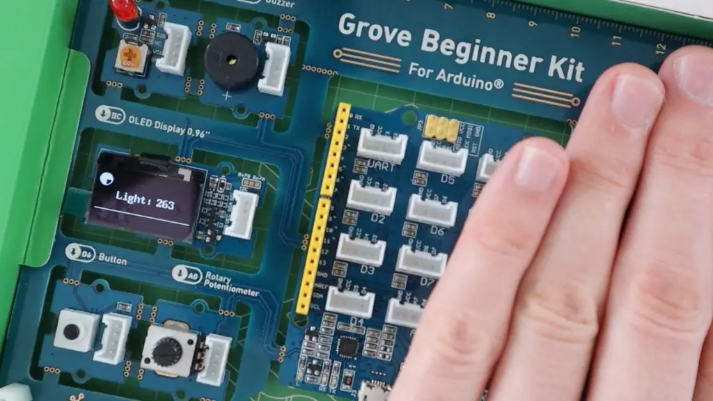
This gives you some idea of what each modules does and what it could potentially be used for.
There is a digital copy of the user manual available for download from the product page. I’d suggest downloading the last file, called all resources in one, which includes all of the required libraries and the example lessons and projects referenced in the manual. There is also some other documentation on the sensors used on the Grove modules as well as the Arduino IDE.
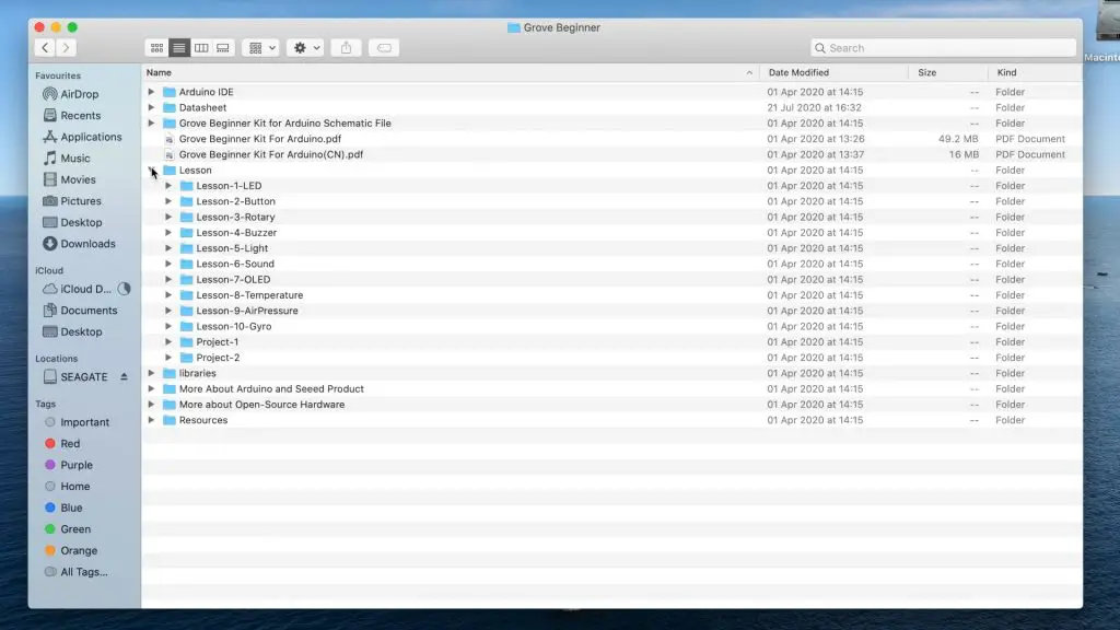
The Grove Beginner Kit manual is pretty good and explains how to install the Arduino IDE as well as how to program and use each of the included Grove modules, along with example code and explanations.
There are also two basic projects included at the end, which each make use of multiple modules and give you an idea of how the modules can be used in your own projects.
Using The Kit For Your Own Projects
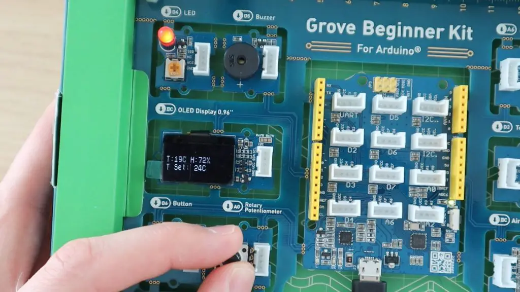
Rather than take you through one of the included projects, I’ve put together an example that makes use of the temperature and humidity sensor, the potentiometer, LED, buzzer, and OLED display. All of the elements used in the code were copied over from the example Lessons and modified slightly to work together as a single project.
The OLED display shows the current humidity and temperature, read from the DHT sensor, and the potentiometer allows you to adjust a temperature set-point. If the temperature fluctuates 5 degrees above or below the set-point then the LED will light up and if it fluctuates 10 degrees above or below the set-point then the buzzer will also sound.
//The DIY Life
//Temperature & Pressure Example
//25 July 2020

#include "DHT.h"                                                          //Import the required libraries for the sensor and OLED display
#include <Arduino.h>
#include <U8x8lib.h>

#define DHTPIN 3                                                          //DHT Sensor Pin
#define DHTTYPE DHT11                                                     //DHT 11 Temperature & Humidity Sensor
DHT dht(DHTPIN, DHTTYPE);

int potPin = A0;                                                          //Set the potentiometer pin number
int ledPin = 4;                                                           //Set the LED pin number
int buzzerPin = 5;                                                        //Set the buzzer pin number

U8X8_SSD1306_128X64_ALT0_HW_I2C u8x8(/* reset=*/ U8X8_PIN_NONE);          //Create an object to control the OLED display

int setPoint = 0;                                                         //Variable for the target temperature
int alertRange = 5;                                                       //Range above or below the target to light up the LED
int alarmRange = 10;                                                      //Range above or below the target to sound the alarm buzzer

void setup(void)
{
  pinMode(ledPin, OUTPUT);                                                //Define the component pin modes
  pinMode(potPin, INPUT);
  pinMode(buzzerPin, OUTPUT);
  dht.begin();                                                            //Connect to the DHT Sensor
  u8x8.begin();                                                           //Connect to the OLED display
  u8x8.setPowerSave(0);                                                   //Set the display modes
  u8x8.setFlipMode(1);
}

void loop(void)
{
  float temp, humi;                                                       //Create variables to store the temperature & humidity
  temp = dht.readTemperature();                                           //Read in the current temperature
  humi = dht.readHumidity();                                              //Read in the current humidity
  setPoint = map(analogRead(potPin),0,1023,0,50);                         //Read in the pot value and scale it to a temperature range of 0-50C

  if (temp >= setPoint+alertRange || temp <= setPoint-alertRange)         //If the temperature reading is above or below the alert range, turn on the LED
  {
    digitalWrite(ledPin, HIGH);
  }
  else
  {
    digitalWrite(ledPin, LOW);
  }

  if (temp >= setPoint+alarmRange || temp <= setPoint-alarmRange)         //If the temperature reading is above or below the alarm range, sound the buzzer
  {
    analogWrite(buzzerPin, 150);
  }
  else
  {
    analogWrite(buzzerPin, 0);
  }

  u8x8.setFont(u8x8_font_chroma48medium8_r);                              //Set the display font
  u8x8.setCursor(0, 33);                                                  //Set the cursor positions and display the text
  u8x8.print("T:");
  u8x8.print(int(temp));
  u8x8.print("C ");
  u8x8.print("H:");
  u8x8.print(int(humi));
  u8x8.print("%");
  u8x8.setCursor(0,50);
  u8x8.print("T Set: ");
  u8x8.print(setPoint);
  u8x8.print("C");
  u8x8.refreshDisplay();

  delay(200);                                                               //Wait 200 milliseconds between updates
}Upload the above code and try it out on your own Grove Beginner kit. Try adjusting the set-point to be 5 or 10 degrees above or below the actual measured temperature and you’ll see the LED light up and hear the buzzer sound at the different stages.
This isn’t a particularly complex project, but it shows how easy it is to get a project up and running using this kit. The code literally took ten minutes to write up by combining pieces from the included example lessons.
Conclusion
This is probably one of the best kits for new beginners as it not only makes getting started really simple, but it still includes a number of useful modules that can be separated and used in actual projects.
It’s also a fantastic design for classroom environments, where learners can get started with connecting sensors and programming the Arduino without having to worry about getting the wiring wrong and potentially destroying the components or the Arduino. You could literally have a half-hour lesson with this kit and leave having connected a couple of sensors and programmed an Arduino with little to no prior experience.
So if having to learn electronics and programming to get into Arduino sounds intimidating to you, then this kit is perfect to break the ice and get started.
All you need is one of these kits and a computer.
Let me know in the comments section if you have a favourite beginners kit and what you like about it.