Since writing up our project on how to make an Arduino Solar Tracker which makes use of a single or multiple PWM servo(s) to actuate the panel, we have had a number of requests to modify the design and code to allow for a linear actuator to be used to move a heavier load; a large panel or array of panels.
The circuit for the light detection remains the same as the original solar tracker while the servo is now replaced by a 12V DC linear actuator which is supplied by a 12V battery or power supply and controlled by two relays. Alternately, you can also drive the tracker with a stepper motor which is also controlled by the Arduino
This project is not a stand alone project but is meant to supplement our original Arduino Solar Tracker project. You will need to follow this guide in conjunction with the original guide in order to produce the linear actuator solar tracker.
What You Will Need For A Linear Actuator Solar Tracker
The parts required are as for the Arduino Solar Tracker without the PWM servo. The additional components required are:
- 12V DC Linear Actuator (Sized to suite the weight of your array) – Buy Here
- 12V DC Power Supply (Rating sufficient for your actuator) – Buy Here
- 5V DC Double Pole Relay (Current rating sufficient for your actuator) – Buy Here
- 5V DC Single Pole Relay (Current rating sufficient for your actuator) – Buy Here
How To Make The Control System
Again, the light sensor part of the control system is the same as in the Arduino Solar Tracker.
The breadboard diagram for this circuit is shown below:
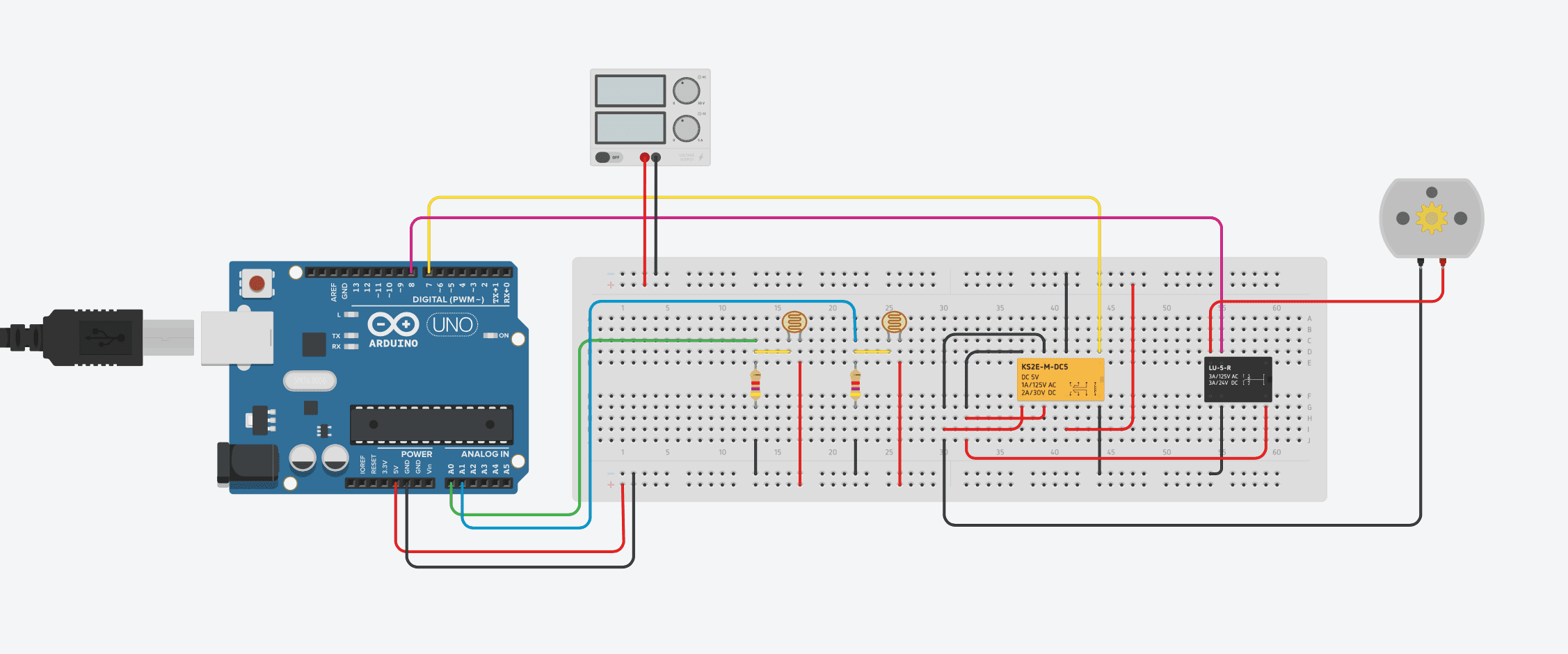
The design and code are both slightly more complex with a linear actuator as the Arduino needs to control the actuators movement duration and the direction.
A 5V DC double pole relay is used to reverse the polarity of the supply to the linear actuator. This enables the actuator to move forwards and backwards. The second 5V DC single pole relay is used to switch the movement of the actuator on and off, when activated the actuator will move. The linear actuator is represented by a DC motor in the above circuit diagram, a DC motor drives the actuating arm in your assembly.
Upload the Sketch
Now you can upload your sketch onto your Arduino, if you haven’t uploaded a sketch before then follow this guide on getting started.
//The DIY Life
//10 October 2016
//Michael Klements

int eastLDRPin = 0;  //Assign analogue pins
int westLDRPin = 1;
int reverserPin = 7;	//Assign the digital pins
int motorPin = 8;
int eastLDR = 0;   //Create variables for the east and west sensor values
int westLDR = 0;
int error = 0;
int calibration = 0;  //Calibration offset to set error to zero when both sensors receive an equal amount of light
int trackerPos = 180;

void setup()
{
  pinMode(reverserPin,OUTPUT);
  pinMode(motorPin,OUTPUT);
  digitalWrite(reverserPin,LOW);
  digitalWrite(motorPin,LOW);
}


void loop()
{
  eastLDR = calibration + analogRead(eastLDRPin);    //Read the value of each of the east and west sensors
  westLDR = analogRead(westLDRPin);
  if(eastLDR<350 && westLDR<350 && trackerPos<180)  //Check if both sensors detect very little light, night time
  {
    digitalWrite(reverserPin,LOW);
    digitalWrite(motorPin,HIGH);
    while(trackerPos<180)  //Move the tracker all the way back to face east for sunrise
    {
      trackerPos++;
      delay(1000);
    }
    digitalWrite(motorPin,LOW);
  }
  error = eastLDR - westLDR;          //Determine the difference between the two sensors.
  if(error>15&&trackerPos<180)        //If the error is positive and greater than 15 then move the tracker in the east direction
  {
    digitalWrite(reverserPin,LOW);	//Change motor direction to east
    digitalWrite(motorPin,HIGH); 	//Move the tracker to the east
    trackerPos++;
    delay(1000);
    digitalWrite(motorPin,LOW);
  }
  else if(error<-15&&trackerPos>0)  //If the error is negative and less than -15 then move the tracker in the west direction
  {
    digitalWrite(reverserPin,HIGH);	//Change motor direction to west
    digitalWrite(motorPin,HIGH); 	//Move the tracker to the west
    trackerPos--;
   	delay(1000);
    digitalWrite(motorPin,LOW);
  }
  delay(1000);
}
Here is the link to download the Solar Tracker Linear Actuator code.
The calibration of the sensor error, the tracker stand and the tracker in operation details and videos can also be found on our Arduino Solar Tracker project.
I am confused concerning the Tracker Position. Isn’t the Tracker Position redundant in this sketch since there is no Tracker Position pin or any other reference to identify the tracker position?
Hi Albert,
I assume that you are referring to the trackerPos variable? This variable is just used to provide travel limits for the actuator. The actuator in the example doesn’t provide any position feedback and we don’t have any limit switches so we rely on a time based interval to determine how far the actuator has driven. This way we can define limits for the starting position 0, and ending position 180, of the tracker.
Thank you for the reply. So there would be no harm with removing any reference to TrackerPos? In my instance, the power supply involved, a 24vdc unit, is controlled by a timer. The power supply will direct 24vdc to the actuator and 12vdc to the actuator relays and the Arduino unit. The Arduino unit will send the control signals to the 12vdc relays via 5vdc relays. The timer will turn the power pack on for five minutes four or five times a day.
I have set this up as I had mentioned and it is working great. I only had to change the values for calibration to -10 and the value for (eastLDR<450 && westLDR<450) to get it to work properly. I also changed the delay times so as not to burn up the actuator motor as rapid on off will do that. Thanks again for a great project.
Thanks Diy Life,Michael Klements on an excellent project.
I’m an old electrician new to this environment and trying to learn,I have this set up as a bench test and it works perfectly,but when the time comes to put it in use I’ll need to drive a larger DC Motor, I have been trying to incorporate a single VNH2SP30 Motor shield and include PWM speed control,but I’m not having a lot of success,any hints or help much appreciated.
Regards,JohnV
Hi John,
Good luck with your project, it sounds great! Have a look at this Tutorial on using a VNH2SP30 shield, it takes you through it step by step – http://www.instructables.com/id/Monster-Motor-Shield-VNH2SP30/
Using this shield should make your motor quite easy to control, you just need to make sure everything is wired correctly and then learn the programming controls.
Thanks for the reply that site looks good,
I haven’t got to implementing it yet, but I have discovered a problem with the original circuit that I missed previously.
When the light value falls below 350 [night time] the code locks up and does not return to the east requires reset to continue but this also resets tracker count to 180 ?
Again any help much appreciated.
JohnV
Hi JohnV, I had the same problem, was driving me nuts, see my comments above. After changing the values to >450 instead of >350, it works like a charm. I’m using a 24v 5amp 24 inch actuator to raise my panels up on one end to face east.
Hi Albert,
Thanks for the feedback. I should have put a note in the post regarding calibration and setup of the limits.
Hi John,
As Albert has said below, you may need to adjust the light value limits. I would suggest running the system with the Serial monitor open on your PC and sending the measurements from the LDRs to the monitor. The measured values from the LDRs depend on the components, the wire resistance and distance from the Arduino etc, they are very sensitive. So it may be the case that your measured light level is not dropping to below 350 and triggering the return to East function. Once you have these values then you’ll be able to properly set the night time limit and the error margin before the actuator is triggered. Thanks for the feedback!
Thanks a lot Diy Life and Albert.
Its great to receive help so rapidly,I would have been struggling for days.
Albert your project sounds interesting.
All is good now
hlo sir
i am using 9v servo motor is it sufficient for the panel to rotate
Hi Akash,
The voltage of your servo motor is fairly unrelated to whether it can rotate a panel. What size is the panel? How is it mounted? How much torque can the servo motor produce? If you’re not sure then you should mount your servo motor onto a small stand and do some tests to figure out how much load it can drive.
Hi,
thanks for sharing your tutor. In the search, I also found the article https://12vactuators.com/solar-tracker-with-linear-actuator/. Seems it also about solar tracker and now I’m thinking on which of these two projects is more reliable in terms of time. Will be grateful for your opinion.
Hi Adam,
The two projects are essentially the same hardware both based on Arduino controllers and a linear actuator, the software is written a bit differently but they should take the same amount of time to build.
Why does it idle with polarity switch relay on? This draws about 150ma vs 10 ma with relay off. That will suck the juice out of the battery in a day.
You didn’t have the adjustment description and that was critical to get this to work. I spent lot of times scratching my head to figure that part and still not working quite right with tracking, reset to E at night and polarity switch relay turn on in idle!
I build the linear actuator and using your Arduino code to track so this project is truly diy. No ready to buy slap on parts!
I don’t do toy tracker. I do real size 60 to 72 cells panel for real use. I have 12 of these I want to turn them all with tracker.
That is if I can get one to work correctly first.
Thank you for showing and sharing.
Hi Tom,
Thanks for your feedback. It sounds like you’ve built quite a nice sized system!
I agree with you, it would be best to switch the relay off after the movement has been completed as leaving it on just wastes energy. This would just mean including a line of code around line 55 which turns the reverse relay back off. It wouldn’t “suck the juice out of a battery in a day” though as this relay would only be energized for a maximum of 8-10 hours a day during the sunshine hours. When the sun sets, the relay de-energises to move the panel back to face the sunrise and it stays this way until the next days movement. Even being energized for 10 hours would only draw 1.5Ah from the battery, which from a 100 – 200Ah battery is fairly insignificant although wasteful.
You have misunderstood me on battery. The 200AH battery is my solar storage battery NOT the battery for the Arduino and relays. That i use a small 12V 5AH and after 1 week struggling this is what i have so far.
1/ The relay board will chatter not engage because battery is low on juice due to many factors. Solution is to use big car battery for now until i have all working then i deal with it
2/ I finally got it to track after changing some codes (change the reverse to high, light to 450)
3/ It would not rotate back to East when night falls
4/ Build the sensor correctly and make it adjustable
5/ This thing is not stable and works erratically (that is sometimes it works sometimes it doesn’t, drive me nut!)
So far it is working driving 2 full sizes panels tracking the sun, it does not reset to East at night however.
Once i have the reset figure out I will build one more actuator and gang all 6 panels together with two actuators driving all 6 panels and repeat the same for the other 6 panels. Of course i have to add more codes for the second set of LDR and actuators.
Yep that is one nice tracking one axis system but man it sure is a lot of work. Oh i will eventually convert to power MOSFET driver and get rid off the relays too.
Can you explain how the time base tracking for the East reset at night work? That is the part i do not understand of the code. Without understanding it is a struggle and time wasting with code trying to figure out how to make it work.
Hi Tom,
Thanks for the clarification. Is there any reason why you use an additional battery instead of the storage battery to power your Arduino? How and when do you charge this battery then?
The reset to East is not time based, it is based on a light level threshold from the sensor. When the ambient light drops below a certain level, signalling night time, then the tracker runs the actuator for a period of time such that it returns to the East position. You could do this with limit switches on each end as well.
This thing is driving me nut but i am not giving up. I still don’t have it working consistently for tracking and reset to East is not working at all.
I use a separate 12V battery because my storage battery is in the house too long of a wire to run. I use a small solar panel to keep it charge up.
The Arduino code has light levels and position dectection. So far and for weeks now working with this it never resets to E. at night.
This position tracking by counting from 0 to 180 is not clear at all. I am thinking of remove that code and just use the limit switch.
Hi Tom Ho, you are right to think the tracker position is useless. In my code I deleted all mention of it and depend entirely on the limit switches. One thing you have to take into account is how dark does it get where your sensors are mounted at night? If there are night lights close by, they may be causing the controller to think it’s still daylight. that depends on what you have the reverse light setting at. I found that when it was foggy in the mornings, the light from the street lights wouldn’t allow the tracker to reset to the east. Changing that setting to 450, as you have, fixed it. You may have to increase that number even more to get it to work. Also remember that many actuators have duty cycles and could burn up if they are operated without the proper amount of rest. I hope this helps.
I had it tracked to an acceptable level yesterday. Night felt then the thing started to oscillate NOT reset to East. I changed to 550 nothing!
Is there anything else i can do?
Do you ever have the reset to work on full size panels?
Two things on your reply:
1/ foggy in the morning? why does that matter when the E. reset is only done at night to get it ready for the next day?
2/ actuator burns up; NOT apply as i build my own linear actuator; as a matter of fact multiple times it reached the end of the shaft could not turn any more and stuck there grinding away until i found out still did not burn it up, another instance it felt out of the screw shaft and just kept turning still did not burn up.
Main reasons are :
a/ the photoresistor value in the code
b/ no limit switch for safety cut off
I have came to the point to have to put in limit switch for safety cut off and able to reset to East at night. Your existing code does not work!
Hi Tom Ho, My system is different from that published in DIY. I only used their code as a starting point to learn how to make something like this work. A lot of trial and error. I use a 24 vdc power supply off of 120vac to operate the sensor and actuator, 12vdc to the sensor and 24vdc to the actuator. To save on the life of the cooling fan in the power supply, I use a timer to turn the system on usually four times a day. The first time is at 5:15 AM and at that time the panels will reset to the East, in my case raise since my four panel array is hinged on the top and the acatuator lifts from about mid panels. The timer is set to stay on for 5 minutes. The other times it comes on, around 9 AM, 11 AM, 1 PM and 3 PM allows the panels to reset to the sun position until they are completely in the down position again. As I mentioned, I rely on the actuator built in limit switches to shut down the motor once the actuator has moved to it’s extreme position. I mentioned the duty cycle because that was a warning that came with the actuator I purchased. The number of panels you are controlling should be irrelevant since the controller should work by itself. I can only describe to you what I have found to help me solve my problems. The only thing I could recommend would be to increase the delay time between the next movement and investigate how to use the Serial Monitor to show you the actual sensor values being produced, something I myself need to learn. I currently have the delay within the loop set at 10000, that keeps the actuator running for ten seconds, and 5000 at the end of the loop, that causes a five second delay before the actuator runs again to drive the panels in the desired direction.
Not sure who this is Albert or the original author as it shows anonymous.
The position counter coding sucks. Whoever came up with that wrote codes but did not test it. I don’t know about you but whenever i build something it never works the first time, NEVER!
Go read the long reply i sent to Albert. I got rid off the position counter code, change all relays to home built H bridge with opto coupler interface and drastically redo the main sketch. All works beautifully now. All except for reset to E but that is coding NOT hardware issue. I am not proficient yet to figure out what i want it to do on reset to East in multiple stages and slow down at the last stage but i will eventually figure it out.
If you are good at coding Arduino i sure can use that help. In return i will show you how to go all solid state the drivers portion and get rid off the old fashion click clack noisy relays (expensive too).
You can build the h bridge for free if you have no good power tool lithium packs around. I have ton of them as i fix lithium battery (yes you can fix them along with lead acid battery).
Hi Tom Ho. I mentioned in my previous comments that I use a timer. My panels do not raise back up to face the west until morning. I mentioned the duty cycle because that was a warning that came with the actuator I purchased. Oscillating could be caused by an insufficient amount of delay at the end of the loop. I use an internal delay of 10000, keeps the actuator running for 10 seconds, and an end of loop delay of 5000, causes a 5 second delay before the actuator runs again in the desired direction. if you are still having problems with the controller resetting to the east at night, I might suggest you investigate using the Serial Monitor to identify the sensors’ actual output values which should enable you to correctly set the east reset value. I need to investigate that myself.
Albert,
After many trials and errors and tribulations I am closed to what i want it to do. The original sketch is for toy play and frankly it will never work with one major flaw – the internal position counter. That was my biggest headache and time waster.
I got rid off the position counter, install end limit switches, eliminate all relays, drastically redo the sketch. End result way way way better than the original toy sketch. I do not do toy tracker. I do a real thing total of 12 full sizes 60-72 cells panels. Sure hell complicated and time consuming. After months of tribulation I am closed to finishing.
What i did was rewrite the sketch, build and use all solid state power mosfet H bridge along with opti coupler interfaces to Arduino. In that painful process i damaged multiple Arduino mainly before doing the opti coupler interface. For every damage it was a cussing time to buy another one and waited for it to arrive to try again.
I had too many problems with relays also as burned contact, click clack noise. Enough was enough i spent weeks building the h bridge power mosfet NOT 1 but 7 as i have 6 actuators to use and one for spare. Now i can enjoy the fruit of my labor as they worked beautifully now. Best part i did not buy anything as i recycle parts from bad lithium packs. Yep from bad power tool lithium packs. I am an expert on lithium and lead acid batteries repair and construction. I had and have and will continue build up my solar power storage lithium packs. I had built 8 already. Each one is 200 AH.
Now I need your help on this only thing left. Reset to E. for next day. Include is the sketch and i can’t get it to do what i want it to do. What i want it to do is:
a/ move E. at end of day for 8 seconds one time then delay multiple minutes
b/ move E. again for 8 seconds second time then delay multiple minutes
c/ move E. again for 80ms on and keep doing it until it hits the limit switch (going too fast it blows right through the switch)
What it does:
moving as sketch dictates but it does not do a while loop; it just loop back to the fast speed of 8 second.
I am not good at coding yet to have figured it out. Can you assist?
This is the only thing left. Everything else works great from tracking to stopping at end limit both East and West.
P.s: For anyone attempting to do the solar tracker, i can’t emphasize enough the importance of using sketch of LDR reading. Until you know what the LDR’s are getting it is pointless and cussing as the darn thing not working the way you expect it. Trust me I had been through hell until i had written m y own sketch of getting the LDR’s reading. Once i know what those numbers are the rest is a piece of cake to know for sure if the main sketch is working or not.
My methodology is divide and conquer in fixing the sketch. /* xxxxxxx*/ is your best friend. Ask me if you don’t understand what i am talking about.
Let this be a warning to those that want to do the solar tracker from me as i did it to save you some grieves.
Build or slap together purchase is easy. Getting it to work is something else. Now this applies more to the worst case because i build everything from actuators to the electronic drivers. I doubt that the majority will do this way. Many if not most people just buy ready to use, slap and adapt to make it work.
I opted for the more challenge, much more difficult routes to build a real practical solar trackers NOT a toy one likes i have seen all over the web.
No wonder why because it is hard as hell and expensive to do the real thing!!!!!
Could you post your code? I’m doing a similar project and I’m having trouble controlling the motor with the relays. I want it to rotate slowly to follow the sun but it rotates pretty fast and I’m not sure if it’s reading my LDRs correctly.
I can’t copy and paste part of my own sketch to get your assistance. Can we do p.m?
Hi Tom Ho, Glad to hear you have your system working. I’m not too sure how we can PM but that would be fine with me. I can give you an email address, the same I use on this site, alynur2@yahoo.com. Looking forward to hearing from you.
Hello, how do I get it to focus on 1 light. My panel will just move to the light its tracking and then back and forth a small amount. In the same light, one LDR reads 1174 Ohms and the other 1093, doesn’t this mean I change my error to 81 and it should be focus? Help.
Thanks,
James
Hi James. I am not really sure what you are asking. Does the panel only move a small amount or is it erratically moving? Display the readings from your analogue inputs to your Arduino IDE Serial Monitor, they should be values between 0 and 1023. The difference between the two with equal light on both LDRs is what you should change your error to.
There is no such thing as focus on 1 LDR. What you want is equal amount of light thus equal amount of value if you use the ldr value sketch that i mentioned on here with Albert. For me easiest, simplest, best is to use the ldr value sketch and a simple spread sheet to know exactly what i am getting with a given light. Once i know that it is simply a matter of checking to see if code is working as written. Use /*xxxxxxxx*/ as method of divide and conquer to check for coding on sketch.
Simple, effective no guessing of ldr’s reading. With this methodology i was able to get everything to work along with some hardware changes.
I hope you are not using the position counter on original sketch. That thing sucked never worked for me until i get rid off the codes.
Are you doing the real solar tracker or the toy one?
Can someone post a screenshot of the circuit design for this project? I’m unable to see it for some reason. Thanks.
Can someone post the screenshot of the circuit design for this project? I can’t see it for some reason.
Hi….
Have you sketch for dual axis actuator,
I want to try it too if there is one
thank you
bambang priyono
from Indonesia
Hi Bambang,
I’ve found it to be uneconomical to build a dual axis tracker as you get most of the benefit from just using a single axis tracker and the complexity of a second axis is not worth the extra power you are able to get out.
I would love to have a dual axis sketch. I have 30 315watt panels. 9 kw system. The difference between summer and winter angle is a lot of power being lost. Especially with a big system.
Hi Tommy,
I will have a look at putting together a dual axis tracker project and sketch. It should be fairly straight forward to duplicate parts of the code to create a dual axis version.
Hi Micheal,
We are working on a solar tracker project to implement on a 12V DC solar panel of 17,4kg.
We don’t have access to the Autodesk link with the electronic scheme, could you please re-send the link?
Thank you in advance
Julia
Hi Michael,
I try to rebuild the solar tracker.
Do you have a photo of the connected relays because I’m a beginner in arduino.
Thank you in advance
Michael
Hi Michael,
I don’t have pictures of the setup as the moment but I’m not sure that they will help as there is a very wide range of different relays available and they have very different connection setups. You essentially need to connect the double relay to reverse the positive and negative wires going to the linear actuator and the single pole relay to simply make or break the connection so that the actuator is powered or not powered.
Are you not familiar with breadboard circuits?
Hello. I made this project and managed tomake it work. I added limit switches to this setup and added those also in code. In code there are condition that it won’t do turning sequence if switch is activated. However I figured out that there should be code also to stop turning if switch are activated while turning. How can I add condition that turning stops after time delay OR if switch is activated?
Hi Tomi,
If I understand your question correctly, you are trying to get the actuator to stop immediately when a limit switch is activated. The way the code is currently written, it will only stop the next movement from starting. You could do this by including an interrupt using the limit switch contacts, but a far easier way would be to simply reduce the time of each movement to a much lower value so that each time “step” is only a small movement of the actuator. This way it doesn’t really matter if the actuator moves another 1mm or so after the limit switch is triggered. Does this make sense?
Thank you for your reply. That would be one solution for this thing. I figured out how to do this. It needed “while” command and “delay” had to be changed to calculate time in millis. Then you can add several conditions. But I didn’t do it that way. I made while command which calculates the LDR sensors difference and continues after calculation reaches limit which is added there. There is also one condition which follows that limit switch in while command.
Thanks for sharing. Happy to hear you managed to get it working!
Hi,
I’ve just undertaken this project as a very amateur Arduino enthusiast.
My aim is to make a sun lounger that can track the sun, your design seems very promising and is what I would like to use. I have made the circuit and all is in place.
I have a problem though, it seems to mainly want to go in one direction, when the LDR’s are tested they read comparable voltages, so I’m not really sure whats going on. I presume if you put your finger over one LDR then the motor should turn one way and the other LDR, then it should turn the other way. This doesn’t seem to work, only a couple of times has it actually reversed, I’m thinking it’s probably to do with the LDR spacing and separated shielding from the sun. I just wondered if you had any thoughts.
Regards
Adrian
Hi Adrian,
Without seeing your exact circuit and code, it’s difficult to try and pinpoint a problem.
You are correct in that it should move away from an ldr if you cover it with your finger. And if the calibration is out then it would likely move all the way in one direction as soon as you turn it on.
It doesn’t sound like it’s doing either from what you’ve said. This suggests that you’ve got a wiring or code problem.
Have you used the exact circuit and code as in this example or modified it?
has anyone made a working sketch with this yet? ive been tinkering with it and making some progress but, it’s just getting frustrating
Hi justin, I have a 4 panel array that lays on a sloped roof. I raise it in the morning to receive the sun. The array will lay back down as the sun crosses over to the west. I accomplished this using a slightly edited code from the original and a timer. After the original raising of the panels at 5:30AM, the timer will turn on the controller for 2 minutes every hour and a half starting at 10:30AM untill they are completely down at around 3PM. I would advise you to learn how to use the monitor so you can make the correct corrections and insure your power lead to the sensors is plugged into the 3.5v connection. Unfortunately, I am unable to share my code or sketch but basically the outputs of the controller switch on and off 5v relays which in turn allow 12v to the directional relays of the actuators. This system has been working extremely well for over 4 years now. Since linear actuators have built in shut off switches, I elliminated all mention of a position indicator and allowed for an adequate amount of delay to allow the actuator to operate 15 seconds.
hi, Michael, I am a student and I have a project about solar tracking systems and I want to know how did you program the Arduino and why did you use the Arduino for the project, and how it works. but in summary
please reply, because this is for my school project
thankyou.
Hi,
There is lots of information online on how to program Arduinos and how they work. As for why, because they’re open source and widely supported online. There are loads of active forums and repositories for Arduino projects and code. Almost any microcontroller project you can think of has been tried by someone on an Arduino, so there is a wealth of information available for you to get started.
Hi Michael,
I am doing this for a school project but having trouble with imitating the wire diagram to the actual circuit. I have bought the relays you linked. My question is the double relay output terminals are COM and NO or COM and NC ?
Hi Chris,
The double relay outputs are all used to reverse the polarity to the motor. So you’re using both the COMs as well as both NCs and NOs. If you click on the breadboard layout it’ll open a larger image which you should be able to see. Essentially the positive and negative supply is connected to the two COMs and then the two NCs and NOs are connected such that they reverse the polarity supplied to the motor when energised.
Thank you so much for the response and help! To follow, the double relay has 2 input pins – based on the diagram there is only 1 input is this correct? So the second input pin terminal is unused?
I’m not really sure what you mean by an input pin. Your relay should have 8 pins – two for the coil, two common, two normally open and two normally closed, these are all used and indicated on the diagram.
The double relay you linked above has 6 output pins and on the other side there is two choices you of input set you can place – either 4 pins input (Vcc, grnd, in1, in2) or 2 pin input (VCC and RY-VCC).
I’ve had a look at the link and it looks like the store has changed the product (unfortunately this seems to be becoming more and more common with electronics on Amazon).
The correct relay to use is something like this – https://amzn.to/3ewHBHw
It’s not two relays, it’s a single double pole and double throw relay. The module originally linked to was a relay similar to this on a single board.
You can still use a two relay board and supply the signal to both inputs, the only issue is that if one signal doesn’t make it to the relay and one turns on and the other doesn’t then you will short circuit your supply (and likely blow the relay and/or the supply).
Amazing thank you for checking I thought I was going crazy! Yes this exact problem kept happening and I could not figure out why. I appreciate your help! would this be a comparable component for the single relay? https://www.amazon.com/uxcell-TL-4100-C-12V-Electromagnetic-Power-Relay/dp/B07JH4N3CH/ref=sr_1_15?dchild=1&keywords=5V+DC+Single+Pole+Relay&qid=1619547322&sr=8-15
Yeah sorry, that’s why I wasn’t understanding what you were asking. No, the one you’ve linked to is a SPDT (single pole double throw) relay, you need a DPDT (double pole double throw) relay. Something like this – https://www.amazon.com/dp/B0879LQQBQ
Top of the day to you sir. I read this diy article; however, I am having issues incorporating the code for a dual axis solar tracker using two linear actuators, East-West and North-South. Do you have any suggestions sir ?
Hi Peter,
You should be able to duplicate most of the code for the second axis, you’ll also need to duplicate the sensors so that you’ve got a second set across the north-south axis of your panels. You’ll then just be running two control loops, one which takes the east-west sensor values and adjusts the east-west actuator and another which takes the north-south sensor values and adjusts the north-south actuator.
sorry sir, i don’t use relay but i use driver motor. is it possible to use this code?
You can use the tracking portion of the code but you’ll probably need to adjust the outputs to drive your motor or actuator.
Hi Michael,
Thinking of using you excellent work to make a single axis tracker for my 5 panels. Thing I cant get my head around does the array need to rotate or just tilt as a lot of folks seem to do?
Just wondered if you have any views or could point me in a direction for more info?
Thanks Peter