The most commonly used Arduino board, the Arduino Uno, only has 12 available digital IO pins, so you may find yourself quickly running out of available pins on larger projects or projects requiring a number of buttons or a keypad. In this tutorial we’re going to be looking at how you can set up a large number of buttons to run on a single Arduino analog input, using resistors to differentiate between buttons. With this method, you should be able to reliably connect up to 50 push buttons to a single Arduino analog input. We’ve also been able to connect a standard 4×4 keypad to a single Arduino analogue input.
To improve your understanding of this concept, we’re going to be going through the connection of a single push button to your Arduino, then the usual connection of multiple buttons to their own digital IO pins and finally multiple buttons to a single analog pin.
This project assumes you know the basics of Arduino programming, otherwise read our article on getting started with Arduino.
Here is the video guide for Method 2 below, if you don’t want to read through the guide.
What You’ll Need For This Project
- Arduino (Uno Used Here) – Buy Here
- Breadboard – Buy Here
- 5 Push Buttons (Or As Many As Required) – Buy Here
- A Selection of Resistors (1K, 2K, 3K, 5K and 10K Used For Method 1) – Buy Here
- A Selection of Resistors (220 Ohms Used For Method 2) – Buy Here
- Another Resistor With Higher Resistance Than The Highest Used Above (100K Used Here)
Connect A Single Push Button to A Digital Input Pin
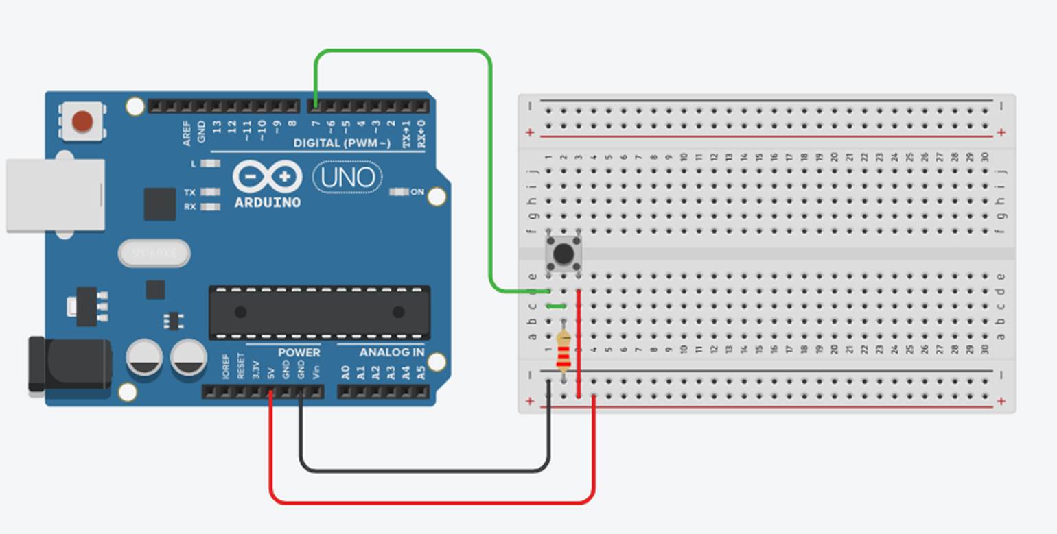
To start off, lets look at connecting a single push button to a single digital input pin, Pin 7, on your Arduino and use it to turn off the built in LED on Pin 13.
Connect your push button and 2K resistor as shown in the breadboard diagram below.
Now lets have a look at the code required to turn the LED on Pin 13 off when the button is pushed.
//Michael Klements
//The DIY Life
//17 May 2019

int ledPin = 13;    // choose the pin for the LED
int inputPin = 7;   // choose input pin 7 for the push button

void setup()
{
  pinMode(ledPin, OUTPUT);  // declare LED as output
  pinMode(inputPin, INPUT); // declare push button as input
}

void loop()
{
  int pushed = digitalRead(inputPin);  // read input value
  if (pushed == HIGH) // check if the input is HIGH
    digitalWrite(ledPin, LOW);  // turn LED OFF
  else
    digitalWrite(ledPin, HIGH);  // turn LED ON
}
As you can see from the above connection diagram and code, it is quite simple to connect a single push button and use it to drive other IO or settings in the code on your Arduino.
Connect Multiple Push Buttons To Multiple Digital IO Pins
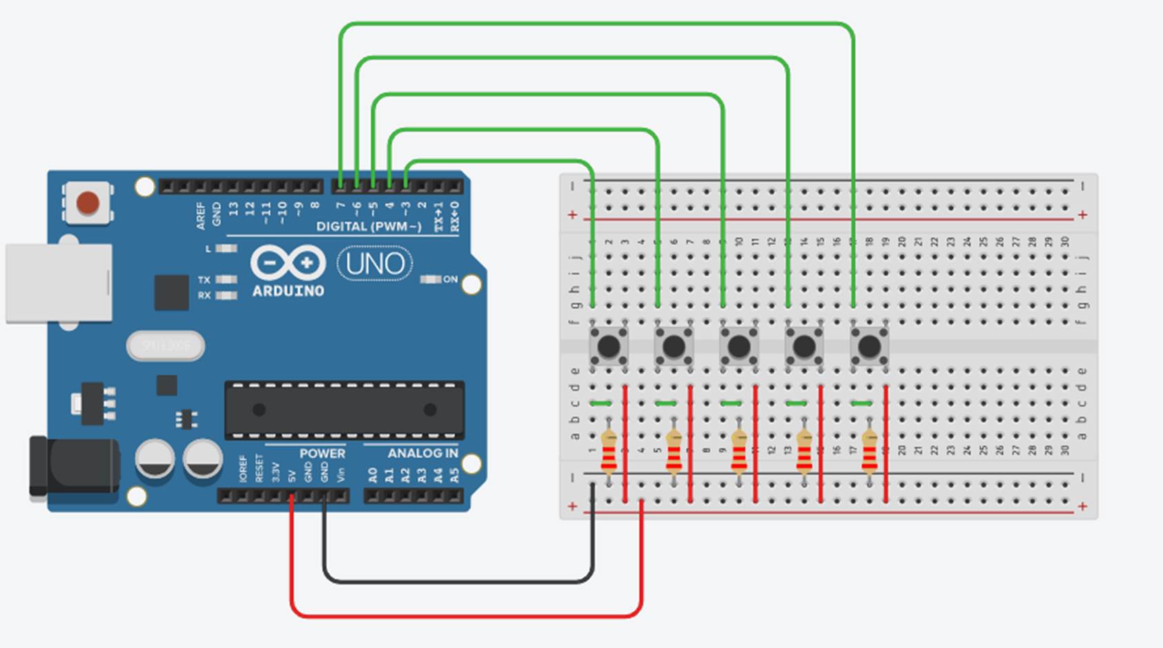
The problem comes in when you need to use multiple buttons. A 10 digit keypad for example uses 12 inputs, 10 digits from 0 to 9 and then a further two for the * and # keys. Let have a look at how we’d connect 5 push buttons using the standard digital IO method.
If you’re specifically looking to connect a 4×4 keypad to a single Arduino input, take a look at the linked guide as they are typically wired a little differently to the below example and you’ll need to make some adjustments to your circuit.
Try connecting up 5 push buttons and 5 2K resistors each connected to a separate IO pin on your Arduino as shown in the breadboard diagram below.
Let’s now have a look at the code required to turn off the LED on Pin 13 if any of the push buttons are pushed. I have created a function which runs through the input checking code to avoid code duplication, follow this link if you’d like to read up more on using functions to simplify your Arduino code and make it more efficient.
//Michael Klements
//The DIY Life
//17 May 2019

int ledPin = 13; 	 // choose the pin for the LED
int input5Pin = 7;       // define push button input pins
int input4Pin = 6;
int input3Pin = 5;
int input2Pin = 4;
int input1Pin = 3;

void setup()
{
  pinMode(ledPin, OUTPUT);   // declare LED as output
  pinMode(input5Pin, INPUT); // declare push button inputs
  pinMode(input4Pin, INPUT);
  pinMode(input3Pin, INPUT);
  pinMode(input2Pin, INPUT);
  pinMode(input1Pin, INPUT);
}

void loop()
{
  for(int i=3 ; i<=7 ; i++)
    checkPush (i);
}

void checkPush(int pinNumber)
{
  int pushed = digitalRead(pinNumber);  // read input value
  if (pushed == HIGH) // check if the input is HIGH (button released)
    digitalWrite(ledPin, LOW);  // turn LED OFF
  else
    digitalWrite(ledPin, HIGH);  // turn LED ON
}
Now, when you push any of the buttons, your LED should turn off.
Connect Multiple Push Buttons To A Single Analog Input
Now that we’ve looked at how we would typically connect up multiple buttons to multiple Arduino inputs, lets see how we can make the wiring, code and use of inputs more efficient by making use of a single analog input to drive inputs from multiple push buttons. We’ll again be using 5 push buttons in this example but you can reliably connect up to 50 push buttons to a single Arduino analog input.
Method 1
The concept used in this example is quite simple. We assign a different value resistor to each push button so that the analog input will receive a different value (between 0 and 1023) for each button, allowing us to recognise which button has been pressed.
Let’s have a look at the breadboard connection diagram.
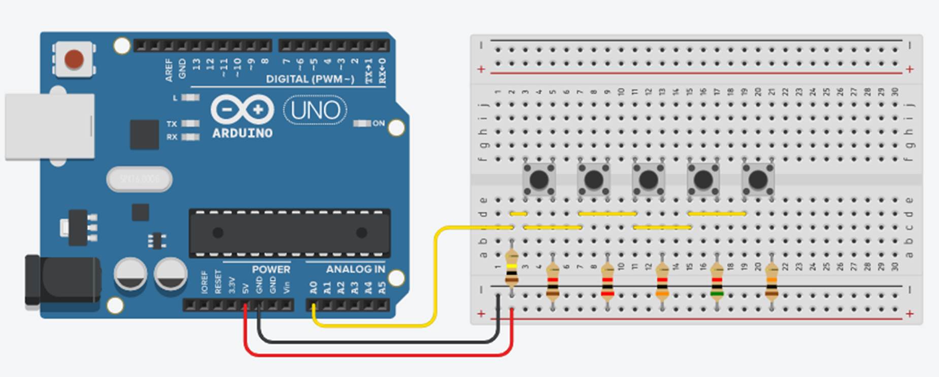
We connect a single 100K resistor between GND and the analog input, with the analog input also connected to one leg of all of the push buttons. We then connect different resistors between the 5V and the second leg of each of the push buttons. It is important that each of these resistors are different values so that you get different voltages on the analog input, enabling you to identify each button.
You can already see that the connections required to the Arduino are much simpler in this example than in the previous one.
Now lets have a look at how we write the code to differentiate between the push buttons.
//Michael Klements
//The DIY Life
//17 May 2019

int ledPin = 13; 	 // choose the pin for the LED
int buttonValue = 0;

void setup()
{
  pinMode(ledPin, OUTPUT);   // declare LED as output
}

void loop()
{
  buttonValue = analogRead(A0);  //Read in the button value
  if (buttonValue>=1009 && buttonValue<=1020)  //Switch the LED on if button is pressed
    digitalWrite(ledPin, HIGH);
  if (buttonValue>=999 && buttonValue<=1007)
    digitalWrite(ledPin, HIGH);
  if (buttonValue>=984 && buttonValue<=997)
    digitalWrite(ledPin, HIGH);
  if (buttonValue>=953 && buttonValue<=982)
    digitalWrite(ledPin, HIGH);
  if (buttonValue>=910 && buttonValue<=951)
    digitalWrite(ledPin, HIGH);
  else
    digitalWrite(ledPin, LOW);  //Switch the LED off if button is not pressed
}
You can already see that the code is much simpler using the analog input as you are not required to define and set up your IO for analog pins. The statements required to check which button is pressed are slightly more complicated than with digital IO.
Essentially your Arduino will read a value between 0 and 1023 on the analog pin and will need to compare this value to a particular range in order to identify which button has been pressed. We use a range rather than an absolute value because the analog input and resistors are very sensitive to external influences such as temperature. A value may be right on the limit between 1012 and 1013 so it will be measured as 1012 when the resistor or room temperature is cold but 1013 when it is warmer.
You will need to set up the range in your code for each push button and the values you use can be worked out in three different ways.
- Before writing your actual code, write a simple program to use the serial monitor to display the value read on the analog input for each different button press. Record these values and add a bit (5 to 20) on either side of each value to get your overall range for each button.
- Measure the voltage put on to your analog input when each button is pressed and scale this voltage to a number between 0 and 1023. For example, if you measure 4.75V on your input, 4.75 / 5 * 1023 = 972. Add a little above and below the number and your range could be 965 to 980.
- Calculate the voltage put onto your analog input by each push button using the known resistance values of your one overall resistor and each individual resistor. Map this voltage to an analog input range as done in option 2.
Obviously the greater the number of buttons you use the smaller your range for each button.
Method 2
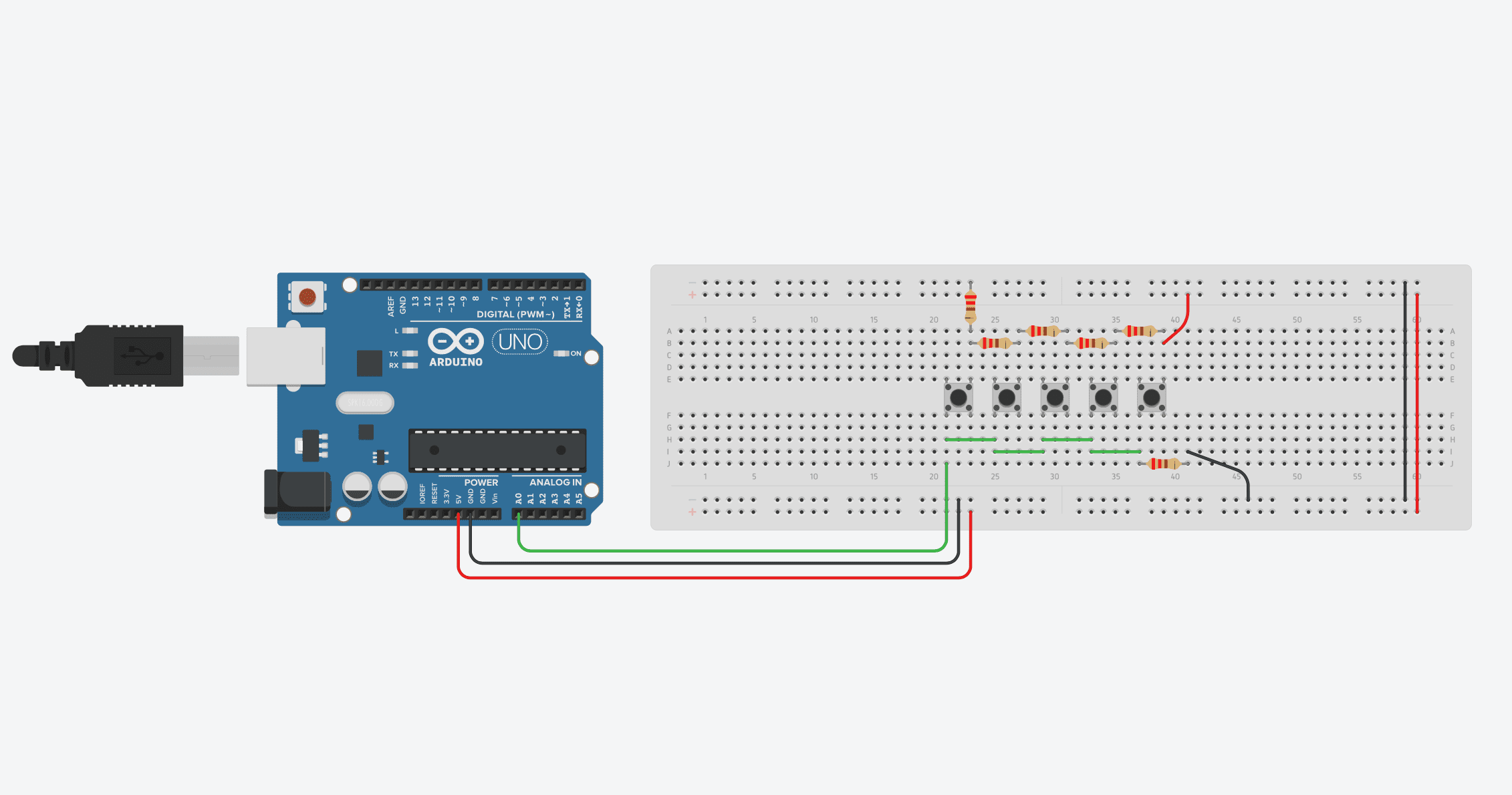
The second method is quite similar to the first, with the difference being that you can use a number of the same resistors to make up the circuit. This is useful if you have a pack of similar resistors, such as the 220 ohm ones commonly used for LEDs.
You’re going to connect these up in series to create a voltage divider, for which each pushbutton brings up another resistor in the series connection, allowing you to differentiate between them. This is the method shown in the video in the introduction, so it may be worth watching for more information.
Let’s have a look at the breadboard connection diagram.
Now lets have a look at how we write the code to differentiate between the push buttons.
//The DIY Life
//Michael Klements
//20 March 2020


int buttonPin = A0;     //Button and LED pin numbers
int ledGreen = 2;
int ledRed = 3;
int ledBlue = 4;


void setup()
{
    pinMode(ledGreen, OUTPUT);    //Define LED pins
    pinMode(ledRed, OUTPUT);
    pinMode(ledBlue, OUTPUT);
    Serial.begin(9600);           //Serial monitor used to determine limit values
}

void loop() {
  int temp = analogRead(buttonPin);   //Read the analogue input
  Serial.println(temp);               //Display the read value in the Serial monitor
  if (temp < 100)                     //Lower limit for first button - if below this limit then no button is pushed and LEDs are turned off
  {
    digitalWrite(ledGreen, LOW);
    digitalWrite(ledRed, LOW);
    digitalWrite(ledBlue, LOW);
  }
  else if (temp < 150)                //First button limit - if below this limit but above previous limit then the first button is pressed
  {
    digitalWrite(ledGreen, LOW);
    digitalWrite(ledRed, HIGH);
    digitalWrite(ledBlue, HIGH);
  }
  else if (temp < 250)                //Second button limit
  {
    digitalWrite(ledGreen, HIGH);
    digitalWrite(ledRed, HIGH);
    digitalWrite(ledBlue, LOW);
  }
  else if (temp < 350)                //Third button limit
  {
    digitalWrite(ledGreen, LOW);
    digitalWrite(ledRed, LOW);
    digitalWrite(ledBlue, HIGH);
  }
  else if (temp < 850)                //Fourth button limit
  {
    digitalWrite(ledGreen, LOW);
    digitalWrite(ledRed, HIGH);
    digitalWrite(ledBlue, LOW);
  }
  else                                //If none of the previous buttons are pressed, then the fifth button must be pressed
  {
    digitalWrite(ledGreen, HIGH);
    digitalWrite(ledRed, LOW);
    digitalWrite(ledBlue, LOW);
  }
  delay(100);                         //Delay for stability
}
You now know how to connect all of your push buttons to a single analog input and free up your IO for larger projects. I hope that you enjoyed this tutorial, let me know how it went for you in the comments section below.
Share This Tutorial
Thank you for sharing helpful information.
Can this set up only deal with one button push at a time, or can it show status for each button input if multiple states are true?
If you calculate your resistance values so that any combination of buttons being pressed at the same time does not provide the same resistance as any individual button then you can differentiate between individual and multiple buttons being pushed.
I tried to do this with only 4 buttons, but no matter what values I choose I cannot get any 2 states to be more then about 0.09V away from another one. A perfect solution would allow for a spread of about 0.33V. Is there a better way to get the minimum spread to be closer to the 0.33V?
Great solution, I wonder if you can help me based on this multi push buttons , 15 (+ 1 backward ) to make a multiple individual counter . One each counter triple 7 segment display for the counts.
Hi Avi,
You should be able to connect the 16 push buttons to the one Arduino input using the above method with 15 different resistors.
To connect a 3 digit 7 segment display to your Arduino, you’ll need to use a shift register, like the 74HC595. I’ll work on a tutorial for connecting a 7 segment display to an Arduino as there are a number of components you need to connect to get the display to work correctly.
I have problem using analog input. I use 3 buttons. and I got it working. But my third button is not grate. it Regestrating on hard around 900 but somtimes 100 and 400 and so on. and then I got all different flashes from the leds. :/ Is there a way to control 3 leds whit 3 buttons on digital input?
Hi Johan,
It sounds like you’ve got a loose connection or a faulty switch. Using this method you need to have a reliable input when the button is pushed. It can vary between say 895 and 905, but shouldn’t be fluctuating down to 100 and 400, this sounds like the switch is dropping out/intermittently making contact. There isn’t a method (that I’m aware of) to connect 3 pushbuttons to a single digital input, at a minimum (using binary), you’d need at least 2 pins.
I can use 3 input pins. My problem was that I could not use all 3 at the same time. I did try several different way and spend 2 days whit it research try and fail. The program cud only execute the button in top of defined inputs. I have solved it Real messy by go back to my Old Qbasic skills and used goto command to create loops to jump between. I Understand that’s not a god way to program but It’s doing what I want now. I have one start loop whit 3 If/else If for (, enter), the loop can jump between 6 other loops Identical. and all loops have new define of inputs. from the 6 loops they are going to exicute part of script whit goto and then back. 😀 Would be glad If you could told me what I did wrong from beginning. Sorry for my poor English. 😀
Cant post arrows seems like. 😀 (left, right, enter)
My values just rise and fall. Nothing pressed.
0
171
639
966
1023
938
539
163
0
27
331
787
1023
1023
863
406
36
0
50
385
803
1023
1023
833
368
Fluctuating values like that indicate that the analog input is “floating”. Check that you’re connected to and are reading from the correct analog input, if so then you’ve probably got a loose connection on your breadboard. The analog input is tied to ground through a resistor, so if the connections are good then its not possible to get fluctuating values.
Tried this on a Leonardo.
Running the multiple buttons on multiple inputs would not work. It just processes thru the check function too fast. Once I changed it to:
void checkPush(int pinNumber)
{
//int pushed = digitalRead(pinNumber); // read input value
while (digitalRead(pinNumber) == HIGH)
digitalWrite(ledPin, LOW); // turn LED OFF
digitalWrite(ledPin, HIGH); // turn LED ON
}
Then I got the expected behavior.
Thanks. I got it working. I think the button stems weren’t in deep enough into the breadboard
That’s great, happy you’ve managed to get it working!
One more question. Using 220 resistors for 4 buttons. How are you calculating the “if” range for each button? Thanks
You’re setting up a voltage divider. So if they’re all equal resistance values then you’d expect the voltage to be divided equally across the four buttons. Because the resistors and connections are not perfect, it’s best to just display the raw analog input values on the Serial monitor and then record the value shown for each button push. You can then update the if statements to suit these values.
That’s what ai thought but when I reduce to 4 buttons. I get 0…1,3,4,5 as output. The 2’s range never happens that why I asked.
Yes, you’ll need to recalibrate the values in the if statements using the raw values from the analog input, not the button numbers. Removing a button and resistor shifts the whole divider to a new range of outputs, you need to set these up in your code before it will display the correct button values.
Ok. Got it. Thanks. I was still working off your original numbers thinking removing #5 would just leave the original 4.
Awesome tutorial.
Is it possible to incorporate LED illuminated bush buttons to go on when a button is pushed? I imagine in this case each LED will need a separate digital pin?
I’ve been planning a project with a lot of buttons and thought about using LED buttons as well. I’ve come to the conclusion that, yes, each LED would require its own digital PIN. For my project that quickly becomes too complicated and expensive.
Have a look at the PCA9685 drivers, you can easily drive 16 LEDs with each of them and they’re really cheap.
When using multiple buttons on a analog input and allowing debounce if i hold the button on it loops through getting on each time through. Any simple code to only get an on following an off. Thanks
You could just add a boolean variable (true or false) which is changed to either true or false depending on the previous state and then have an LED update routine after the button press which sets the LED to whatever the variable state is. Does this make sense?
About multiple analog buttons.
You have 2 readings like buttonValue>=265 on button 1 and buttonValue>=685 on button 2.
If you push thise 2 buttons at the same time, can you in the program add those 2 values together for 1 command to 1 digital pin ?
Thanks.
You could do what you’re suggesting, but not by just adding the two values. Depending on which layout you’ve used, you’d need to work out the equivalent resistance and resulting voltage. The easiest would be to just press both of them with the analogue input being displayed on your serial monitor and see what you get. You’d then use this value as a new “combination button”.
Hi Calling from New Zealand. I have a stand alone device for model trains which has a 4 key keypad with leads to its controller. Each entry needs 1 to 3 keypresses in specific sequence
Will run a parallel cable to uno. Can you guide me or refer to document to have 5 x inputs to uno that is say 5 touch buttons and when 1 is pressed it will send a sequence to the parallel 4 x keypad
The keypad presumably needs only a momentary contact. Help is the operative word I am aged challenged 77 . swchuck at Gmail dot com thanks
..
I
Hi Charles,
What you are describing sounds like it would be possible to get an Arduino to do. Your application is likely far too specific to find a reference document that takes 5 inputs and sends a sequence to a 4 x keypad. Have a look at reference guides online for digital pushbutton inputs and then try getting the digital outputs to respond in sequence to your inputs. To trigger the keypad, you might be able to use the digital IO directly or a device like an optocoupler to “switch” them.