A 4×4 keypad is a really useful Arduino project component, particularly for security access projects or projects requiring code inputs. One of the problems with using the keypad however, is that you’re going to be using up 8 of your Arduino inputs just to read all of the buttons. This is obviously more efficient than connecting the 16 buttons individually but it’s still using up the majority of your Arduino’s IO. If you’re using one of the smaller Arduino boards such as the Uno or Nano, you’re not going to be able to connect something like an LCD display, TFT display or Ethernet shield to it as well, making it difficult to display the code which has been input and really limiting the functionality you could bring to your project. So, in this guide we’rd going to be looking at a way in which you can connect your entire 4×4 keypad to a single Arduino input and still read each button individually.
This project assumes that you know the basics of Arduino programming, otherwise follow our guide on getting started with Arduino.
Here’s a video guide, otherwise read on for the step by step instructions:
What You’ll Need For This Project
- Arduino (Uno Used Here) – Buy Here
- 4×4 Keypad – Buy Here
- LCD Display – Buy Here
- or LCD Shield – Buy Here
- Resistor Set (10 Different Value Resistors Required) – Buy Here
- LCD Contrast Potentiometer – Buy Here
- Breadboard – Buy Here
- Jumper Wires – Buy Here
How To Connect Your 4×4 Keypad To A Single Arduino Input
When working on Arduino projects, people often overlook the 6 analogue inputs and start working with the digital IO, especially if they’re not using “measurement” sensors in their project. The analogue inputs can actually be quite powerful and versatile and although they require a bit more code, they can be effectively used to free up some of your digital IO.
This project draws upon a concept used in a previous project, connecting multiple push buttons to a single Arduino input, it is however a little more complex due to the way the keypad is internally wired. There isn’t a common ground and 16 outputs, one connected to each button. Instead, the buttons are wired into a grid matrix in rows and columns and you’re given a connection to each row and each column in order to identify which button is being pressed.
The overall concept is to connect a different set of resistors to each button so that you generate a different voltage on the analogue input for each button, thereby enabling your Arduino to identify which button is being pressed without actually having to connect each button individually to your Arduino and clog up your IO.
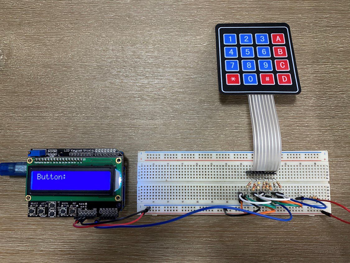
Connecting Your 4×4 Keypad
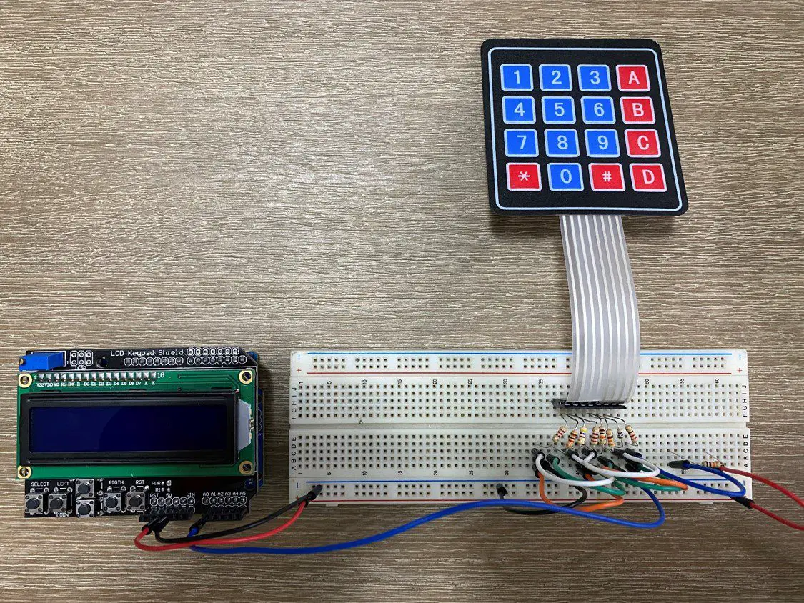
We’re going to ignore the LCD connections in this project and assume that you know how to connect an LCD display to your Arduino, if you don’t, follow the link and we’ll show you how. The LCD display in this project is just used to display which button is pressed and demonstrate than it is possible to connect a keypad and LCD display to your Arduino and still have 8 free digital IO pins! As I’ve done in the video, you can also make your project a bit easier by using an LCD Shield, which has the potentiometer, resistor and LCD connections all done for you already.
What we are going to be doing is turning the keypad into a selectable voltage divider circuit, with each button selecting a different divider configuration, resulting in a different voltage being measured by your Arduino, enabling it to identify which button is being pushed.
The voltage divider circuit consists of two resistors in series, with the Arduino’s analogue input measuring the voltage at the mid-point. We have a fixed resistor in the top half of the divider, which is the 5.1K resistor shown by itself on the top right in this example, and then a selectable group of resistors which are activated in different combinations by the keypad in the bottom half of the divider.
You can use any combination of resistors you’d like to, the actual resistance isn’t that important. What is important is that each resistor is a different resistance so that the ratios between the resistors create enough of a difference in voltage for your Arduino to detect each button combination.
Lets look at the circuit:
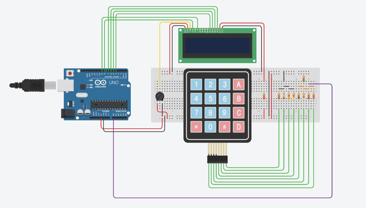
We can see that each row and each column of the keypad has a resistor connected to it, and the whole keypad and resistor circuit is connected as the “bottom” or second resistor in our voltage divider circuit. When we push a button, a connection is made between one of the resistors in the left group of four and one of the resistors in the right group of four (one row and one column) to create an overall resistance, which is unique to each button.
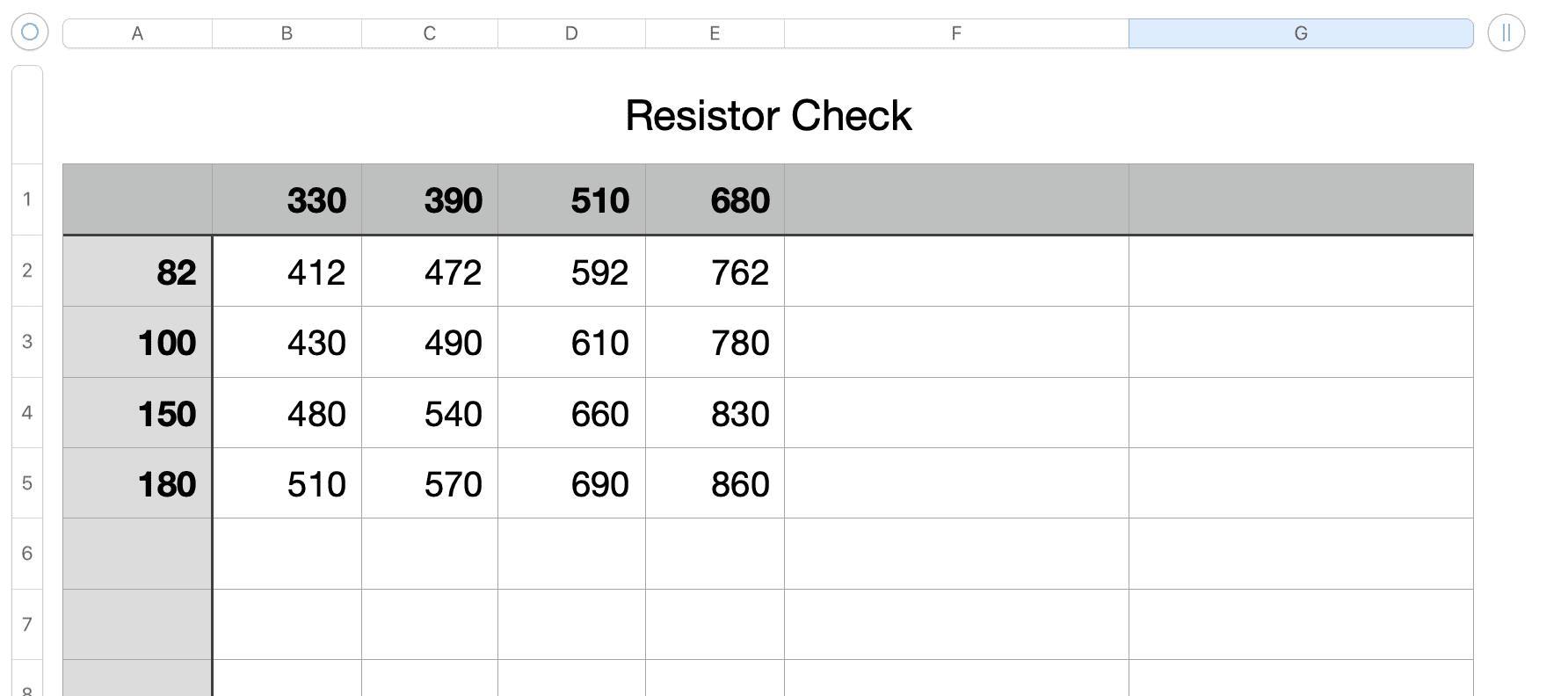
You’ll notice that all 8 of these resistors are different and it’s important that no combinations can produce the same resultant resistance. For example, an 8K and 4K resistor together in series would have the same resultant resistance as a 7K and a 5K resistor in series.
The easiest way to do this is to create a quick spreadsheet with your resistor values along the top row (4, one for each row) and the first column (4 , one for each column). Then sum up the resistance of each row and column in the cells and make sure that none of them are the same or similar (one above or below is usually too similar).
We then have a single resistor on the top right which forms the “top”or second resistor in our voltage divider circuit.
Lastly, the centre point of our voltage divider circuit is connected to one of our Arduino’s analogue inputs.
I used an LCD shield for my test setup so I don’t require the additional connections to the LCD display.
That’s the circuit complete, we can now have a look at how to code your Arduino to identify each button from the single Arduino analogue input.
The Code
Let’s now have a look at how to get your Arduino to recognise which button is being pressed in the code.
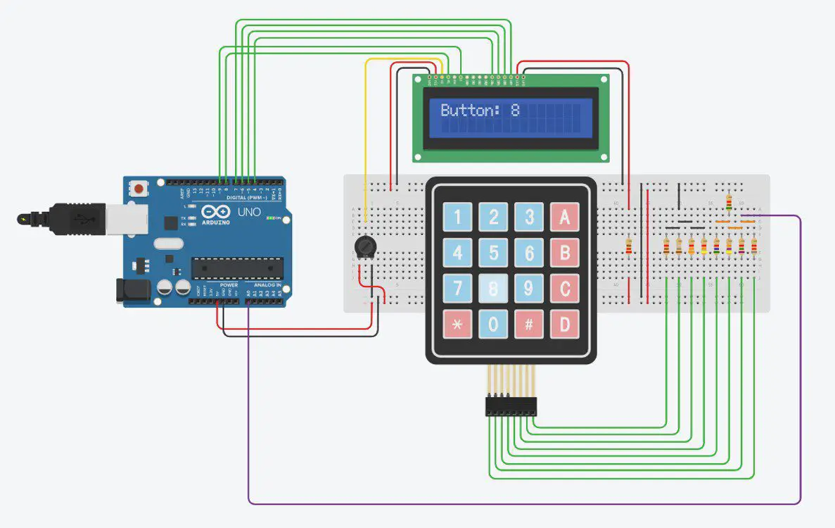
Note – In the above example breadboard layout with a wired LCD, I have used A0 as the keypad input. In the photos, video example and code below, I have used an LCD shield and have therefore used A1 as A0 is used by the shield.
Here is the code:
//Michael Klements
//The DIY Life
//5 April 2020
#include <LiquidCrystal.h>
int keyIn = 0; //Variable for keypad input
int keyVals [16] = {423, 454, 503, 562, 429, 459, 507, 565, 451, 480, 525, 579, 462, 487, 531, 585}; //Array to store keypad numerical values
char keys [16] = {'1','2','3','A','4','5','6','B','7','8','9','C','*','0','#','D'}; //Key characters corressponding to each numerical value
int range = 1; //Tolerance above or below the numerical value
int buzzerPin = 2; //Buzzer used in video for key sound
LiquidCrystal lcd(8, 9, 4, 5, 6, 7); //Assign LCD screen pins, as per LCD shield requirements
void setup()
{
pinMode(buzzerPin, OUTPUT);
lcd.begin(16,2); // columns, rows. use 16,2 for a 16x2 LCD, etc.
lcd.clear();
lcd.setCursor(0,0); //Display some text on LCD then clear it
lcd.print("Keypad");
lcd.setCursor(0,1);
lcd.print("One Input");
delay(2000);
lcd.clear();
}
void loop()
{
keyIn = analogRead(A1); //Read in keypad input
String temp = ""; //Create a variable to store the key character
for (int i=0; i<=15; i++) //Run through the array of button values
{
if (keyIn >= keyVals[i]-range && keyIn <= keyVals[i]+range) //If the measured value is in the range of one key
{
temp = keys[i]; //Set temp equal to the character for that key
digitalWrite(buzzerPin, HIGH); //Sound buzzer
delay(100);
digitalWrite(buzzerPin, LOW);
}
}
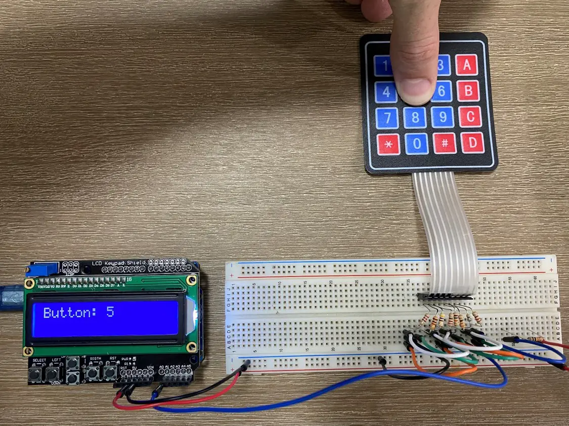
lcd.print("Button: ");
lcd.print(temp); //Display button character on the LCD
delay(1000); //Wait one second
lcd.clear(); //Clear the display
}
There are four variables used for the keypad input, the first is keyIn which is used to stored the value read on the analogue input. The second is an array of 16 values used to store the raw button input values which you’ll need to update once in the beginning for each button using your Serial Monitor or LCD. The third is a character array which stores the key symbol related to each button. The fourth is an allowable range, you may see that when you push a key it displays 512 and the next time 511. If your inputs vary slightly then this range allows you to accept values slightly higher or lower, this usually only needs to be 1 or 2 and can cause problems with overlap if higher.
The initial functions in the setup loop are all related to the LCD display, you can read up on these in our guide to connecting an LCD display to an Arduino.
In the loop function we read in a value from the analogue input, then cycle through the button keyValue array looking for a value which corresponds to the measured value within the range allowance and if one is found then the corresponding key character is saved to the variable temp which is then displayed on the LCD for 1 second before being cleared.
I’ve also added a small buzzer in the video and code to provide audible feedback when a button is pressed, similar to a security keypad.
The only challenging part of this code is determining what value is measured for each button pressed on your keypad. In order to do this you can either use the Arduino IDE serial monitor or you can simply display the measured value directly onto your LCD (Use the line lcd.print(keyIn) right after you read your analogue input) and make a note of each value displayed for each button pressed. You’ll then need to update the input array keyVals with these numbers corresponding to each character in the array keys.
Once you’ve found and set your button values, upload the final code to your Arduino and try it out, your LCD should display the character corresponding to each button you press.
Now you’ll be able to create better keypad based Arduino projects with more available IO!
Have you used this method or a similar method to connect your 4×4 keypad to your Arduino more efficiently? Let us know in the comments section below.
Share This Guide:
If you found this tutorial useful, please share it to help others out as well.
Hallo Michael,
Leuk project, maar omdat er geen waarden zijn voor de tweede weerstanden ben ik gestopt met dit projectje.
hello this is what have been looking for long now, thank you it is such a helpful information
Excellent! I am starting a project that I am running out of digital pins quickly.
I am using a 4 X 4 keypad to change the frequency on a LoRa radio.
That’s great, I haven’t tried any LoRa based projects yet. I really need to!
Have you set any other values for the A/B/C/D buttons on the 4 X 4? I want to use one like an enter, one as a cancel, and the other two as an increase value by 0.1
I think you can make the values more distinct if the resistors are 47, 100,150 and 220 for the row and 270,470,680,910 for the columns with the ‘top’ resistor set to 680 Ohms. The differences between readingsappear to be a maximum when the top resistor is set to the average of all the sums of the bottom resistors.
Yes, those look like they create a good spread of resistance.
That’s great, I am starting a project .
Hello Michael, & DIY Life Community.
Thanks For the great explanation and writeup.
I know it works, but I did not know “How It Works”.
Kind Regards,
Jim F, Calgary Alberta Canada
Hi Jim,
Thanks for the feedback! Each key connects a different set of resistors which in turn creates a unique resistance “signature” for that particular key. The Arduino looks at the resulting voltage output and is then able to determine what resistor combination resulted in that voltage, which then tells it which key was pressed.
Hope this helps!
Hie i have managed to set up the keypad as advised but upon pressing the buttons i am not getting good results. When i press the key 1, i get 49 0n my lcd, 2 gives me 50 as so forth. What could be the problem?
You’ve probably got resistors of slightly different values to mine, so you’ll need to re-calibrate your readings to output the correct number.