In this project, we will connect an ultrasonic sensor (HC-SR04) to an Arduino and use it to display a measurement on the serial monitor and then an LCD screen. This covers both the physical connections and the programming required to get the ultrasonic sensor to work. If this is your first project then we recommend that you familiarise yourself with programming an Arduino and connecting an LCD to an Arduino.
We will be using the HC-SR04 sensor (buy here). The sensor has four pins, the VCC and GND pins for power supply and the trig and echo pins for signal information. The sensor also has an ultrasonic transmitter and receiver with an oscillator to generate a 4 Khz Ultrasonic sound that allows you to measure distances up to 2 meters.
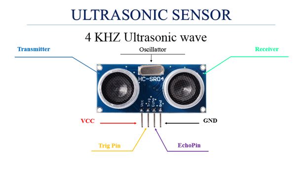
The sensor works by creating a 10 microsecond pulse and then measuring the duration taken by that pulse to reach the object then bounce back. Knowing the speed of sound in air, we can then calculate the distance of the object which reflected the pulse. Remember that the pulse travels to the object and then back again so we need to divide the time by two to calculate the distance.
What You’ll Need To Connect An Ultrasonic Sensor To An Arduino
- Arduino (Uno Used in this Example) – Buy Here
- HC-SR04 Ultrasonic Sensor – Buy Here
- Breadboard – Buy Here
- Jumper Wires – Buy Here
- Optional – LCD Screen (Hitachi HD44780 Driver) – Buy Here
- Optional – 10K Potentiometer (To change contrast) – Buy Here
- Optional – 220Ω LED Backlight Resistor – Buy Here
How To Connect An Ultrasonic Sensor To An Arduino
Assembling The Circuit – Serial Monitor
The ultrasonic sensor has four pins, the first one is the GND pin, the second is the echo pin, we will read the reflection signal from it. Then we have the trig pin which we’ll use to transmit the ultrasonic wave and the last pin is Vcc which is used to provide 5V to power the sensor.
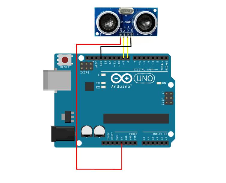
Plug the sensor into your breadboard and then use the jumpers to connect the GND pin to 0V/GND and the Vcc pin to 5V. Make sure that you plug in leads from the Arduino to your 0V and 5V tracks as well.
Next connect the Trig pin to the Arduino digital pin 9 and the Echo pin to the Arduino digital pin 8.
Assembling The Circuit – LCD Display
If you’d like to display the distance measurement on an LCD display, connect the ultrasonic sensor as per the above arrangement.
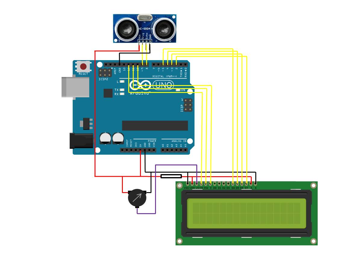
Now connect the LCD screen as per the instructions in our guide on connecting an LCD to an Arduino.
Programming The Arduino
Displaying The Distance On The Serial Monitor
Now you can begin the coding. For the first example, we will display the measurement taken from the ultrasonic sensor on the Serial monitor facility.
// Michael Klements
// Ultrasonic Sensor
// 24 August 2017
// www.the-diy-life.com

int triggerPin = 9;      //Define IO pins
int echoPin = 8;

long duration;
double distance;

void setup()
{
  pinMode(trigerPin, OUTPUT);   //Define pin
  pinMode(echoPin, INPUT);
  Serial.begin(9600);           //Starts the serial communication
}

void loop()
{
  digitalWrite(triggerPin, LOW);   //Reset the trigger pin
  delay(1000);
  digitalWrite(trigPin, HIGH);     //Create a 10 micro second pulse
  delayMicroseconds(10);
  digitalWrite(trigPin, LOW);
  duration = pulseIn(echoPin, HIGH); //Read the pulse travel time in microseconds.
  distance= duration*0.034/2;        //Calculate the distance - speed of sound is 0.034 cm per microsecond
  Serial.print("Distance: ");        //Display the distance on the serial monitor
  Serial.println(distance);
}
You can also download the code here – UltrasonicSerialMonitor
First you have to define the Trigger and Echo pins. In this case they are the pins number 8 and 9 on the Arduino Board and they are named triggerPin and echoPin. Then you need a Long variable, named “duration” for the travel time that you will get from the sensor and a double variable for the distance which is measured in centimeters.
In the setup you have to define the triggerPin as an output and the echoPin as an Input and also start the serial communication to display the results on the serial monitor.
The code then runs through a continuous loop where the trigger is reset, the program waits one second and then creates a 10 microsecond pulse. The time it takes the pulse to return is then measured and this is used to calculate the distance. If the object is 10 cm away from the sensor, and the speed of the sound is 340 m/s or 0.034 cm/µs the sound wave will need to travel for 294 u seconds. But the time you will measure from the Echo pin will be double that because the sound wave needs to travel forward and be reflected backward. In order to get the distance in cm we need to multiply the measured travel time from the echo pin by 0.034 and then divide it by 2.
The result is then sent to the serial monitor. The serial monitor will display a newly measured distance every 1 second.
Displaying The Distance On An LCD Screen
In the second example, we will display the measured distance on an LCD screen which is connected to the Arduino.
// Michael Klements
// Ultrasonic Sensor
// 24 August 2017
// www.the-diy-life.com

#include <LiquidCrystal.h>

LiquidCrystal lcd(12, 11, 10, 5, 4, 3, 2);  //Assign the LCD screen pins

int triggerPin = 9;      //Define IO pins
int echoPin = 8;

long duration;
double distance;

void setup()
{
  pinMode(trigerPin, OUTPUT);   //Define pin
  pinMode(echoPin, INPUT);
  lcd.begin(16,2);              //Start the LCD screen, define the number of characters and rows
  lcd.clear();                  //Clear the screen
  lcd.setCursor(0,0);           //Set the cursor to first character, first row
  lcd.print("Distance:");        //Display this text
}

void loop()
{
  digitalWrite(triggerPin, LOW);   //Reset the trigger pin
  delay(1000);
  digitalWrite(trigPin, HIGH);     //Create a 10 micro second pulse
  delayMicroseconds(10);
  digitalWrite(trigPin, LOW);
  duration = pulseIn(echoPin, HIGH); //Read the pulse travel time in microseconds.
  distance= duration*0.034/2;        //Calculate the distance - speed of sound is 0.034 cm per microsecond
  lcd.setCursor(0,1);               //Set cursor to column 0, row 1
  lcd.print(distance);                     //Display the distance
  lcd.print(" cm");
}
You can also download the code here – UltrasonicLCD
Once you’ve got the basics working, you can try changing the measurement units and experiment with different timing. You could also mount the ultrasonic sensor onto a servo and rotate it to get measurements all around your Arduino.
If you have any questions or comments, please leave them in the comments section below.
I had to fix your code a little for it to go together (triggerpin spelt differently).
But it’s currently working on my thingi!
Thanks for the help!
Thank you, will get the code fixed!
Hello, how can I get the exact distance between object and sensor? Because when I run the coding and I try to get a distance, it screen out tally distance with different value. How I can the exact distance. Thank you.
Hi Muhamad,
If you’re getting an incorrect distance then there is either something wrong with your timing or with the way your ultrasonic sensor works. The distance is calculated based on how long it takes the pulse to return to the sensor so if it is incorrect then there must be a timing problem.
good