Being able to control your Arduino using an infrared remote control opens up a lot of possibilities for inputting data into your Arduino and getting it to respond to certain commands in order to change functionality or drive components. You could use an infrared remote control to control a robot or car, turn a light bulb on or off or change your program from one function to another.
You can use almost any infrared remote control to control your Arduino as you’re going to be decoding the signal sent from the control. Some Arduino kits are sold with a remote control or your could use your control from a TV, appliance or toy.
Pushing a button on the remote control causes the control to emit a coded infrared signal which is unique to each button on the control, allowing the appliance to determine which button was pressed and respond accordingly.
What You’ll Need To Control Your Arduino With An Infrared Remote Control
- Arduino (Uno Used Here) – Buy Here
- Infrared Sensor – Buy Here
- Infrared Remote Control (Old TV Remote) – Buy Here
- 10K Resistor – Buy Here
- 3 x 220Ω Resistor (Optional, To Control) – Buy Here
- RGB LED (Optional, To Control) – Buy Here
- Breadboard – Buy Here
- Jumper Wires – Buy Here
How To Connect Your IR Sensor To Your Arduino
Your IR sensor will have three pins, these are 1 DATA, 2 GND and 3 VCC. To connect your sensor to your Arduino, you’ll need to power your sensor with 5V and GND on your Arduino and then connect your 1 DATA pin to an available output pin with a 10K resistor to 5V, as shown in the breadboard example below:
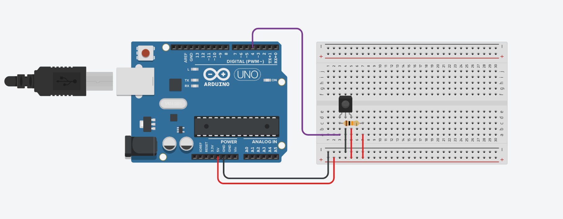
This is the only circuit you need to connect in order to be able to read IR signals from a remote control. In this example, we’re going to be using a remote control to control the brightness and colours of an RGB LED.
We’re going to use the numerical keypad so that numbers 1,2,3 increase the brightness of red, green and blue correspondingly, 4,5,6 decrease the brightness and 7,8,9 turn each colour off completely. The power button is additionally used to turn off all three colours completely.
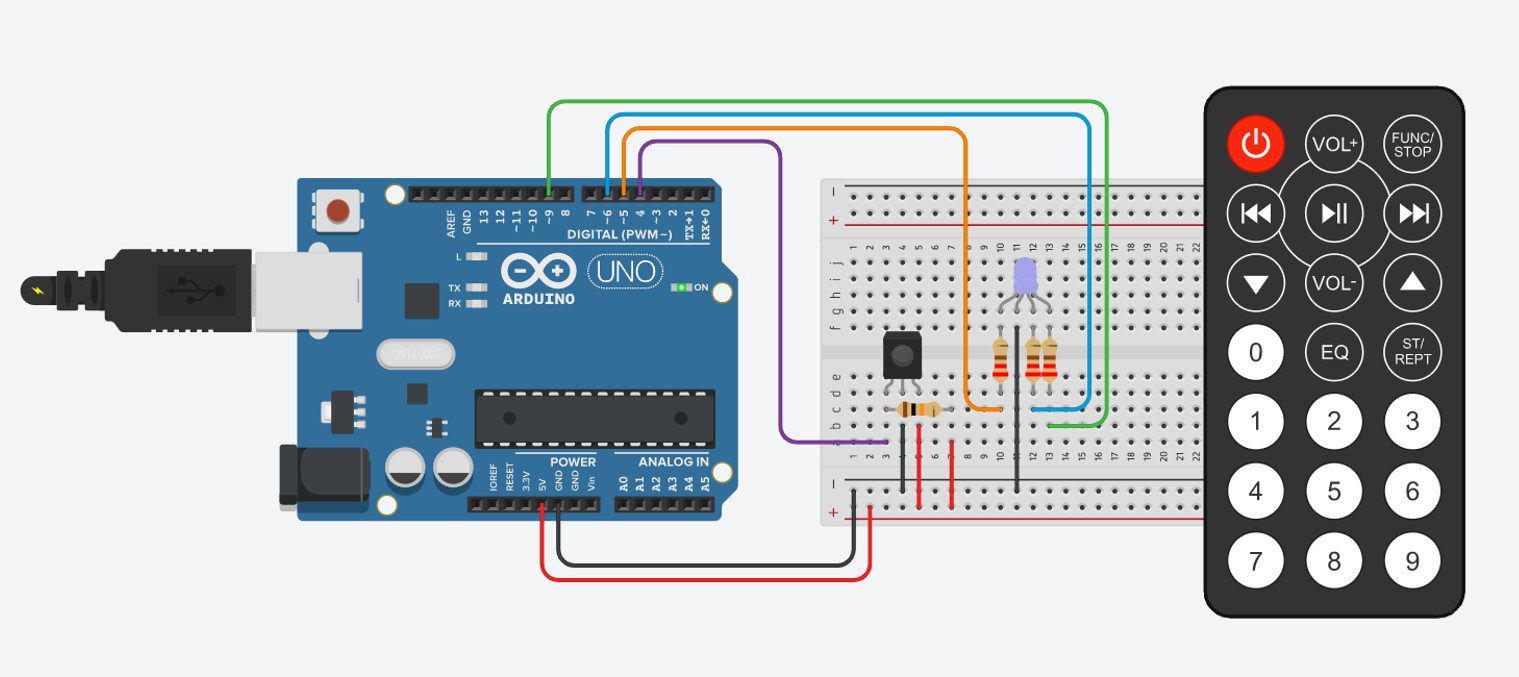
We’ll need to add the LED and resistors to our breadboard as shown:
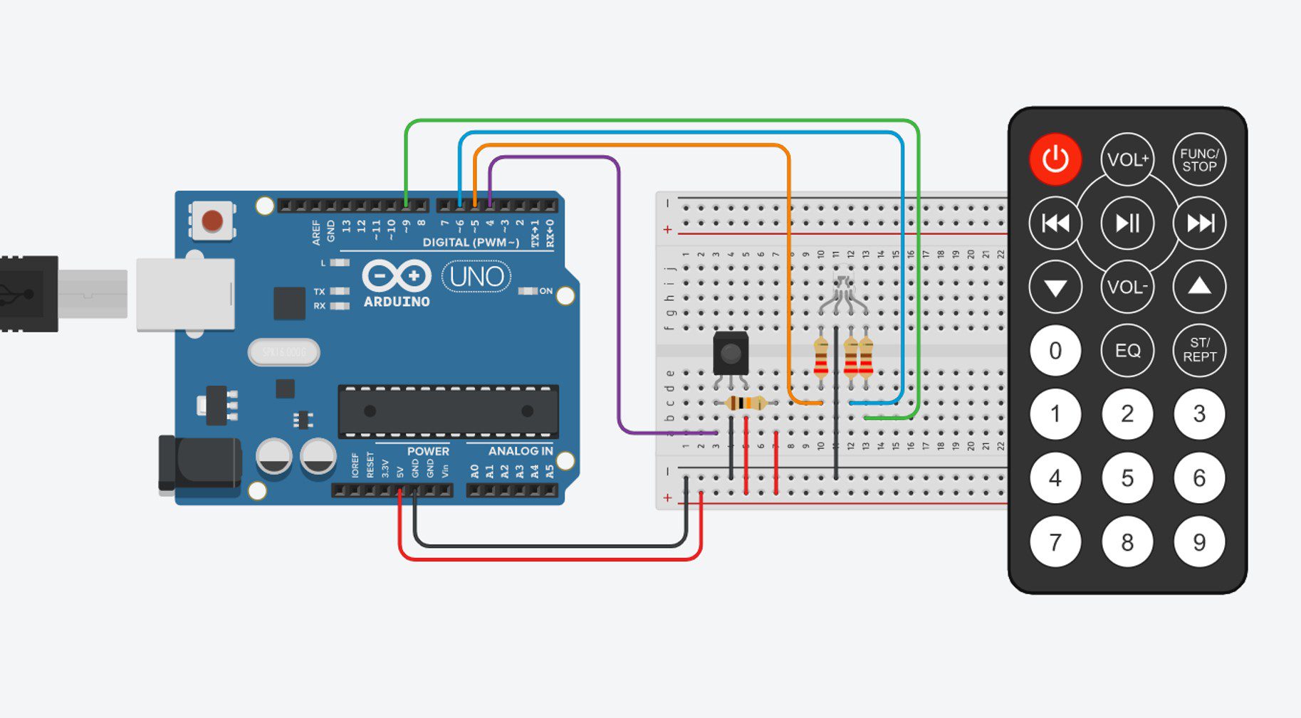
And that’s all you need to connect to be able to control your RGB LED with a remote control.
The Code
Now lets look at the code we need in order to read the value from our remote control and use it to control our RGB LED. We’ll be using the IRremote.h library to read the value from the remote control and convert the signal into a HEX value which we can then use to control our LED.
Here is the sketch:
//The DIY Life
//Michael Klements
//24 January 2020

#include <IRremote.h>

int iRPin = 4;            //IR sensor connected to Pin 4
IRrecv irrecv(iRPin);     //Create an IR object of the class
decode_results results;

int ledRPin = 5;      //Define LED pin numbers
int ledGPin = 9;
int ledBPin = 6;

int rVal = 512;       //Define initial brightness values - mid brightness
int gVal = 512;
int bVal = 512;

void setup()
{
  //Serial.begin(9600);     //Only used to get HEX value for each button
  irrecv.enableIRIn();        //Start the IR receiver
  pinMode(ledRPin, OUTPUT);   //Define the LED pins
  pinMode(ledGPin, OUTPUT);
  pinMode(ledBPin, OUTPUT);
}

void loop()
{
  if (irrecv.decode(&results))  //Wait for an IR signal to be received
  {
    //Serial.println(results.value, HEX);   //Only used to get HEX value for each button
    changeLED(results.value);    //Change the LED accordingly
    irrecv.resume();             //Wait for next signal
    delay(100);
  }
}

void changeLED(unsigned long value)
{
  switch (value)  //Determine which button has been pressed
  {
    case 0xFD08F7:    //Button 1 Pressed - Brighten Red
      if(rVal<=973)   //Stops red value from going too high, out of range
        rVal = rVal + 50;  //Increase red brightness
      analogWrite(ledRPin,rVal);
      break;
    case 0xFD28D7:      //Button 4 Pressed - Dim Red
      if(rVal>=50)    //Stops red value from going too low, out of range
        rVal = rVal - 50;  //Decrease red brightness
      analogWrite(ledRPin,rVal);
      break;
    case 0xFD18E7:      //Button 7 Pressed - Turn Red Off
      analogWrite(ledRPin,0);
      break;
    case 0xFD8877:    //Button 2 Pressed - Brighten Green
      if(gVal<=973)
        gVal = gVal + 50;
      analogWrite(ledGPin,gVal);
      break;
    case 0xFDA857:      //Button 5 Pressed - Dim Green
      if(gVal>=50)
        gVal = gVal - 50;
      analogWrite(ledGPin,gVal);
      break;
    case 0xFD9867:      //Button 8 Pressed - Turn Green Off
      analogWrite(ledGPin,0);
      break;
    case 0xFD48B7:    //Button 3 Pressed - Brighten Blue
      if(bVal<=973)
        bVal = bVal + 50;
      analogWrite(ledBPin,bVal);
      break;
    case 0xFD6897:      //Button 6 Pressed - Dim Blue
      if(bVal>=50)
        bVal = bVal - 50;
      analogWrite(ledBPin,bVal);
      break;
    case 0xFD58A7:      //Button 9 Pressed - Turn Blue Off
      analogWrite(ledBPin,0);
      break;
    case 0xFD00FF:      //Power Button Pressed - Turn All LEDs Off
      analogWrite(ledRPin,0);
      analogWrite(ledGPin,0);
      analogWrite(ledBPin,0);
      break;
  }
}
Download the sketch – IRRemote
I’ve put comments into the code to guide you through it and explain what each section does.
The two Serial lines which are commented out are needed when you first set up the code. You’ll need to uncomment the lines, run the sketch with your Serial monitor open and then push the 10 buttons used in this example on your own remote control in order to check and record the HEX values, it is unlikely that they will be the same as used in this example unless you happen to have the same remote. Record the values which are displayed for each button and then replace the values in the code. For example, replace 0xFD00FF for the power button with the new code shown on your Serial monitor. You’ll leave the 0x preceding the 6 digit code which you’ll have displayed.
Once you’ve made these changes then the code should run and your Arduino should respond to your remote control button pushes.
The code in the changeLED function is used to respond to each button press by using a switch statement to switch between the different buttons. You can add or remote buttons to this statement by adding or removing additional case lines.
If you use a different remote control or two remote controls, simply replace the values next to each case to correspond with your new remote’s values displayed in the Serial monitor. For two remote controls, duplicate cases line with your additional value as a second option.
You should now know enough to get your Arduino to respond to commands sent to it by one or more IR remote controls. Have you tried connecting an IR remote to your Arduino? What did you build and how did it go for you? Let us know in the comments section below.