In this tutorial, we’re going to be looking at how to use an L293D motor driver to drive a DC Motor for your Arduino projects. This has some great applications for projects such as balancing robots, smart and autonomous vehicles and other moving systems.
The L293D chip is a very versatile and affordable chip, you can get a pack of them for less than a dollar each and they’re able to control up to four solenoids, two DC motors or a uni-polar stepper motor with up to 600mA per channel.
This project assumes that you know the basics of Arduino programming, otherwise follow our guide on getting started with Arduino.
What You’ll Need For This Project
- Arduino (Uno Used Here) – Buy Here
- L293D Motor Driver – Buy Here
- DC Motor – Buy Here
- Or Geared Motor For Robot/Car – Buy Here
- Potentiometer – Buy Here
- Breadboard – Buy Here
- Jumper Wires – Buy Here
- Batteries & Holder – Buy Here
Information on the L293D Motor Driver
Before we start with the circuit and programming your Arduino, let’s have a look at the L293D motor driver chip and some of its functionality and limitations.
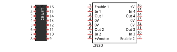
The pin descriptions are as follows:
- 2, 7, 10, 15 (In 1, In 2, In 3, In 4)
- Each of the four channel’s digital signal input pin
- 3, 6, 11, 14 (Out 1, Out 2, Out 3, Out 4)
- Each of the four channel’s output pin
- 1 (Enable 1)
- Channel 1 & 2 enable pin
- 9 (Enable 2)
- Channel 3 & 4 enable pin
- 4, 5, 12, 13 (0V)
- Power GND
- 16 (+V)
- Power supply for the driver, positive input 4.5V to 36V
- 8 (+Vmotor)
- Power supply for load (motor), positive input 4.5V to 36V
In order to use the L293D motor driver to drive a DC motor, there are two available connection options. The first is a simple connection between the output of the driver and ground which enables the speed of the motor to be controlled but rotation only in a single direction. The second is to connect the motor between two driver outputs, which enables both the motor’s speed and direction to be controlled.
Connecting The Motor Driver To Your Arduino
We’re going to be setting up two circuits to control the motor. One to take an input from a potentiometer so that you can adjust the potentiometer to control the motor speed and direction, and a second to interface the motor and motor driver with the Arduino.
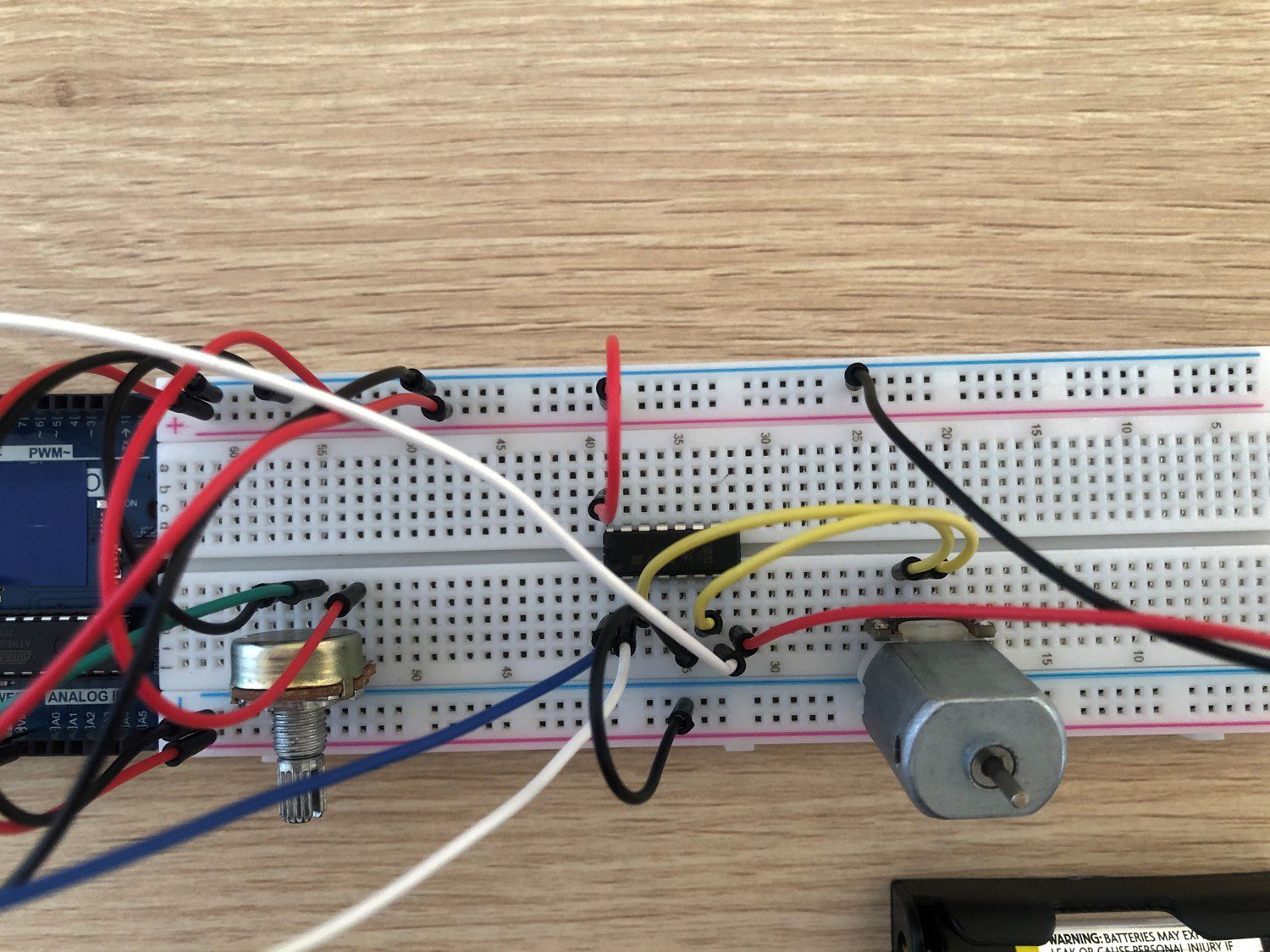
This is how the two circuits should be set up on a breadboard:
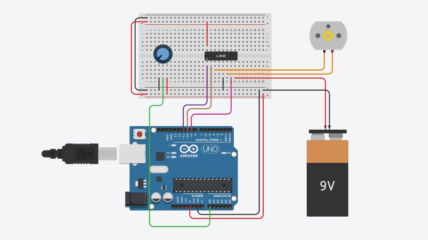
The potentiometer circuit is a straight forward analogue input circuit with the potentiometer wiper connected to the Arduino analogue input 0. This is going to be used to control the motor’s direction and speed. The potentiometer’s midpoint corresponds with zero speed and turning it clockwise moves the motor forward with increasing speed and anti-clockwise moves it in reverse with increasing speed. You could also wire up a push button to control the motor direction if you’d like and this will give you the full potentiometer range to control the motor’s speed.
Unless your motor is really small, you’ll need to power it separately, not through your Arduino’s on-board supply. This is easily done using an external battery pack or power supply. This can be the same supply as you are using for your Arduino if it is able to provide adequate voltage and has enough capacity. Make sure that your nattery is the correct voltage for your motor, use a small battery pack (one with 2 x 1.5V AA batteries) for lower voltage motors and a larger 9V battery for larger motors, check your motor data sheet if you are unsure.
The remaining connections to your L293D motor driver are quite simple.
The motor is connected to pins 3 & 6 (Out 1 & Out 2) on the driver, they can be connected either way around and this will only affect the motor forward and reverse directions in relation to the potentiometer movement.
The motor driver’s control pins 7, 2 & 1 (In 2, In 1 & Enable 1) are connected to Arduino pins 9, 10 and 11 respectively.
The Code to Drive A DC Motor Using an L293D Motor Driver
Now that you’ve made the connections between your components and your driver and Arduino, lets have a look at how to program your Arduino to control the motor.
Here is the code:
//The DIY Life
//4 November 2019
//Michael Klements

int in2Pin = 9;       // Define pins used for L293D
int in1Pin = 10;
int enable1Pin = 11;

int dir = 0;  // Define variables for motor direction and speed
int spd = 0;

void setup()
{
  pinMode(in2Pin, OUTPUT);	//Define pin modes
  pinMode(in1Pin, OUTPUT);
  pinMode(enable1Pin, OUTPUT);
}

void loop() {
  int potInput = analogRead(A0);  // Read potentiometer value
  spd = map(abs(potInput - 512), 0, 512, 0, 255); // Calculate motor speed, pot travel from midpoint
  if (potInput > 512) // Compare to potentiometer midpoint to get motor direction
    dir = 0;
  else
    dir = 1;
  driveMotor(); //Call function to drive motor at calculated speed and direction
}

void driveMotor()
{
  if (dir)
  {
    digitalWrite(in1Pin, HIGH);
    digitalWrite(in2Pin, LOW);
  }
  else
  {
    digitalWrite(in1Pin, LOW);
    digitalWrite(in2Pin, HIGH);
  }
  analogWrite(enable1Pin, spd);
}
Download the code here: L293D DC Motor Driver Code
We start by defining the three output pins which are required to drive the L293D motor driver. We then create two variables which are the parameters required to define the motors movement, its direction and its speed.
The setup loop simply defines the identified pins on your Arduino as outputs.
In the loop function we start by reading in the potentiometer set point using the Arduino’s analogue input A0.
Since we are using the potentiometer’s midpoint as zero speed and movement away from the midpoint in either direction as the speed, we need to take the absolute value of the speed after adjusting the midpoint from 512 to 0, since the analogue input will read a value between 0 and 1023. In addition to this, we need to map the speed to a range between 0 and 255, as this is the range of the Arduino’s PWM outputs. We now have the required motor speed stored in a variable spd which is between the value of 0 and 255.
Next we need to determine the direction. We know that 512 is the midpoint, so any value higher than this is the forward direction 0 and any value lower than this is the reverse direction 1.
We now call up the function which we’ve created to drive the motor. This function sets the two input pins HIGH or LOW as required for either the forward or reverse direction and then sets the speed using a PWM output according to our calculated speed value.
Upload your code and your Arduino motor driver is ready to run. You should now be able to drive your motor in either the forward or reverse directions by turning your potentiometer clockwise or anti-clockwise from its mid-point.
Have you tried using an L293D motor driver to drive a DC motor? Let us know in the comments section below, we would love to hear which projects you’ve used this driver in.
I have been looking at a simular project, however is it possible to use a L293D motor shield if so how would you code it? would it be possible to control seperate motors in this way?
Yes you can use the L293D motor driver shield, have a look at my obstacle avoiding robot car project. This uses the shield to independently control 4 motors.
at a particular pot value, motor rpm is fluctuating. why is it so?
please tell me….
Either your pot signal to the Arduino isn’t stable and is fluctuating or your power supply to your motor is not stable.
Hi, I want to control a 12V motor with a thumb roller instead of a potentiometer, the problem is that it gives 2.5V in the middle position and increases to 5V in both directions, I want to be able to control two motors one in opposite directions on the thumb roller, the motors must go in the same direction .
Etc. Stefan