In this tutorial, we’re going to be looking at how to correctly set the current limit on an A4988 stepper motor driver. These stepper motor drivers have become increasingly popular for CNC, 3D printing, robotics, and Arduino projects because they’re really cheap and easy to use, requiring just two pins to control them.
One important thing to set up when using these drivers is the motor current limit. This is especially important when you’re using a higher input voltage than what the motor is rated for. Using a higher voltage generally enables you to get more torque and a faster step speed, but you’ll need to actively limit the amount of current flowing through the motor coils so that you don’t burn your motor out.
There are two methods to do this, the one is to use a multimeter to physically measure the current flowing through one of the coils and the second method, which is the one we’re going to look at, is to calculate and then adjust the reference voltage on the driver, which doesn’t require the motor to be hooked up or powered.
Here’s a step by step video on how to set up your A4988 stepper motor driver’s motor current limit.
What You Need To Set The Current Limit On Your Stepper Driver
- Arduino Uno – Buy Here
- A4988 Stepper Motor Driver – Buy Here
- Breadboard & Jumpers – Buy Here
- Multimeter –Buy Here
- Alligator Test Leads – Buy Here
How To Set The Current Limit On Your A4988 Stepper Motor Driver
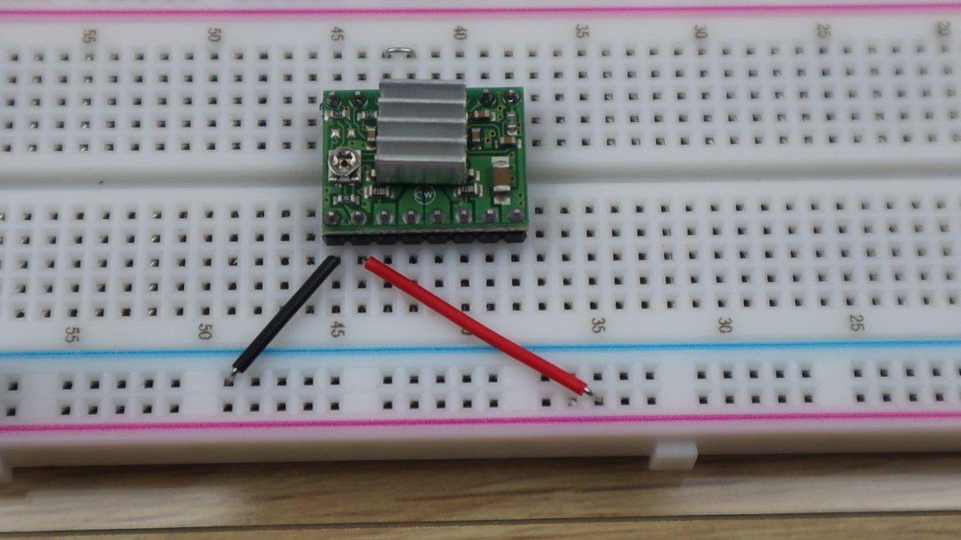
In each motor driver pack, you’ll get a small heatsink which should be stuck onto the driver chip and you’ll need to use a small screwdriver to adjust this pot to set the current limit.
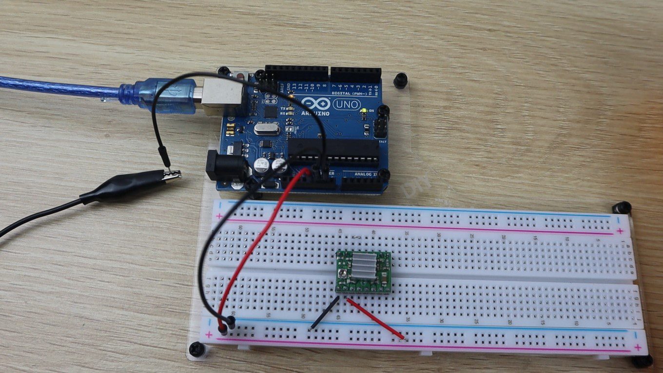
We’re going to be setting the motor current limit on a breadboard, as we need to bridge the sleep and reset pins and then supply power to the board’s logic circuit through the ground and VDD pins. The power can be supplied from the 5V supply on your Arduino.
Let’s start by hooking up our driver.
Now we need to calculate the reference voltage that we’re going to be setting.
This is done by using the following formula:
Vref = Imot x 8 x Rsen
The reference voltage is equal to the maximum motor current, multiplied by 8, and then by the current sensing resistance.
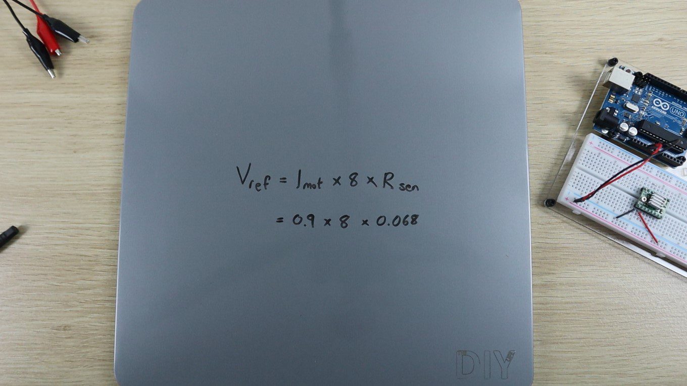
The maximum motor current can be found on the motor datasheet, ours is 0.9A. The current sensing resistance can be found on your driver’s datasheet but is most commonly 0.068 ohms for newer drivers.
Using this formula, we calculate that our reference voltage should be set to 0.49 volts.
The easiest way to set the voltage is to clip the negative multimeter lead to your Arduino’s ground pin using one alligator lead.
And then connect the positive lead to the metal part of a small screwdriver using another alligator lead.
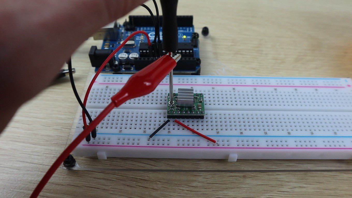
You can now simultaneously make changes to the reference voltage and read the voltage on your multimeter, making it easy to adjust.
Set your multimeter to the DC voltage measurement setting and then place the head of the screwdriver onto the potentiometer. You should now get a reading for the reference voltage. Turning the screwdriver anticlockwise decreases the voltage and clockwise increases the voltage.
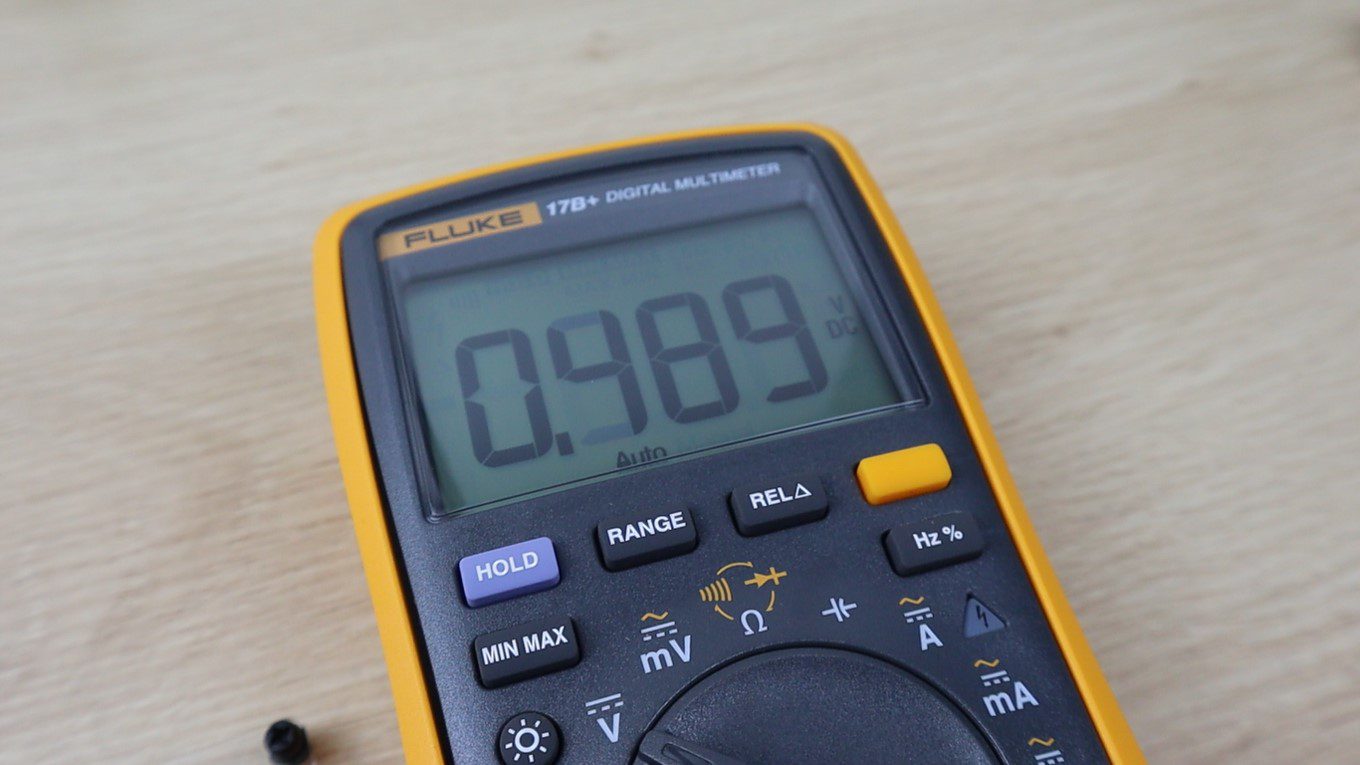
We set it to 0.49 volts, then remove and replace the screwdriver to recheck it, and you’re done. You can now finish off the rest of the connections to the Arduino or plug it into your 3D printer or stepper motor driver shield.
How do you usually set up your A4988 stepper motor driver’s motor current limit? Let me know in the comments section.
Thank you sir
Sir my potentiometer is showing 0 voltage.what should I do.please tell me sir
If you’re getting 0V you’re either measuring from the wrong points or there is a problem with your driver/wiring.
For some modules the sense resistors are labelled ‘S1’ and ‘S2’ rather than ‘Rcs’. They will typically be located close to the Ax and Bx pins. A marking of ’68L0′ or ‘R068’ indicates a 0.068 Ohm resistor, while ‘R100’ indicates a 0.1 Ohm resistor (commonly seen on unbranded A4988 modules ).
How do i adjust the SPEED of the motor ?
My motor is rated for 1.68A for one phase. But there are two phases. Should I double the amperage?
No. The driver expects the maximum amps setting to be the current for a single phase. If more than one phase is activated (which depends on the microstepping selection) then the driver compensates as required.
Thank you for your tutorial, it is very detailed and comprehensive. I will study it carefully and try it out.