A Mendocino motor makes an intriguing desktop toy. The magnetically levitated rotor and lack of any batteries or power supply add to the allure. While they look quite sophisticated, Mendocino motors are actually one of the most simple forms of brushless motor. They rely on solar panels mounted directly onto the rotor and connected in opposite polarities to automatically reverse the current flowing through the windings, thereby negating the need for a commutator or any electronic control circuit. We’ll discuss this in a bit more detail further along.
Due to the relatively small size of the solar panels which are able to be mounted onto the rotor, this motor doesn’t produce much power and you won’t be able to connect it up to drive something useful. Some people have added a small fan to the end of the rotor, which looks quite nice, but also doesn’t really produce much air movement.
Here’s my video of the build and the Mendocino motor in operation, read on for the parts list and instructions.
What You’ll Need To Build Your Own Mendocino Motor
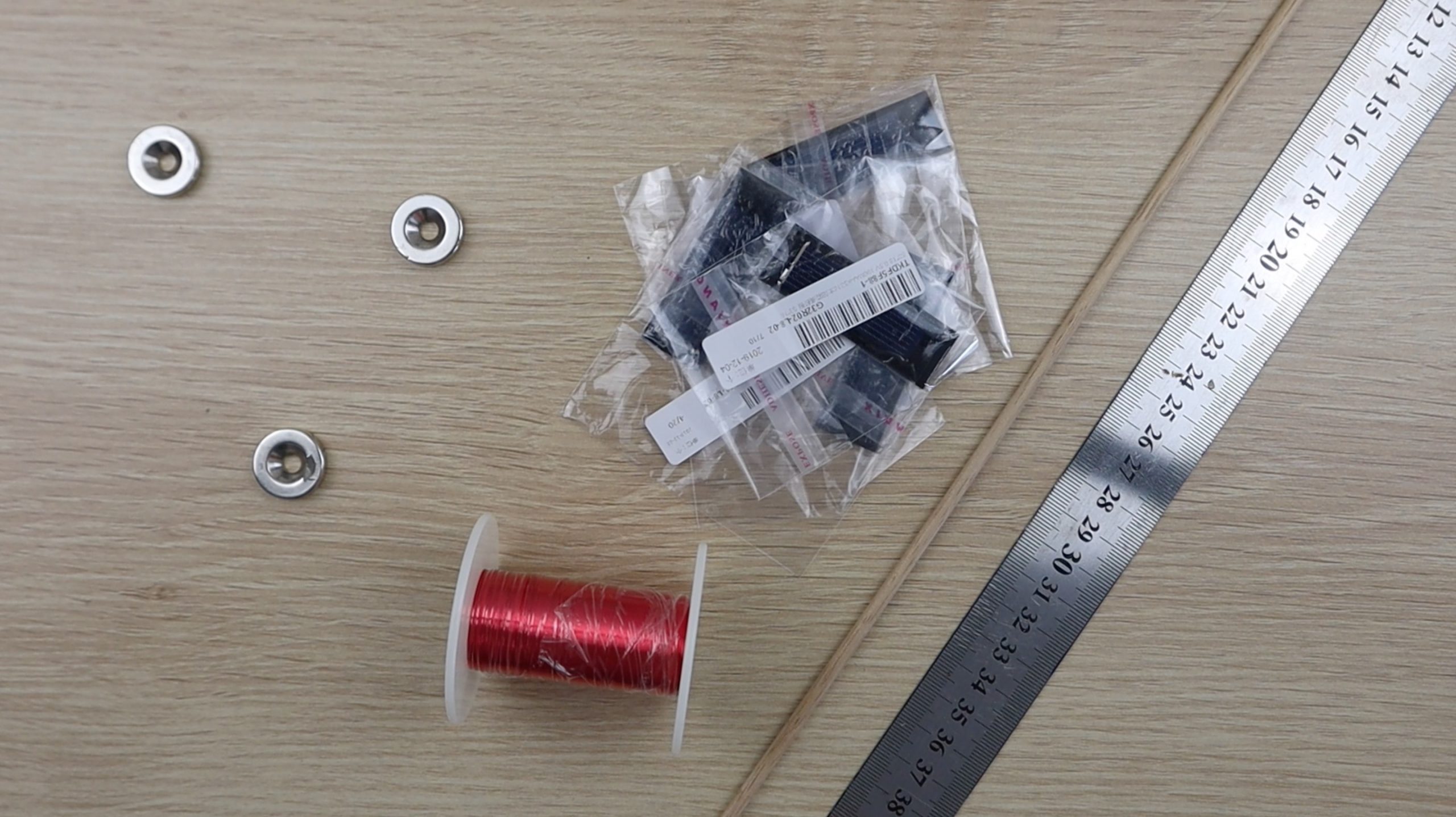
- 7 Neodynium Magnets – Buy here
- 0.2mm (32 Gauge) Magnet Wire – Buy here
- 4mm (5/32″) Wooden Dowels – Buy here
- 53x18mm Solar Cells – Buy here
- Glue Sticks & Glue Gun – Buy here
In addition to these, you’ll also need to 3D print some plastic components for the frame and rotor. You could also make these components out of cardboard or wood if you don’t have a 3D printer.
- 3D Printer Used – Buy here
You’ll also need some basic tools such as a ruler, pencil or marker, craft knife, side/wire cutters and a soldering iron.
How To Build Your Mendocino Motor
We’ll build the Mendocino motor in three stages, first building the base, then the rotor and windings and then finally testing the rotor and finishing off the motor.
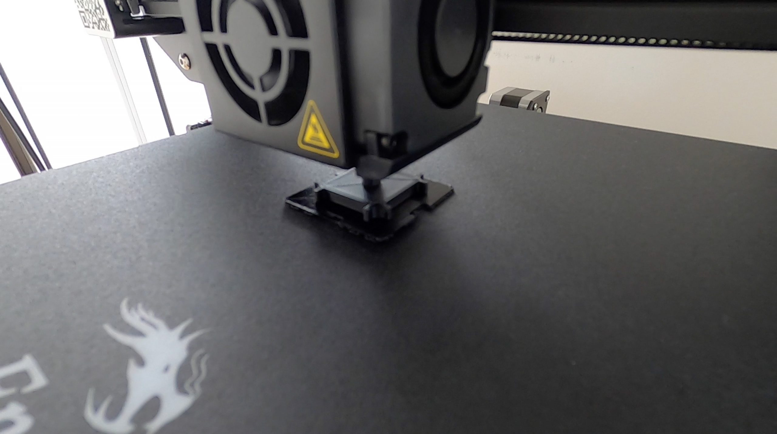
Start off by 3D printing all of the components in the download folder – 3D Print Components.
You’ll need the following quantities:
- 4 x Base Corner Blocks
- 1 x Bottom Magnet Holder
- 2 x Rotor Half
- 2 x Rotor Magnet Holder
- 1 x Rotor Reaction Support
I printed the components in black and green PLA at 195°C and 15% infill. The green PLA was only used for the rotor magnet holders, just to give the motor a bit of colour. You can use any colour or combination of colours of PLA or ABS for the components.
Assemble The Base Frame
Start off by measuring and cutting the dowel for the base, you’ll need two lengths of 9.5cm (3.75″) and two lengths of 5cm (2″).
Glue a magnet into the first corner block with the flat side inwards and then glue one of the longer dowels into the centre.
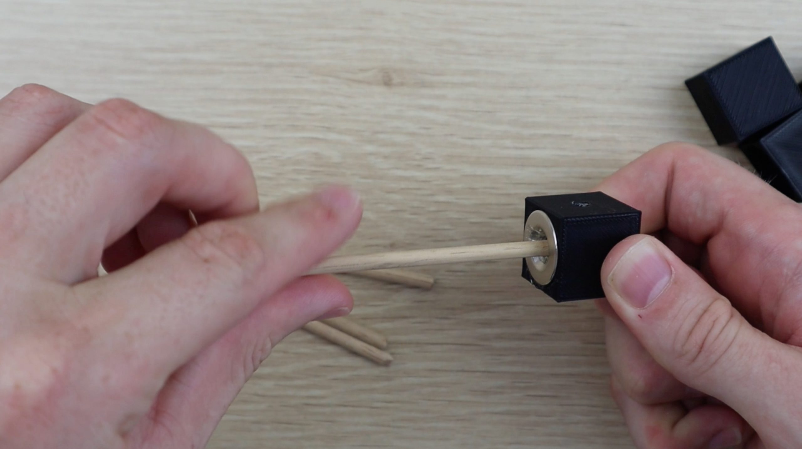
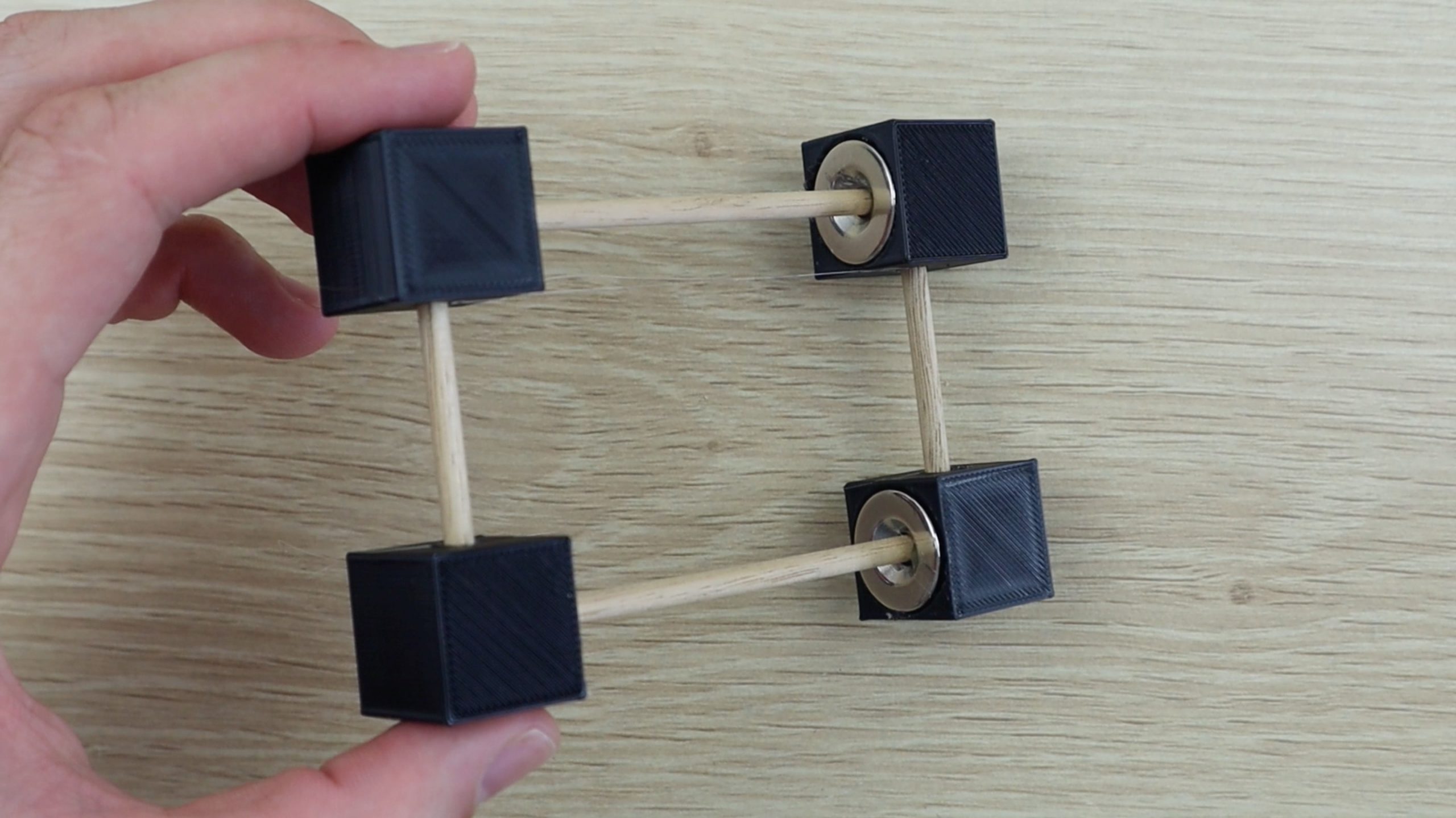
Next glue a magnet into a second corner block in the same orientation and then glue this block onto the same length of dowel. Make sure that the holes on the side of the two corner blocks face in the same direction. Also make sure that the magnets are facing each other with the same polarity, i.e. the two flat sides facing outwards (they should repel each other).
Repeat the process to make the second base length.
Next, glue one of the shorter dowels into each of the corner blocks on one length and then push the other ends into the second length. Don’t glue these into place yet, as you still need to install the rotor reaction support.
If you’re using the same components as I’ve used then you’ll want to glue the rotor reaction support into place during this step as well. I didn’t do so as I had to measure the floating height of the completed rotor once it was complete in order to design the reaction support to the correct height and distance away from the base.
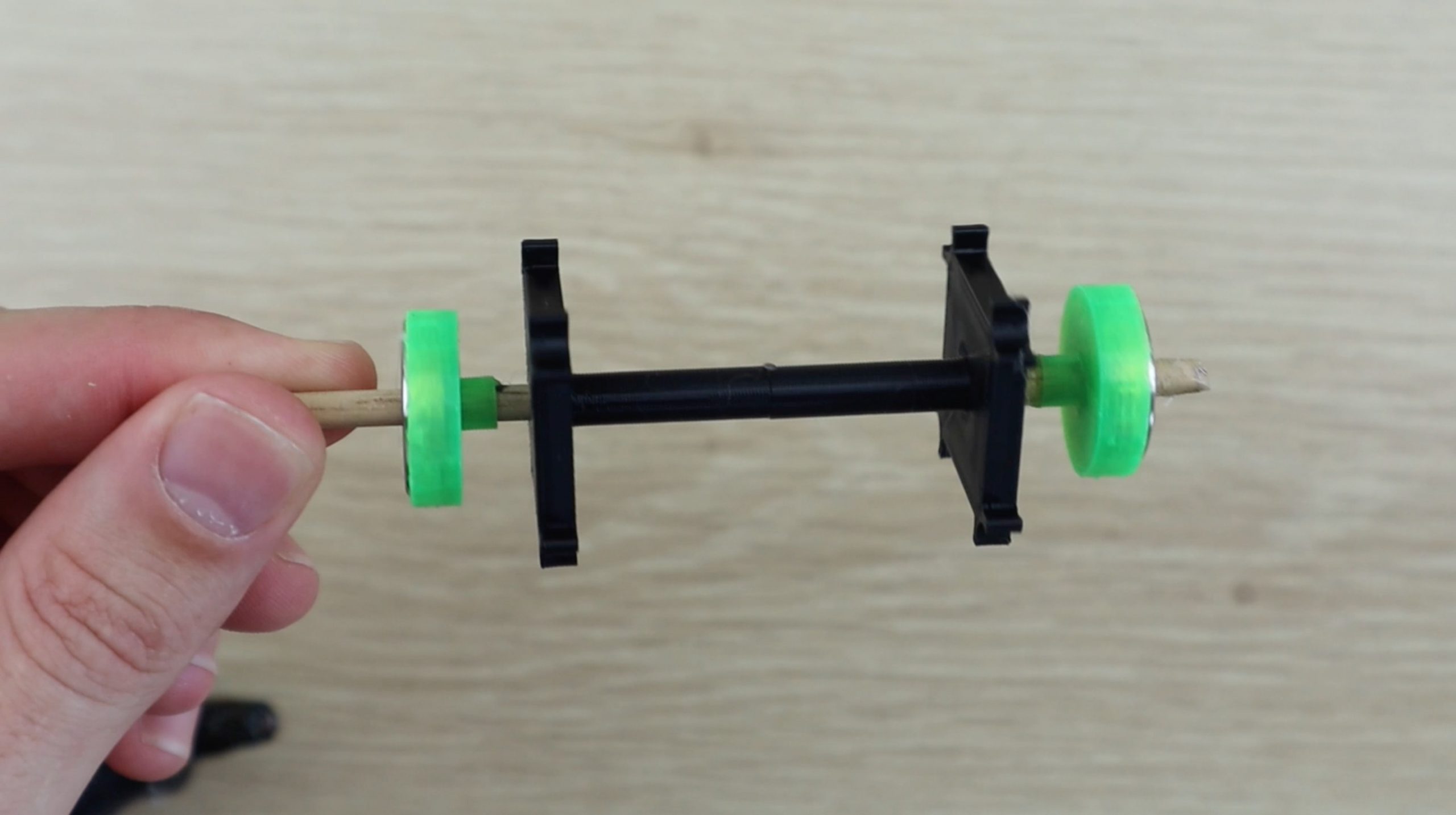
Assemble The Rotor
Next, measure a 12cm (4.75″) length of wooden dowel for the rotor. Cut one end square and use a craft knife to sharpen the other end to a point in order to minimise the contact area with the reaction support, minimising friction.
Mark the wooden dowel at 2cm (0.75″), 5cm (2″) and 8cm (3.25″) as guides for gluing the 3D printed rotor components into place.
Glue the rotor components into place as shown below. The magnets go into the magnet holders on both sides with the flat side facing outwards (away from the centre). Again, these two magnets are assembled wit the same poles facing each other (they repel each other).
It may help to watch the video at this stage to make sure that your orientations and positions are correct.
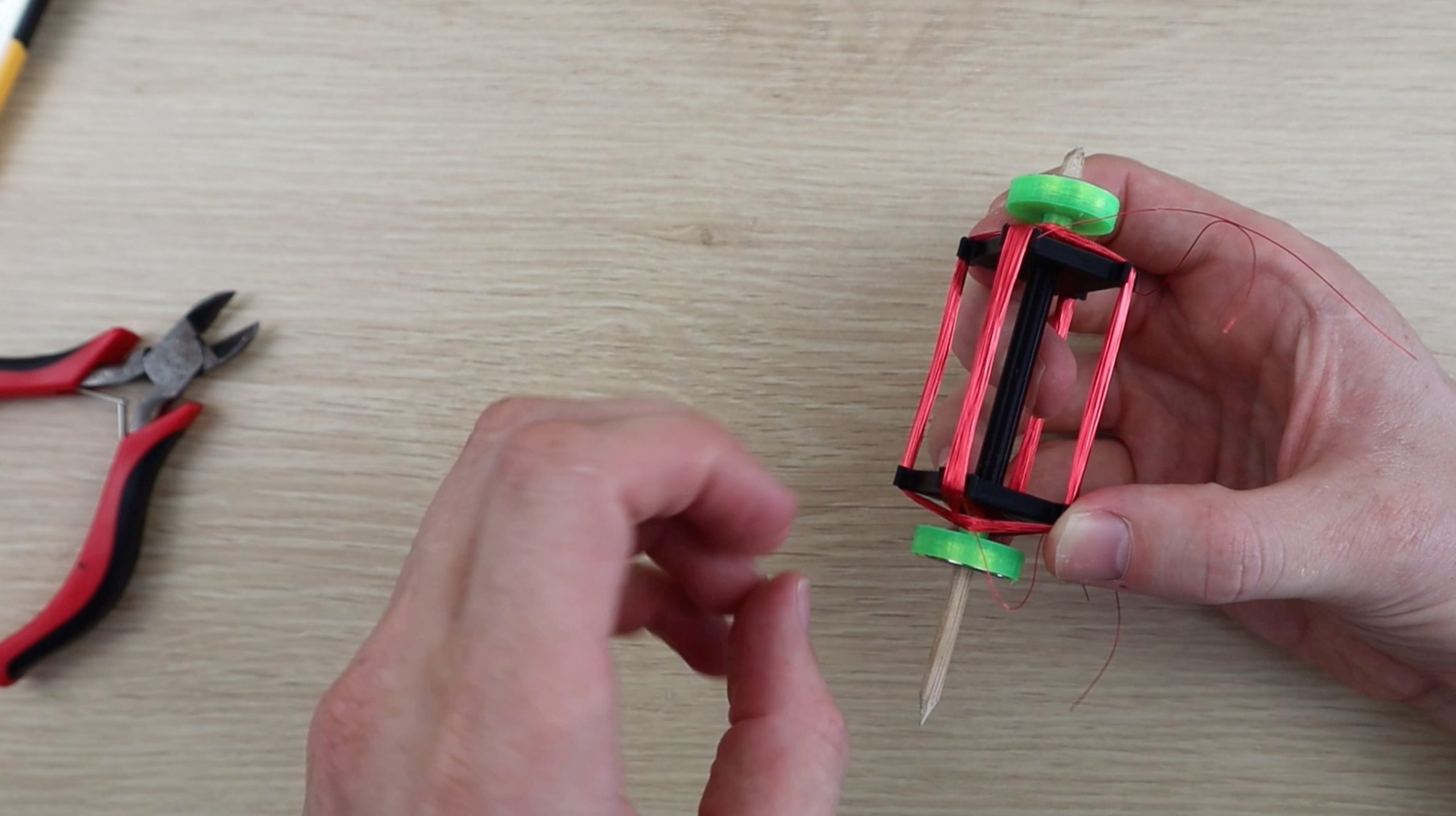
Once the plastic components are assembled, you can start making the windings. You’ll need to wind around 60-100 turns of wire for each of the two windings. Make sure that you change the rotor shaft side after every ten or so windings so that the rotor stays reasonably well balanced.
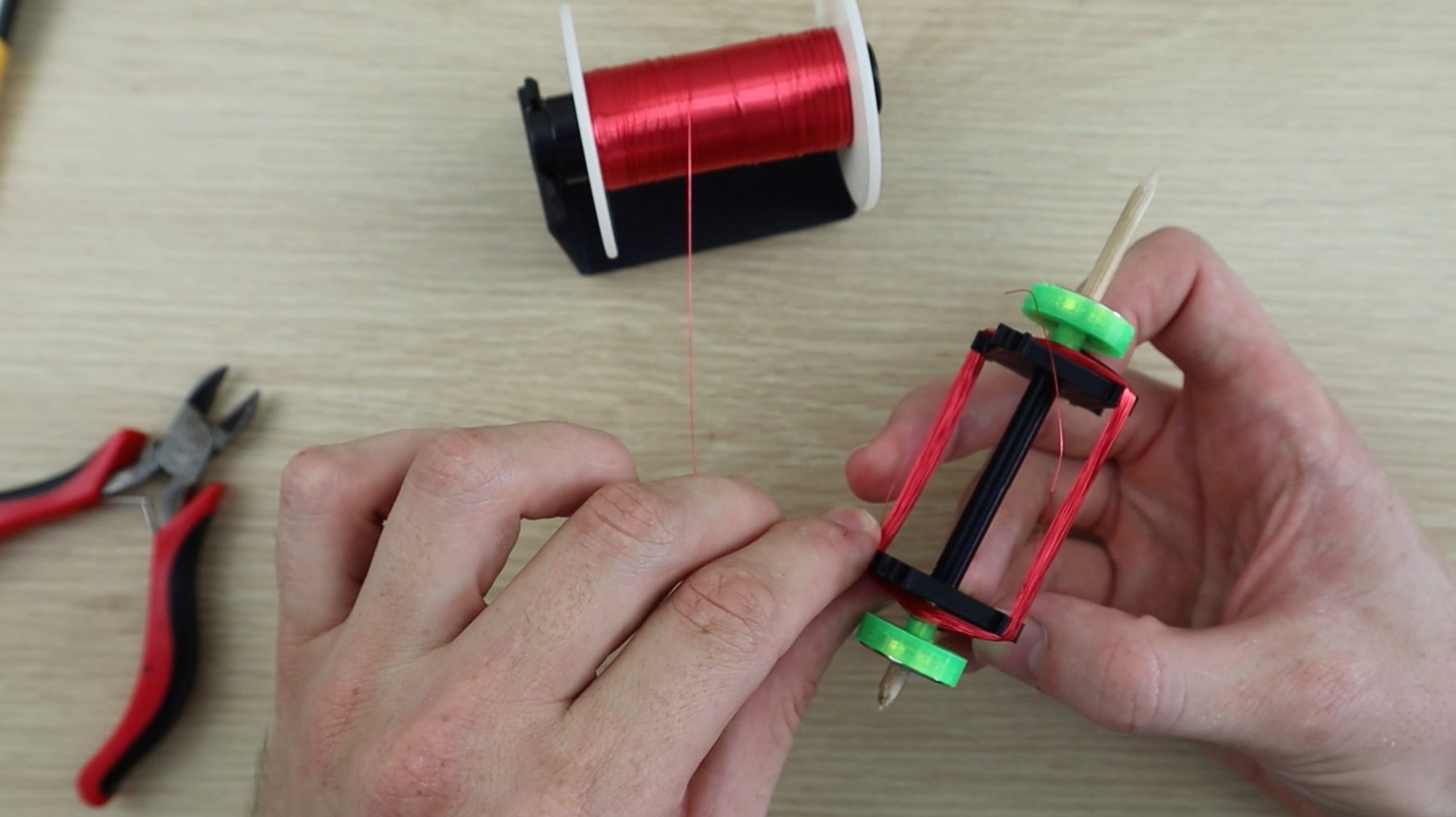
Once the first winding is complete, leave a lead on the end for connecting it to the solar panel, and then start the second winding. Make sure that you wind the same number of turns onto the second winding.
When your two windings are complete, use your craft knife to scrape some of the plastic coating off of the ends of the winding leads, so that you can make a good solder connection.
Then solder each winding as shown in the below diagram. The positive and negative terminals of opposite solar cells are soldered together and the two leads of the windings are soldered to each of these leads.
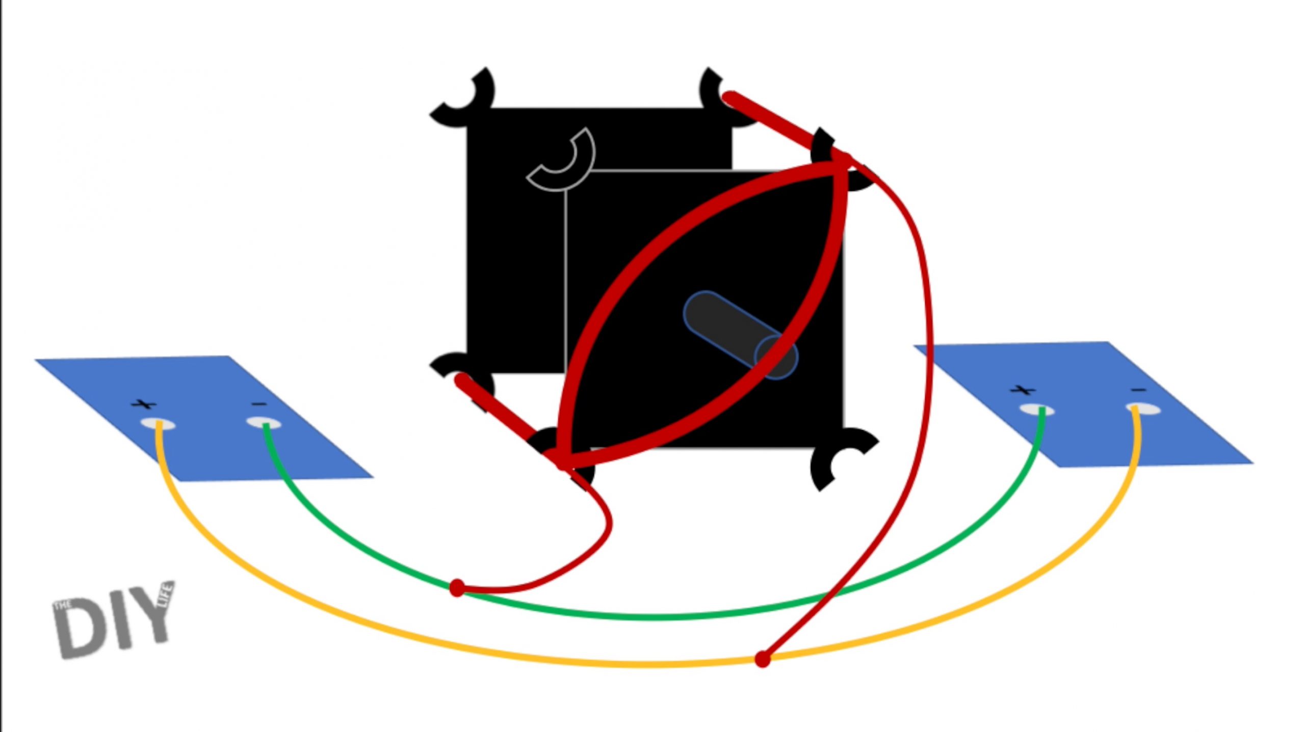
Repeat this for both sets of windings. Don’t worry about which way around the windings are connected, you’ll test this in the next step and make any changes if required.
Use some thin tape or an elastic band to temporarily hold the solar panels in place while you test the rotor and connections.
How Does A Mendocino Motor Work?
In principle, this motor produces torque by relying on one panel, the one on the opposite side of the straight section of the rotor winding which is overhead the stator magnet, producing current in the winding due to a directional light source. The current produces a magnetic field around the winding which opposes the stator magnet’s field and causes it to move away from the magnet. Because all of the components are mounted on the moving rotor, this cause the panel to move out of the light, stopping the flow of current, and the next panel into the light, producing current in the next winding. The panels are connected in opposite polarities such that current always flows in the same direction relative to the stator magnet, producing torque in the same direction. When viewed from the winding’s point of view, current is constantly changing directions, depending on which panel is under the light. This is a very simple way of replacing the need for a commutator or electronic control circuit, although it doesn’t produce much torque due to the cell’s low power to weight ratio.
You can read up a bit more on how Mendocino motor’s work on their Wikipedia page.
Testing Your Rotor & Soldered Connections
Now you’ll need to test your rotor. Glue the stator magnet into place on a flat surface and then place the base centred over the magnet. You can use the 3D printed magnet holder if you’d like.
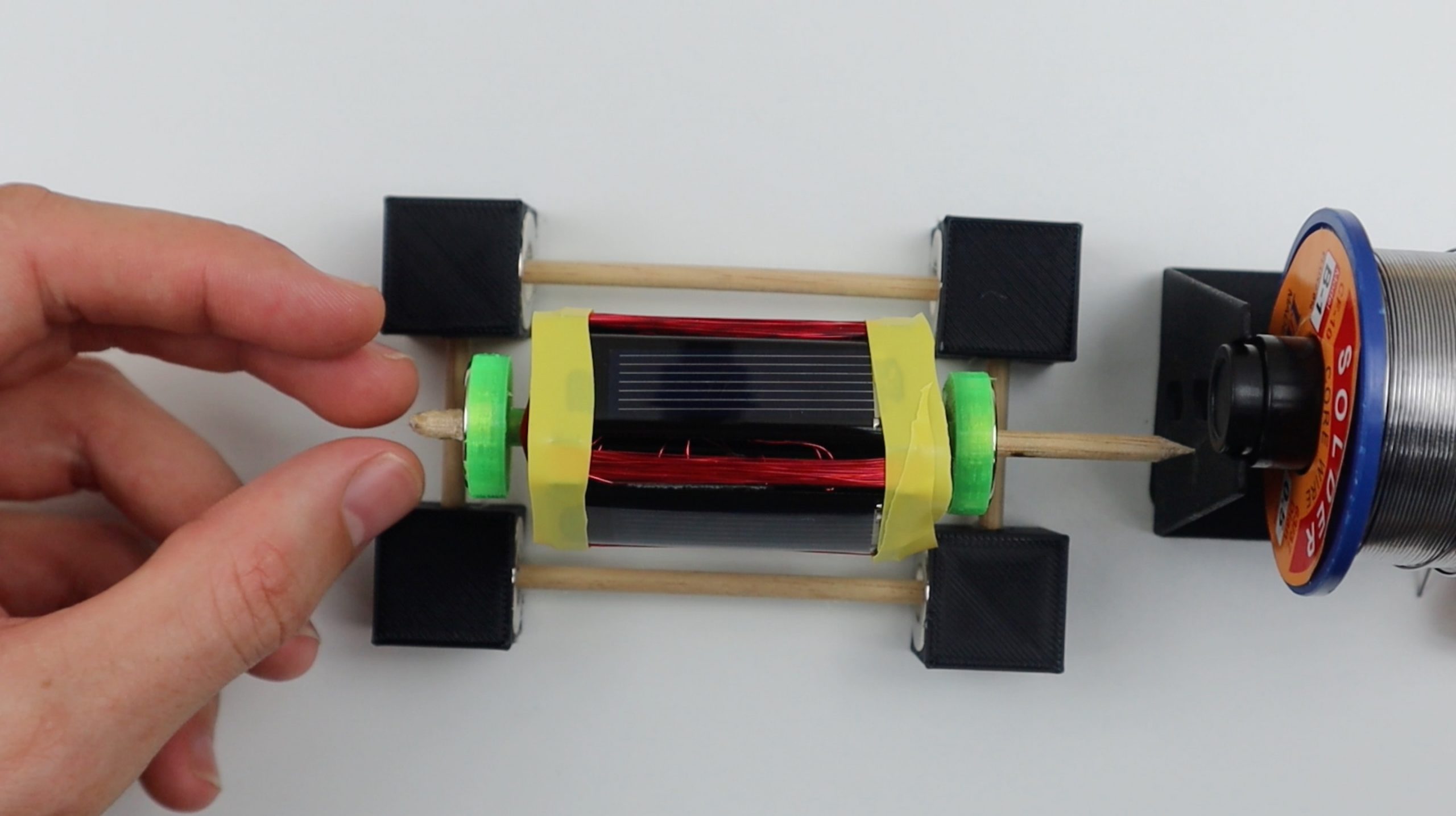
I then used the roll of solder as a temporary reaction point as I needed to measure the floating height of the rotor in order to design a 3D printed reaction arm. You can use the 3D printed one if your components are identical.
Float the rotor on the bearings. You may need to make some adjustments to the positions of the magnets in order to get it to float correctly. The rotor magnets should be almost directly overhead the base magnets but slightly towards the reaction point, so that the magnetic force keeps the rotor pushed up against the reaction point. This step can be quite frustrating to get right. If you’re using different magnets then you’ll need to play around with the base magnet width spacing as well to ensure that you find the “sweet” spot where the rotor is suspended high enough that nothing touches the base and that the base magnets are far enough away from each other that the rotor is stable.
Now you need to check that your panels are wired correctly. Each pair of solar panels will produce a torque in one direction. You need to make sure that both sets are producing this torque in the same direction or your motor won’t turn. Start with one winding directly overhead the stator magnet in a dark area and shine a light onto the top panel (opposite this winding). You should notice the winding gently deflect away from the magnet in one direction. Make a note of the panel and this direction. Then rotate the rotor 90 degrees so that the next winding (half of the second winding) is overhead the stator magnet. Repeat the process with the light and make sure that the rotor deflects in the same direction. If it does, then you’re good to balance the rotor and glue the panels into place. If they deflect in opposite directions then you’ll need to swap the winding connections on one set of panels. This can be done on either set, and you’ll just need to swap the two winding connections around. Don’t change the connections between any of the solar panels or on the second winding. If nothing happens in this step, then you’ll need to check your winding connections again or potentially add more windings to your rotor.
Next check your rotor balancing. Your rotor should turn freely and shouldn’t have any significant heavy spots which it tends to fall to. You most likely won’t be able to get this perfect but you should minimise any heavy spots as far as possible. This can be done by gluing small pieces of solder onto the inside face of the panel opposite to the heavy side until it is properly balanced.
You can then glue the solar panels into place. This may need to be done in conjunction with the rotor balancing step as an iterative process as you’ll change the balancing by adding glue and removing the tape, but this will also limit your access to the back of the panels to add more solder.
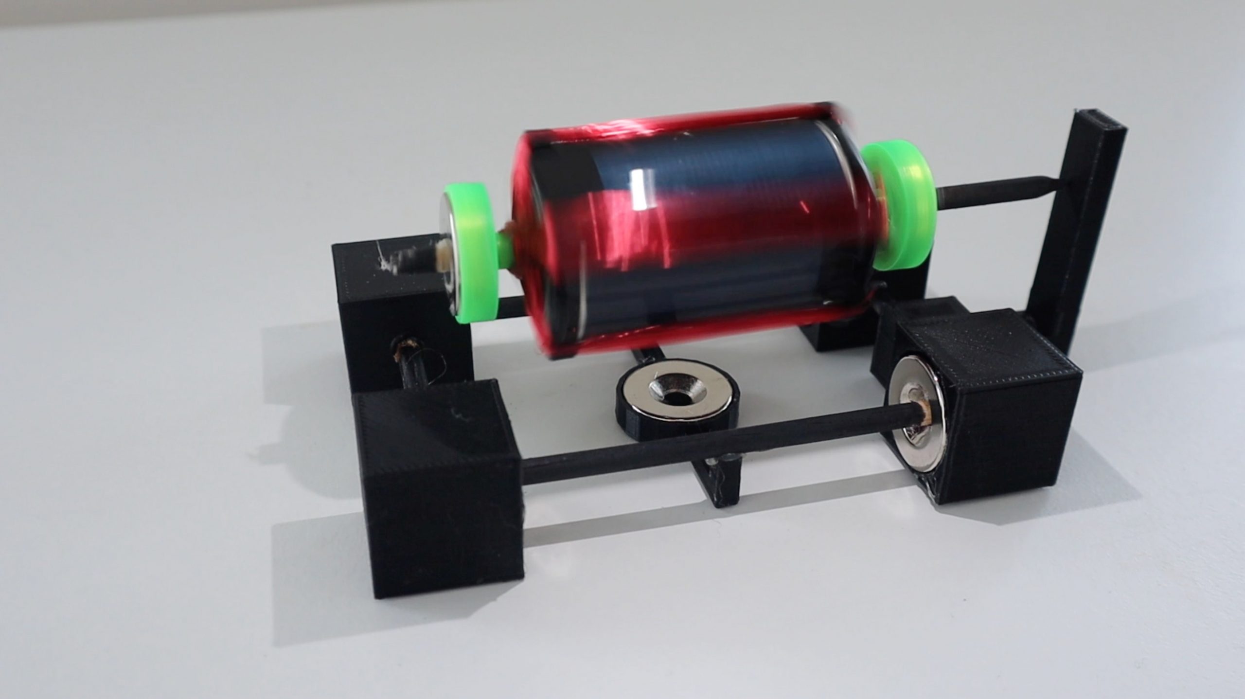
Finally, glue the rotor reaction support into place and glue the remaining connections on the base if you haven’t done so already. You can also glue your stator magnet into the magnet holder and onto the base in order to make the whole motor portable.
You should now be able to run your Mendocino motor. The motor will run best in a dark area with a directional light source shining down on it at about 30 degrees off vertical. You’ll need to play around with the light source a bit to get it into the correct position to produce the most torque and therefore the highest speed. You may also need to adjust the balancing again if it turns too quickly and becomes unstable.
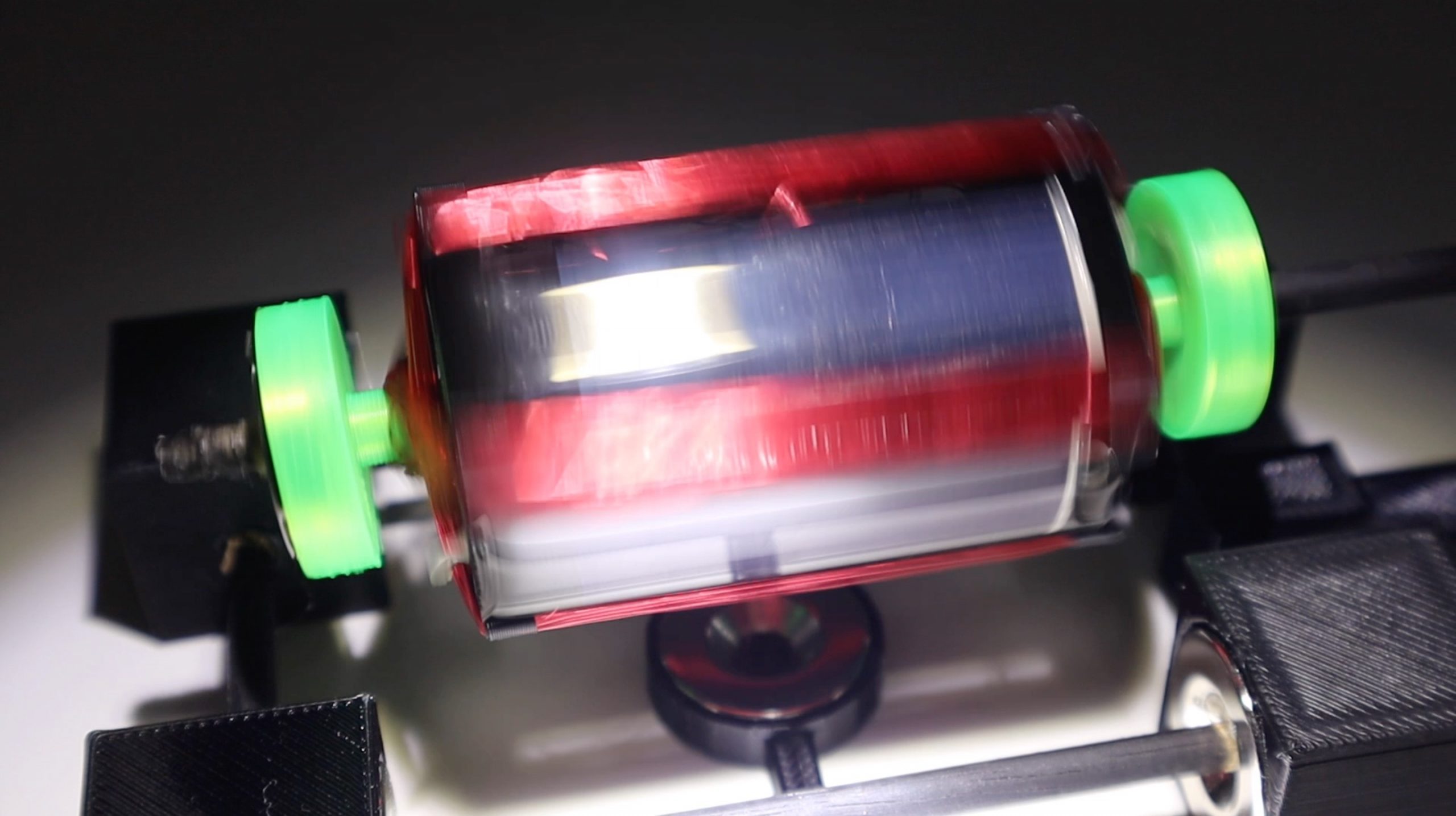
The balancing of my Mendocino motor in the video is not great at lower speeds and could do with a bit more time spent adjusting it.