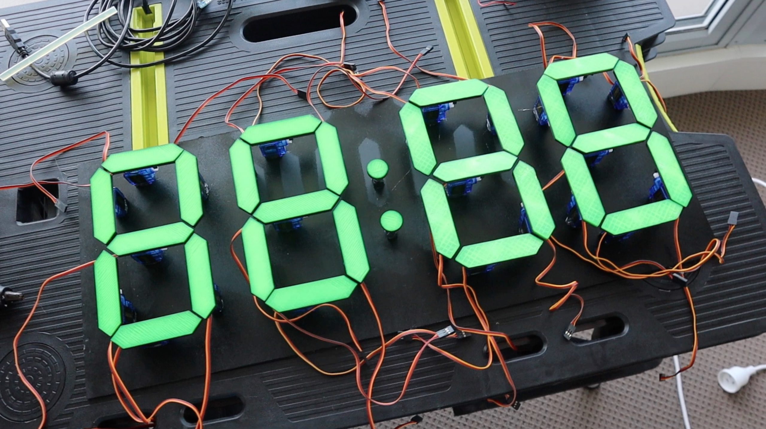
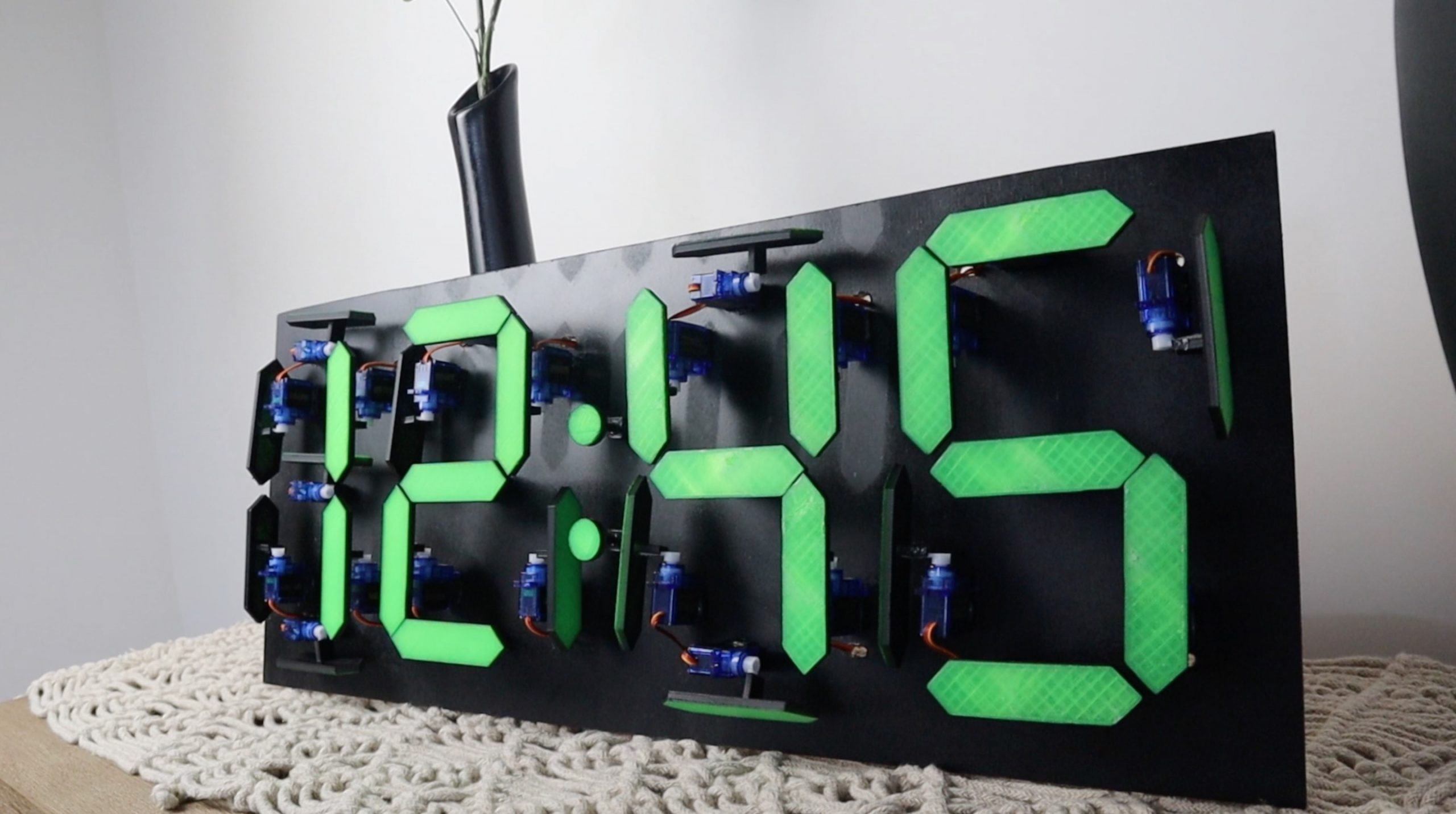
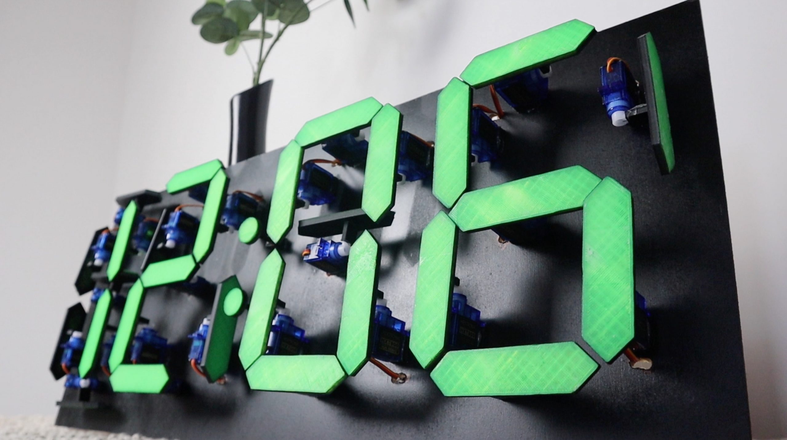
I built a countdown timer a couple of months ago using a two digit mechanical 7 segment display which was driven by 14 servos and an Arduino Mega. It came out quite well and a number of people suggested doubling up on the display to build a clock. The only problem was that the Arduino was already running short on PWM IO and I needed to double up on the outputs. Fortunately, someone pointed me in the direction of these PCA9685 16 channel PWM drivers, so I used them and a DS1302 real time clock module to build a mechanical 7 segment display clock which uses 28 servos and is now driven using an Arduino Uno.
Here’s a video of the build and the clock in operation, else read on for the full step by step instructions, code and 3D print downloads.
What You Need To Build Your Own Mechanical 7 Segment Display Clock
- Arduino Uno – Buy Here
- DS1302 Clock Module – Buy Here
- 2 x PCA9685 16Ch Servo Drivers – Buy Here
- 28 x Micro Servos – Buy Here
- Ribbon Cable – Buy Here
- Male Pin Header Strips – Buy Here
- Female Pin Header Strips – Buy Here
- 3mm MDF – Buy Here
- Black Spray Paint – Buy Here
- 5V 5A Battery Elimination Circuit – Buy Here
- 12V Power Supply – Buy Here
You’ll also need to 3D print some components. If you don’t have a 3D printer and you enjoy making things, you should definitely consider getting one. The one below is affordable and produces pretty high quality prints for the price. If you don’t want to get a 3D printer yet, there are a couple of online services which will print components for you and ship them to you.
How To Build Your Clock
3D Print The Components
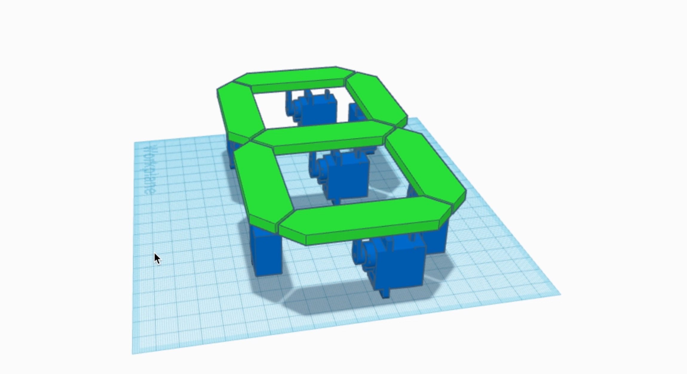
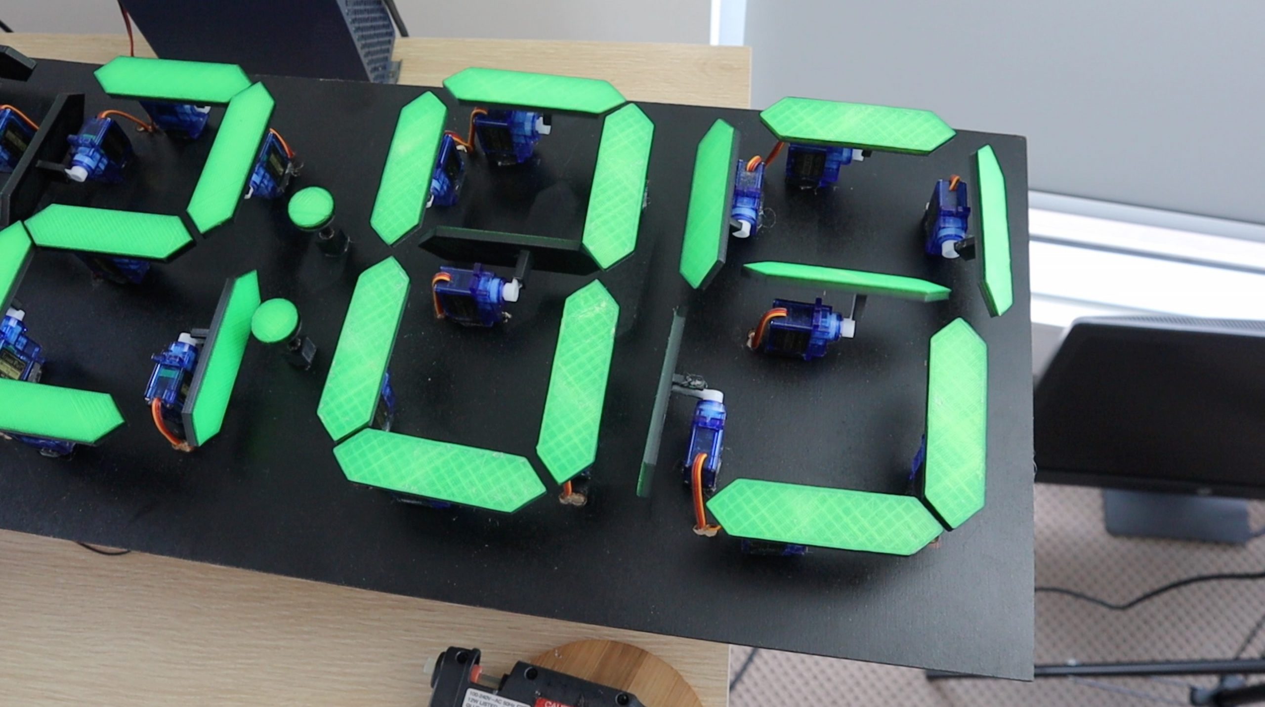
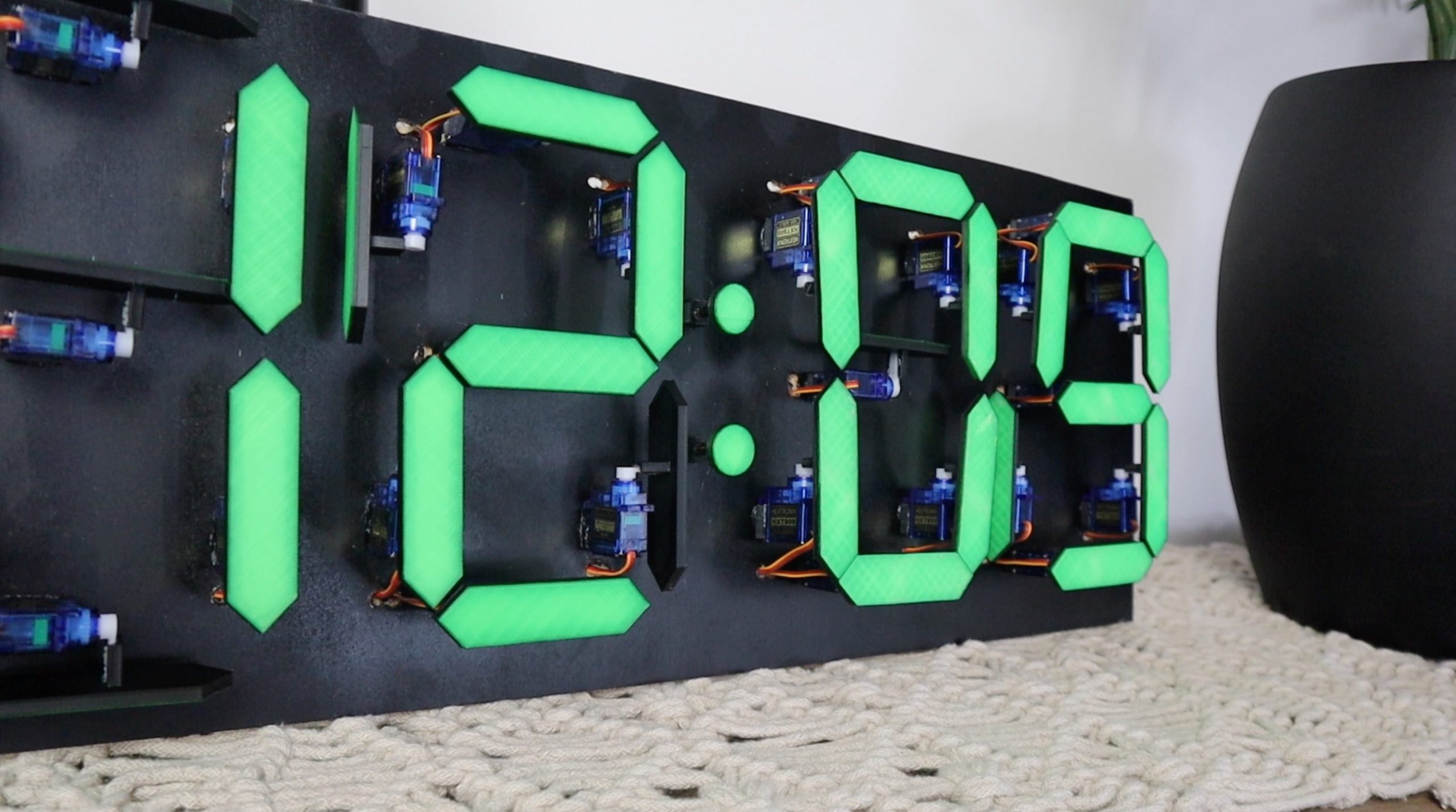
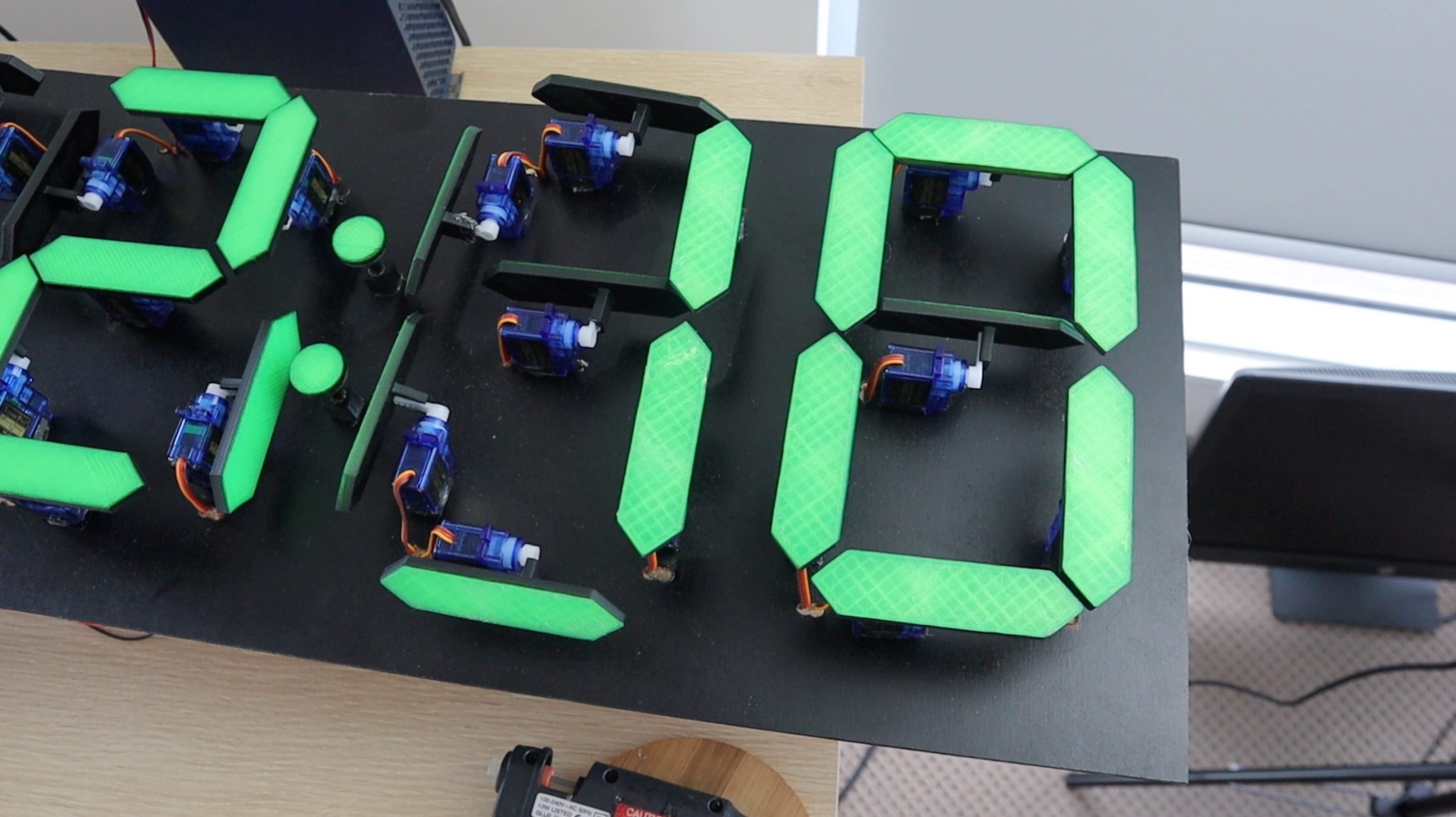
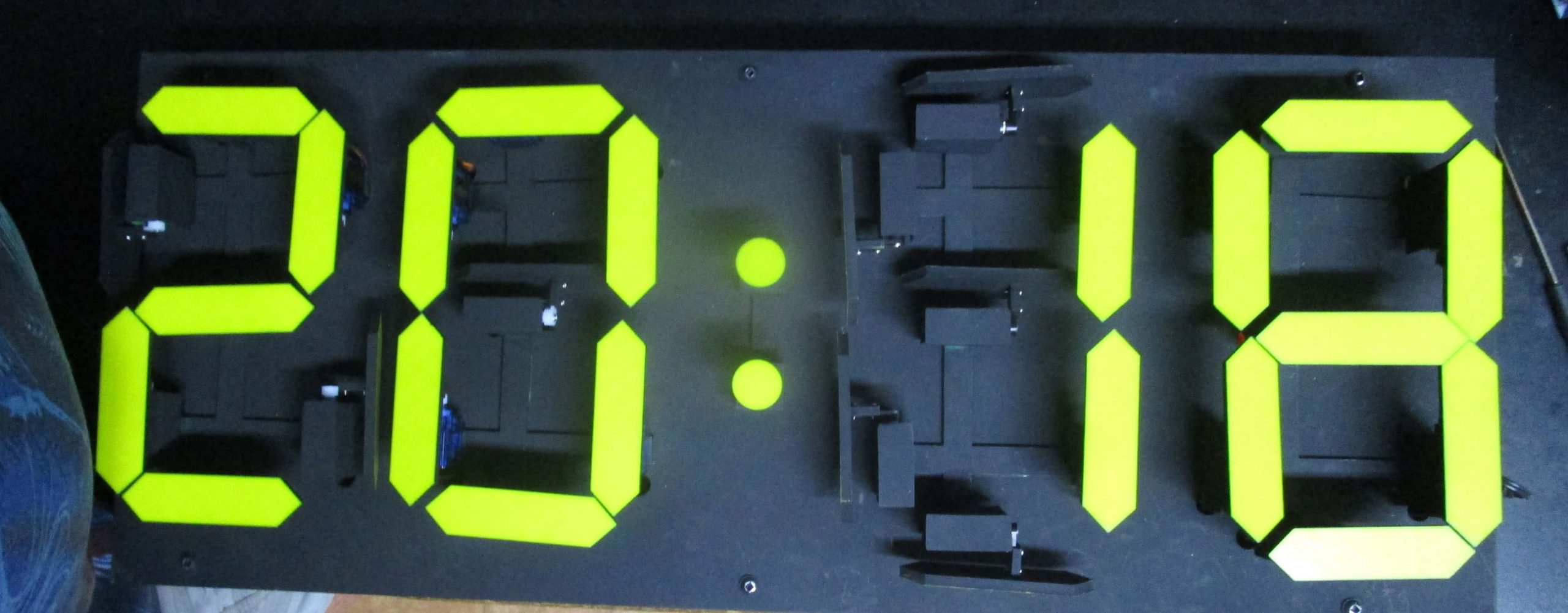
I started off by designing an individual 7 segment display numeral which could be actuated using a micro servo for each segment. The micro servos move each segment vertically when on and 90 degrees to the side when off.
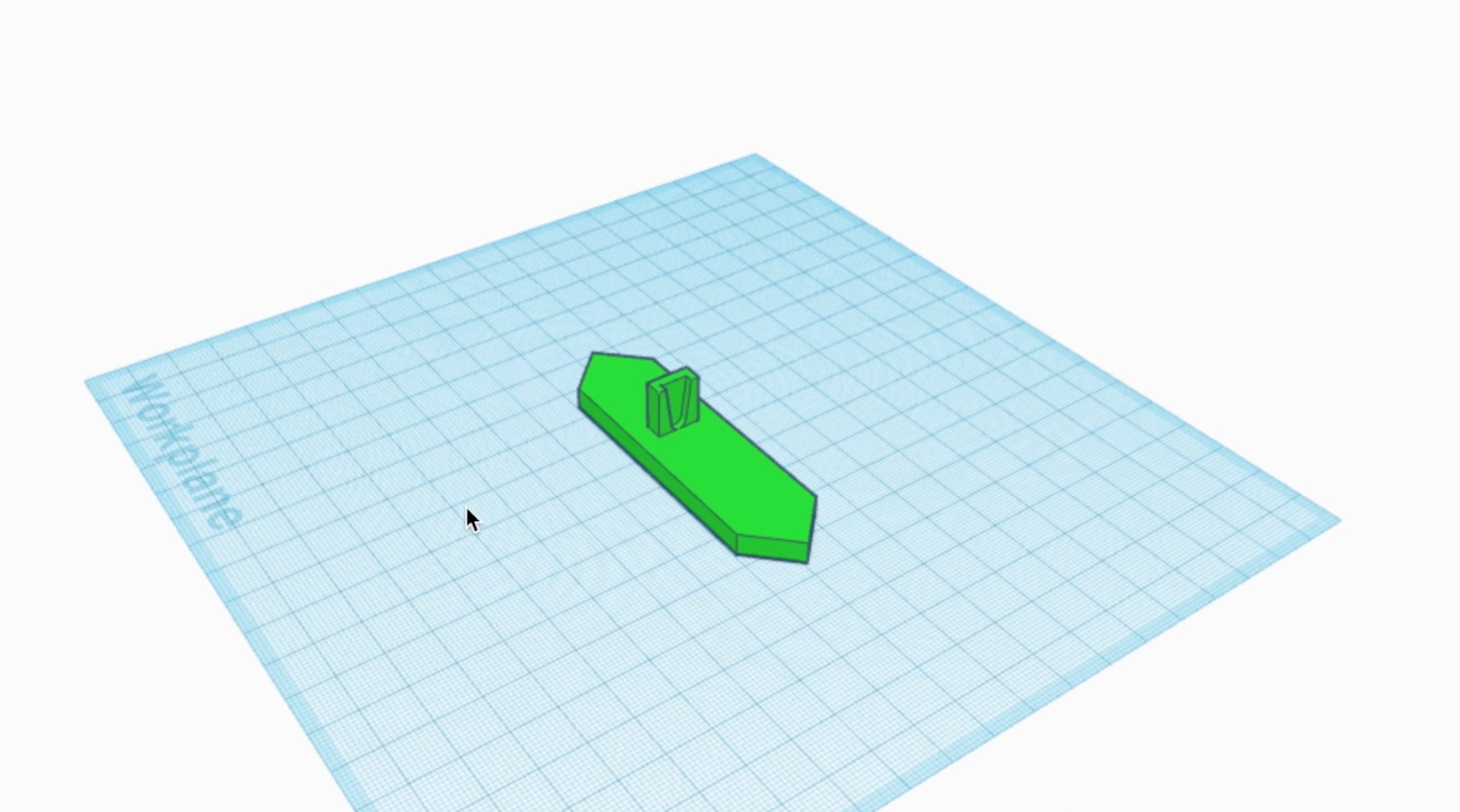
The segments are designed to glue straight onto the standard servo arm so that no additional hardware is required.
Download The 3D Print Files – 7 Segment Clock 3D Print Files
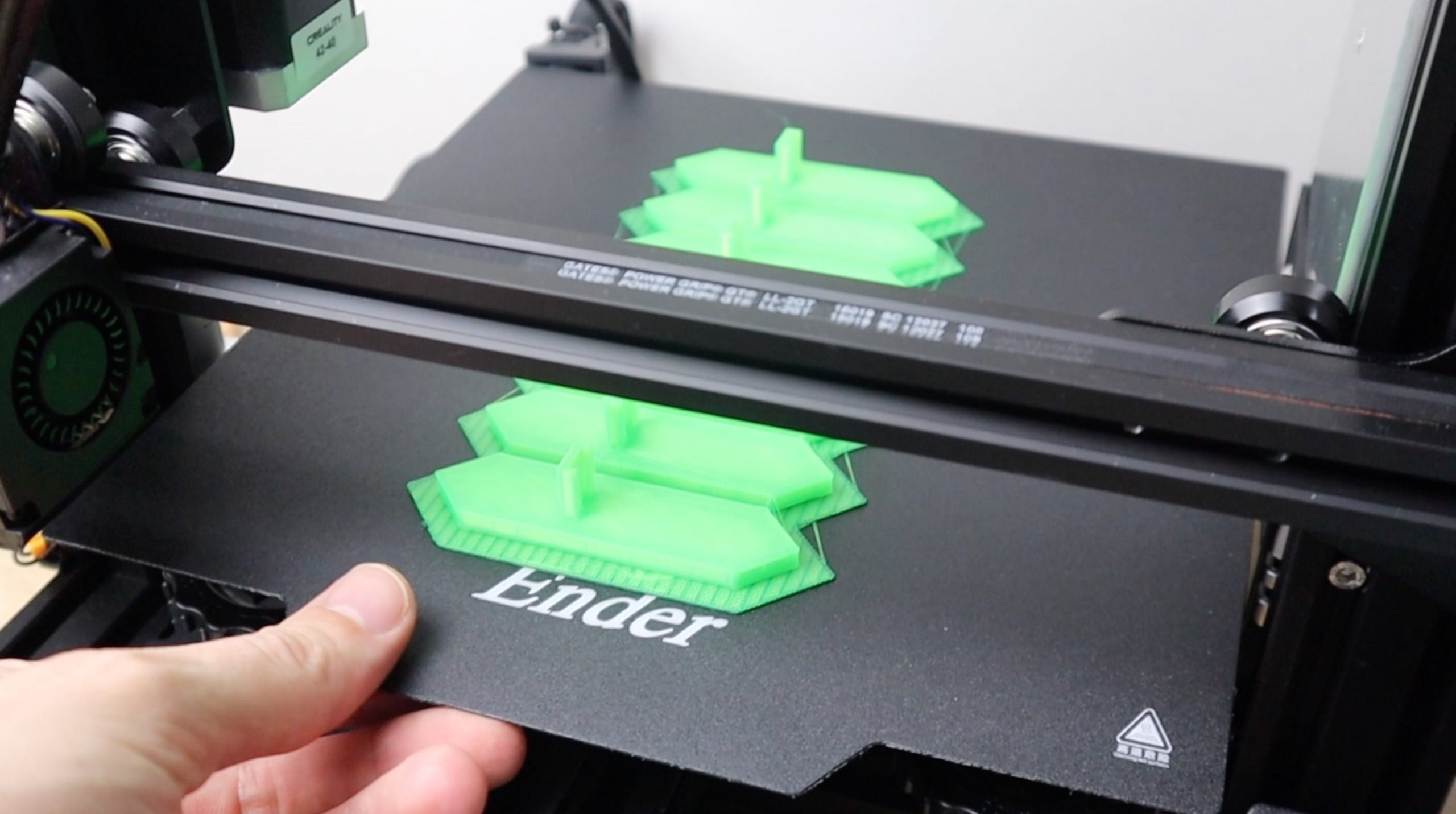
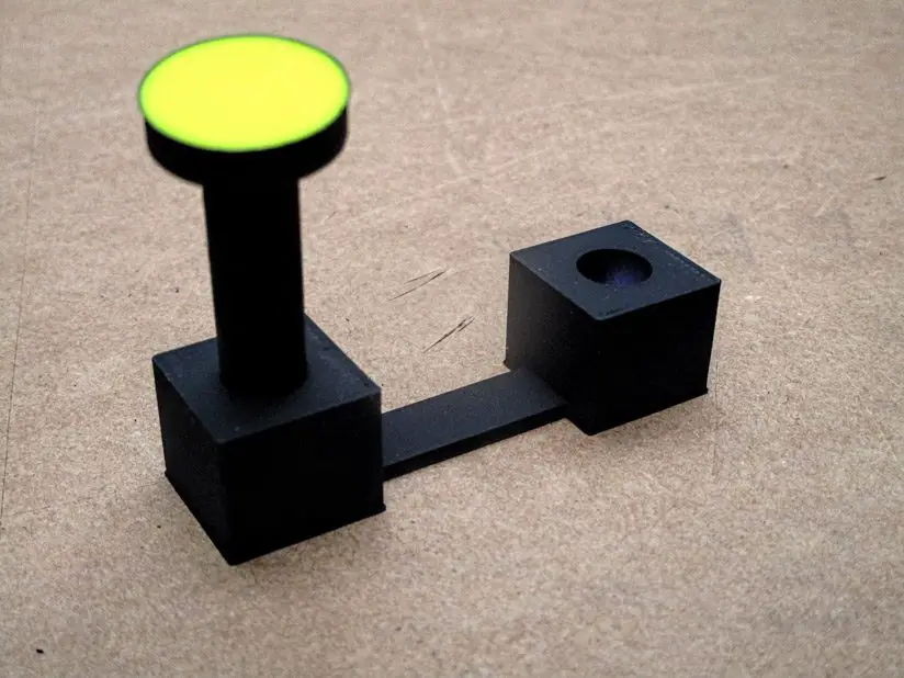
You’ll need to 3D print the 28 segments using a translucent green PLA with 15% infill. You’ll also need to print out the 28 base blocks to support the servos as well as the two dots for the centre and their bases. You could use any brightly coloured PLA for the segments, red would create a more traditional looking 7 segment display. Use black PLA for the spacer blocks and bases so that they’re not visible on the black background.
Solder The Wiring Harnesses
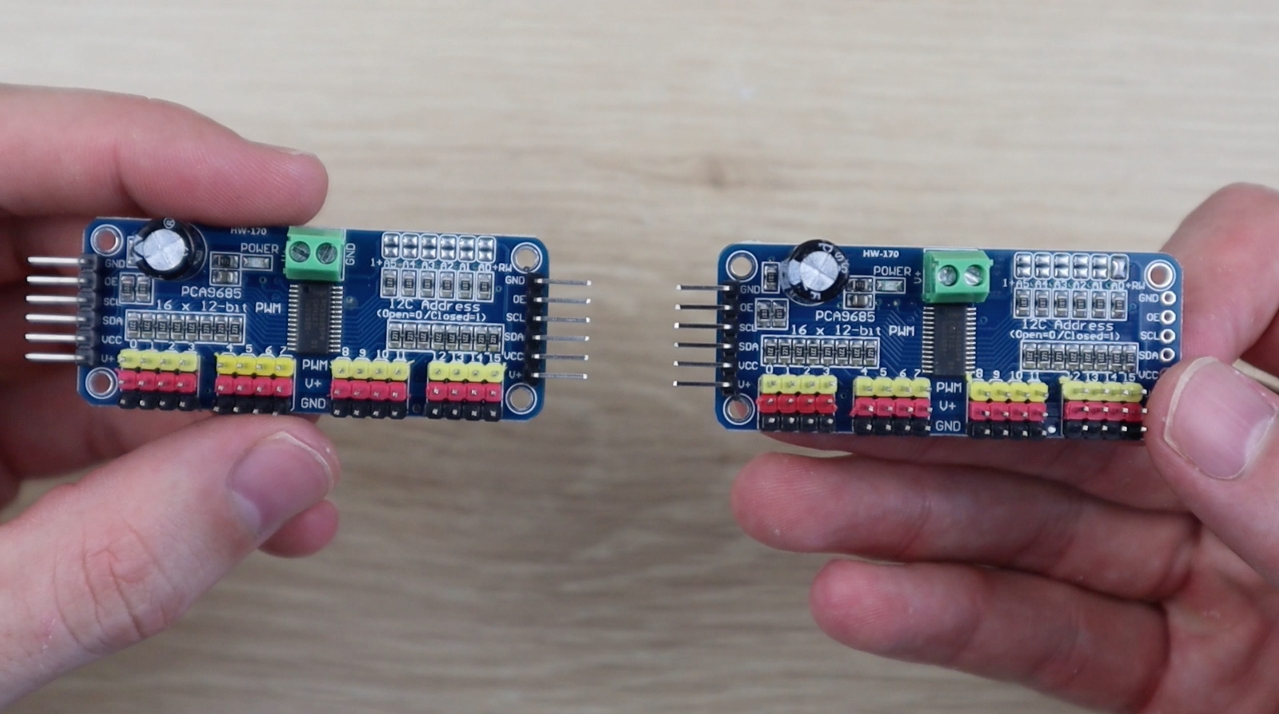
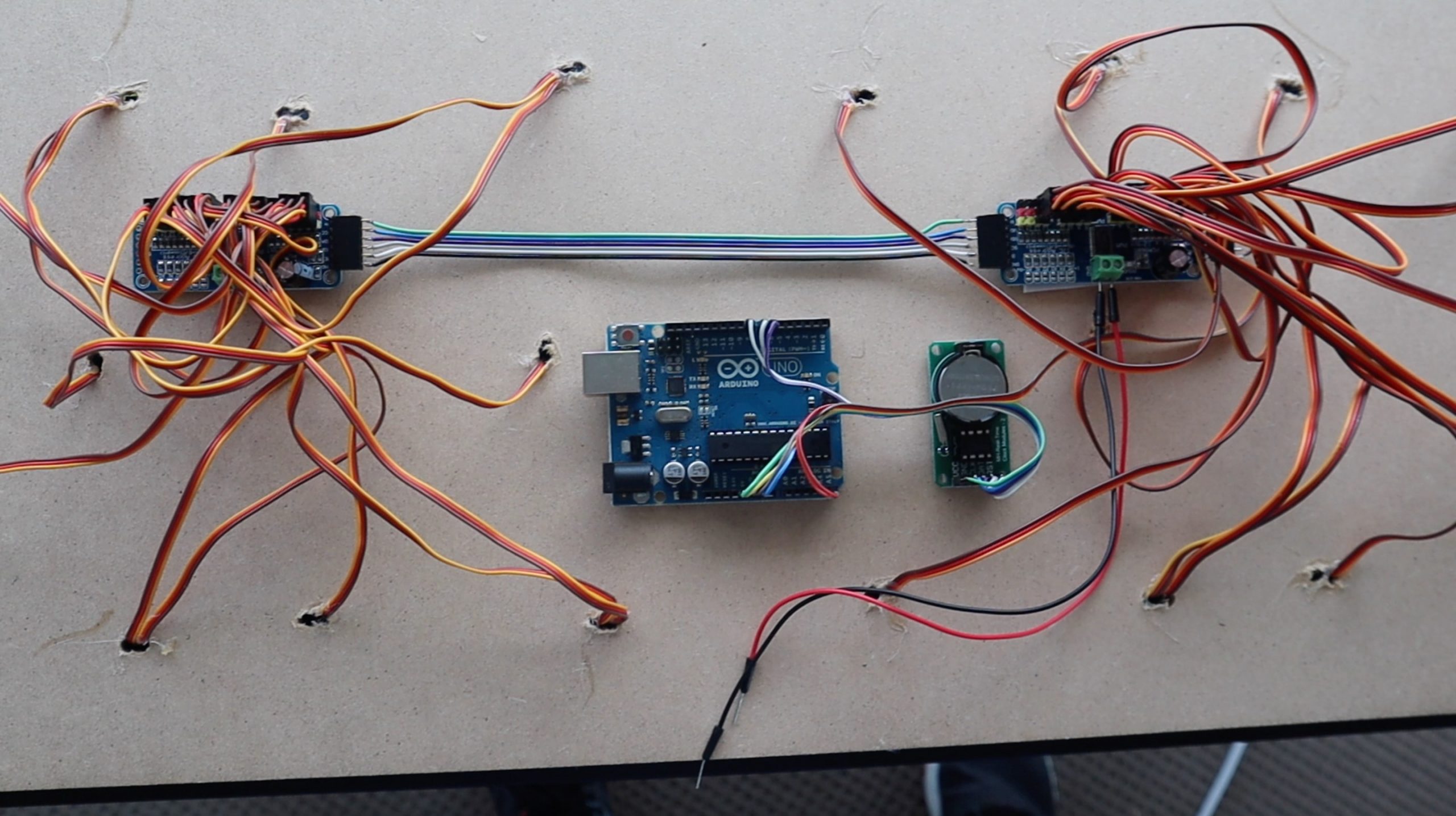
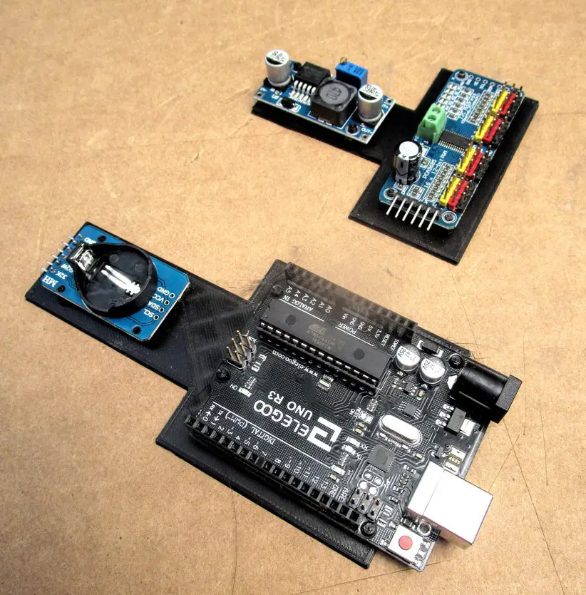
I used two PCA9685 16 channel PWM drivers which allow you to control up to 16 servos on each board and chain up to 62 boards together over an I2C interface, which uses only two IO pins on your Arduino. This means that you could theoretically independently control up to 992 servos with just two IO pins. We’re going to be using one for the two hour digits and one for the two minute digits.
To chain the two together, you need to first add a pin header to the other side of the first board and then change the address on the second board so that it’s uniquely identified.
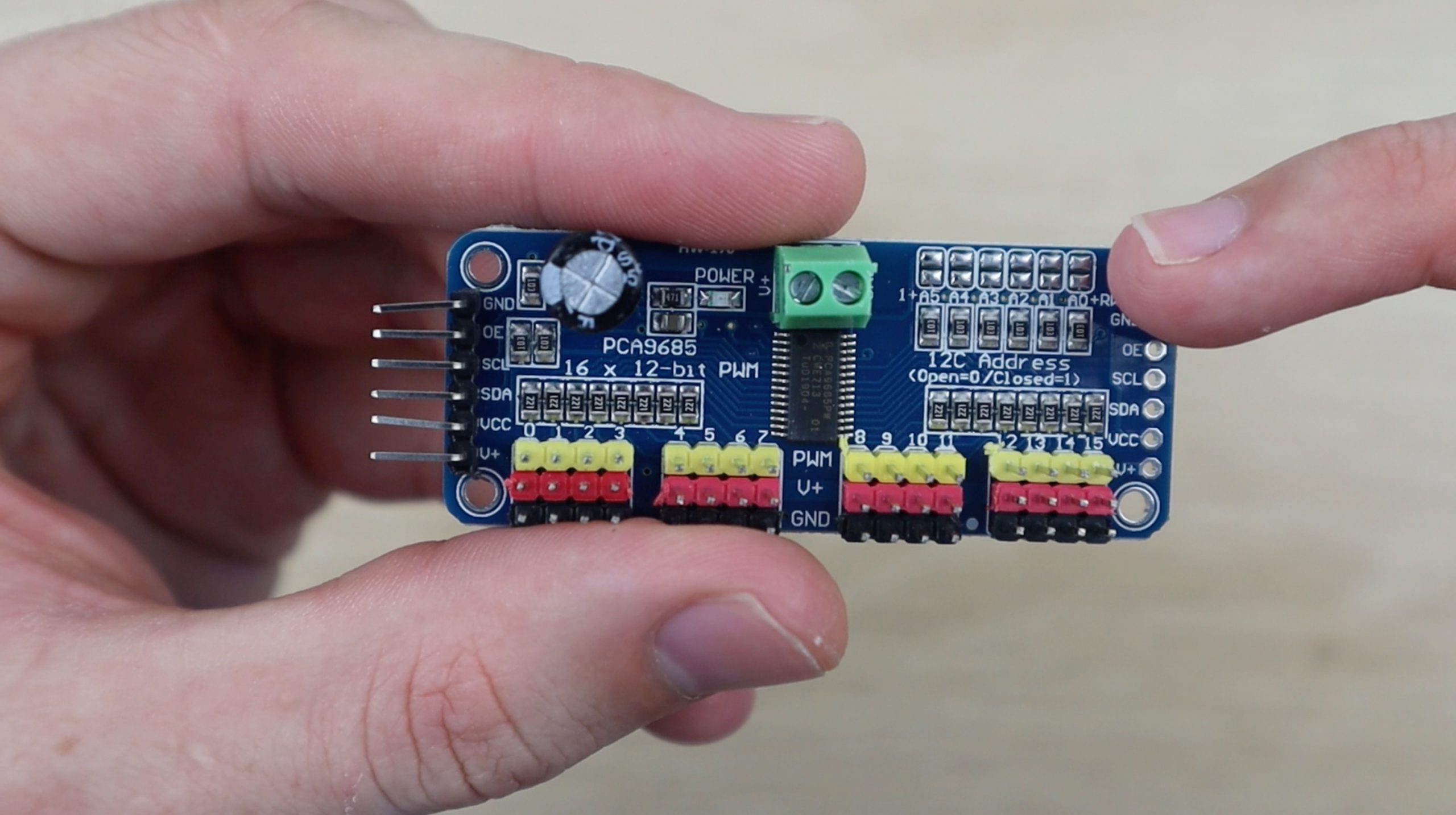
This is done by bridging the small terminals on the top right of the board. They work like dip switches, allowing you to set a different address for each board. You only need to bridge one set of terminals on the far right for this project.
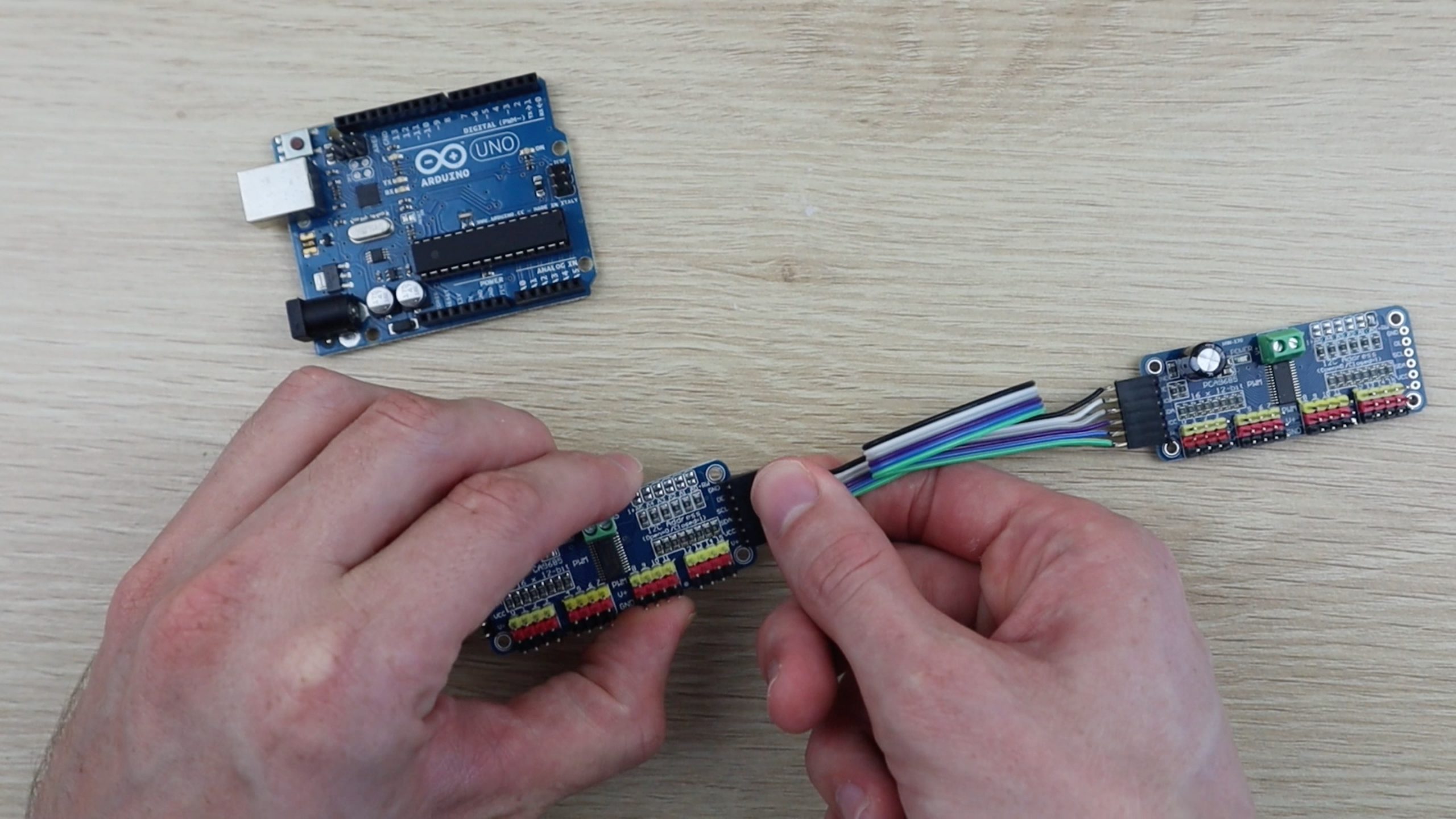
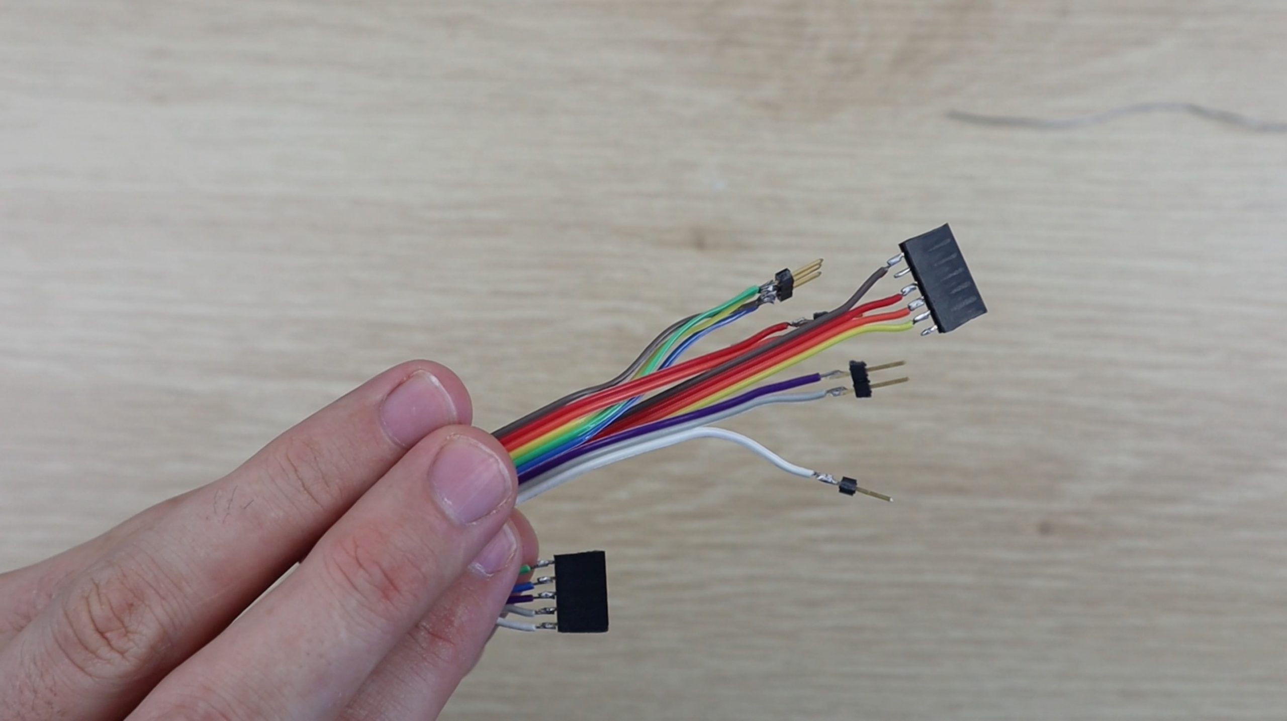
Once you’ve added the header strip and changed the address on the second board, you’ll need to make up the cable to chain the two together.
You’ll also need a wiring harness to connect these two boards to the Arduino along with the clock module.
Here’s the circuit diagram:
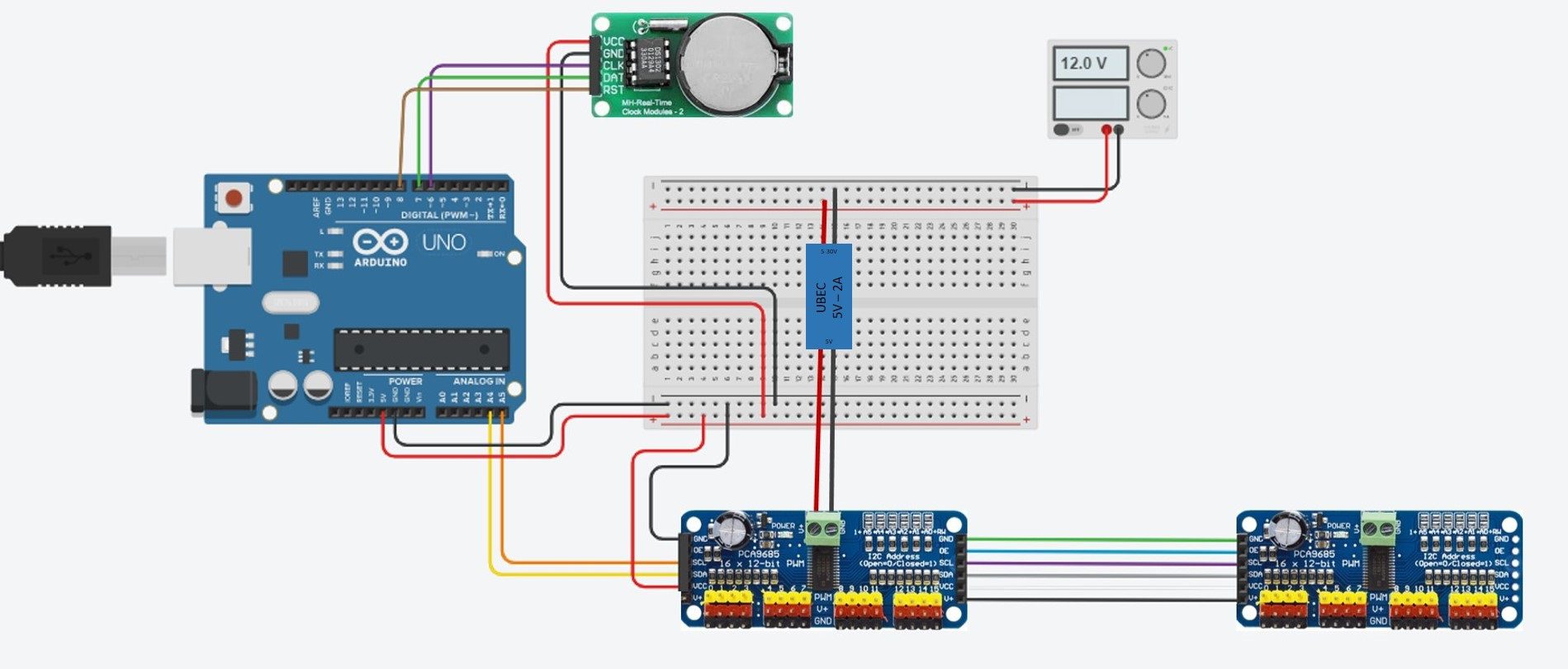
You’ll need to connect both the clock and the servo control boards to your Arduino’s GND and 5V pins to supply them with power. You’ll also need to connect the I2C interface on the servo control boards to your Arduino pins A4 and A5 (SDA and SCL respectively). Note that you’ll only connect one board to the Arduino, the second board is connected to the first board and will access the Arduino through this connection. Lastly, you’ll need to connect your real time clock module pins CLK, DAT & RST to pins 6, 7 & 8 respectively.
Power is supplied to the servos through the terminals on the servo driver boards. You’ll need to connect your 5V 5A BEC to your 12V power supply and then connect the leads to the terminals on one of the boards. You don’t need to connect both, if you’ve connected all of the pins between the two boards together then power will be supplied across your connection as well. You’ll also need to power your Arduino, this can be done from the same 12V power supply.
Assemble The Clock Display
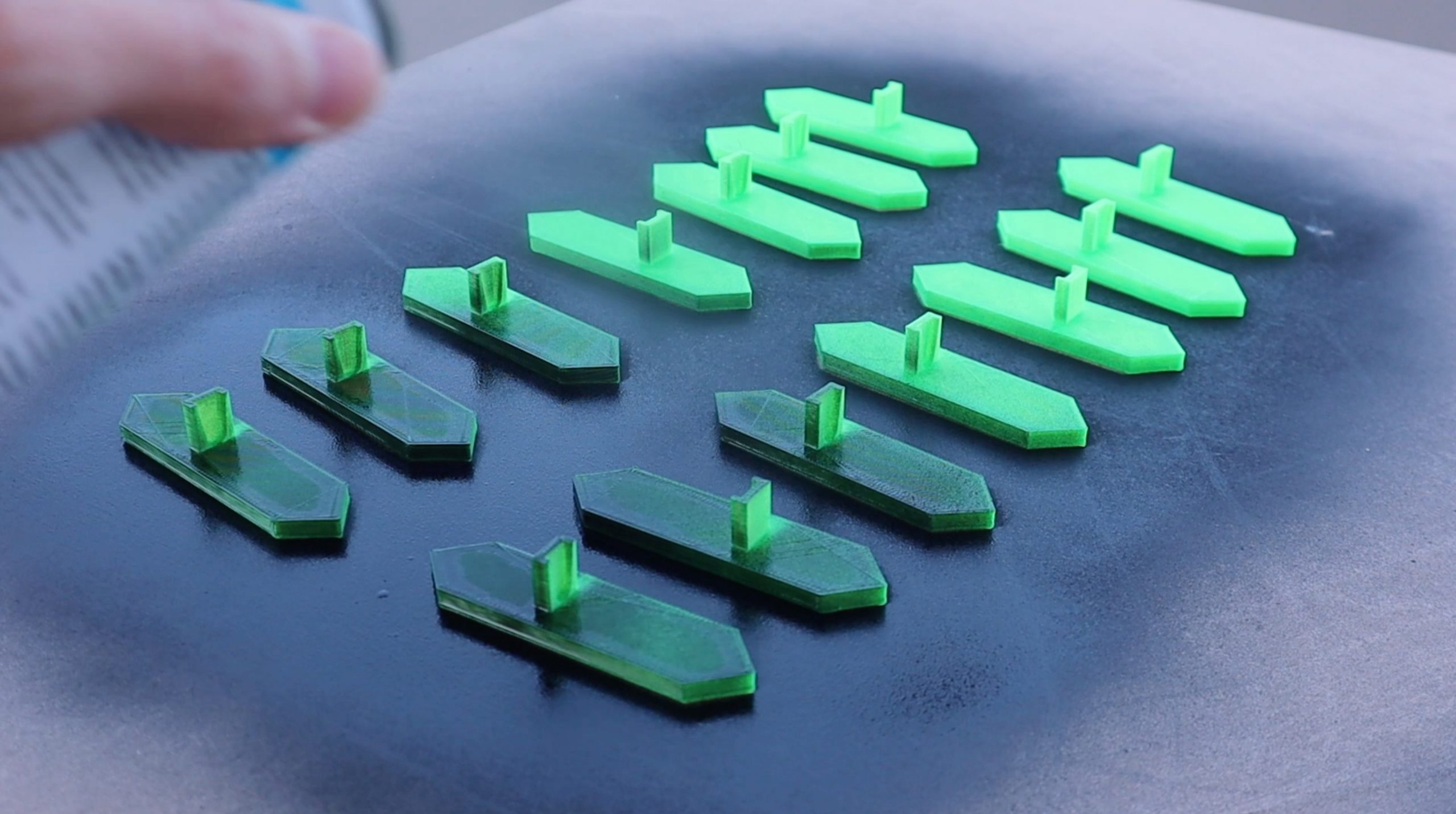
Once the 3D printed segments are complete, you’ll need to spray the back and sides of the segments black to match the background so that they’re less visible when turned away. If you leave them green then you’re still going to land up with a thin visible line when the segment is turned 90 degrees. Also spray the back and sides of the dots so they’re less visible from the side.
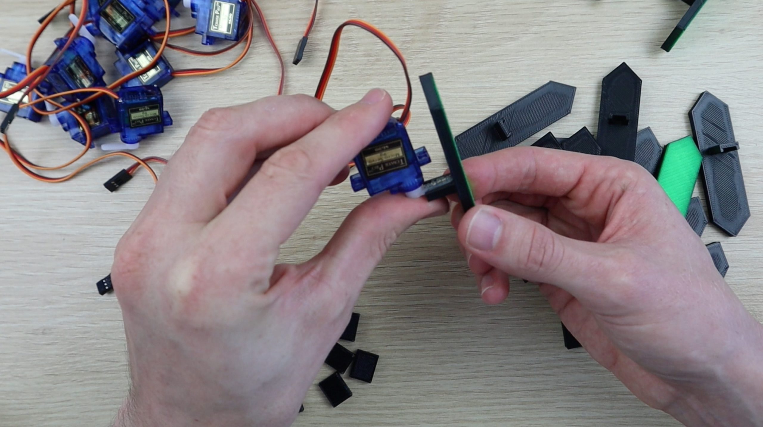
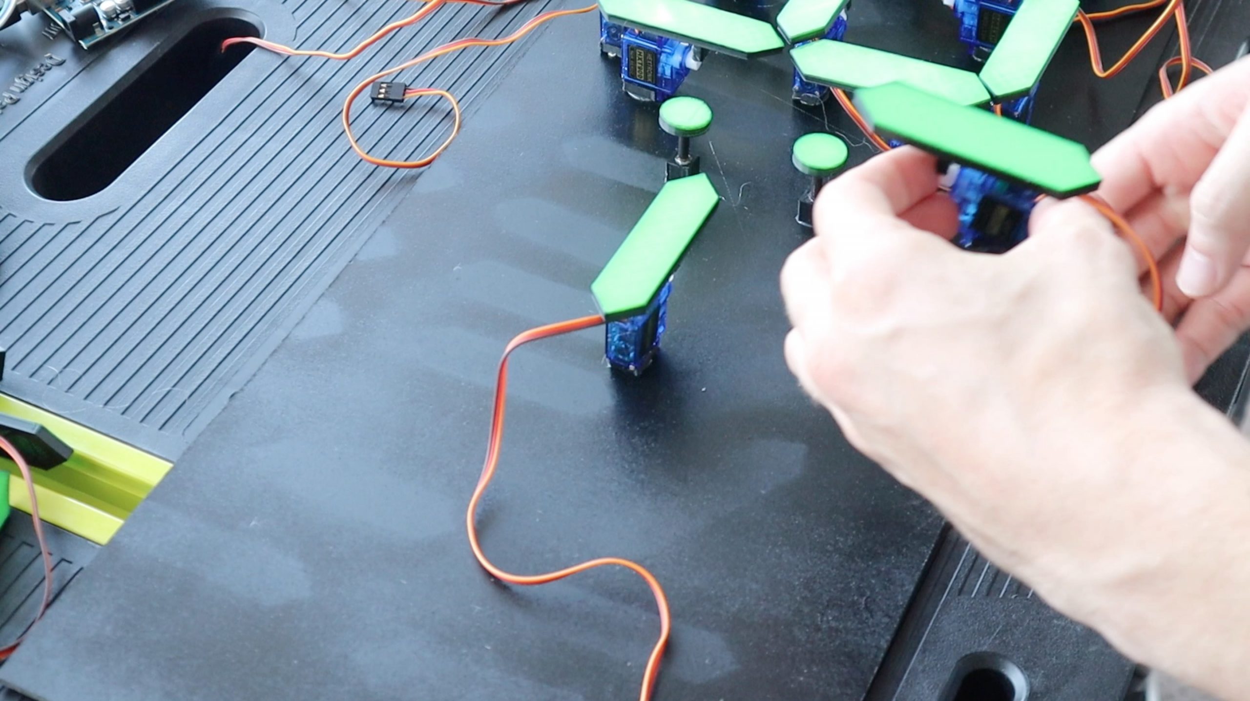
Next glue the segments onto the servo arms using hot melt glue. It’s easiest to put the arms onto the servos and then glue the segment onto the servo and arm assembly, this also allows you to check that you glue it on straight.
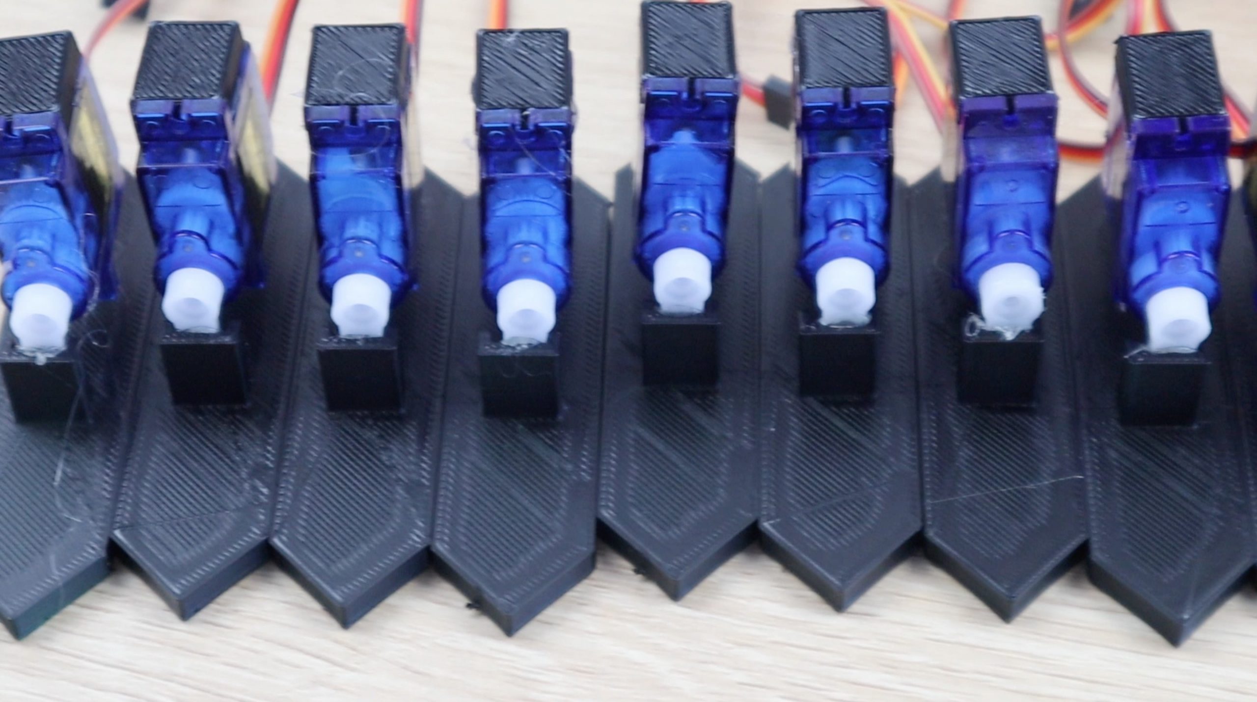
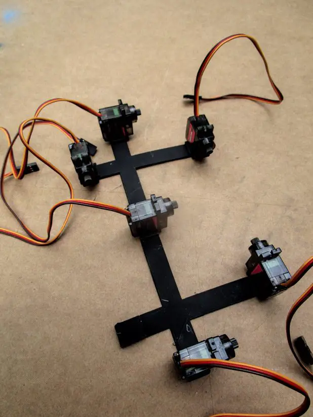
You’ll also need to glue the small 3D printed spacer blocks to the bottom of each servo as well, these help the servo to stand upright when you glue them onto the back board.
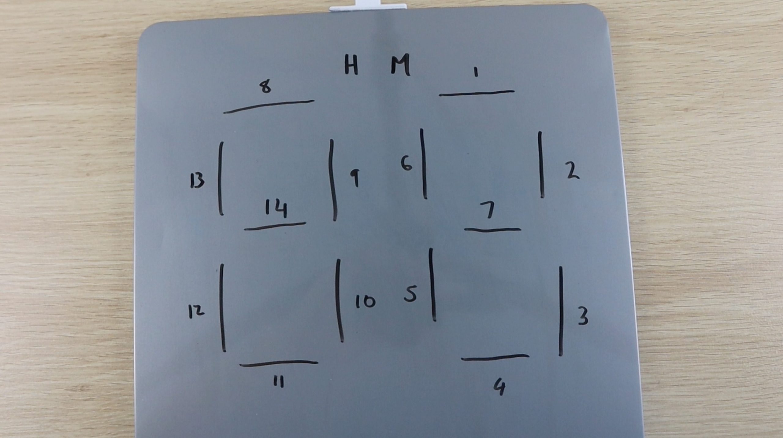
I numbered each segment to keep track of them in the code. I started with the top segment in the units digit being 1 and worked around to the tens digit for all fourteen segments. They are connected to each driver board in this order as well, although the driver board numbering starts from zero. I duplicated this numbering for each of the hour and minute boards. If you’re struggling to keep track of each servo, write these numbers onto the leads as well.
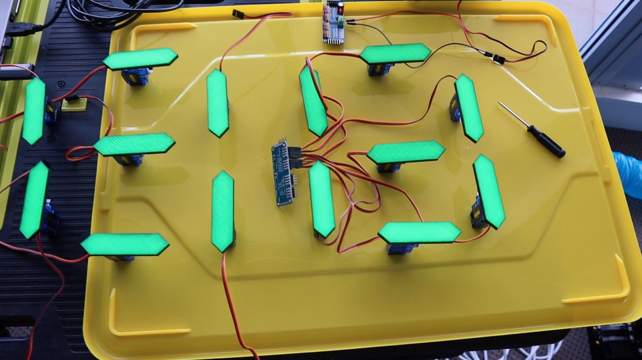
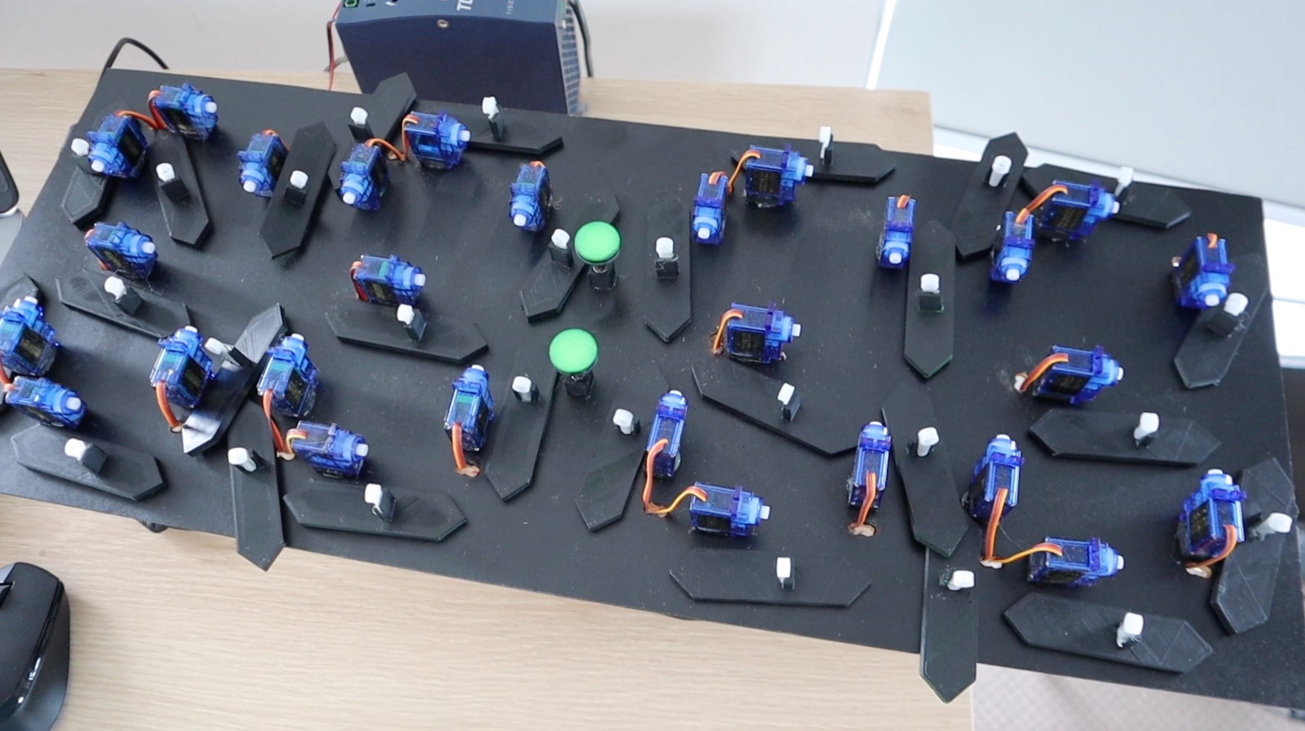
Before gluing the digits onto the back board, I laid them out on a flat surface to test them. This allowed them to move without the fear of them moving in the wrong direction or too far and bumping into each other, which may damage the segments or strip the gears on the servos.
Once I was happy with the movement of the digits, I got to work on the board.
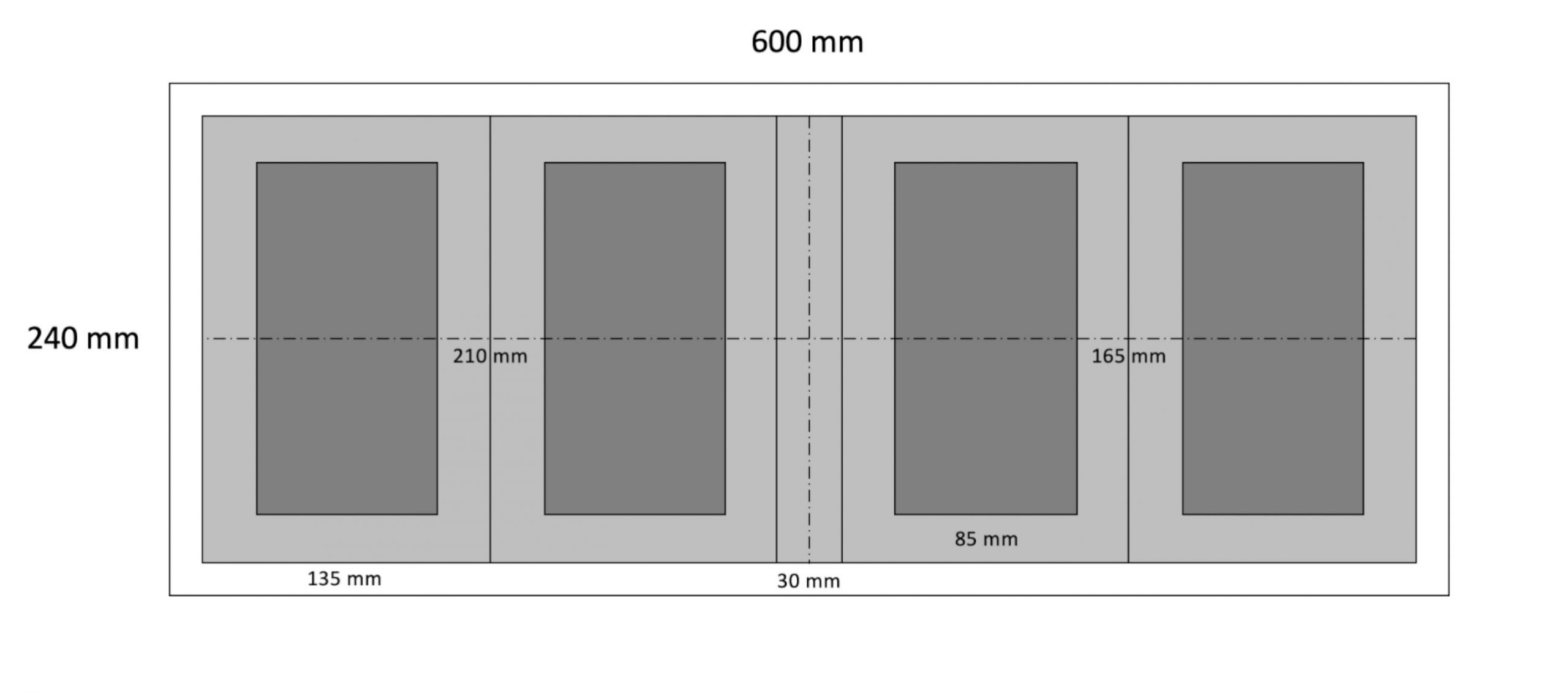
You’ll need a back board which is at least 600mm (24″) long by 240mm (10″) high. The light grey larger boxes are the areas in which the segments move when they move out of the way, these need to be at least 210mm (8 1/4″) by 135mm (5 1/3″) so that adjacent segments don’t touch when they both move outwards to their off positions. The inner darker rectangles are the centre lines for the 6 servos which make up the outside of each digit. Lastly, leave 30mm between the inner digits for the dots.
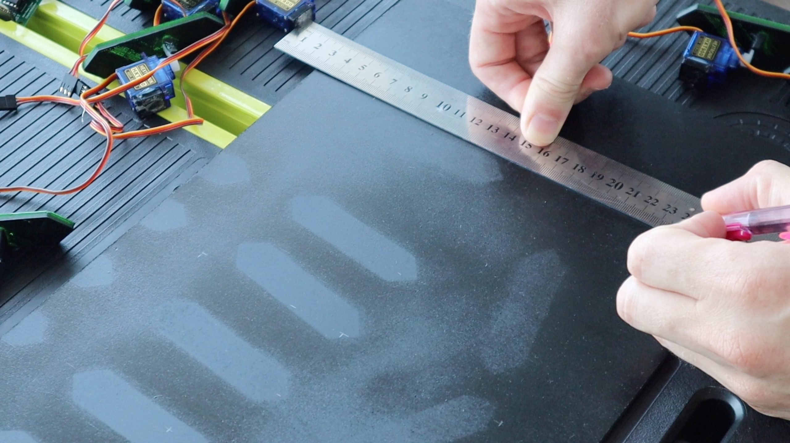
Measure and cut the back board from a piece of 3mm MDF and spray it black as well.
Mark the segment positions on the back board as per the diagram and then start gluing them in place. The dots are supported on their bases using short sections of 4mm dowel or kebab sticks. Measure and cut the sticks such that the dots are at the same level as the segments once they are glued onto the back board.
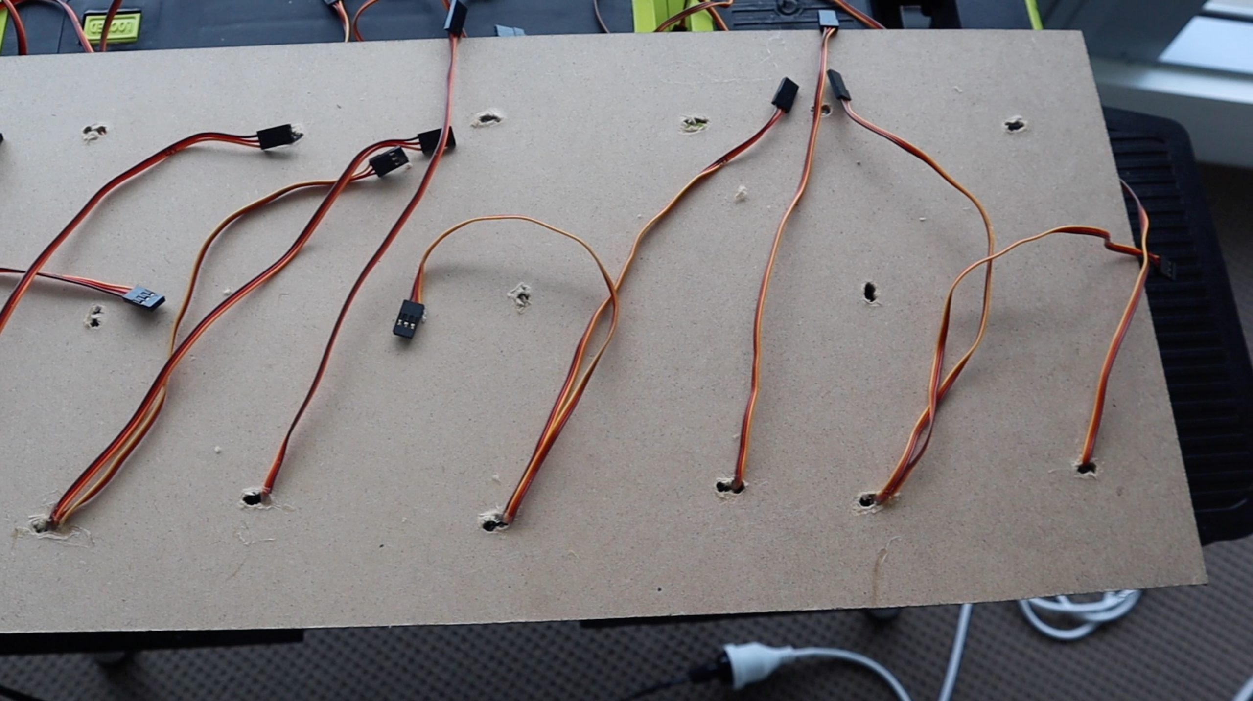
Once the digits are done, you’ll need to hide the wiring. Drill holes through to the back of the board near each servo to feed the servo wires through, this is when it helps to have numbered the leads beforehand. Put a small drop of glue onto each to keep them in place.
Stick the four electronics boards onto the back of the clock using double sided tape. You could also mount them with screws, just make sure that the screws don’t go all the way through the MDF to the other side.
I removed the arms from the servos before loading the final version of the software so that I could make small adjustments to the upright positions without worrying about them hitting each other. It’s a good idea to remove the arms from your servos and keep them off until you’ve powered your board up at least once and got the servos all in their On positions, 88:88 displayed. This way you can put them back into place without worrying about them moving and bumping into each other.
Uploading The Sketch
Now that you’re done building your clock, lets have a look at the code:
//Michael Klements
//The DIY Life
//8 February 2020

#include <virtuabotixRTC.h>               //Include library for clock module
#include <Adafruit_PWMServoDriver.h>      //Include library for servo driver

Adafruit_PWMServoDriver pwmH = Adafruit_PWMServoDriver(0x40);    //Create an object of Hour driver
Adafruit_PWMServoDriver pwmM = Adafruit_PWMServoDriver(0x41);    //Create an object of Minute driver (A0 Address Jumper)

int servoFrequency = 50;      //Set servo operating frequency

int segmentHOn[14] = {385,375,385,375,382,375,354,367,375,385,375,368,371,375};   //On positions for each Hour servo
int segmentMOn[14] = {382,395,378,315,375,340,345,380,385,365,290,365,315,365};   //On positions for each Minute servo
int segmentHOff[14] = {200,200,550,480,200,520,200,200,200,480,550,200,515,200};    //Off positions for each Hour servo
int segmentMOff[14] = {200,200,550,440,200,480,200,200,200,550,450,200,430,200};    //Off positions for each Minute servo
int digits[10][7] = {{1,1,1,1,1,1,0},{0,1,1,0,0,0,0},{1,1,0,1,1,0,1},{1,1,1,1,0,0,1},{0,1,1,0,0,1,1},
                     {1,0,1,1,0,1,1},{1,0,1,1,1,1,1},{1,1,1,0,0,0,0},{1,1,1,1,1,1,1},{1,1,1,1,0,1,1}};    //Position values for each digit

virtuabotixRTC myRTC(6, 7, 8);    //Create a clock object attached to pins 6, 7, 8 - CLK, DAT, RST
int hourTens = 0;                 //Create variables to store each 7 segment display numeral
int hourUnits = 0;
int minuteTens = 0;
int minuteUnits = 0;

int prevHourTens = 8;           //Create variables to store the previous numeral displayed on each
int prevHourUnits = 8;          //This is required to move the segments adjacent to the middle ones out of the way when they move
int prevMinuteTens = 8;
int prevMinuteUnits = 8;

int midOffset = 100;            //Amount by which adjacent segments to the middle move away when required

void setup()
{
  pwmH.begin();                             //Start each board
  pwmM.begin();
  pwmH.setOscillatorFrequency(27000000);    //Set the PWM oscillator frequency, used for fine calibration
  pwmM.setOscillatorFrequency(27000000);
  pwmH.setPWMFreq(servoFrequency);          //Set the servo operating frequency
  pwmM.setPWMFreq(servoFrequency);
  //myRTC.setDS1302Time(00, 10, 16, 5, 8, 4, 2020);        //Only required once to reset the clock time
  for(int i=0 ; i<=13 ; i++)    //Set all of the servos to on or up (88:88 displayed)
  {
    pwmH.setPWM(i, 0, segmentHOn[i]);
    delay(10);
    pwmM.setPWM(i, 0, segmentMOn[i]);
    delay(10);
  }
  delay(2000);
}

void loop()
{
  myRTC.updateTime();                 //Update the time
  int temp = myRTC.hours;             //Get the hours and save to variable temp
  hourTens = temp / 10;               //Split hours into two digits, tens and units
  hourUnits = temp % 10;
  temp = myRTC.minutes;               //Get the minutes and save to variable temp
  minuteTens = temp / 10;             //Split minutes into two digits, tens and units
  minuteUnits = temp % 10;

  if(minuteUnits != prevMinuteUnits)  //If minute units has changed, update display
    updateDisplay();

  prevHourTens = hourTens;            //Update previous displayed numerals
  prevHourUnits = hourUnits;
  prevMinuteTens = minuteTens;
  prevMinuteUnits = minuteUnits;

  delay(500);
}

void updateDisplay ()                               //Function to update the displayed time
{
  updateMid();                                      //Move the segments out of the way of the middle segment and then move the middle segments
  for (int i=0 ; i<=5 ; i++)                        //Move the remaining segments
  {
    if(digits[hourTens][i]==1)                      //Update the hour tens
      pwmH.setPWM(i+7, 0, segmentHOn[i+7]);
    else
      pwmH.setPWM(i+7, 0, segmentHOff[i+7]);
    delay(10);
    if(digits[hourUnits][i]==1)                     //Update the hour units
      pwmH.setPWM(i, 0, segmentHOn[i]);
    else
      pwmH.setPWM(i, 0, segmentHOff[i]);
    delay(10);
    if(digits[minuteTens][i]==1)                    //Update the minute tens
      pwmM.setPWM(i+7, 0, segmentMOn[i+7]);
    else
      pwmM.setPWM(i+7, 0, segmentMOff[i+7]);
    delay(10);
    if(digits[minuteUnits][i]==1)                   //Update the minute units
      pwmM.setPWM(i, 0, segmentMOn[i]);
    else
      pwmM.setPWM(i, 0, segmentMOff[i]);
    delay(10);
  }
}

void updateMid()                                              //Function to move the middle segements and adjacent ones out of the way
{
  if(digits[minuteUnits][6]!=digits[prevMinuteUnits][6])      //Move adjacent segments for Minute units
  {
    if(digits[prevMinuteUnits][1]==1)
      pwmM.setPWM(1, 0, segmentMOn[1]-midOffset);
    if(digits[prevMinuteUnits][6]==1)
      pwmM.setPWM(5, 0, segmentMOn[5]+midOffset);
  }
  delay(100);                                                 //Delay allows adjacent segments to move before moving middle
  if(digits[minuteUnits][6]==1)                               //Move Minute units middle segment if required
    pwmM.setPWM(6, 0, segmentMOn[6]);
  else
    pwmM.setPWM(6, 0, segmentMOff[6]);
  if(digits[minuteTens][6]!=digits[prevMinuteTens][6])        //Move adjacent segments for Minute tens
  {
    if(digits[prevMinuteTens][1]==1)
      pwmM.setPWM(8, 0, segmentMOn[8]-midOffset);
    if(digits[prevMinuteTens][6]==1)
      pwmM.setPWM(12, 0, segmentMOn[12]+midOffset);
  }
  delay(100);                                                 //Delay allows adjacent segments to move before moving middle
  if(digits[minuteTens][6]==1)                                //Move Minute tens middle segment if required
    pwmM.setPWM(13, 0, segmentMOn[13]);
  else
    pwmM.setPWM(13, 0, segmentMOff[13]);
  if(digits[hourUnits][6]!=digits[prevHourUnits][6])          //Move adjacent segments for Hour units
  {
    if(digits[prevHourUnits][1]==1)
      pwmH.setPWM(1, 0, segmentHOn[1]-midOffset);
    if(digits[prevHourUnits][6]==1)
      pwmH.setPWM(5, 0, segmentHOn[5]+midOffset);
  }
  delay(100);                                                 //Delay allows adjacent segments to move before moving middle
  if(digits[hourUnits][6]==1)                                 //Move Hour units middle segment if required
    pwmH.setPWM(6, 0, segmentHOn[6]);
  else
    pwmH.setPWM(6, 0, segmentHOff[6]);
  if(digits[hourTens][6]!=digits[prevHourTens][6])            //Move adjacent segments for Hour tens
  {
    if(digits[prevHourTens][1]==1)
      pwmH.setPWM(8, 0, segmentHOn[8]-midOffset);
    if(digits[prevHourTens][6]==1)
      pwmH.setPWM(12, 0, segmentHOn[12]+midOffset);
  }
  delay(100);                                                 //Delay allows adjacent segments to move before moving middle
  if(digits[hourTens][6]==1)                                  //Move Hour tens middle segment if required
    pwmH.setPWM(13, 0, segmentHOn[13]);
  else
    pwmH.setPWM(13, 0, segmentHOff[13]);
}
Download the sketch – Mechanical 7 Segment Clock
I have created a GitHub repository for this code to allow others to share their changes and improvements.
We start by importing two libraries, <virtuabotixRTC.h> for the clock module and <Adafruit_PWMServoDriver.h> for the servo drivers. The Adafruit library can be downloaded and installed directly through the library manager in the IDE.
We then create an object for each of the servo drivers, one for the two hour digits and one for the two minute digits. Note that we’ve changed the address in the second to match the jumper we’ve soldered onto the board.
We then have four arrays to store the on and off positions for each servo, this allows you to fine tune the travel limits so that the digits are all straight and don’t over or under travel when they move to the off position. You’ll need to adjust these values for each of your servos before using your clock. Adjust the on positions so that the segments are completely upright and as horizontal as possible and then adjust the off positions so that the segments are turned at least 90 degrees but are not over travelling.
We then have an array to store the segment positions for each digit from 0 to 9. There are ten digits and seven segments for each digit, where a 1 represents ON or upright and a 0 represents OFF or turned 90 degrees.
We then assign the clock pins and create variables for each digit, hour tens and units and minute tens and units. We’ll need the time split into these individual digits so that we know what each 7 segment display should be showing.
We also need to know what the previously displayed digit was so that we know whether the middle segment is going to be moving, and if so, we may need to move the two adjacent segments out of the way a little so that it can pass by without hitting them.
The variable midOffset defines by how much these adjacent segments should move out of the way.
We then start with the setup function. Here we start each of the PWM servo boards, set their oscillator frequency and our servo frequency.
We then have a line to update the clock time, which is only needed once to set the time on your clock and can then be removed or commented out. You’ll need to set the time to an upcoming time and then time your upload so that the time update is run at the same time as that time is reached in reality so that your clock module is correctly set. This sounds more complicated than it actually is.
Finally, we run through a loop which sets each servo to it’s on position so that 8 8 : 8 8 is displayed on the clock. This ensures that we have a known starting position for each servo and where possible, you should try and start your clock with the segments as close to these positions as possible in order to avoid having them bump into each other, particularly with the middle segments.
We then move on to the main loop where we get the updated time from the real time clock module, then split the hour and minutes into their tens and units. We then check to see if the time has changed since the last cycle and only if the time has changed, do we need to update the display.
Once the display is updated, then we update the previously displayed variables to record the changes.
Now let’s have a look at the update display function. We start by updating the middle segments. We do this so that we are able to move the adjacent segments out of the way if the middle segments need to move. We then move all of the middle segments and then finally move the remaining segments so that they’re moved back into place if the previous step moved them out of the way for the middle segment. In summary, we move the adjacent segments out of the way, then move the middle segment and then update the other 6 segments, this is done for all four digits.
There is an if statement for each digit which essentially looks up the required segment positions from the array and then moves them on or off accordingly. The delays just aid with stability in the code.
The update mid function is probably the most complex portion of the code, although there is a lot of repetition for each of the four digits. This function looks at whether the middle segment of the digit needs to move. If it does, it then looks at whether either of the adjacent digits are going to be in the way of this movement and if they are, it then moves them out of the way before moving the middle segment. The delays here are to allow the adjacent segments to move out of the way before moving the middle segment.
Thats the code, now upload it to your Arduino and see what it looks like.
Using Your Mechanical 7 Segment Display Clock
The segments jitter slightly when they are initialised and then move to display the current time. As mentioned previously, you should always try to power your clock on with the segments in the 8 8 : 8 8 positions so that they don’t bump into each other when initialising. This is usually only an issue when the digits 1 or 7 have been displayed and power is lost as the middle segment then needs to move back into place and the code doesn’t know that the adjacent sections are in the way.
It takes a bit of patience in the beginning to get each segment’s travel limits set up correctly so that the segment is upright when on and moved far enough when off so that the top is no longer visible. Most of my segments required adjustment and there were quite a few cases of servo arms popping off and servo’s over travelling during this setup process. It can be quite frustrating to get right, but once you’re done, you’re left with a great looking clock with a unique twist on a 7 segment display. Time spent setting your clock up will result in a much better looking end product.
I’ve left mine plugged in with the 12V power adaptor. The real time clock has a battery backup, so if the power goes down then the clock should automatically reset itself and resume displaying the correct time when the power returns.
I hope you enjoy building your own mechanical 7 segment display clock. Let me know how it goes for you, or any tips and suggestions in the comments section below.
Community Builds
Tony Johnson from Ontario, Canada has made some neat additions to the clock by designing a 3D printed sub-base in Sketchup to easily position the servos for each digit as well as the center dots.
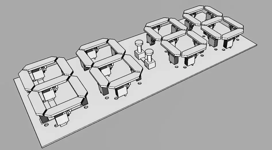
He also printed holders for the electronics. Tony initially used an LM2596 voltage converter to power each of the PWM driver boards but said that they failed after only a few hours of operation. They may have been damaged during setup when the servos are more likely to overtravel and stall, but it’s worth keeping in mind if you’re looking at alternatives to power your clock. He has since replaced these boards with a 5V, 10A transformer which has been working well.
He also added some covers to blackout the servos and hide them a bit better.
His final clock has come out really well:
Any chance of a count up clock?
I have previously made a countdown timer – https://www.the-diy-life.com/mechanical-7-segment-display-driven-by-an-arduino-mega/
It would be quite easy to modify this clock’s code to count up or down using a couple of loops.
Hi Michael, this is a fantastic project, thank you for sharing it. Please can you include a wiring diagram or schematic? I can almost follow your written explanation but struggling to understand where all the leads are to be plugged in. Im looking forward to having a go at this project 🙂
Hi Beth,
Thank you! Sure, I’ve drawn up and included a circuit diagram to help out with the wiring connections.
Good luck with the project!
May i know where can I get the schematic circuit
Hola Michael!! Me encantó este reloj y eh hecho uno pero tengo unos problemas. El primero es que en los minutos no se forma el 2 el segmento 3 no se mueve a la derecha, otro problema que tengo es que vibran los servomotores y por último es que se calientan mucho algunos servos que no se mueven . Gracias
Hi Michael, my name is Uli and I work as a educationer in a primary school. I love that work and will do it with my kids, because we need a “huge” clock outside the school yard. I would like to ask you to do an update, which would help us a lot. Would it be possible to add a thermometer? I have hardly any programming knowledge. But we could use a readable clock/thermometer so the kids don´t always ask for the time and secondly they always want to get rid of their jackets while playing outside. With a readable thermometer they see, for instance it´s 10°C so the jacket has to be kept on. If you could reply on this, that would be great.
Hi Uli,
That could be a nice addition to the clock. I’ll have a look at the possibility of including a temperature display as well, it shouldn’t be too difficult to add.
Hi Michael, my name is Li, From Taiwan University.
At the beginning, I executed it according to your code,
and it passed successfully when verified,
It’s just that will turn red.
The Micro Servos stopped after one action !?
Curious where is the problem?
mentioned is this sentence
<Adafruit_PWMServoDriver.h>
Hi Li,
So is the code reading the correct time and then displaying the time but not updating again? That may be a power supply problem. The servos might be drawing too much power, causing the voltage to dip low and interrupting communication or causing erratic behaviour in the Arduino. I can’t really see any other reason why it would move once and then not again.
How can we test the movement of the servo? We duplicated your diagram but the are not moving
Hi Nino,
The code in the setup function sets up the boards, then remove the for loop and use this line – pwmH.setPWM(i, 0, segmentHOn[I]), replacing segmentHOn with a number from 0 to 500 to move the servo.
If you comment out the code in the loop and the servos still aren’t moving at all, not even initializing, then you’ve either got an I2C communication problem (bad wiring) or the servo’s aren’t getting power.
Hey, Michael.
The compiler is showing this message now,
error: ‘i’ was not declared in this scope
pwmH.setPWM(i, 0, 120[I]),
exit status 1
Compilation error: ‘i’ was not declared in this scope
can you pls help?
can you pls help with the code to move the servos?
Hey Michael,
great Project. Is it maybe possible that you forgot to include the connecting cylinder in the 3d print files?
Cheers,
T
Hi T,
Do you mean the rod connecting the dots to the bases? These were made using sections of 4mm wooden dowels which were then sprayed black. I see I didn’t mention this in the write-up, I’ll get it added.
Thank you.
HIi Micheal. Almost finish my version of the clock. Just some fine tuning to do. Thanks for a great project. Some notes
1. Hardest part was working out the servo settings. I used a small sketch to adjust each one individually and then use the numbers in the final code.
2., A better layout plan for the servos would have been nice.
3. I used four 3D-printed sub-bases for the servos and one for the centre dots, which made locating them easier.
4. I made simple covers for the servos to reduce their visibility a little.
5. I used a great matt black spray paint called ‘Camouflage’ by Rustoleum.
6. The electronics were also mounted on sub-bases on the back.
7. I used a DS3231 clock module, and the code changes were simple. It also has i2c to make set-up easy. Each PCA9685 was powered by its own LM2596 Stepdown converter from the 12 v supply.
I can’t seem to post photos here? Also, is there a simple way to slow down the servos?
Hi Tony,
Yes, setting up the servos properly is definitely the most difficult and time-consuming part of the project.
It sounds like you’ve made some neat additions to the clock, I know quite a few people have asked about different clock modules. It would be great to share them here with some photos as well, you can email them to admin(at)the-diy-life(dot)com and I’ll get them uploaded.
There isn’t really an easy way to slow down servos using the standard servo library. You need to run through loop stepping each increment with a delay between each in order to slow them down. You could write this into a function, but it would probably become quite complex to get the function to simultaneously move an unknown number of servos slowly – rather than moving each servo sequentially to the end stops.
Hi is it possible to get the files for Tony Johnson’s sub bases and also the code changes for the DS3231?
Hi Tony
Could you share the code with the modifications for the 3231 already included?
Thank you
Regards
For Michael Klemens: Love your clock design, and have built my own,but have had a few problems with the coding as I still can’t get a handle on C programming. My 9g servos only have about 100 degrees of travel, and I can’t relate the numbers in the servo travel arrays, which range from 200 to 550. How do these numbers relate to pulse width, as my servos operate within the range of 1 to 2 ms? What is the best way for me to communicate with you as I have some other minor problems that I hope you may have the time and inclination to help me with?
Thank you
Ian Hawke
Thanks Ian.
There is a bit of a learning curve with C, but you’ll get there. Although 100 degrees is a bit less than usual, you should be able to get them to work. You may have a bit more fine tuning to do as you’ve got a narrower band for adjustment. Most hobby servos operate in the 1 to 2ms range so that’s quite normal. The exact pulse timing varies between servo makes and models and even between the same model servos as they typically contain analogue circuits. I’d suggest adjusting the limits (200 to 550) until you hear the servos reach their physical travel limits and then note these limits. You’ll find they’re similar, but not exactly the same for each. You can email me at admin(at)the-diy-life(dot)com
hi
I want to do this project but I was just wondering if I could do this with an Arduino nano instead
Yes you should be able to do this with an Arduino Nano as well. You’re mainly using the I2C interface to control the PWM drivers, which will work on either board.
Hi Michael,
I was wondering what the value is in going with a 12v power supply and then stepping it down to 5v? Any reason not to jest get a higher amperage 5v supply to begin with? Or am I missing something here?
Thanks
Josh
Hi Josh,
There isn’t really any benefit for this project, a 5V power supply with a higher amperage will work as well.
Great project. Best wishes for future projects
Hi Michael,
Could you elaborate on the numbers used to set the travel limits on each servo? I’m assuming the range would be 0 to 360? When starting off, would it make more sense to set all on’s to a certain number and all off’s to a certain number and then attach the servo horns? Like 100 for off and 190 for on (i.e., 90 degree difference)?
Lastly, do you need to power the arduino and the servo drivers separately of using a 5v psu? I used a 5v 3a psu plugged into the arduino’s barrel connector and the power lights on the servo drivers light up, the servos didn’t move. Instead I connected the psu to the servo driver and powered the arduino with a usb power cord and everything worked. Don’t really want to run two PSUs.
Thanks! Love the design.
Hi Kevin,
Yes, what you have stated is correct and is what I had done initially – I think I used 380. You’ll find though that the servos are not all identical and the fairly coarse spline on the servo shaft means that some pieces are not quite perfectly vertical when they’re all set to the same number. So on these servos, I had to adjust the value to get them vertical. It’s a similar scenario with the off limits, though less critical, and some are higher than 380 because they move outwards in the opposite direction to those which are lower than 380. The total range is more like 100 to 700, where 100 or 700 can be off depending on which way they move.
You need to power them separately, but this doesn’t need to be another power supply. The Arduino can’t handle the current draw that the drivers need. You can, however, split your 5V supply and supply the Arduino directly and the drivers directly.
Hope this makes sense.
Hi Michael,
I am almost done my clock. Quick question… Is there an easy way to switch to 12-hour format (i.e., 1:00 instead of 13:00)? Would “#define TIME_24_HOUR false” work?
Hi Kevin,
Someone else asked this question a while back and we had a look at it. I don’t recall that we were able to get the module or library to return a 12 hour time, we settled for putting some code in to just subtract 12 from the hours if greater than 13 and set to 00 if equal to 24.
Hi
Very nice work.
I have one doubt, why is there no need to include the wire.h library if I2C is used?
Thanks and regards
Hi Daniel,
I assume the Adafruit PWM Servo Driver library includes an I2C communication library so that you don’t need to include a second library.
Hi Michael thanks for the great project!
I am building a version of your clock now.
I have added a DS3231 Real Time Clock Module
Clock setting with switches/rotary controller
PIR shutdown when no one is around – clock displays –:–
Safe power up from any setting
Still a work in progress and will post details when work is complete here and my site
These sound like some nice upgrades to the project!
I too have implemented a RTC and buttons to update the times. Also added in temp and humidity sensors, but still working on the integrations for them- idea is that one button launches into a time setting menu, the other buttons will momentarily display temp/humidity.
Also have created small cases for the servos to completely hide them, and modified the display pieces to perfectly fit the small plastic pieces that come with the servos- makes alignment a lot easier.
Finally, have created spacers to align the servos to the metal backplate so that everything is mm precise.
Maybe it is time for a GitHub repository?
Hi Josh,
This sounds great! It would be awesome if you were able to share some photos of the completed project when you’re done.
Yes, it’s probably a good idea to start up a GitHub repository for some of these projects. I’ll have a look at doing so this week.
I’ve created a Github Repository for this project.
Have you finished it yet? Can you please share your code please?
Thanks for the Github link.
Is this clock on Thingverse https://www.thingiverse.com/ ?
It’s a great place to put your 3D printed projects.
From the comments above sounds like there are many different add on parts out there.
Everyone on Thingverse can add their own remixes to your project with all the parts on display and easy to download and they all link back to your clock.
I’ve uploaded all of my files to thingiverse – you can find them here if you search for 4846668 I have designed all in TinkerCad.
A few comments.
I printed the segments in hyperfine mode, with 20 layers solid. this gives a very nice solid color to the face. I then sanded the sides, masked the face, and spray painted all the sides with primer, then flat black. There are two segments – one with a full hole and one with a partial. My printer gave me issues with the partial hole, so I had to use the full one.
The servo base plate has three different designs. I used the “Control Test” to get the measurements dialed in without the segments popping off all the time. Next I used the functional test to really check all the alignments. Finally, the positioning model is for use with the positioning base to mark where the holes should be drilled.
There is also a Servo Holder, which is what I used to hide the actual servos. The servos fit nicely into the servo bases by friction alone.
I’ve added a small display on the side of mine to help adjusting the time and other setting. – Search Amazon for “MakerHawk I2C OLED Display Module I2C SSD1306” – Sorry, but the website prevents me from posting a link
And the display holder is what I used to mount it to the side.
Finally, there is a PCA9685_Case for the 9685 that goes in the back.
Thanks for the files on Thingverse. Can you put your code files on Thingverse as well? Would be great to see your software version of this clock.
I have almost completed testing and build on my version.
I have added FTP sync of time and a 60 LED backlight showing seconds using a Wemos D1 Mini
Once complete I will upload details to Github/Thingverse.
Very incomplete details can be seen here http://www.brettoliver.org.uk/servo_clock/servo_clock.htm
I took another path, using WS2811s. The seven-segment digit is just one chain of LEDs programmed serially using a standard library. The laborious part was just cutting up a reel of WS2811s and then soldering wires between them to get the lengths so it would fit into a 3d-printed casing for the digit. https://www.thingiverse.com/thing:4966469
That looks great Ted. Yeah, I would imagine cutting the sections up would be quite time-consuming!
I made your clock but nothing is moving. Are there any modifications to be made in the code?
I checked the cable it seems right
Hi Yohann,
There are many reasons why nothing is moving, ranging from problems with the hardware or problems with wiring to problems with the power supply and potentially the code. If you’re using the same boards that I have and your connections are the same then it’s quite unlikely that the code is the issue. From my experience, I’d say that if nothing is moving then it is most likely a power supply issue or your connections to the servo control boards are not correct.
hello mickael, I think my problem comes from the arduino board, I use a Mega 2560 R3.
I therefore connected the SDA and SCL directly to the corresponding terminal blocks but still no movement.
Do you think there is any other change to make?
otherwise I can buy a UNO and take the test.
Hi Michael, I like your project very much and it has been a very good example for me for my university graduation project. I will take some of the project inspiration from you and then add my own customizations. I would like to ask you a question so that there will be no problems in the future. I can’t buy the power supply (Turnigy 5A (8-26v) SBEC for Lipo) that you use to feed the PWM motor drivers in the video. Is it okay if I use “LM2596” instead? Do you recommend me to use this component? Can you give me a suggestion on what to do if I use this component? Thanks in advance.
Thanks Berkan, good luck!
You would probably need to use two of them – one for each driver – as 3A is probably not enough to drive all of the servos. If multiple servos move at once you’ll probably have trouble with the power “dipping”.
Hello Michael, very good the project, I already bought most of the things but I am missing 4 things but I made a mistake in one of the parts I bought the 12 v source but 2 ampere I think I was wrong the device with batteries raises the amperes I do not remember how It is called but it is bec of 5 v shared in the video that you recommend me to do, thank you
Hi Diwgo,
I’m not really sure what you are asking, but yes you’ll need to use some sort of 5V BEC or 5V power supply to power the servos and this probably needs to be at least 3A to drive all 4 digits.
Gracias muy bueno
thanks again, bone with only 3 amps the 28 servos move in comment, you have answered that you need two voltage regulators with the LM 2526 and the PCA drivers do not burn when making that connection as they are in bridge mode thanks
Hi I found it is best to replace any servos that are slow to move as they will still be trying to move when other servos are moving . This increases the current draw massively.
On my site http://www.brettoliver.org.uk/servo_clock/servo_clock.htm#code There is a sketch to test each digit in situe in this clock and another for testing individual servos.
Again reject any slow moving or noisy servos . Hope this helps.
Hey Michael
Great Project. I’m currently recreating it for school.
I just wanted to ask if the 5V 5A Battery Elimination Circuit is required or optional. I can’t find any instructions on how to install it, I’m quite new to this so forgive me if I’m missing something obvious.
I built the rest of the clock with the same parts as you, but when I plugged it in and loaded the code nothing happened. All the parts light up but the servos aren’t moving.
Hi Yannick,
Yes, you’ll need the 5V 5A battery elimination circuit to power the servos, the Arduino’s onboard regulator can’t supply enough current to drive that many servos.
I have a 5v4a power supply, it works the same
Hi Micheal! wonderful project. we have done the some project but with PIC877. the clock work but we still have some problems. we used the servo with 180 degres. we have not the some position of the servo. is not like you. we puted the servo in the axe of each segment. could I ask you to help us? We want use arduino for our clock so could you please change the program of the clock using 180 degres of servo movement instead of 90 degres? Many thanks in advance for your help
Hey Michael,
I have a student building the clock. The code loads fine and we have all the parts connected like your diagram but nothing moves. Do you have any suggestions?
Hi Michael!
We are having trouble with the wiring of the servo motors. When first initializing the program should it first display 88:88. Also the correct time is not being displayed. I am unsure of what to do from here.
I made this clock a few years ago, but I have noticed several times that the servos have broken. my thoughts here is that the sevos are constantly on and therefore wear out quickly. Can someone please help me to solve this problem and perhaps know if my theory is correct?
hi
i have a problem when i start the program segment number 3 and 6 on both minute and hour side are stuck on one place and they doesn’t move i thing it’s code problem can you help me
I have modified the code for a GPS clock using ESP32 and a GPS Neo 6M module based on your initial code. I found your code to be perfect and easy to adapt to my new project idea. Thank you very much for providing such helpful and well-written code!
I have modified the code for a GPS clock using ESP32 and a GPS Neo 6M module based on your initial code. I found your code to be perfect and easy to adapt to my new project idea. Thank you very much for providing such helpful and well-written code!
HI! thanks, great project, just a little thing, he asked me to also include the library, after downloading and adding it the program works, even though I haven’t physically tried it yet. does it work anyway?
hi my hour second digit servo motor number 2 is not working properly can you guide me please
hi my hour second digit servo motor number 2 is not working properly can you guide me please
remaing is ok can you tell
https://youtu.be/brtGPaPvMV8
This project is so cool. Thank you so much for posting this!
https://www.youtube.com/watch?v=XQKKu5q2OEo&t=2s
https://seanosullivan.dev/projects/clock/
That’s an amazing project! I’m blown away by the creativity of using 28 servos to build a mechanical 7-segment display clock. It’s like a mini army of servos working together. I can only imagine the precision needed to get all those segments moving in sync. Have you ever had any issues with the servos jittering or not moving smoothly? And how did you manage to fit all those components neatly together? I’m itching to try something like this myself!
That’s an impressive build! Using 28 servos sounds like a lot of work. How did you manage to sync all those servos so precisely? Any tips for others attempting a similar project?