I’ve always been fascinated with mechanical flip displays, like the ones used in airports, and mechanical 7 segment displays like those used in old ball game score boards. I came across a project online in which the builder had started putting together a single digit seven segment display which used solenoids controlled by an Arduino to actuate it. I have seen micro servos used in all sorts of robots and bionic arms, so I thought it would be a nice idea to try and actuate a 7 segment display using servos. The Arduino Uno, which I usually use for Arduino projects, only has 6 PWM outputs, so I had to get the Arduino Mega. The Mega has 15 PWM outputs, so it was perfect to duplicate some parts of the code and make a two digit display which could count down from 99 (or up to 99).
Here is a full guide with the Arduino code and the 3D print files to build your own mechanical 7 segment display using an Arduino Mega and 14 micro servos.
This guide assumes that you’ve worked with an Arduino micro-controller before and know the basics of programming an Arduino. If you do not, follow the linked guide for more information on creating and uploading your first sketch.
Here is a summary of the build and a video of the display in action. Continue reading for full step by step instructions along with the code and print files.
What You’ll Need To Build A Mechanical 7 Segment Display
- Arduino Mega – Buy Here
- 14 X Micro Servos – Buy Here
- 5V 5A Battery Elimination Circuit – Buy Here
- 12V Power Supply – Buy Here
- 3 Pin Header Strip – Buy Here
- Strip Board – Buy Here
- 3D Printer & Bright Filament – This One Used
How To Build The Display
Assemble The Display Components
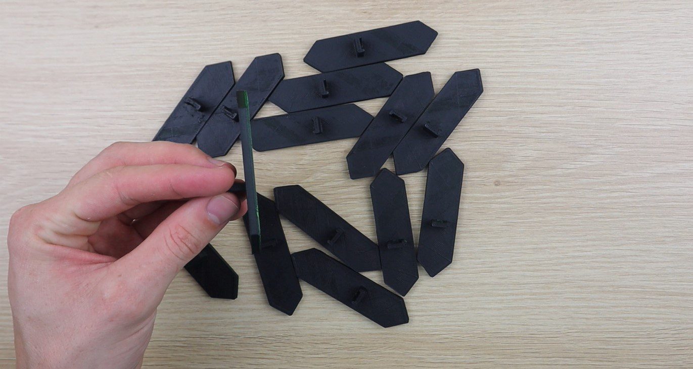
To start off, you’ll need to print the segments and mount them onto the servos. The segment is identical on all servos, so you’ll need to print out 14 of them.
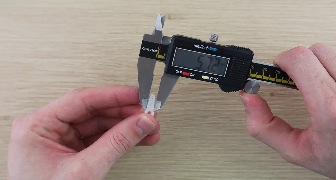
I measured up the servo arms to design a segment which could be glued directly onto these arms without requiring any other hardware.
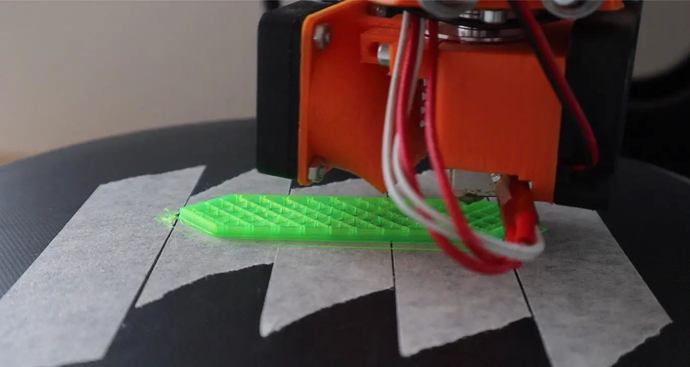
I then 3D printed the 14 segments using translucent green PLA at 185C with an infill of 15%. This did lead to the fill pattern being visible through the segments in operation. I don’t mind this look but if you want them to look more solid then either use a solid coloured PLA or print them with 100% infill.
You can download the 3D print file here – 7 Segment Display Piece
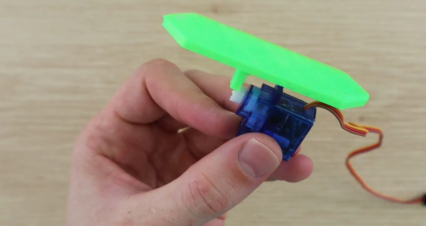
I started off by printing a single segment to check that it fitted the servo and to have a look at how it operated (that it was light enough) once glued to the servo. The segment was glued onto the servo arm using hot melt glue, epoxy will also work.
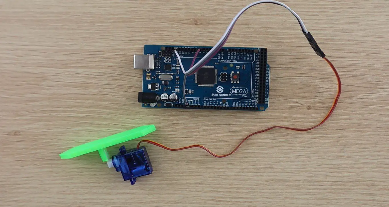
Try to align the segments so that they stand flat when the servo is square on its base. I connected the single segment and servo to the Arduino to check it’s operation.
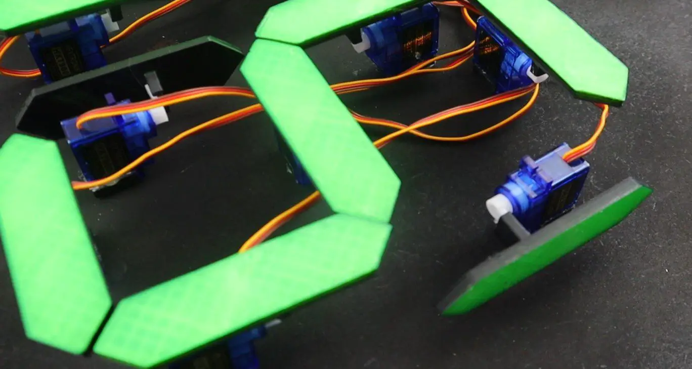
During this test, I saw that the edges of the segments would be quite visible even when they’re turned through 90 degrees, so I’d need to colour of the side of the segment to blend in with the back board. I decided to spray the back and sides of all of the segments in black to match the back board.

There is now a significant difference between the top face and the sides of each segment.
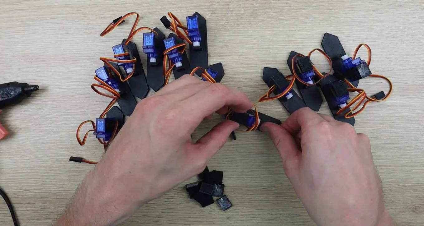
Once I was happy with the segments, I glued them all onto the servos and added a small spacer block to each servo so that they are able to stand upright.
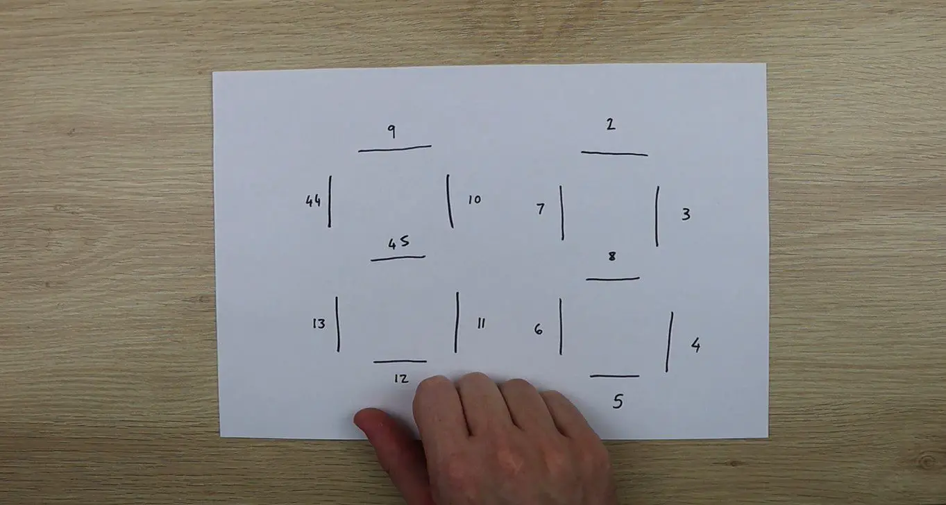
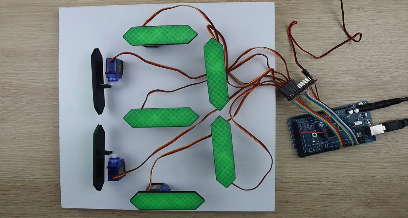
I then mapped out which segments would be connected to which pins on the Arduino Mega so that I could build the wiring harness.
There are 12 PWM inputs sequentially from 2 to 13 and I then had to use pins 44 and 45 as additional PWM pins for the last two segments.
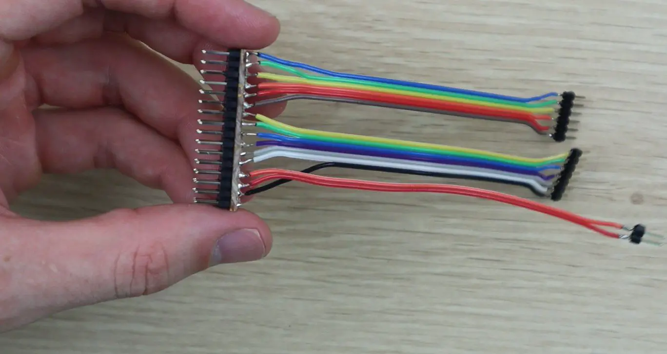
The Arduino Mega cannot supply enough power to all fourteen servos, so I used a battery elimination circuit module made for RC aircraft to supply power to them and the Arduino to drive the IO pins. There is a closed look at the strip board and pins in the video but essentially the strip board supplies the GND and 5V pins from the BEC and then connects the GND and all of the PWM pins to the Arduino.
After I built the wiring harness, I decided to test build a single digit in order to test the code. I laid the servos out in the configuration in which they would be used and then got the code working.
During this step I had to add a few lines to the code to move the segments adjacent to the middle segment out of the way when it way moving up or down so that they wouldn’t bump into them.
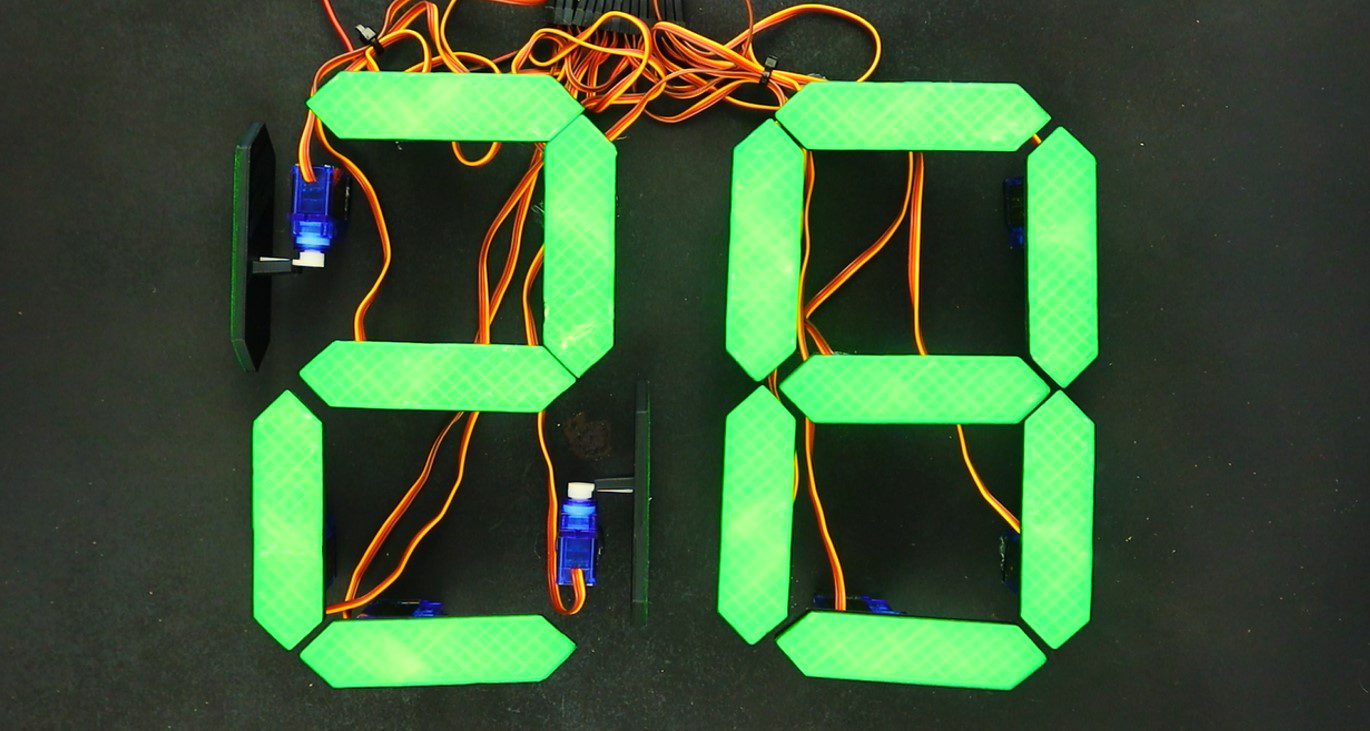
Once I was happy with this digit, I duplicated the code for two digits and then mounted the servos onto a black back board.
Upload The Sketch
This is the final version of the code, the code makes use of the servo library and relies heavily on arrays to store the calibration values and movements of the servos. There is a link to download the code provided after the code.
//Michael Klements
//The DIY Life
//8 February 2020

#include <Servo.h>

Servo myservo[14];

int segmentOn[14] = {90,88,81,80,90,78,98,90,88,65,75,90,78,98};      //Servo on position values for each servo
int segmentOff[14] = {0,0,180,180,0,180,0,0,0,155,180,0,180,0};       //Servo off position values for each servo
int digits[10][7] = {{1,1,1,1,1,1,0},{0,1,1,0,0,0,0},{1,1,0,1,1,0,1},{1,1,1,1,0,0,1},{0,1,1,0,0,1,1},{1,0,1,1,0,1,1},{1,0,1,1,1,1,1},{1,1,1,0,0,1,0},{1,1,1,1,1,1,1},{1,1,1,1,0,1,1}}; //Position values for each digit

void setup()
{
  myservo[0].attach(2);   //Assign all of the output pins
  myservo[1].attach(3);
  myservo[2].attach(4);
  myservo[3].attach(5);
  myservo[4].attach(6);
  myservo[5].attach(7);
  myservo[6].attach(8);
  myservo[7].attach(9);
  myservo[8].attach(10);
  myservo[9].attach(11);
  myservo[10].attach(12);
  myservo[11].attach(13);
  myservo[12].attach(44);
  myservo[13].attach(45);
  for(int i=0 ; i<=13 ; i++)    //Set all of the servos to on or up (88 displayed)
  {
    myservo[i].write(segmentOn[i]);
  }
  delay(5000);
}

void loop()
{
  for (int g=9 ; g>=0 ; g--)    //Large loop counter to count the tens
  {
    int mustDelay1 = 0;
    if(digits[g][6]!=digits[g+1][6])  //Logic to move segments next to middle segment out of the way
    {
      if(digits[g+1][1]==1)
      {
        myservo[8].write(segmentOn[8]-30);
        mustDelay1 = 1;
      }
      if(digits[g+1][5]==1)
      {
        myservo[12].write(segmentOn[12]+30);
        mustDelay1 = 1;
      }
    }
    if(g==9)
    {
      myservo[8].write(segmentOn[8]-30);
      myservo[12].write(segmentOn[12]+30);
    }
    if(mustDelay1==1)
      delay(200);
    for (int h=6 ; h>=0 ; h--)    //Small loop counter to move individual segments  to make up the tens digit
    {
      if(digits[g][h]==1)
        myservo[h+7].write(segmentOn[h+7]);
      else
        myservo[h+7].write(segmentOff[h+7]);
      if(h==6)
        delay(200);
    }
    for (int i=9 ; i>=0 ; i--)   //Large loop counter to count the units
    {
      int mustDelay2 = 0;
      if(digits[i][6]!=digits[i+1][6])  //Logic to move segments next to middle segment out of the way
      {
        if(digits[i+1][1]==1)
        {
          myservo[1].write(segmentOn[1]-30);
          mustDelay2 = 1;
        }
        if(digits[i+1][5]==1)
        {
          myservo[5].write(segmentOn[5]+30);
          mustDelay2 = 1;
        }
      }
      if(i==9)
      {
        myservo[1].write(segmentOn[1]-30);
        myservo[5].write(segmentOn[5]+30);
      }
      if(mustDelay2==1)
        delay(200);
      for (int j=6 ; j>=0 ; j--)  //Small loop counter to move individual segments  to make up the unit digit
      {
        if(digits[i][j]==1)
          myservo[j].write(segmentOn[j]);
        else
          myservo[j].write(segmentOff[j]);
        if(j==6)
          delay(200);
      }
      if(mustDelay2==1)   //Delay logic to reduce delay if the side segments moved (adding an additional 200ms delay)
        delay(600);
      else
        delay(800);     //Delay between digits. 200ms delay already experienced in the code
    }
  }
  delay (2000);   //Delay after countdown to 0 before resetting
}
Download the code – 7SegmentDisplay
This is a high level breakdown of what happens in the code:
I initialise an array of 14 servo objects called myServo, these numbers correspond to the numerical sequence in the pin number diagram.
I then initialise three arrays of numbers. The first, called segment On, stores the on or up positions for each of the 14 servos as a sort of calibration to ensure that they are all perfectly vertical. The second, called segment Off, is the same but for the 90 degree off position. Some of these are 0 and some 180 depending on which direction the servo needs to move. The last is a 2D digit array which stores the segment positions for each digit from 0 to 9, where 1 is on or visible and 0 is 90 degrees or invisible.
In the setup code, the 14 servos are assigned to the correct pins and then a loop sets them all to on, the number 88 will be displayed. The code then waits 5 seconds before starting the countdown.
The countdown is done with four loops. An outer loop controlling the tens and an inner loop controlling the units. In each of these loops, a smaller loop cycles through the seven segments and sets them to the correct position, on or off, by looking up the value in the digit array.
The other logic in this section is purely to move the two segments adjacent to the middle segment out of the way by 30 degrees when this segment moves so that it doesn’t bump into it. This includes all of the mustDelay variables, the 200ms delays and the if statements which aren’t in the smaller loops.
Running The Mechanical 7 Segment Display
Upload your code to your Arduino and your display will be ready to run. It will automatically reset to 88, wait 5 seconds and then start to count down from 99 to 00. When it reaches 00 it will wait 2 seconds and then reset and start counting again.
You can change the number it counts down from by setting the counter in the outer loop g. You will always need to counter from the number 9 in the units digit (i) else each pass it will miss the digits higher than the number it is set to with the code in the way it is currently written. You can’t, for example, set 47 as the starting point, it will need to be 49. If you change it to 47 then it will go down 41, 40, 37, 36 etc.
Here are some pictures of the display in operation. The video has some good footage of the display in operation.
Have you tried to build your own mechanical 7 segment display? What did you use to actuate and control it and how did it work? Let us know in the comments section below.
I am working on the project. just 3D printing out the parts but as I only need to count to max 19 I do not need a full second digit.
I will amend the code as soon as I have it all built !!
Thanks for a great project/
That’s great, enjoy building yours!
Michael, I was hoping I could put some pluses where there were minuses to create an up counter , but I’m a bit lost in your loops. Some direction would be very helpful.
Hopefully Andy
Is there a way to find tune after zeroing the servo to get the silver horn/segment exactly straight you’d have a fine tune control on a for instance RC car what can you do here in this project? Thank you. I’m almost done and ready to go. I’d appreciate any help you can give me.