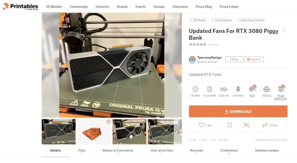
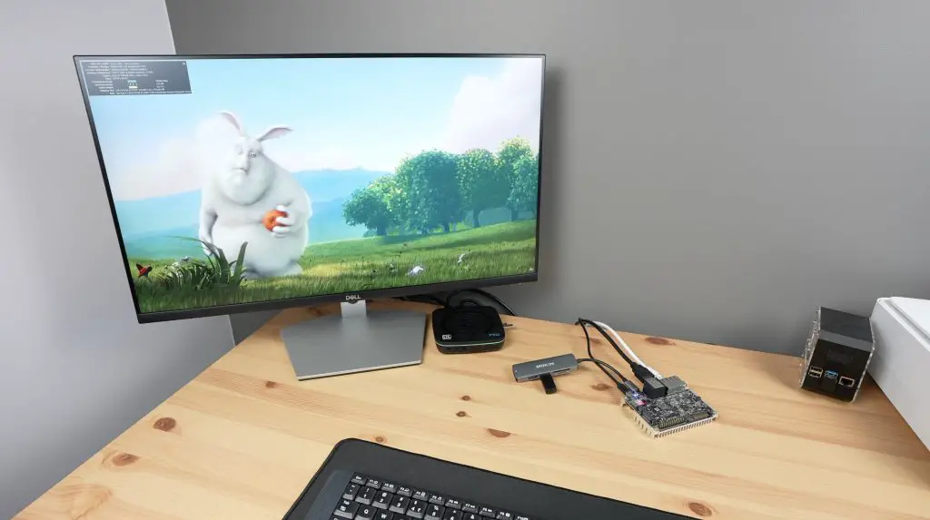
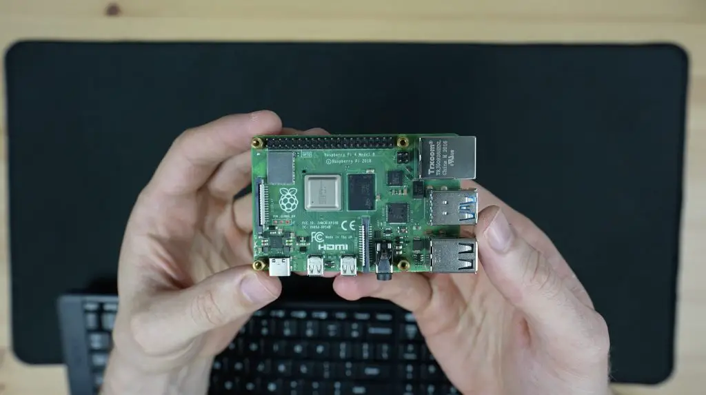
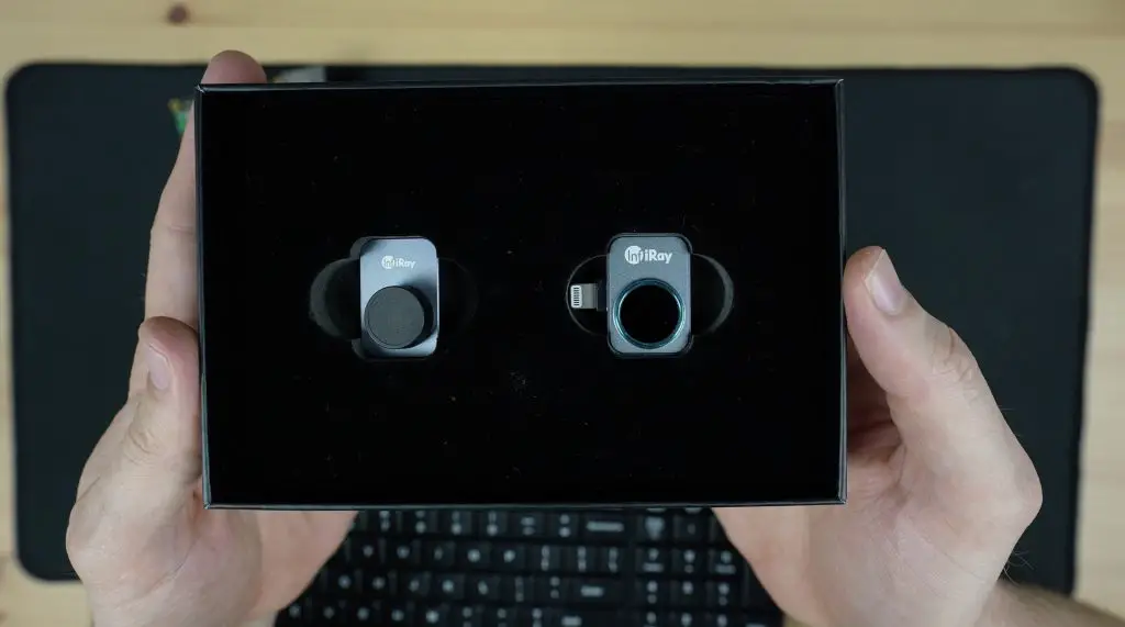
I think we can all agree that the size of modern graphics cards has gotten a little bit out of control. It’s not uncommon for the graphics card to be the deciding factor in how big your computer case needs to be. So that got me thinking, what if instead of putting a graphics card into a computer, I rather put a computer into a graphics card? Well at least into a graphics card enclosure.
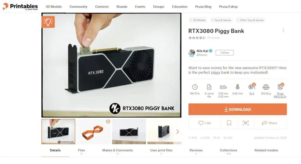
I kind of forgot about this idea for a few months and then the other day while I was browsing Printables, I found this cool money box that is designed to look like an RTX 3080.
It’s obviously partially hollow, so that’s perfect to put a small single-board computer into. So I’m going to be using this model as a basis to build an RTX3080 all-in-one computer.
Here’s my video of the build, read on for the written project;
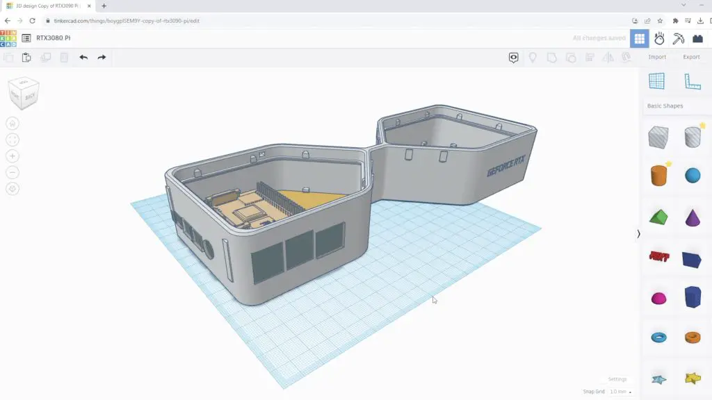
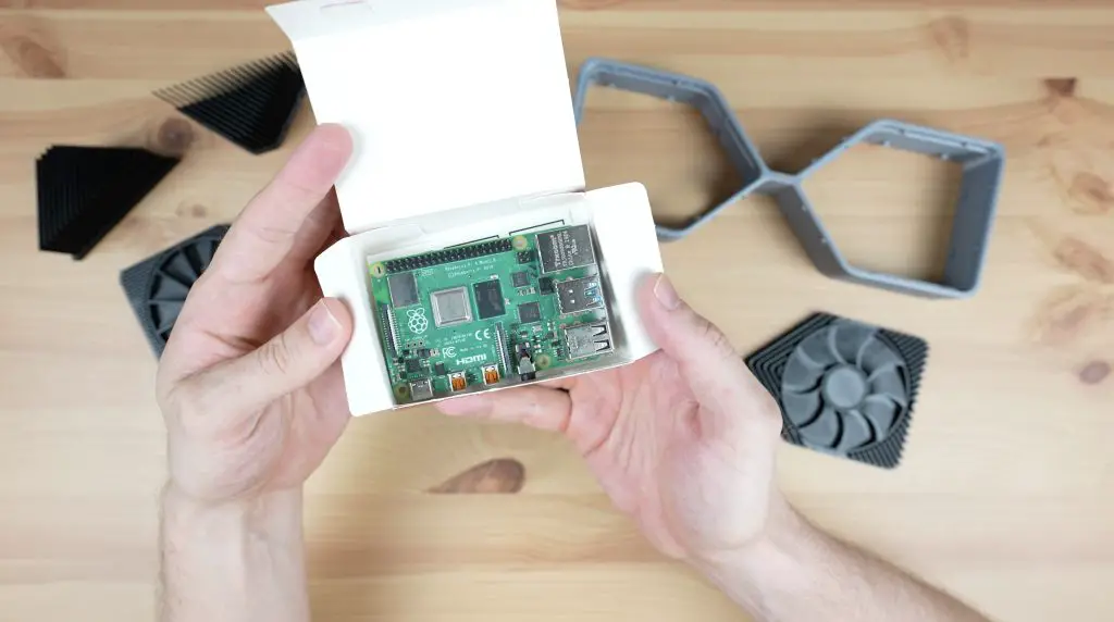
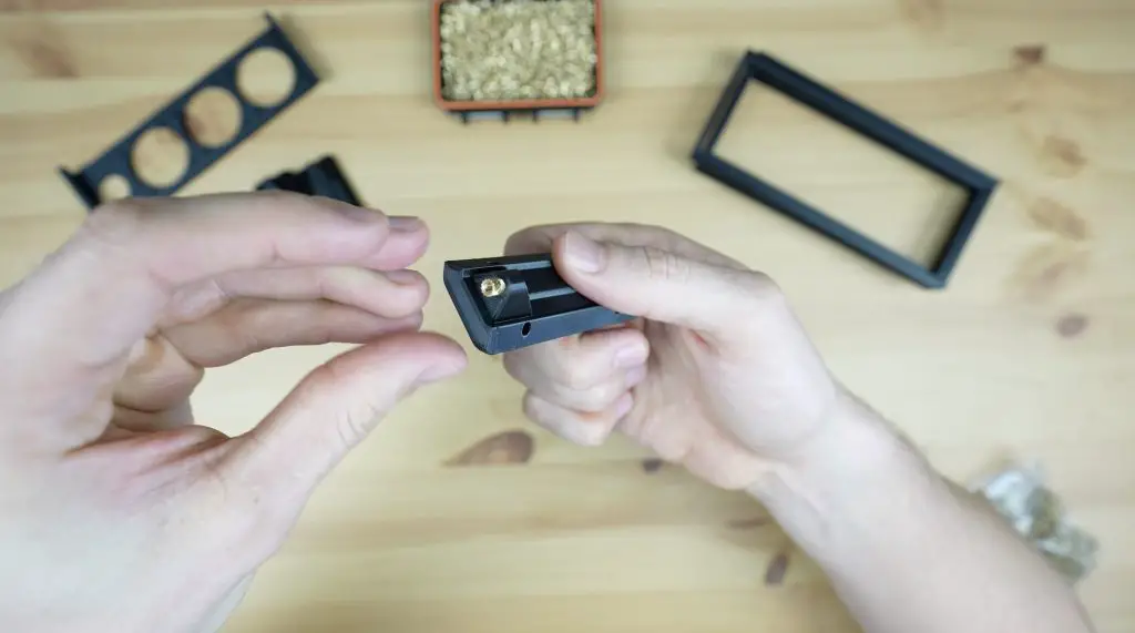
I downloaded the model files and then imported them into TinkerCAD to make the modifications required to fit a Raspberry Pi into it.
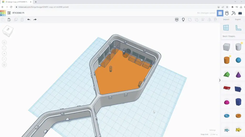
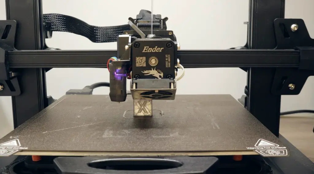
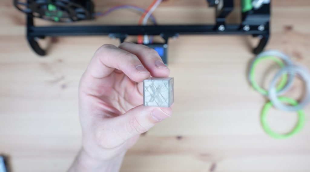
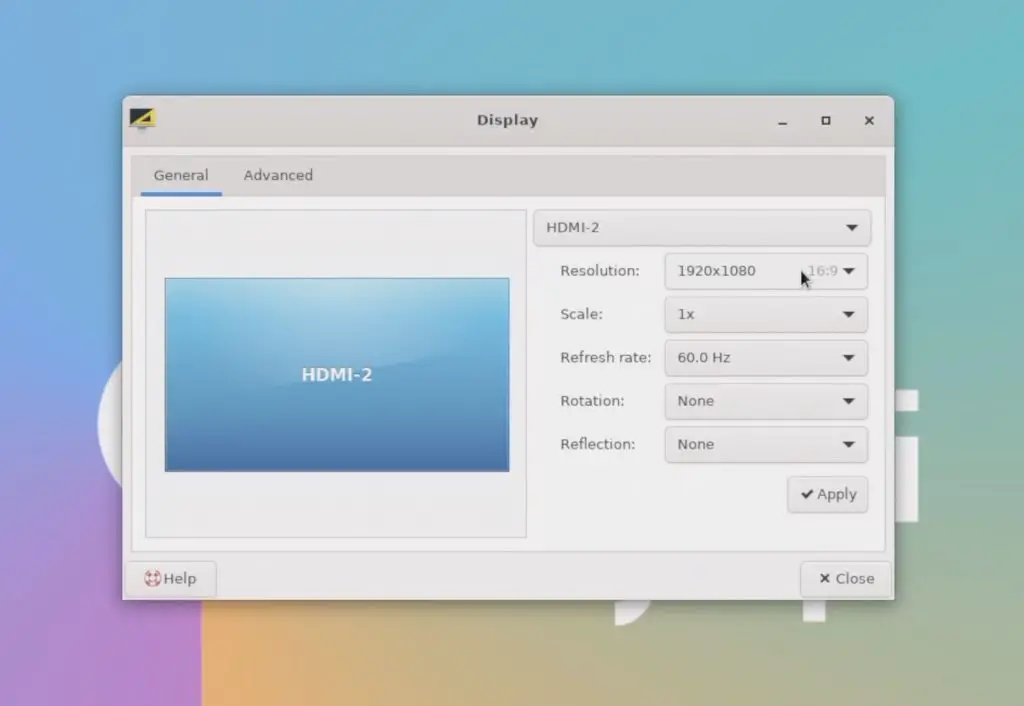
The money box model is scaled down from a full-size RTX3080, so you need to scale it up to 142% to be size for size. This exceeds my print bed size by a few millimetres, so I scaled it up to 130%.
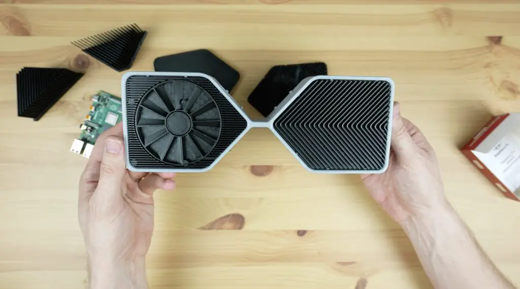
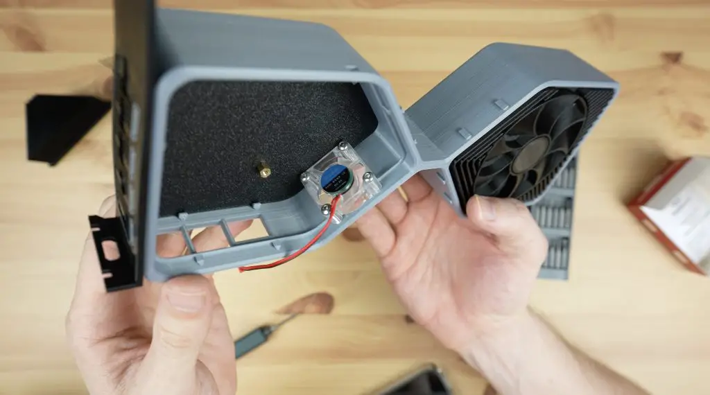
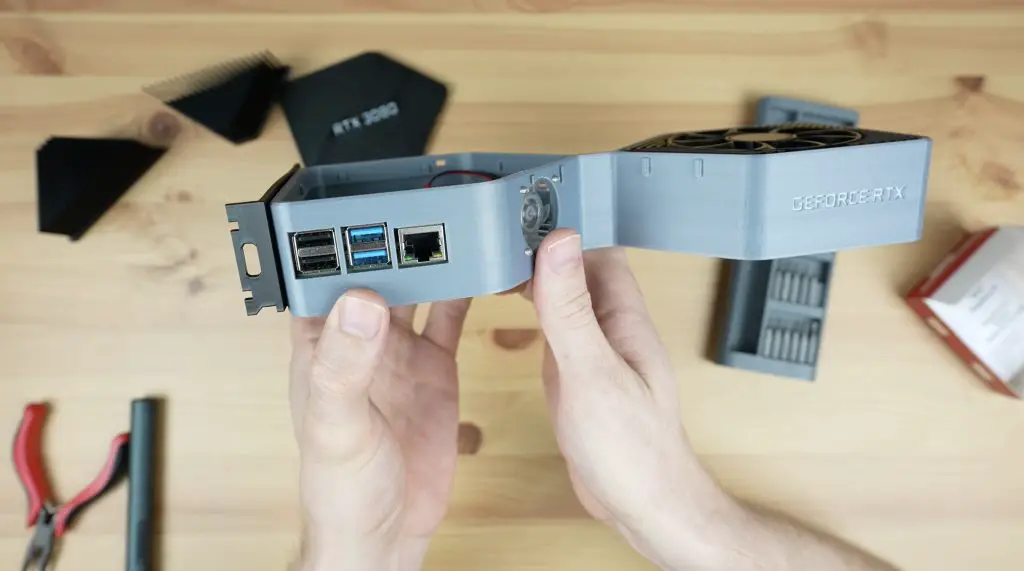
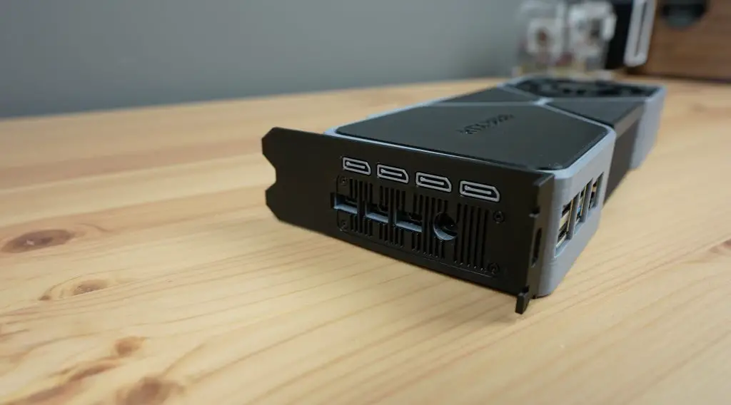
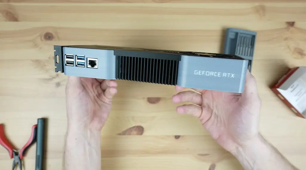
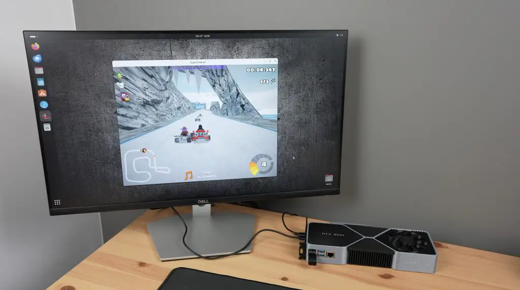
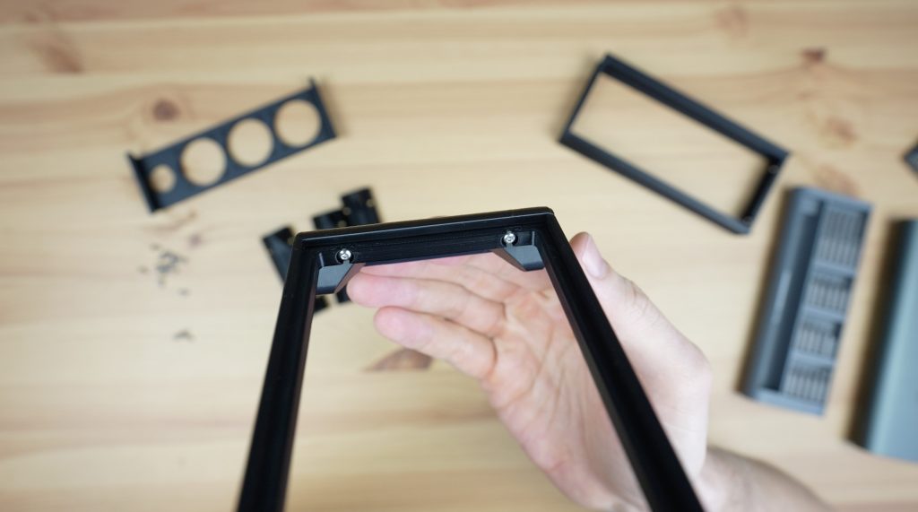
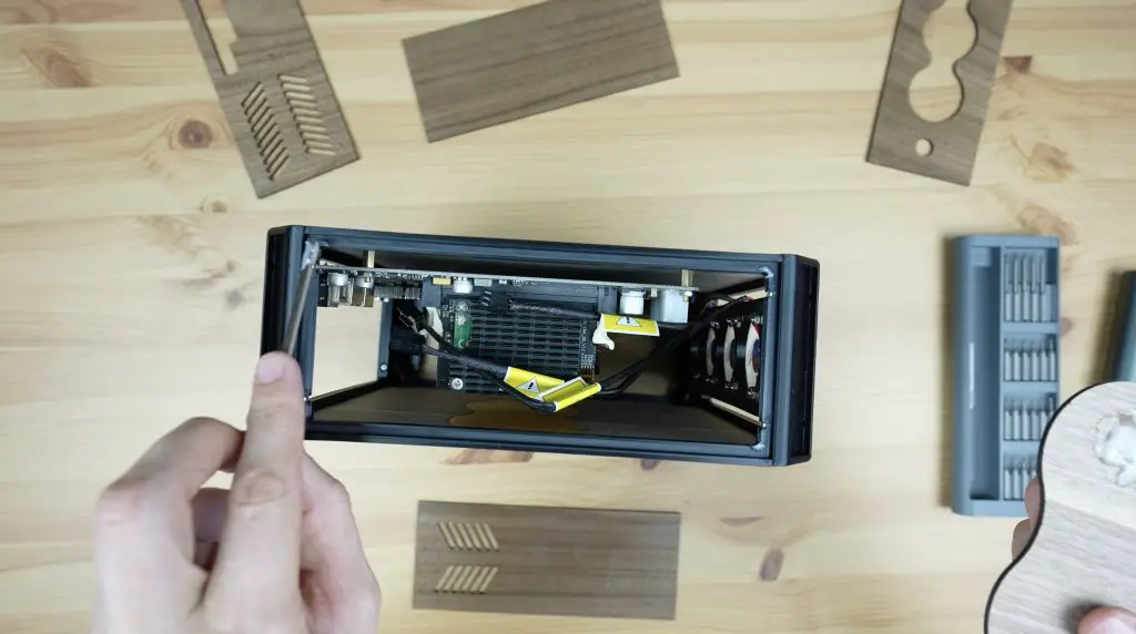
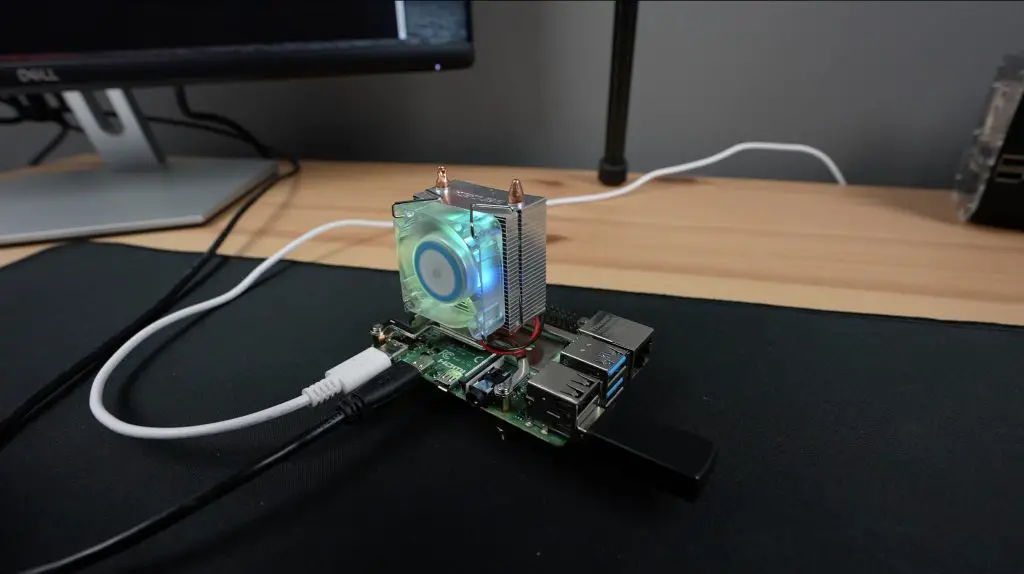
I oriented the Raspberry Pi in the back end of the RTX3080 so that the HDMI ports are in the same general area as the original display ports. We also have a power input here, which, unlike the RTX3080, can run on a USB-C power adaptor rather than requiring a small power station.
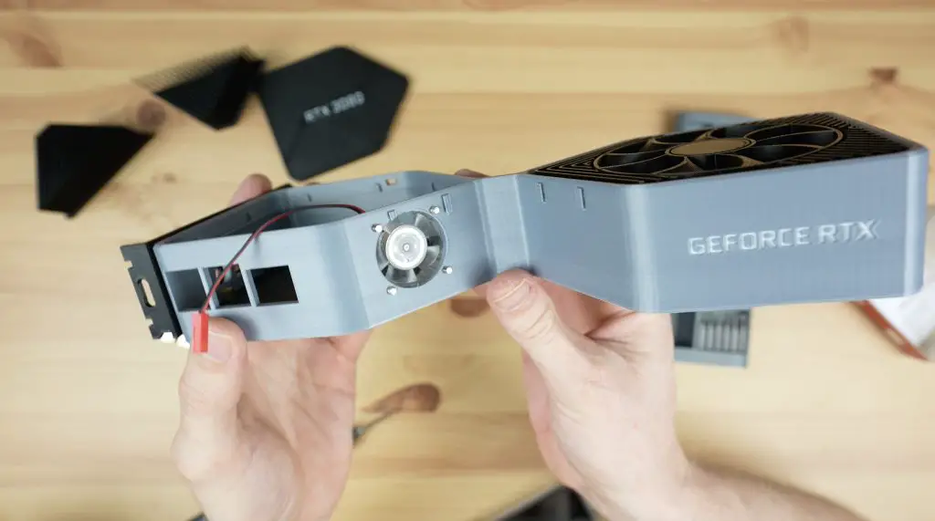
The USB and Ethernet ports then extend out the side of the GPU, which I think looks pretty cool.
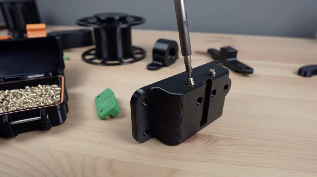
I then added supports and holes to accommodate some brass inserts in the base to mount the Raspberry Pi.
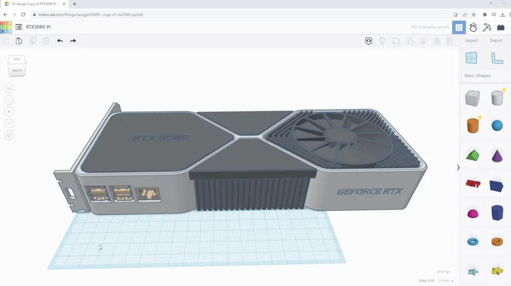
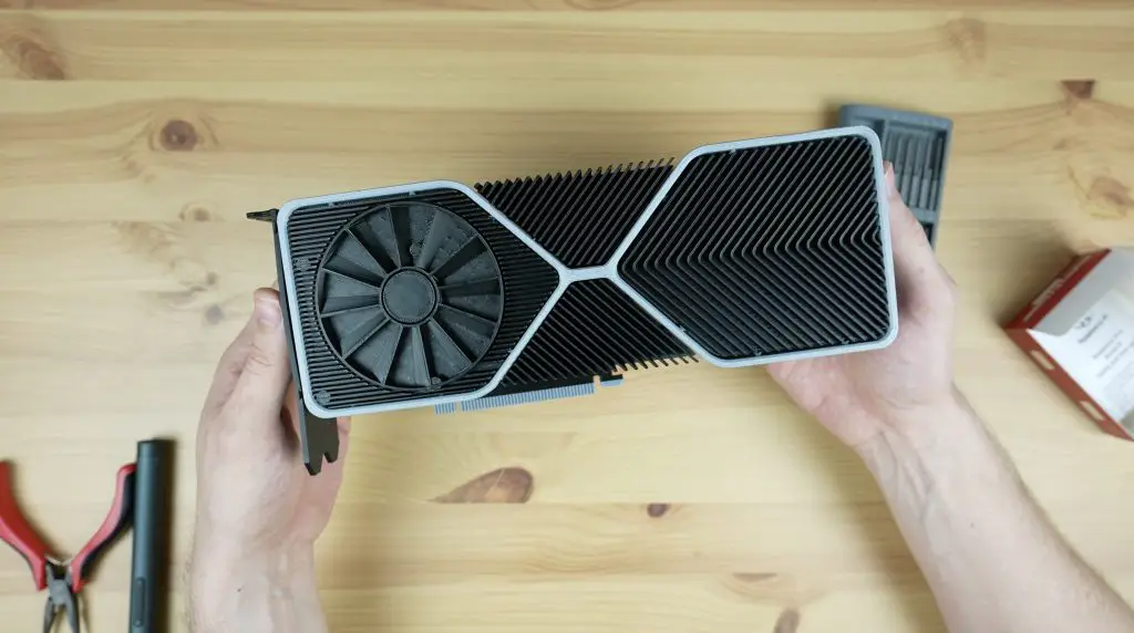
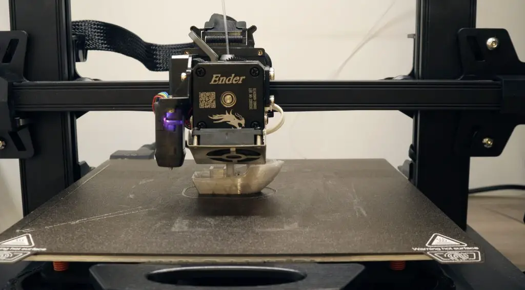
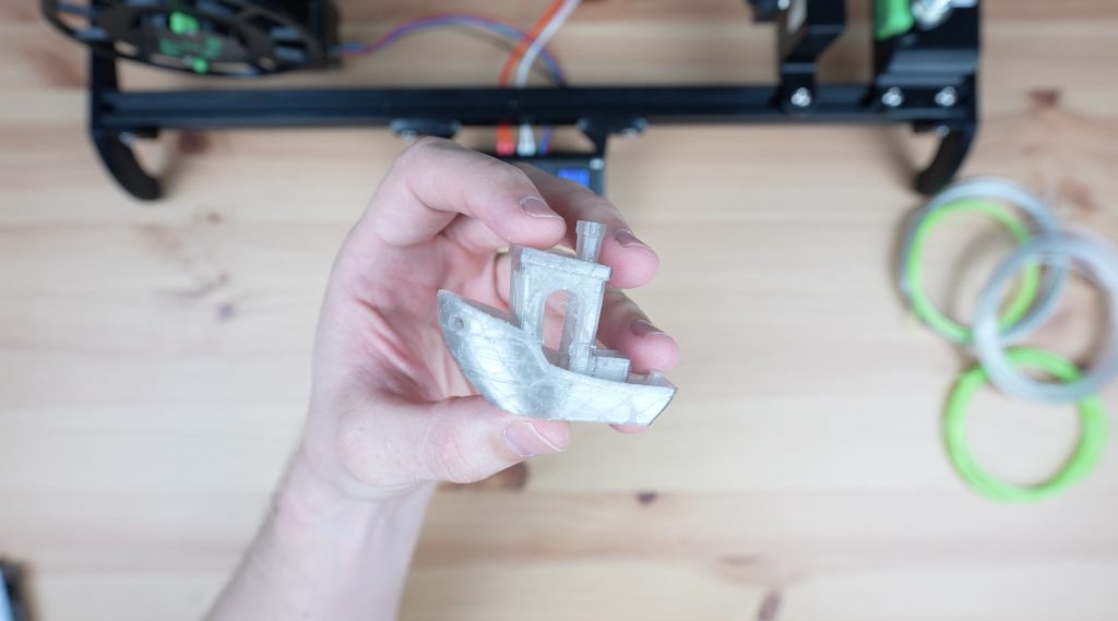
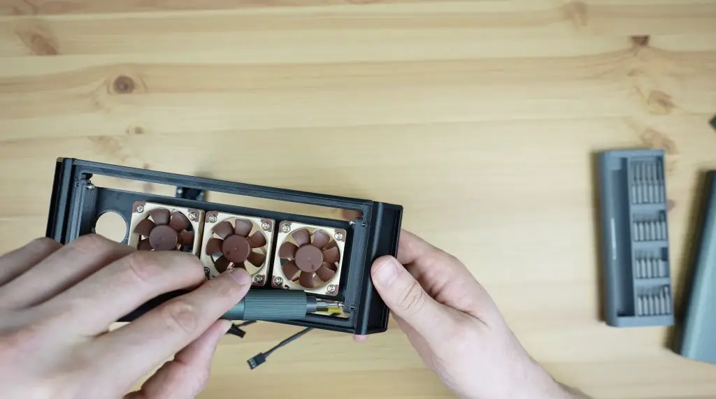
And lastly, we need to think about cooling. I initially wanted to use an actual fan in place of the 3D-printed fan covers but the fan on the Pi’s side of the card is underneath the Pi, which means that the GPU would need to be lifted off the desk to get airflow to it. It also gets in the way of mounting the Pi. So I decided to instead mount a more appropriately sized 30mm fan onto the inside of the housing and have it draw air in through the fin stack on the side. This required a fan cutout to be added to the side and a few cutaways to the surrounding heatsink parts to make some space for it.
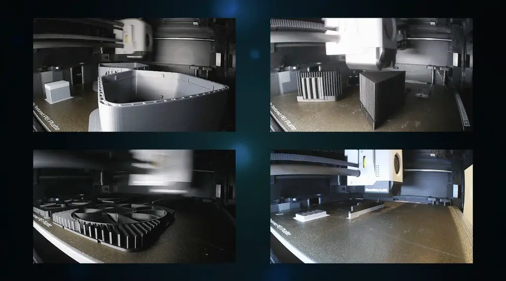
With that done, we’ve got the 3D model complete and ready for printing.
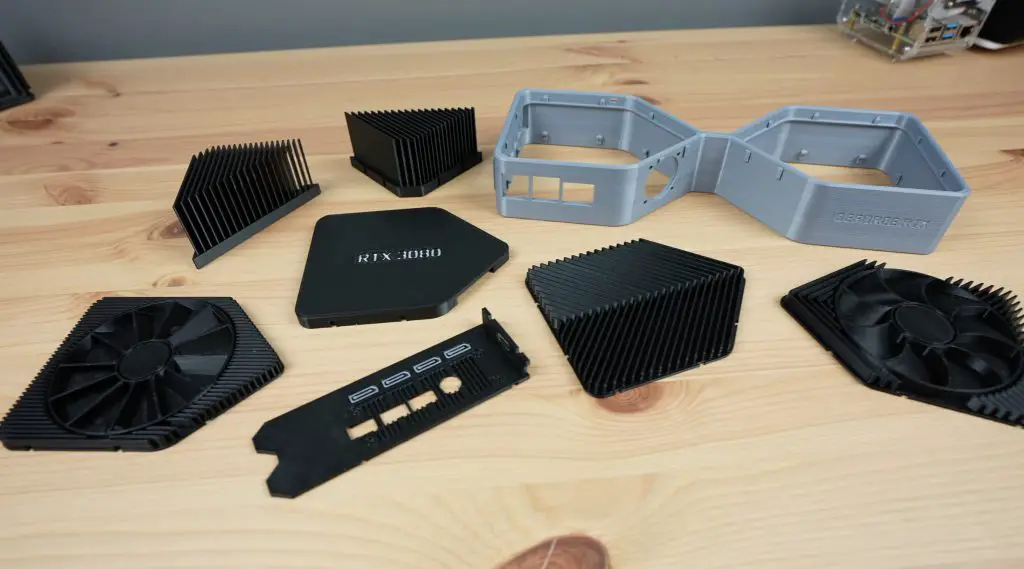
I also noticed that another user had made fans for the RTX3080 money box model that were a bit more accurate to the original design. So I went with this fan design for the top fan. The bottom one I left as the original as it was better suited to holding the supports that were needed for the brass inserts to mount the Pi onto.
3D Printing The RTX3080 Parts
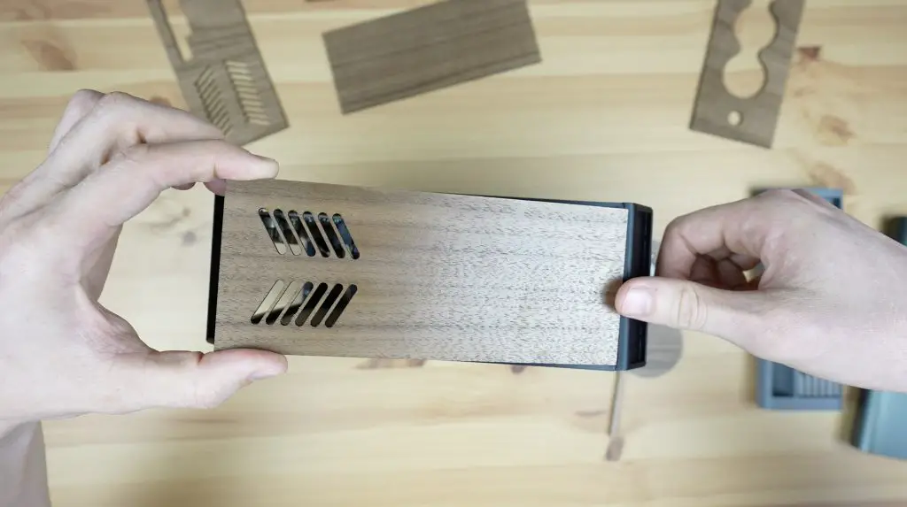
I printed out the components using grey for the main body and black for the heatsinks, fans and backplate. I coloured the text in white so that it stands out better and looks a bit more like the original card too.
I use PLA for most of my 3D printing, as I’ve used here, and I think the parts have come our really well – particularly the heatsinks!
Assembling The RTX3080 Pi Case
Now we can move on to installing the Pi into the enclosure.
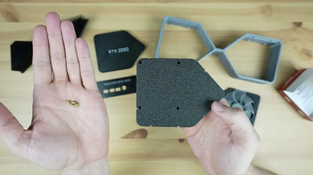
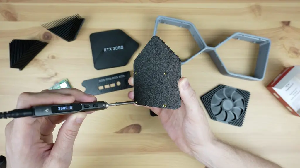
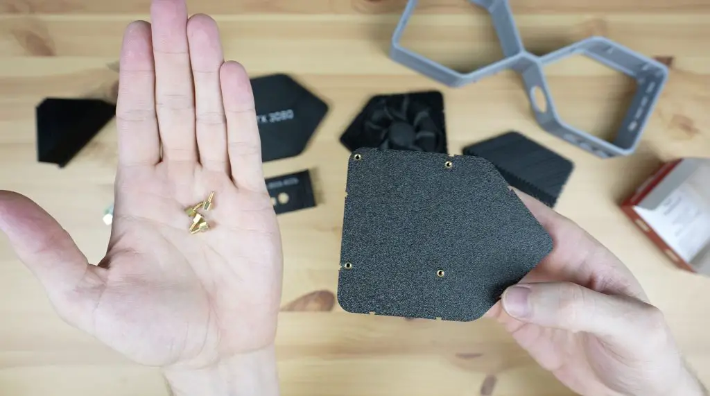
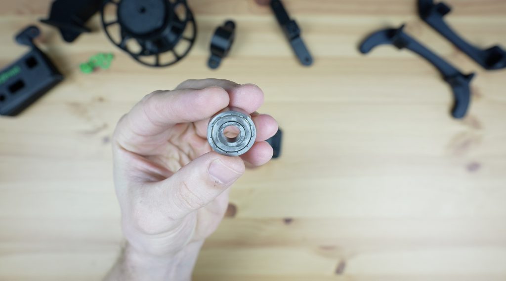
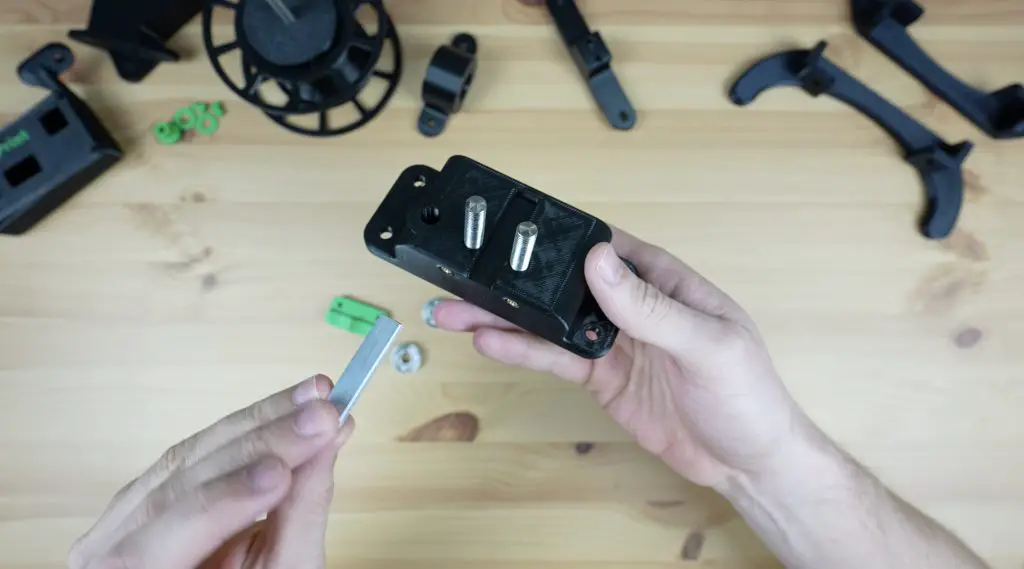
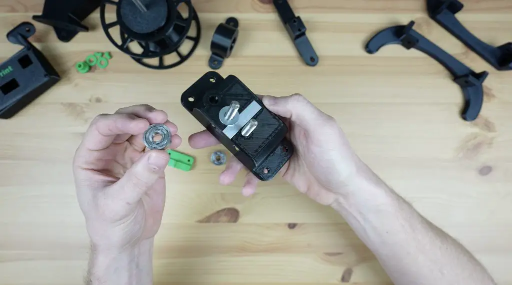
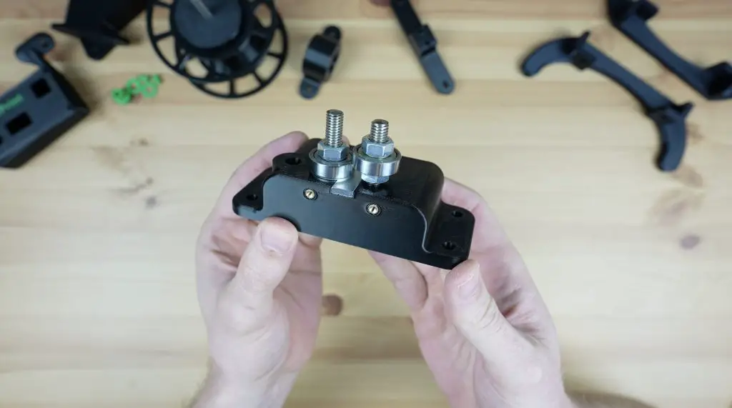
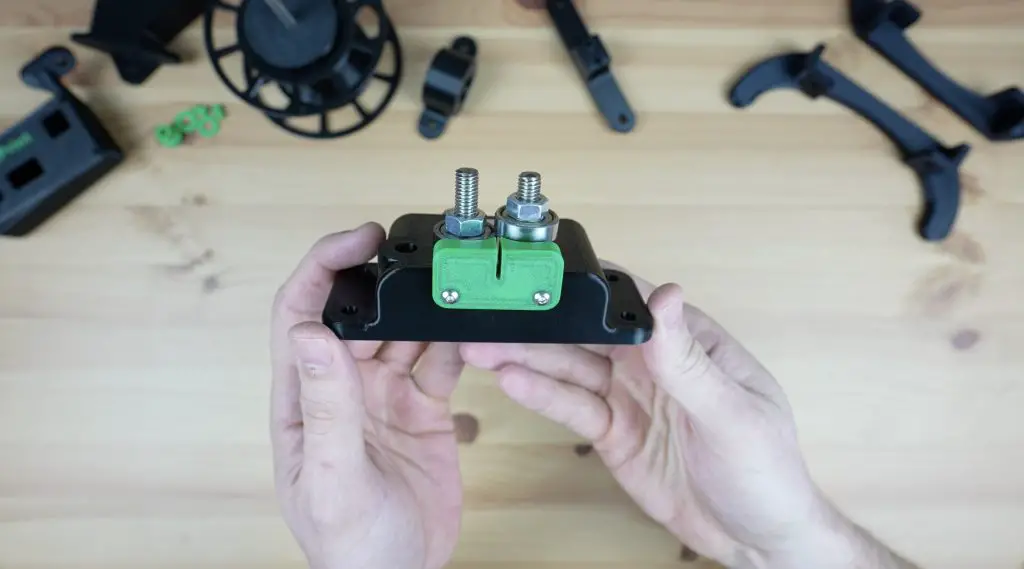
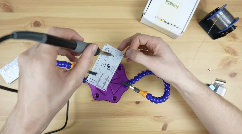
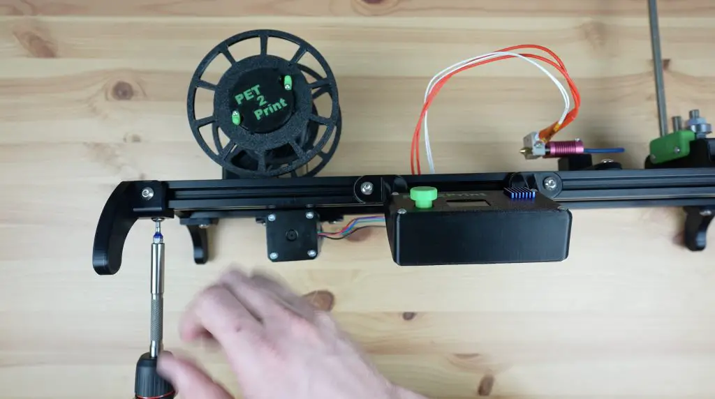
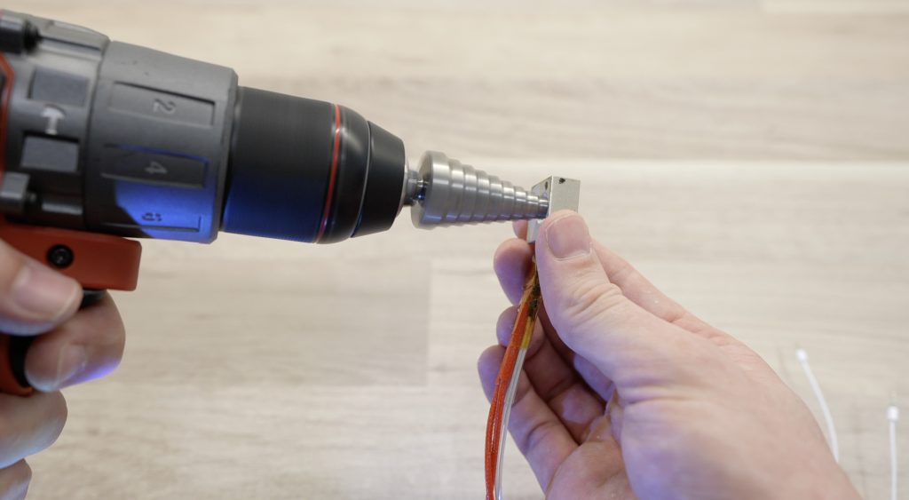
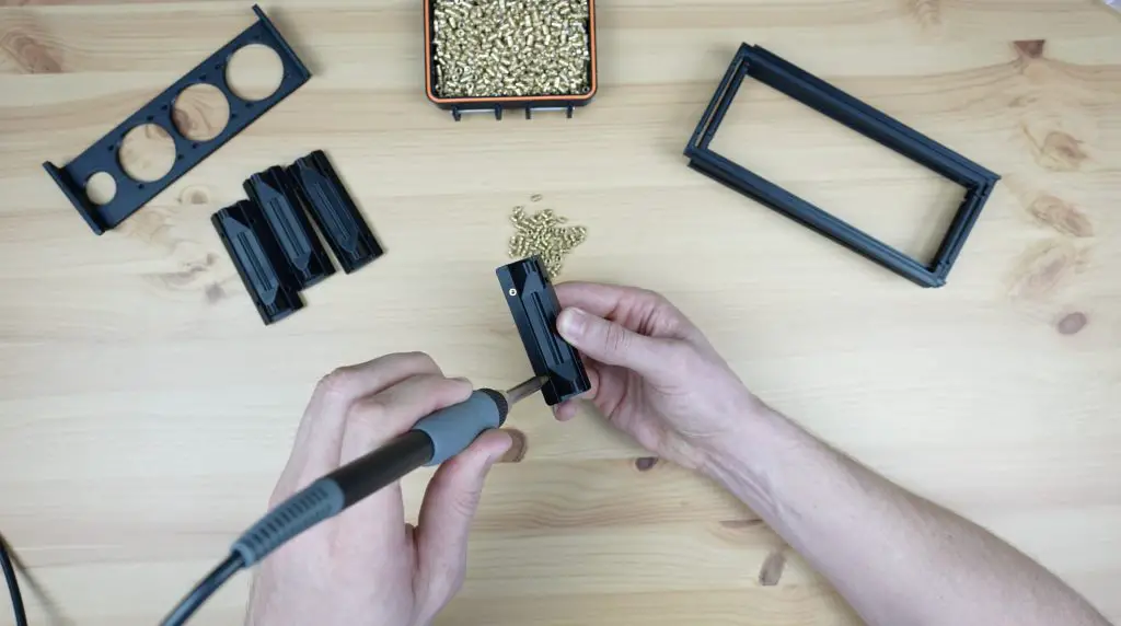
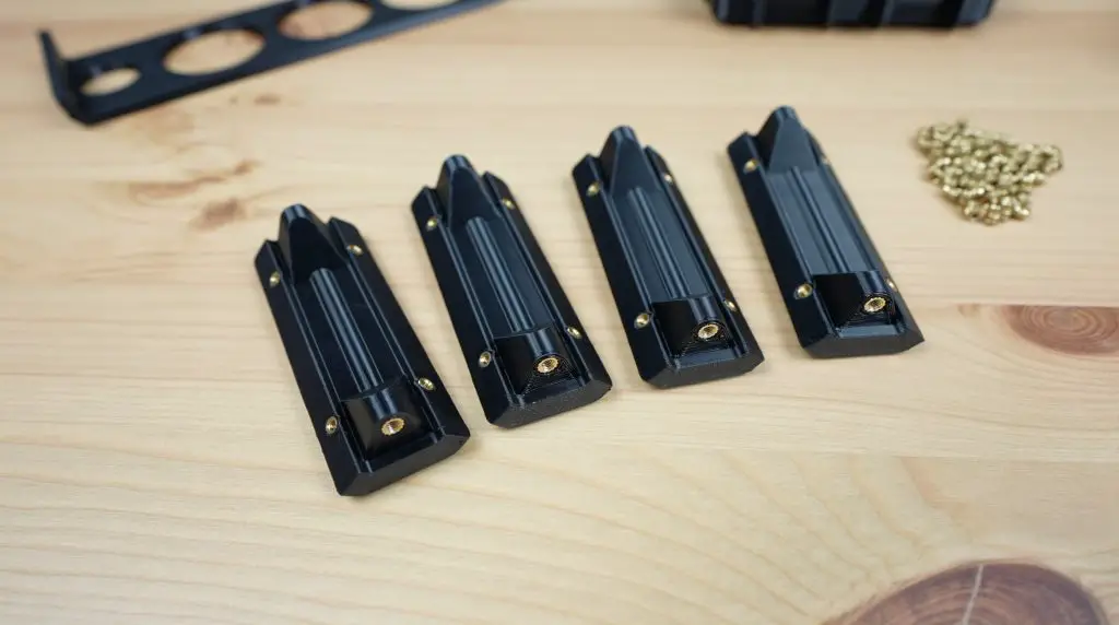
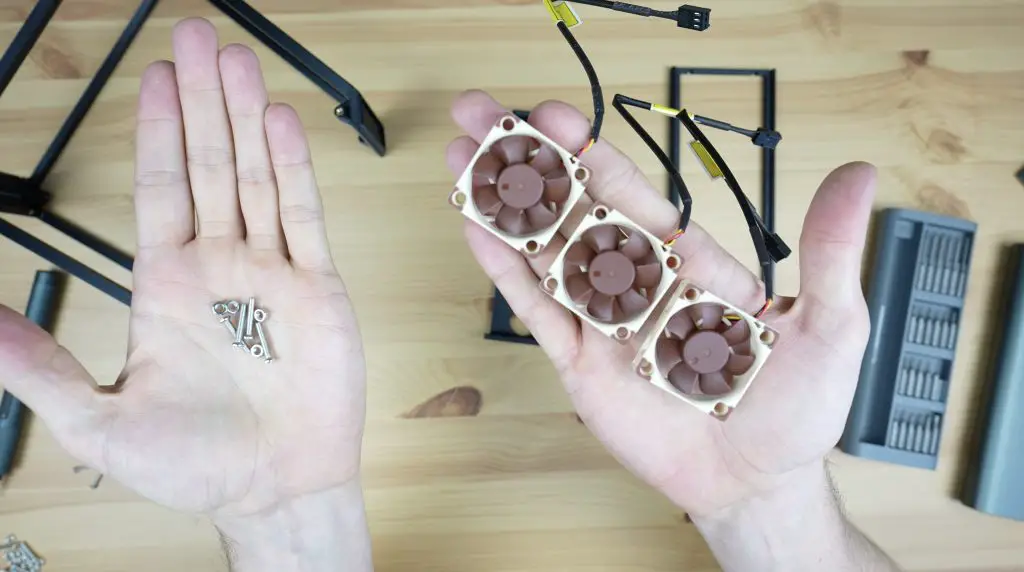
First, we need to add some M2.5 brass inserts into the bottom fan piece. We just melt these into place using a soldering iron.
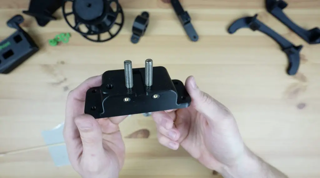
Next, we can add some M2.5 x 4mm brass standoffs to mount the Pi onto. I didn’t have 4mm ones so I’ve cut the top off some 6mm ones with a Dremel to shorten them.
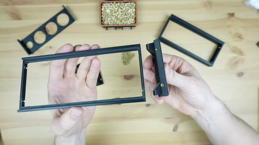
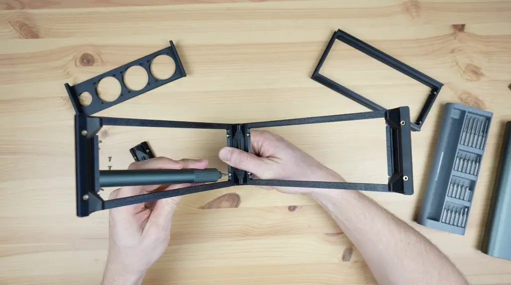
I’m not going to mount the Pi onto the standoffs until we have partially assembled the card, so let’s snap the components into place first.
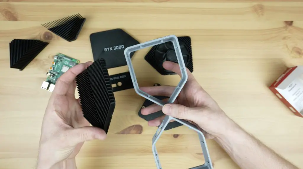
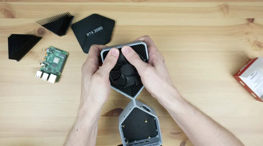
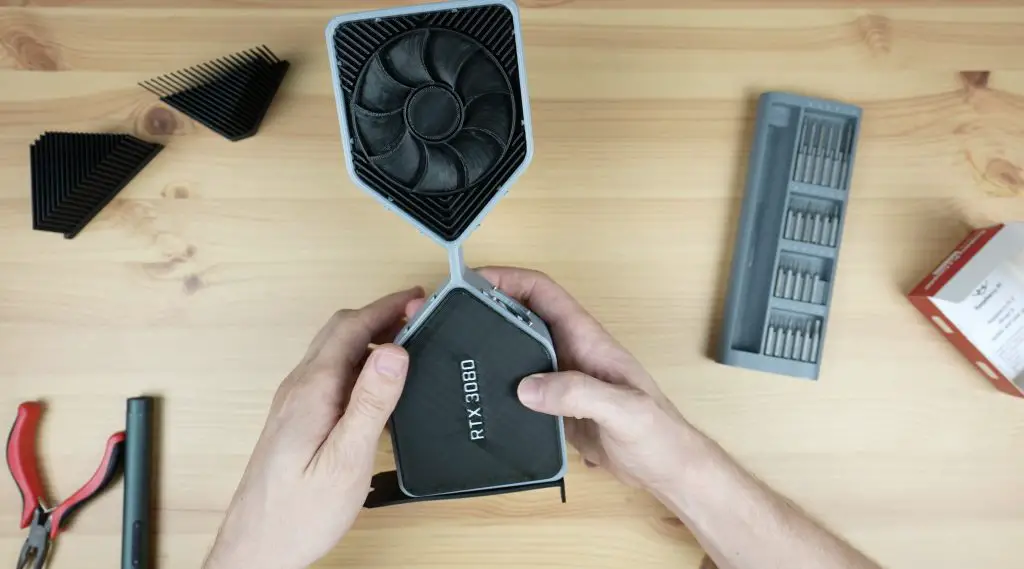
We can push the bottom fan and heatsink pieces into place.
Then add the back plate and the top fan plate.
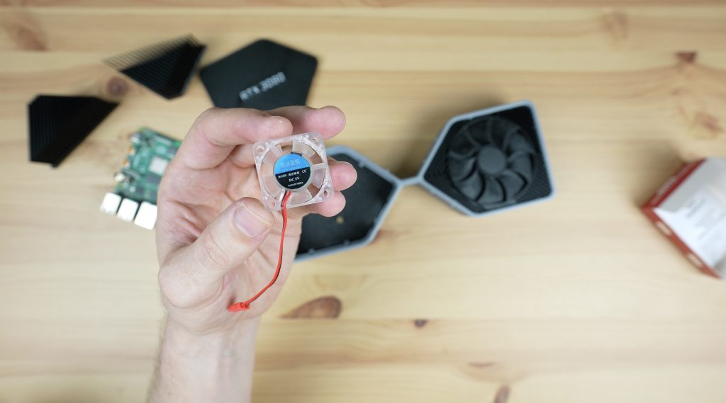
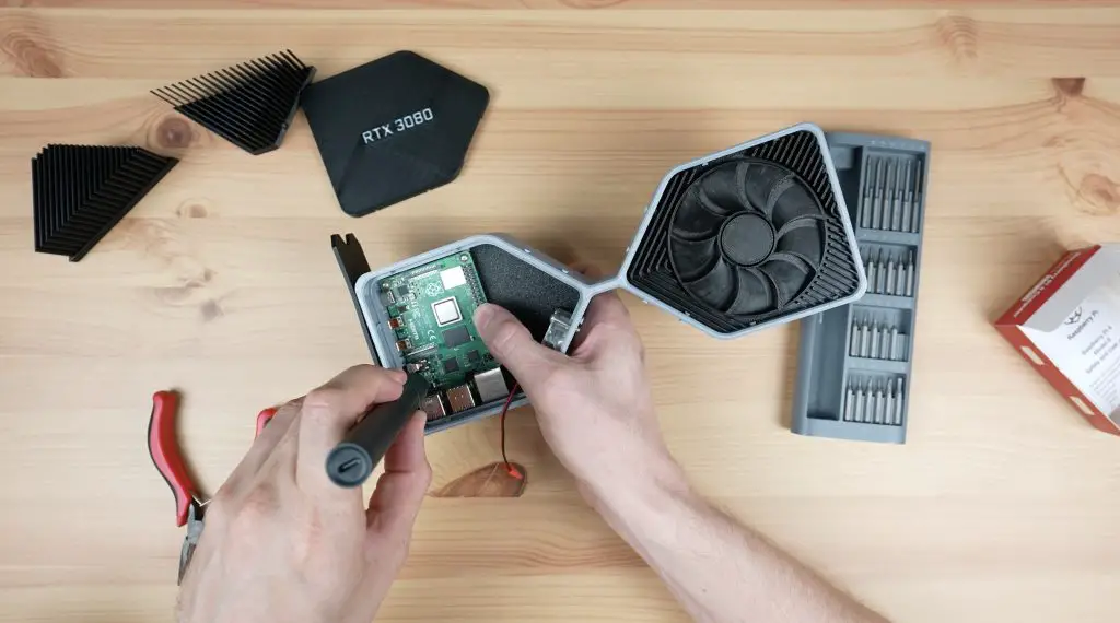
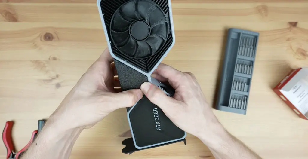
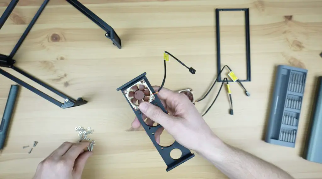
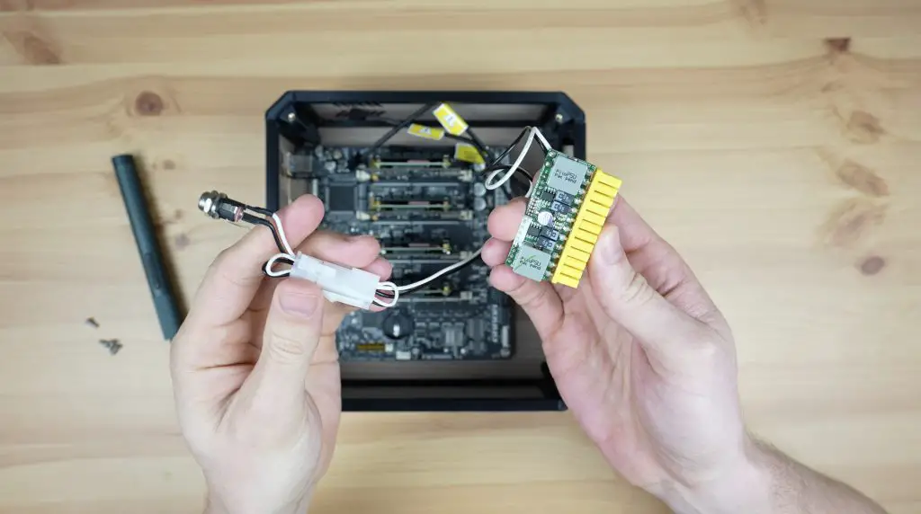
Before we add the side heatsinks, we need to mount the fan. This is just held in place with four M3 button head screws and is oriented to pull air into the enclosure.
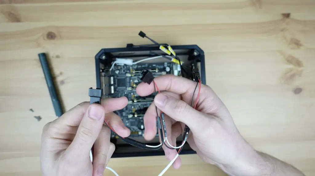
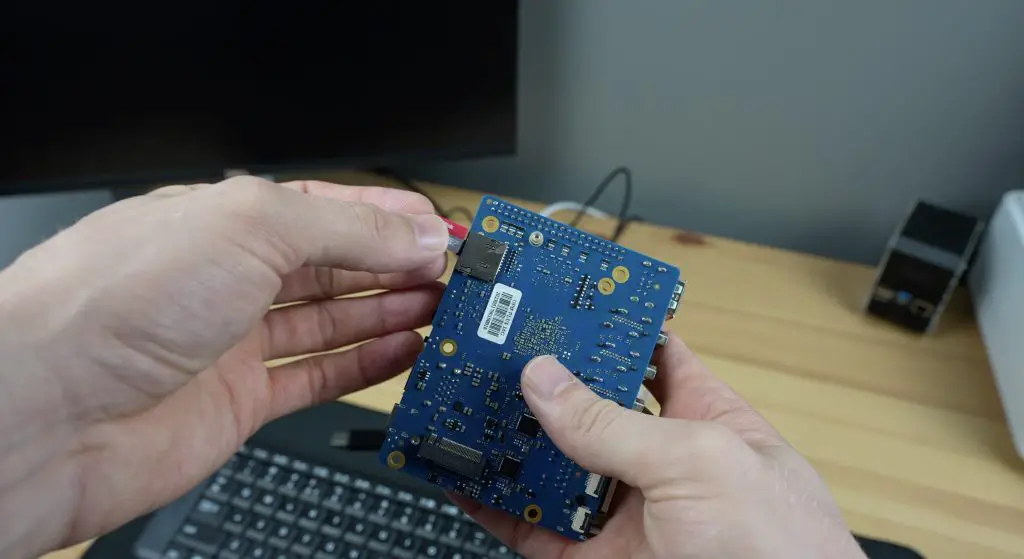
Now we can mount the Pi on the brass standoffs and secure it with some M2.5 screws.
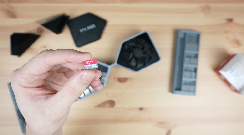
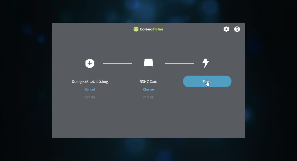
Before doing this, install your microSD card with your OS image flashed to it. I forgot about this and had to remove the Pi again as you’ll see later on.
Then plug the fan into 5V and GND. If you’ve got a fan with separate pins on the plug (mine is a combined double-pin plug) then you can plug the fan into GND and 3.3V instead and it’ll run quieter.
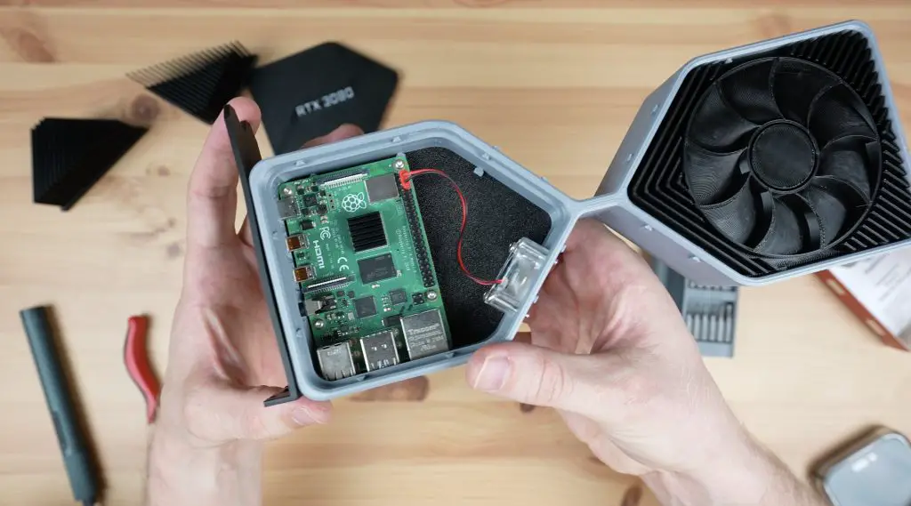
And lastly, having forgotten about the microSD card, we can remove the Pi again, add our card with the OS image and then put it back in and close up the top cover plate.
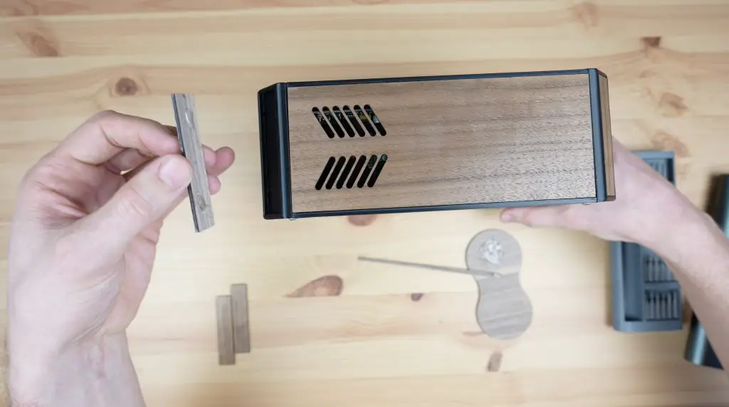
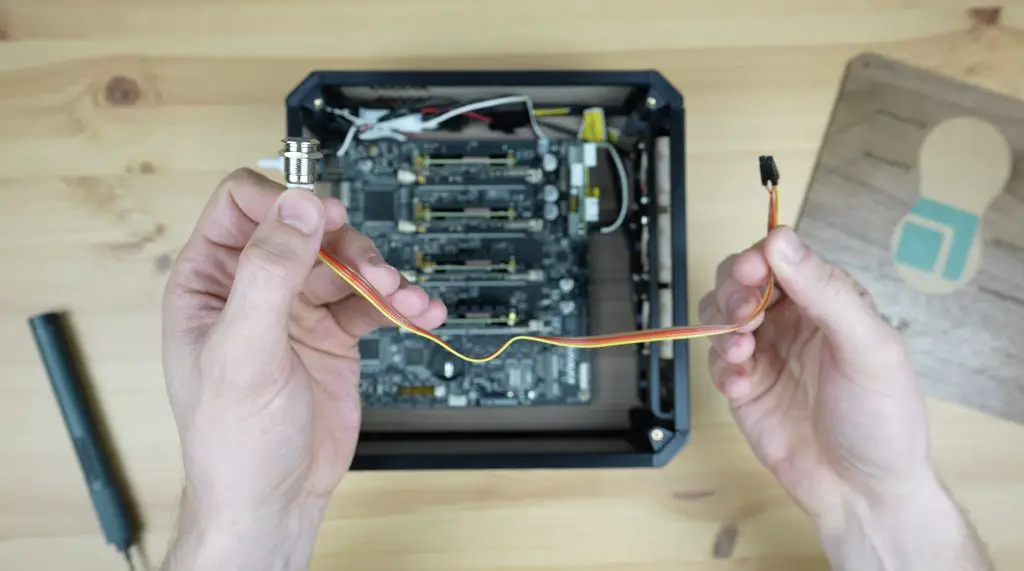
Then we need to snap the side heatsinks into place.
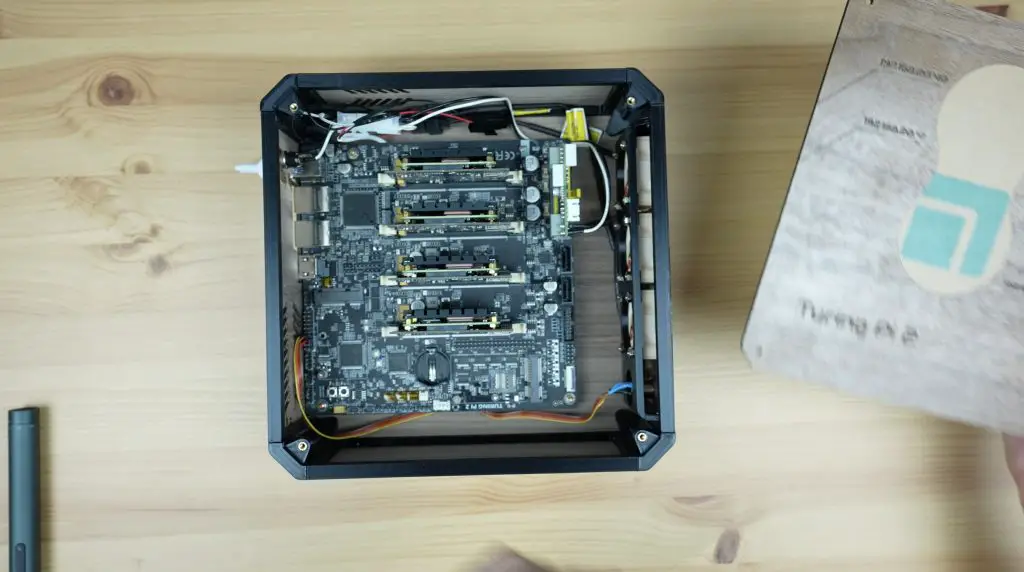
And that’s my GPU computer complete, now let’s plug it in and try it out.
First Boot & Gaming On My RTX3080 Graphics Card
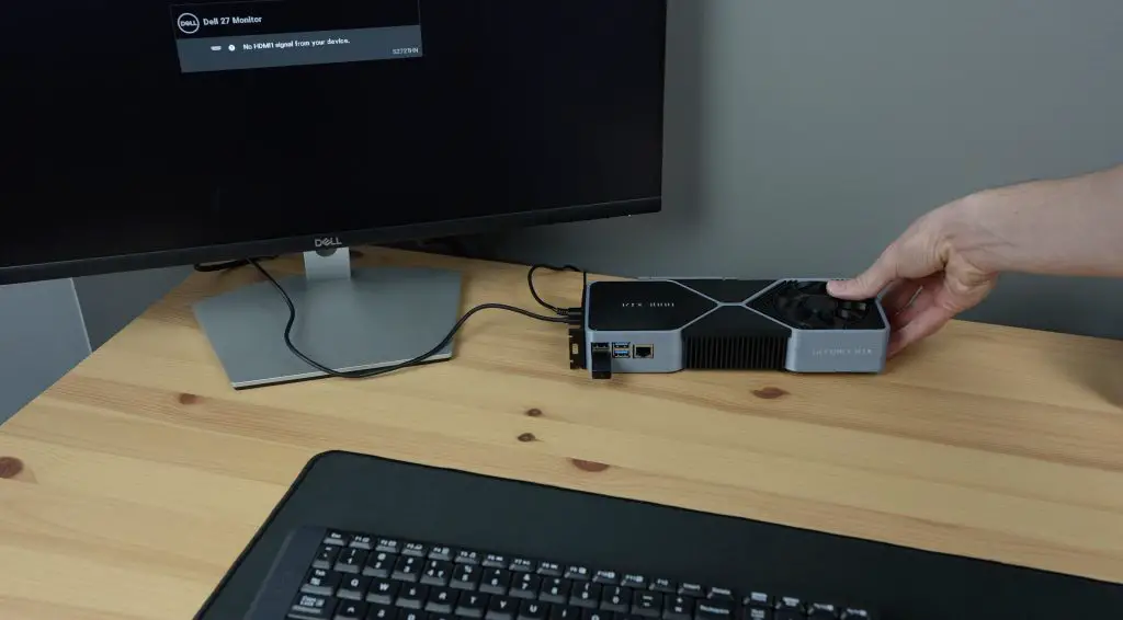
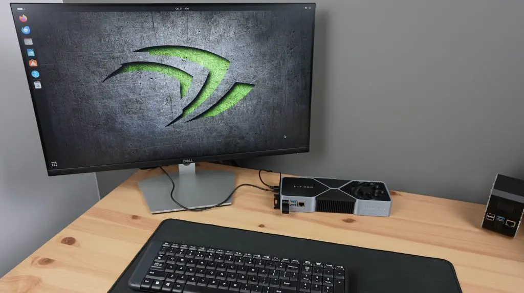
To boot up my RTX3080 graphic card computer, I need to add a power adaptor, plug in a monitor and add a keyboard and mouse.
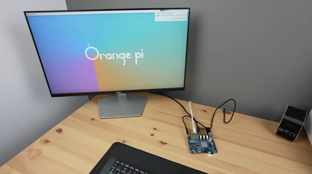
The first boot takes a bit longer to work through but once it has booted up, you’ll then have a fully functional graphics card computer.
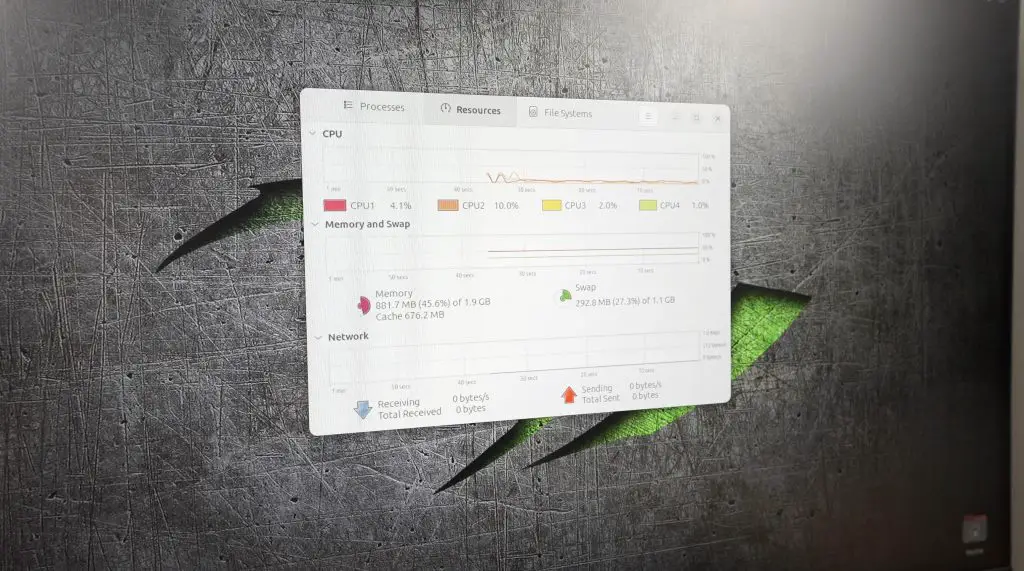
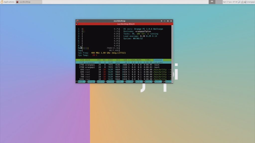
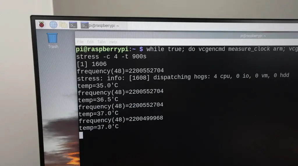
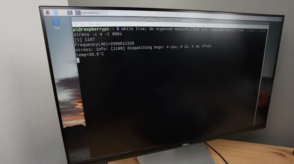
I’m running Ubuntu on the Pi. This does seem to be a bit more resource-intensive than Raspberry Pi OS but still runs reasonably well. I’ve also overclocked the Pi to 2Ghz.
My graphics card computer has actually got a lot of benefits. It is still able to output 4K and it does so using just 3-4W, which is almost a hundred times less than a real 3080 would. I can even run it from a power bank.
It takes up a fraction of the desk space that a full-size desktop computer would.
It’s got no motherboard to fall out of during shipping or transport.
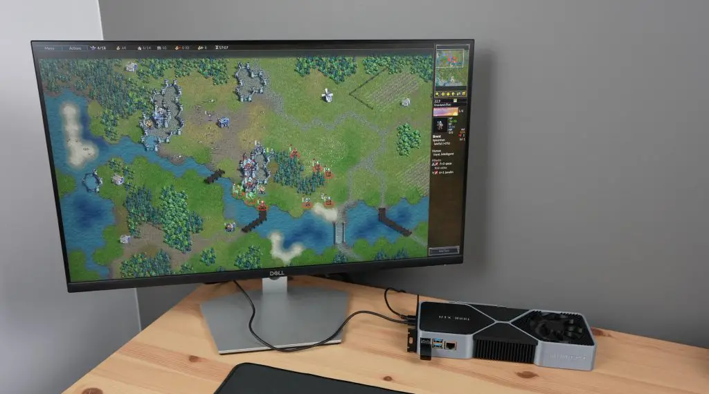
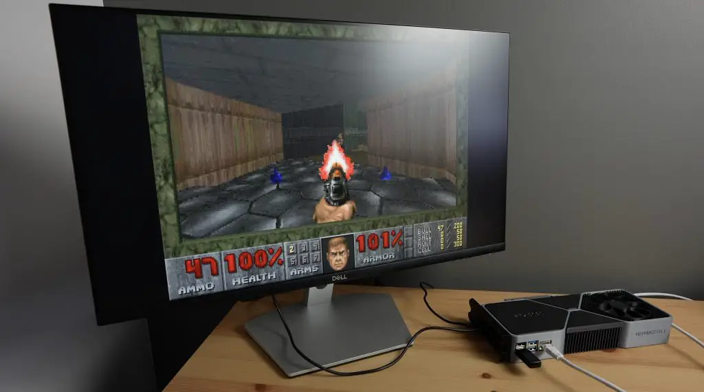
And I can still game on it, although granted the gaming quality and framerate is quite a bit lower than what you’d get from a 3080.
Super Tux Kart – Very low FPS, not playable unless the Pi is significantly overclocked.
Doom – Runs well, a bit more involved to install and find levels for but easy to play.
Let me know what you think of my improved RTX 3080 gaming graphics card in the comments section below and if you have any suggestions on how I can further improve on it.
A few weeks ago I published a project on the controller that I designed for a PET bottle recycler that I’ve been working on. I’ve now completed the rest of the design and at the end of the project, I’m going to use it to turn a few old PET bottles into a new case for my Raspberry Pi.
Let me start by saying that the concept for a PET bottle recycler is not something that I came up with, there are a number of other designs (like the ReCreator 3D) for these recyclers available online already. I liked the concept but couldn’t really find one that suited my needs, so I decided to make my own.
Here’s my video of the build, read on for the written guide;
What You Need To Make Your Own PET Bottle Recycler
Some of the above parts are affiliate links. By purchasing products through the above links, you’ll be supporting my blog, at no additional cost to you.
Designing The PET Bottle Recycler
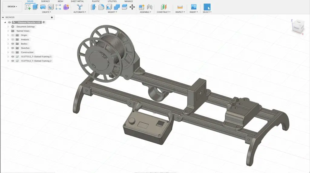
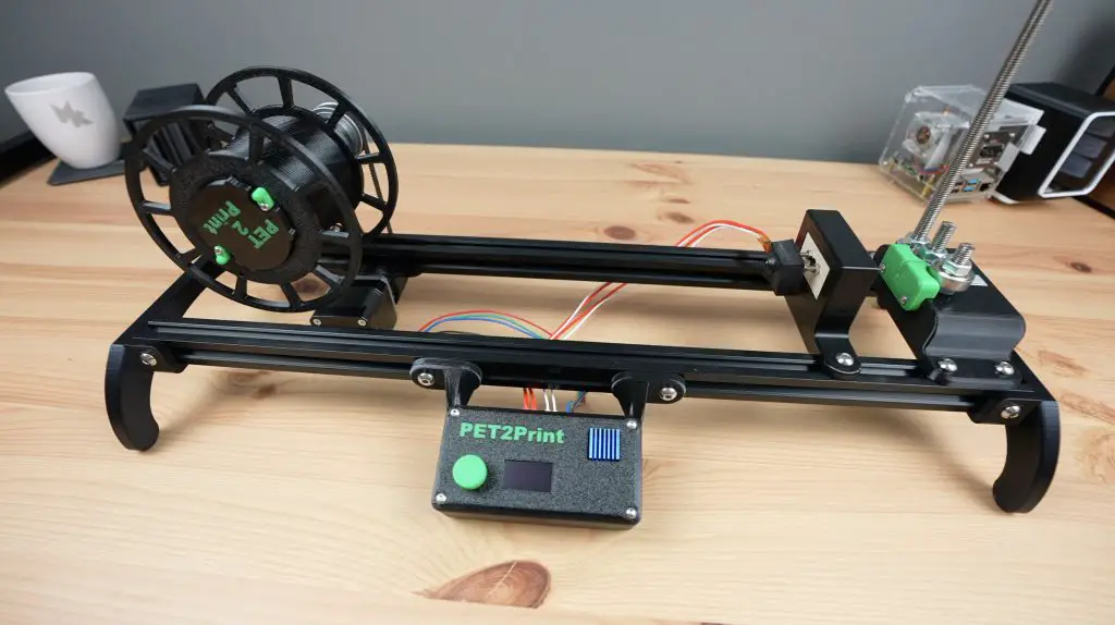
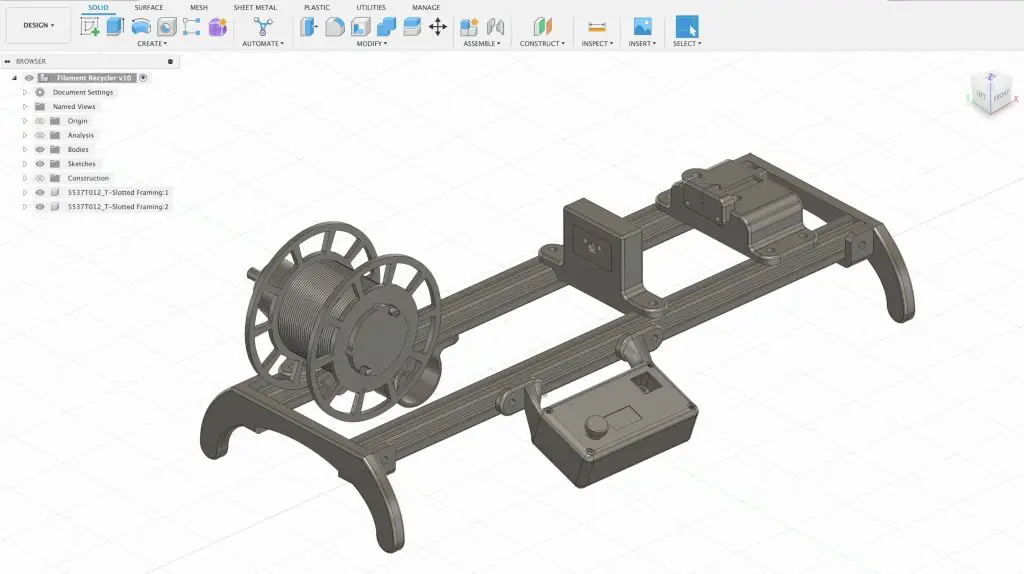
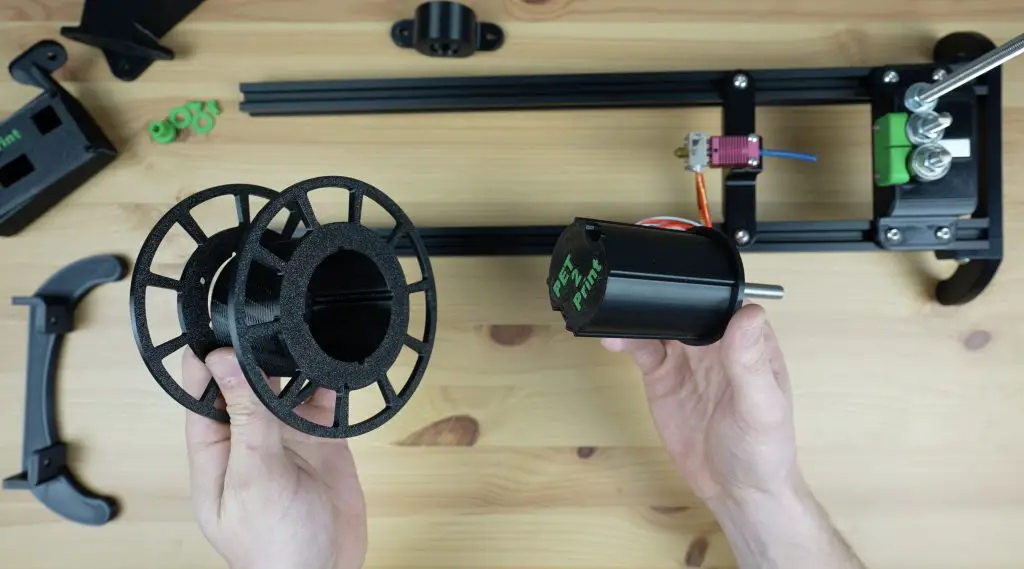
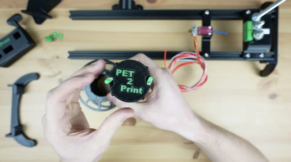
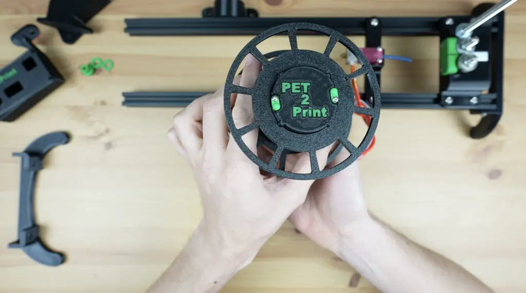
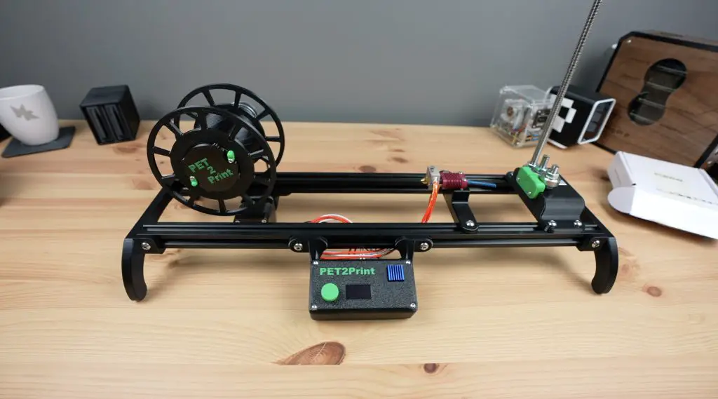
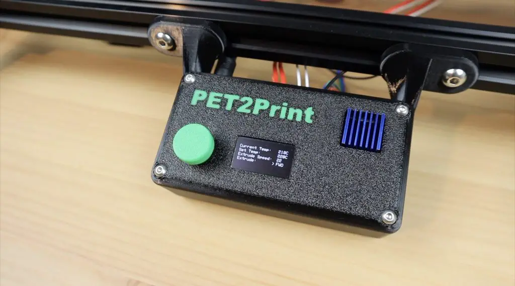
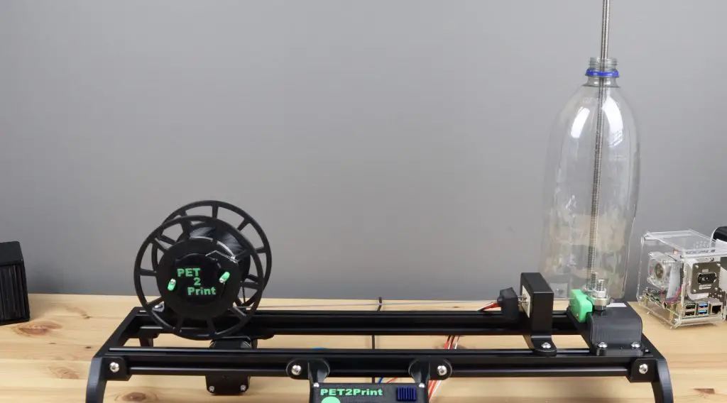
There are four main elements to the PET bottle recycler, which I’ve named PET2Print.
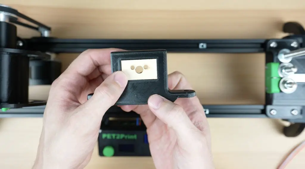
Starting from the bottle side, we’ve got a cutter that cuts the bottle into an even-width continuous strip.
Then we’ve got the hot-end which the strip is pulled through to partially melt and convert it into the size and shape for filament.
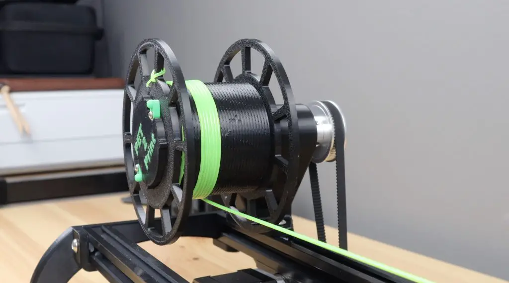
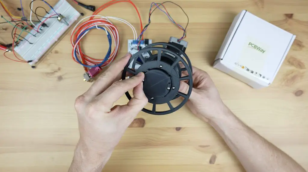
Then there is the reel which pulls the filament through the system and stores it for printing.
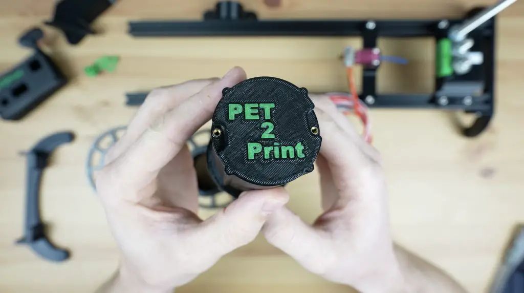
Lastly, we’ve got the controller on the front which controls the hot end temperature and the reeler motor.
The device doesn’t fully melt the PET strip, it just softens it enough to be folded over into a cylindrical shape that is the same 1.75mm diameter as common 3D printer filament.
I started out by 3D modelling the design in Fusion360. I designed all of the 3D printable components and modelled some of the main bought-out elements to get the general shape and design right.
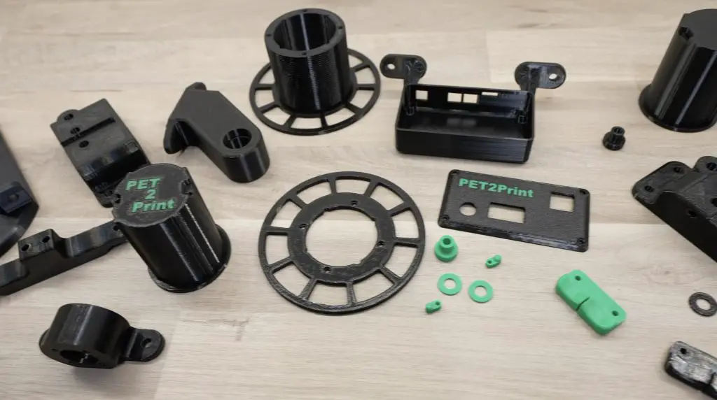
Then came a lot of 3D printing. I printed the parts out in PETG for added strength and I had to make adjustments and redesign some of the parts until I was happy with them.
Assembling The PET2Print
With all of the parts printed, we can start assembling the PET bottle recycler. We’ll again start on the bottle side with the cutter.
Assembling The Bottle Cutter
There are two main 3D printed parts for the bottle cutter, the base which holds the cutting mechanism and bottle support, and then the guide which just keeps the strip in the same orientation through the cutting bearings and when it feeds into the hot end.
To join the two pieces, we need to add some M3 threaded brass inserts to the side of the base, which we’ll melt into place using a soldering iron.
Before we screw the guide into place, we need to add the cutting mechanism. This uses two 608 ball bearings to cut the filament. These are really cheap and easy to get as they’re the same size bearings that are used for skateboard wheels and fidget spinners.
To turn them into a cutter, we need to sharpen one face of each bearing by grinding it flat. I did this on a bench grinder to make sure they’re kept square. You can also use a sanding disc or grinding disc on a grinder.
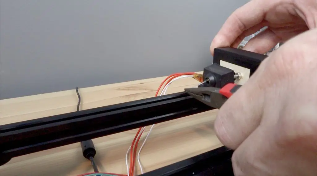
We then need to epoxy two M8 studs that are approximately 60mm long into the base to mount the bearings on. You can cut the M8 threaded rod using a cutting disc on a grinder, a Dremel or a hacksaw.
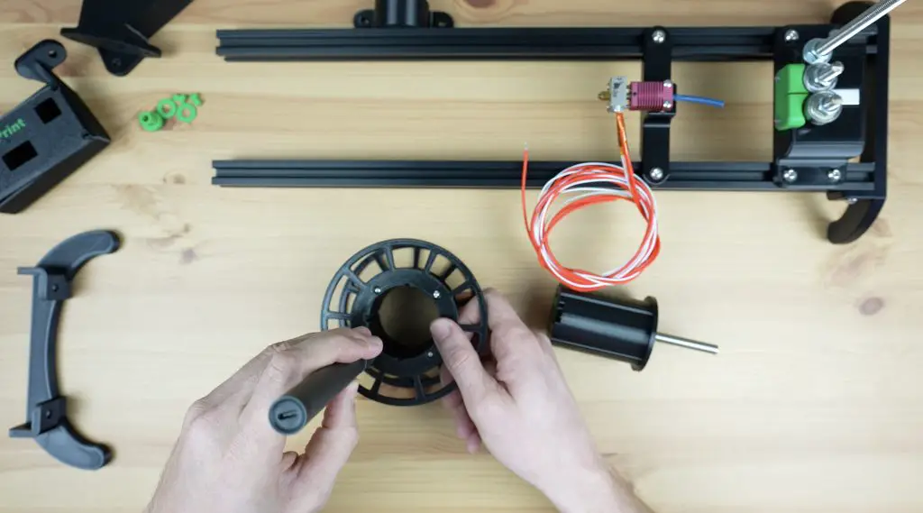
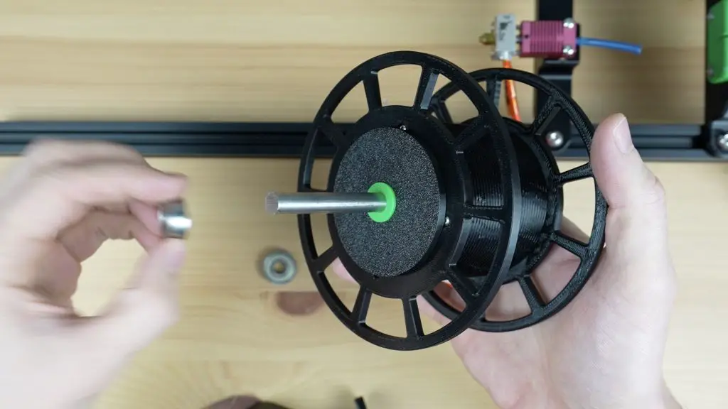
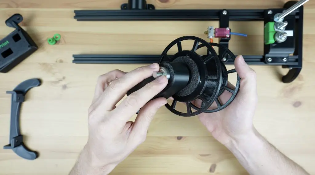
While we’ve got some epoxy mixed up, I’m also going to epoxy the 8mm shaft into the reel holder to use later.
Once the epoxy has cured, we can mount the bearings onto the studs.
We also need to add a metal strip underneath the bearings, this stops the bottle from quickly wearing out the printed base. The strip will need to be trimmed from a piece of aluminium flat bar so that it fits into the cavity in the holder.
A small washer is used under the first bearing. The bearing then goes onto it with its flattened or ground face up, so that it doesn’t rub on the base. A nut holds it in place. We then add a nut to the second stud, then the bearing with the ground face down, just at the right height to contact the face of the first. A second nut holds the second bearing firm against the first bearing and the nut below it.
We can then screw the guide onto the front of the base with some M3 x 8mm button head screws.
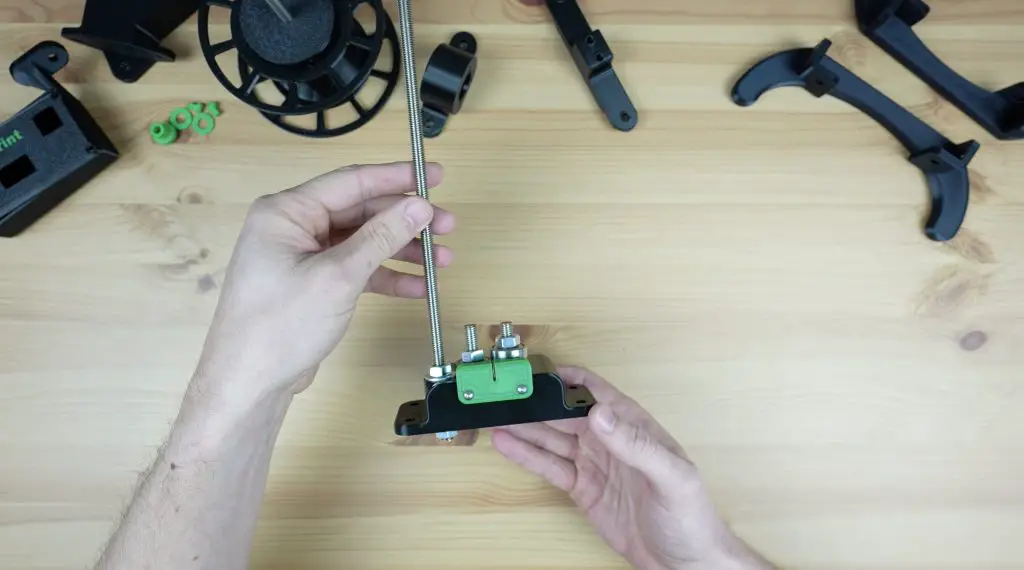
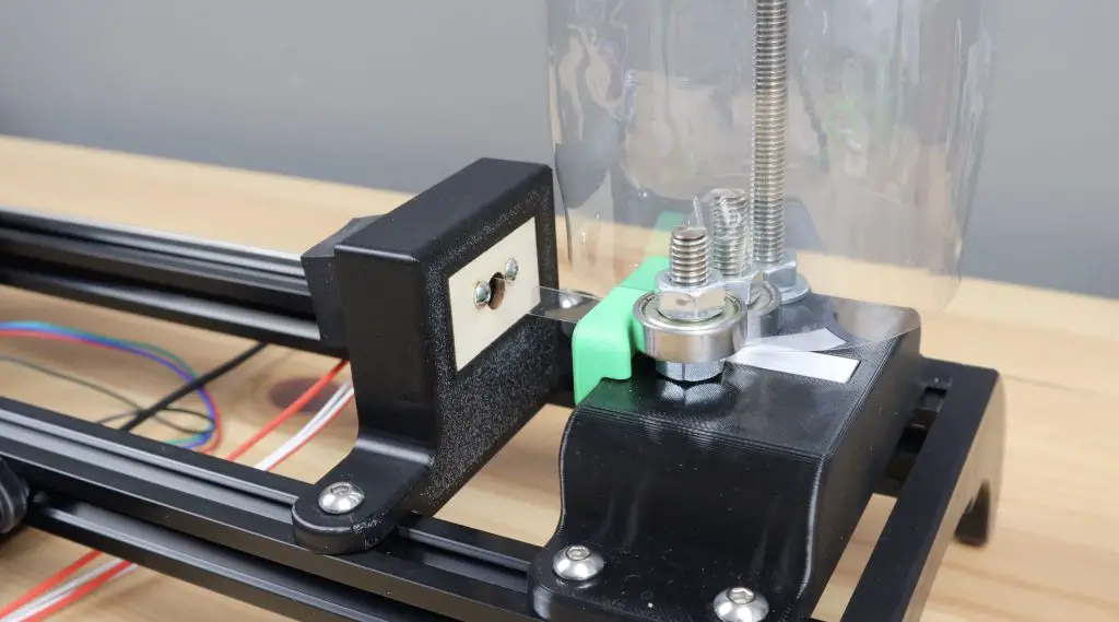
To finish it off, let’s also add a M8 rod for the PET bottle stand. You can make this from the leftover length of M8 threaded rod, it needs to be long enough to hold the tallest bottle that you’ll use on the PET 2 Print (around 300-400mm). This will hold the bottle upright to feed the end into the cutter and it is held in place with a nut and washer on each side of the base.
And that’s the cutter complete and ready to be mounted onto the stand.
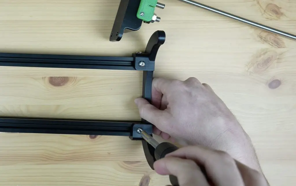
Assembling One Side Of The Stand
The stand consists of two 500mm lengths of 2020 aluminium v-slot extrusion and two sets of legs, one on each end. These are mounted with some M5 v-slot nuts and M5 x 10mm button head screws.
We can add one set of legs onto one end and then slide the cutter into position.
First Attempt At The Hot End
The hot end is a really simple part of the recycler, but it actually turned out to be one of the more tricky parts to get right. I’m going to skip through this initial design because there were a couple of things I didn’t think through when I designed it and it didn’t work.
Because the nozzle is going to be over 200 degrees celsius, we need a way to stop the heat from reaching the 3D-printed plastic holder. I thought I could use the heat break on the current hot end assembly, but I overlooked the fact that this meant that the strip wouldn’t fit into it. So I was back to the drawing board shortly after finishing it.
Assembling The Reeler
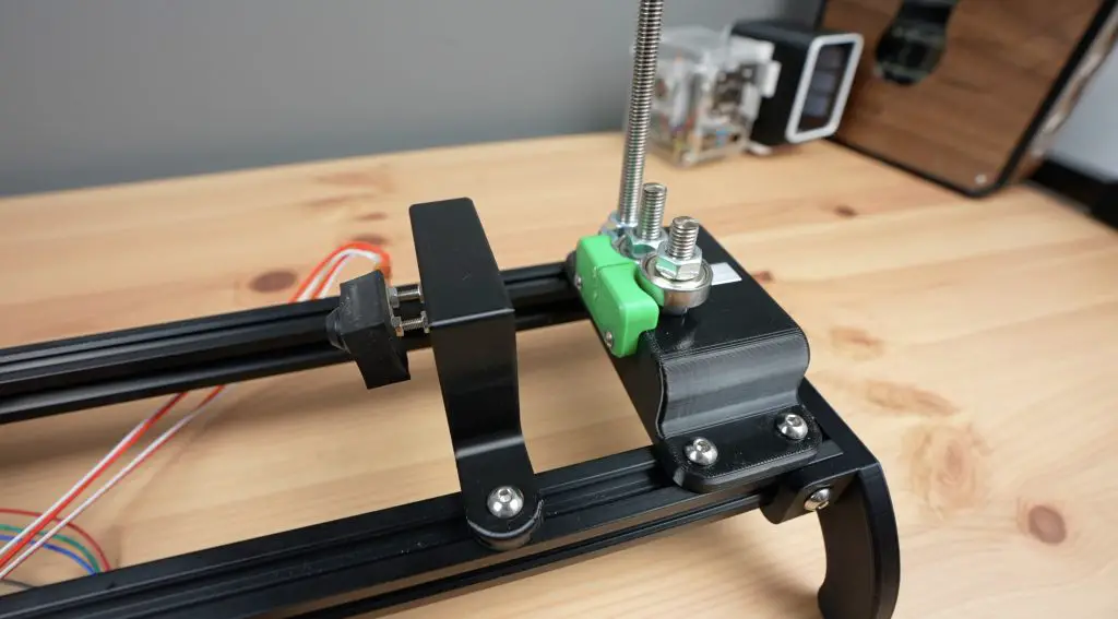
Next let’s move on to the most complicated part of the recycler, the reeler. This is the part that is driven by a stepper motor to pull the filament through the cutter and hot end.
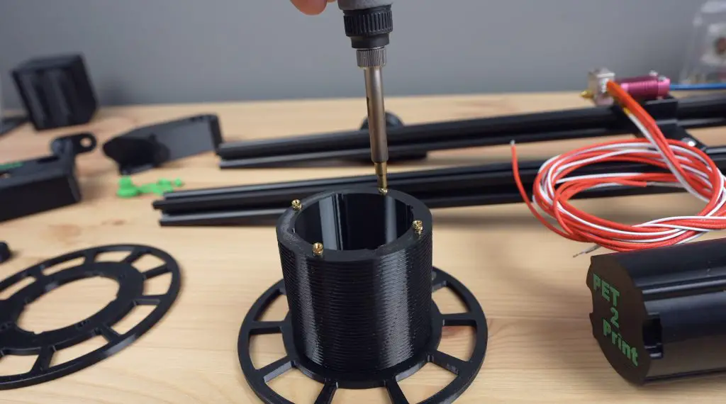
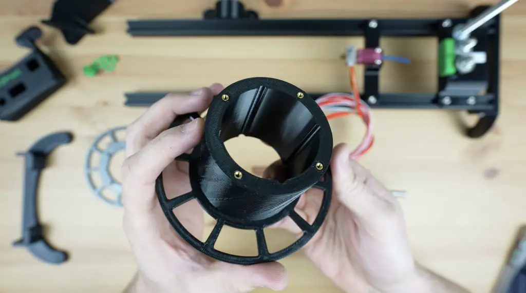
We’ll start by making up the reel.
The reel is something that I’ve changed quite a lot from the others I’ve seen online. On most other machines, the reel is fixed on both sides and you need to unwind the filament from the reel once it’s done. I wanted to avoid this, so I made the reel removable which makes it much easier to get the completed filament off of afterwards.
To finish the reel off, we need to melt some M2.5 threaded brass inserts into one half of the reel for the opposite end to screw onto. This is split to make it easier to 3D print without requiring supports.
We also need to add some inserts to the other end of the reel holder for the small catches that hold the reel in place while it is running.
Then we can screw the reel parts together with some M2.5 x 6mm screws and the catches with some M2.5 x 12mm screws to finish them off.
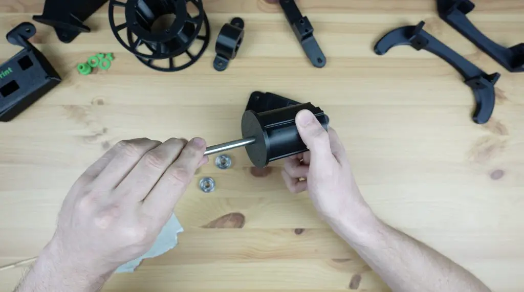
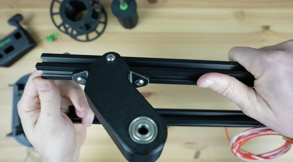
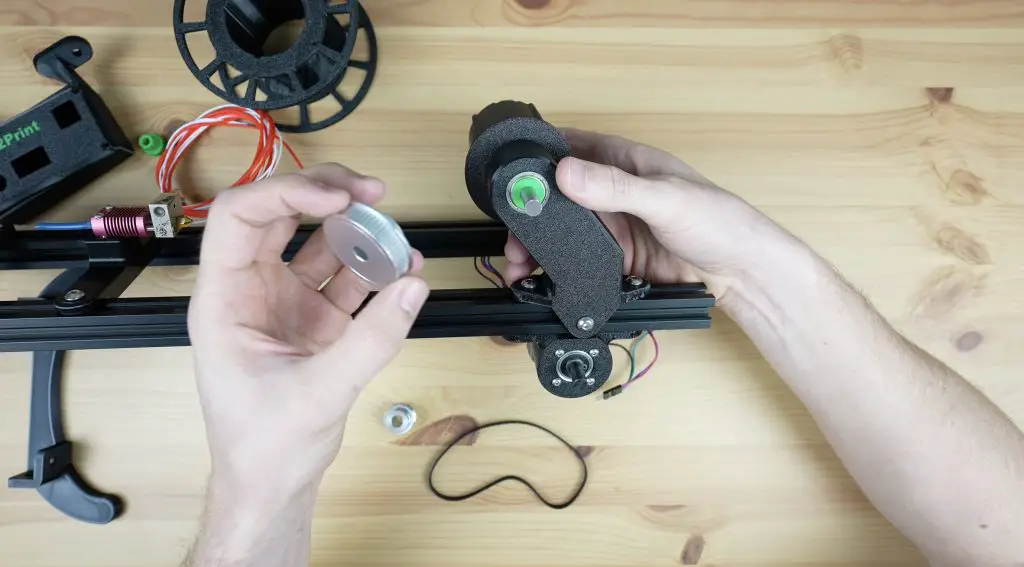
Next let’s press another two 608 size bearings into the reel stand, one on each side. We’ll use an 8mm shaft as a guide to keep them aligned while pressing them into place.
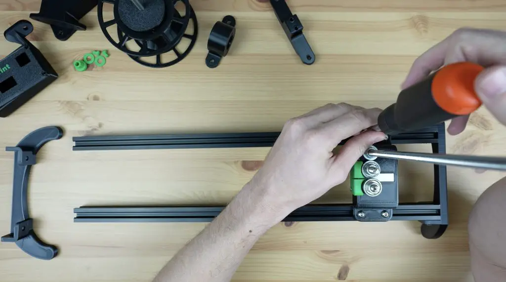
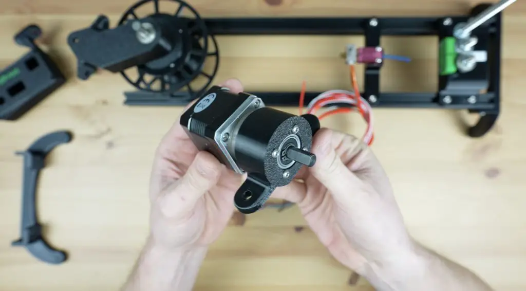
Next, let’s mount the motor onto its holder using four M3 x 8mm button head screws.
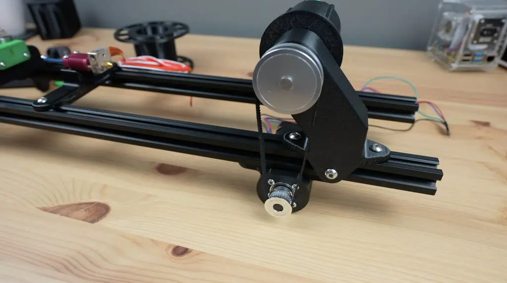
Then we can mount the base onto the top of the v-slot extrusion.
And the motor holder onto the underside.
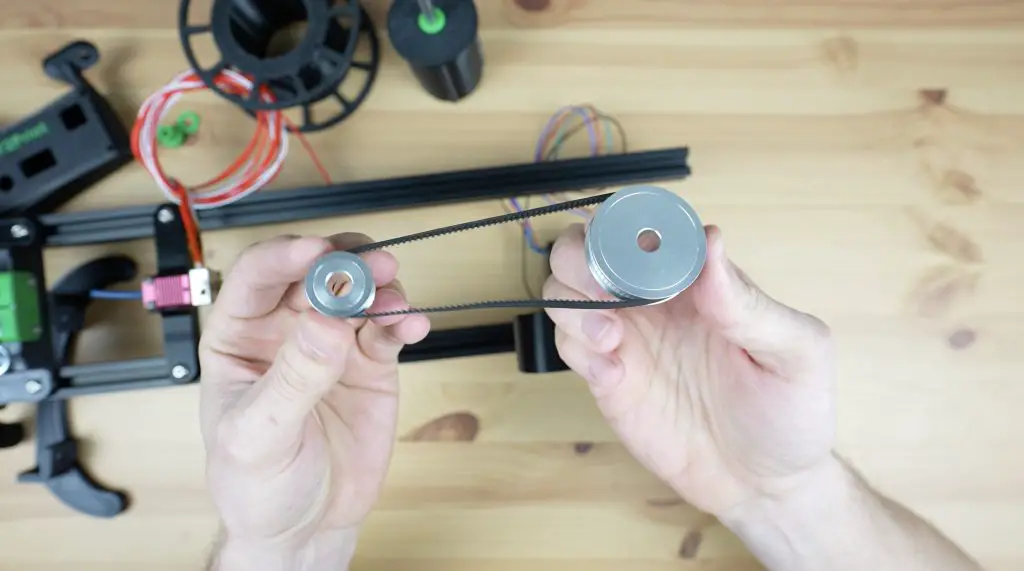
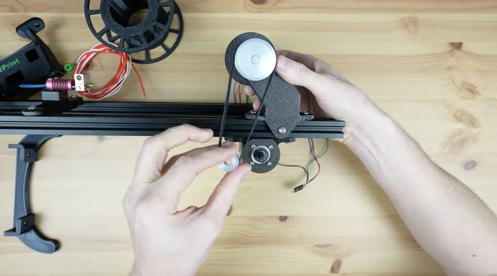
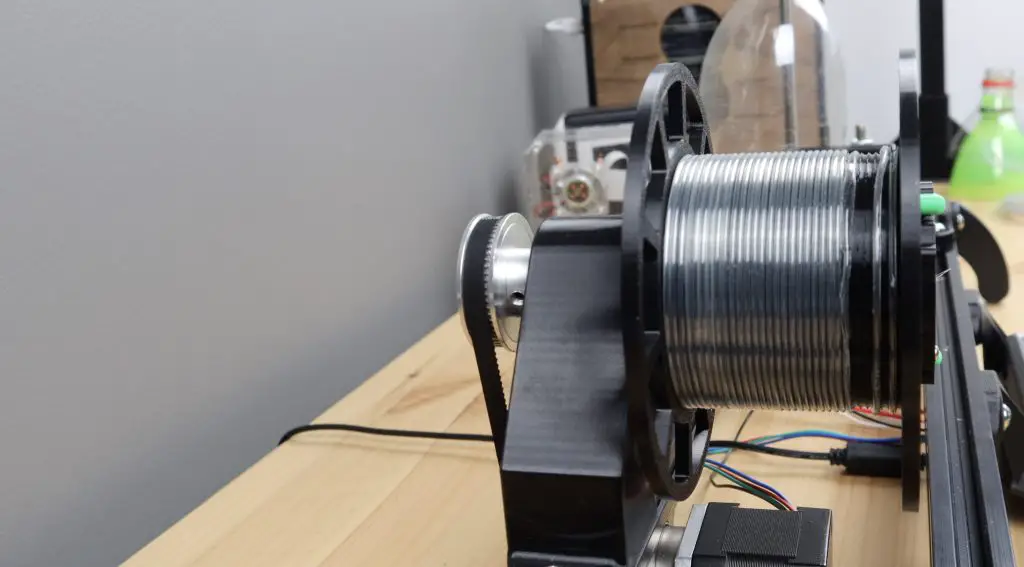
The reel is driven by the motor through a GT2 belt and pulley system on the back.
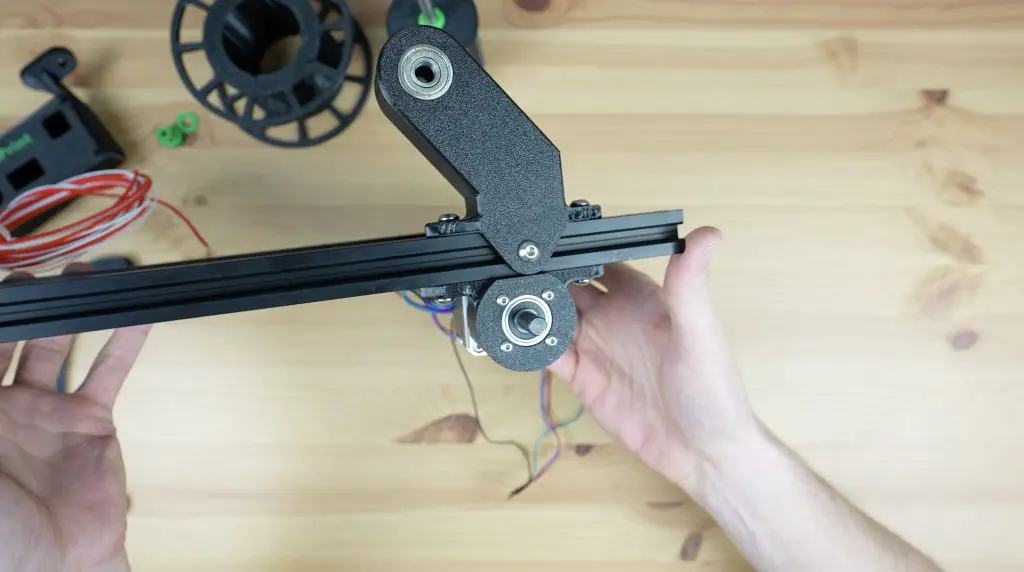
So we can push the reel’s shaft through its base with a spacer between it and the bearing, then another spacer on the opposite side. We then add the 60-tooth pulley to finish it off and the grub screw holds it in place. A 30-tooth pulley is pushed onto the motor shaft, with a belt connecting the two. Once complete, the shaft on the reeler can be trimmed to be flush with the face of the 60-tooth pulley.
The belt is tensioned using the relative movement between the reel base and the motor holder, pulling them further apart puts more tension on the belt. This needs to be fairly well-tensioned but shouldn’t put enough stress on the components to bend or distort any of the 3D printed parts.
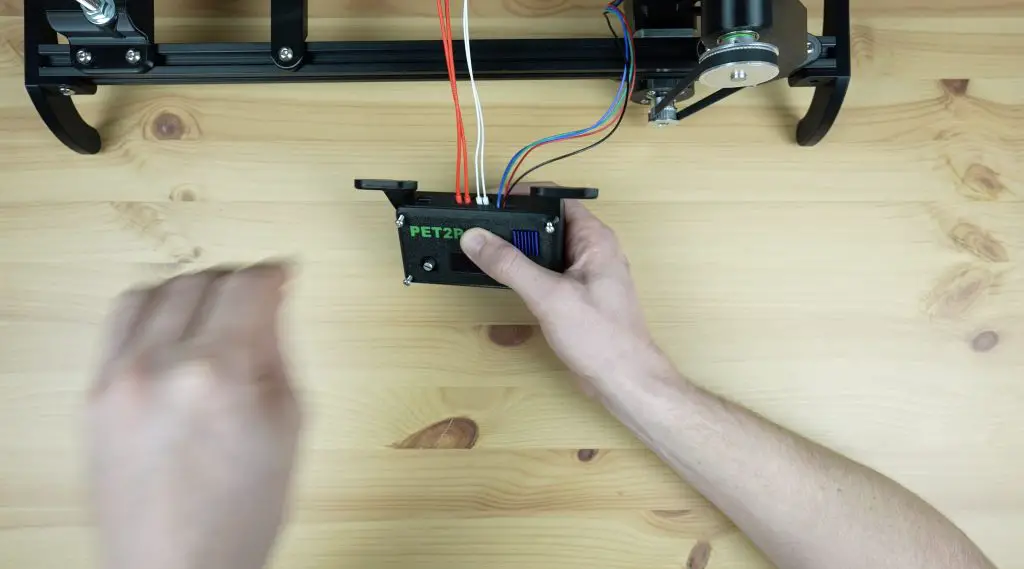
Assembling & Programming The Controller
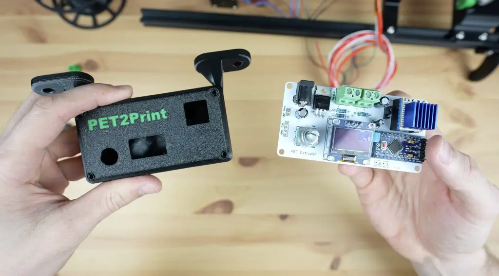
Now that we’ve got the mechanical parts in place, we need to add the controller.
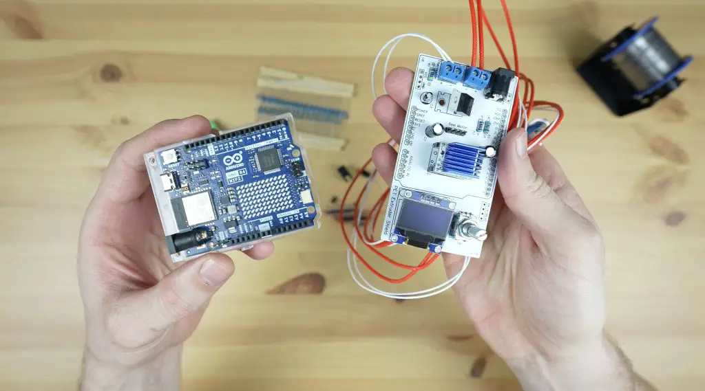
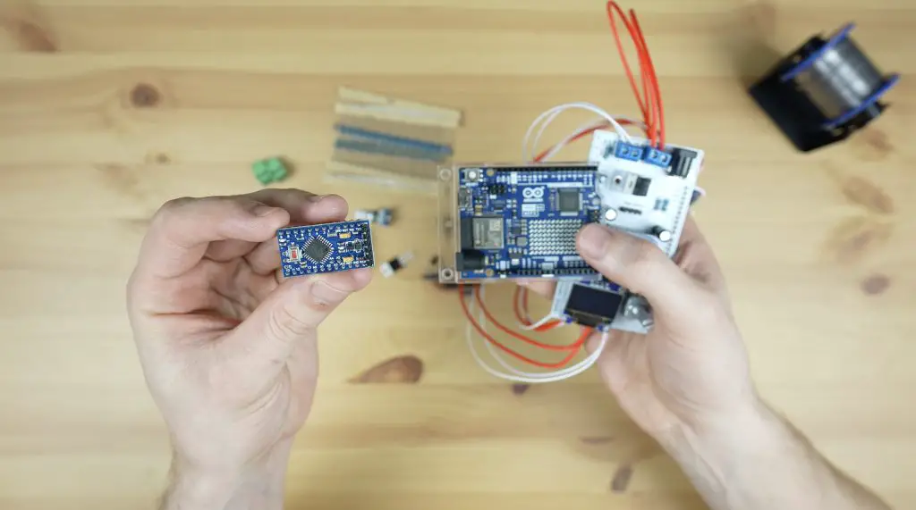
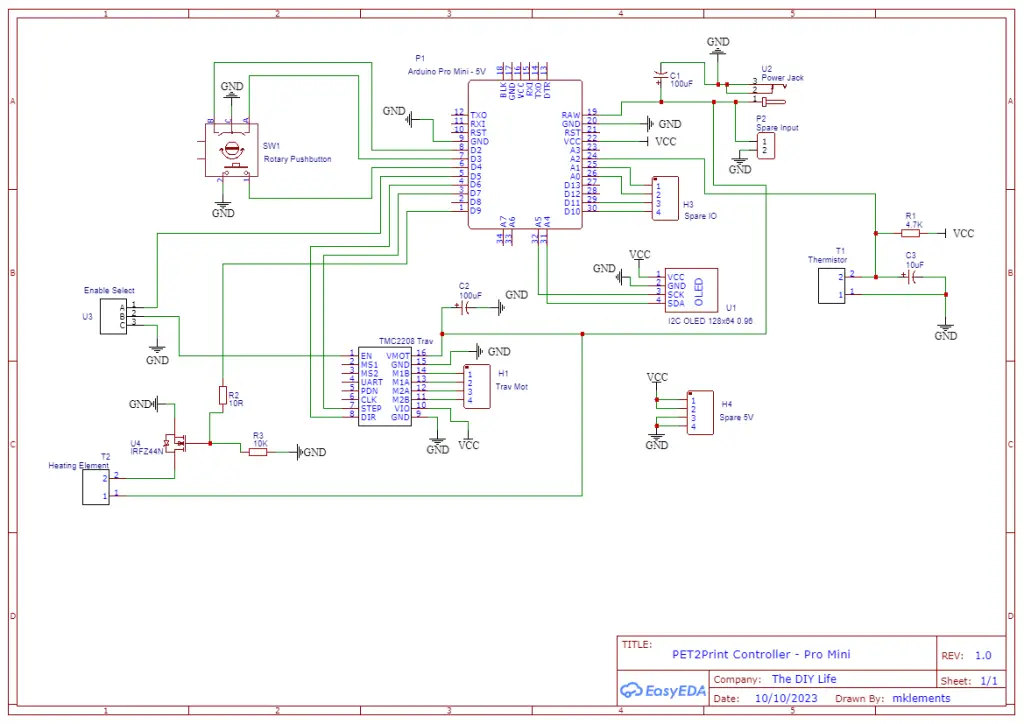
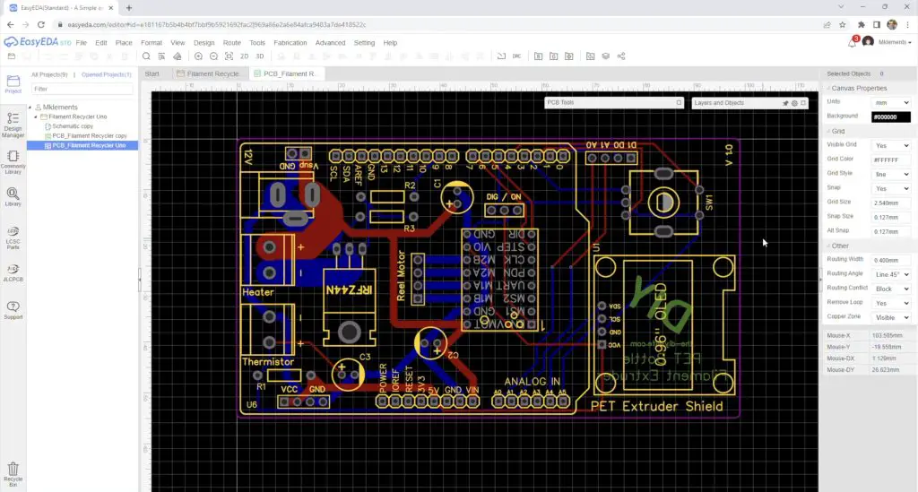
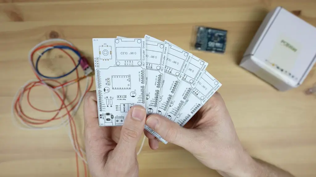
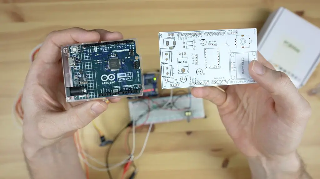
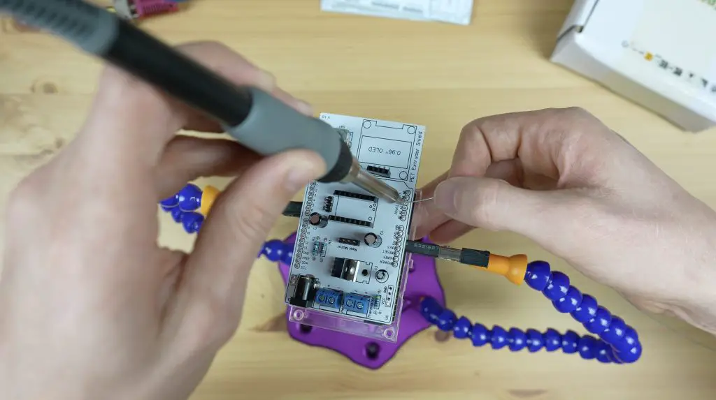
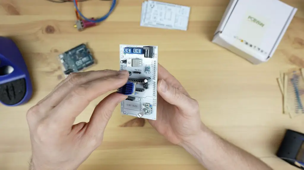
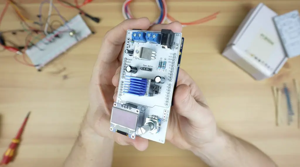
If you read my previous design and build of the controller, I ended that off by saying that I wanted to make it a bit more compact. It was designed as a shield for an Arduino UNO, but by using an Arduino Pro Mini, we can make it much smaller.
So I designed a new PCB that swapped the UNO out for a pro mini and brought the components a little closer together.
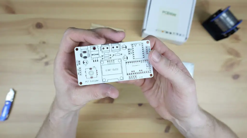
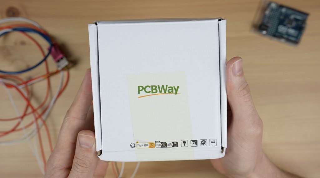
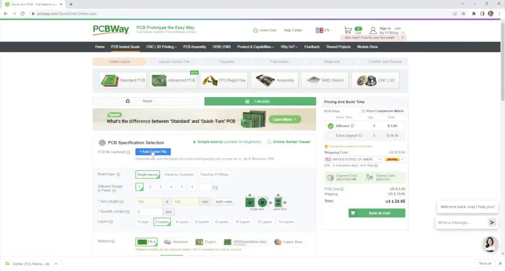
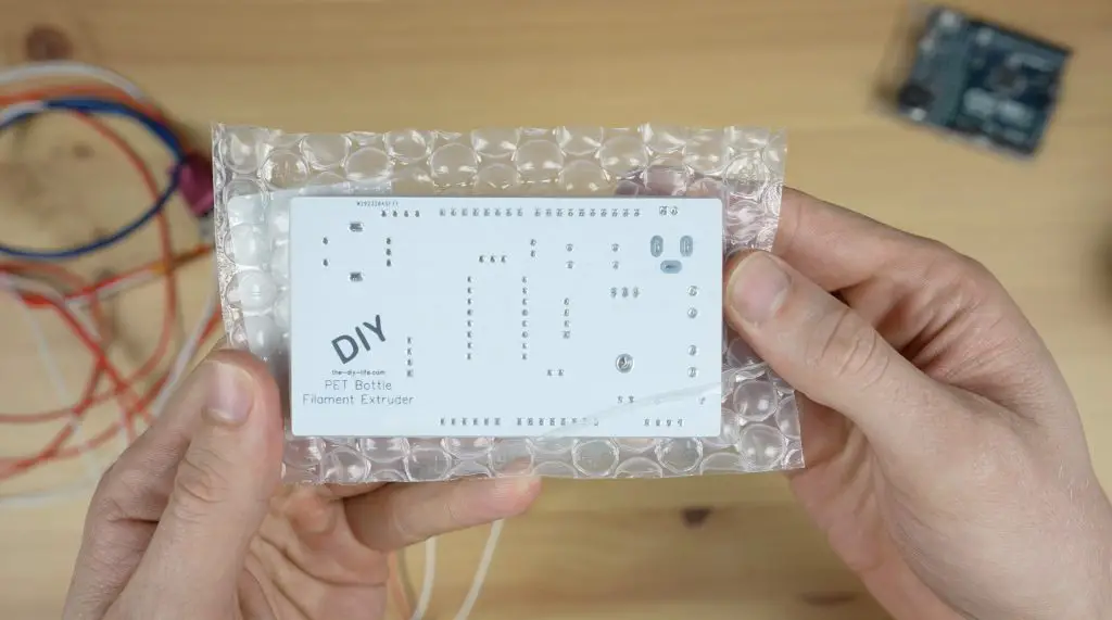
PCBWay then made them up for me in the same colour scheme as my previous shield.
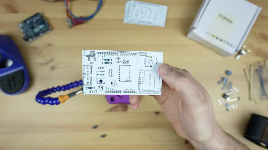
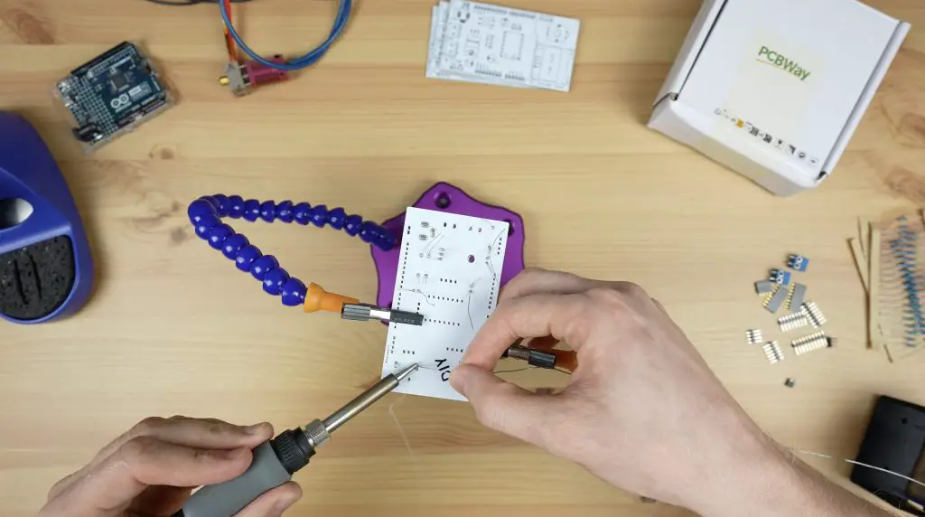
I soldered the components onto the PCB, starting with the smallest and working to the largest, with the Arduino going on last.
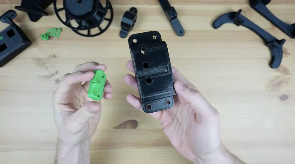
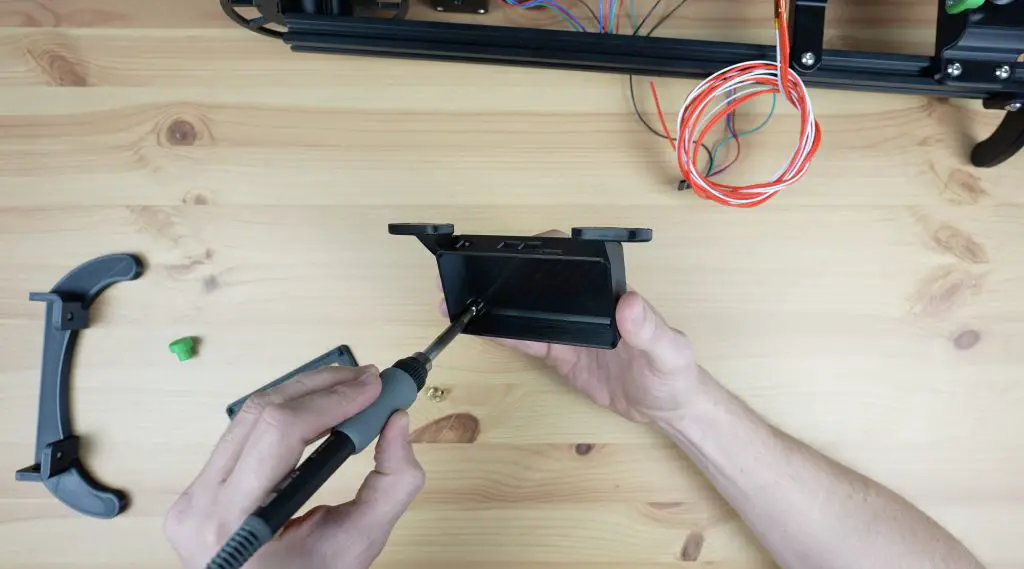
I also 3D printed a housing for the controller, but before we put it into the housing we need to program it and set up the stepper motor driver’s current limit.
Programming The Arduino
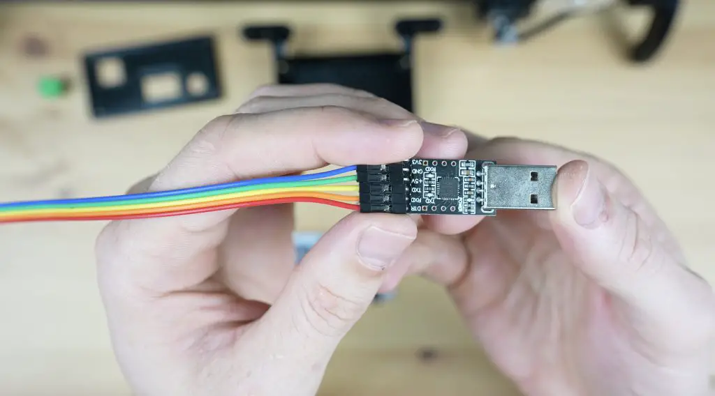
To upload the code to the Pro Mini, we’ll need to use a USB programmer. We just plug this into the Pro Mini and then into the computer to upload the code to it.
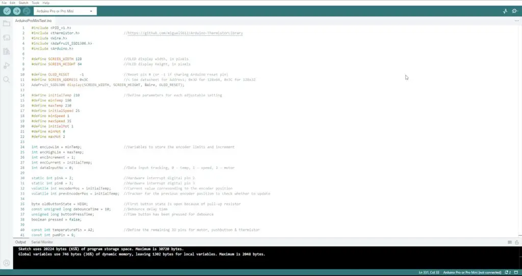
Make sure that you select the “Arduino Pro or Pro Mini” board type. Also check that you have the “Atmega328P (5V, 16MHz)” processor selected and that your programmer type is set to “USBasp”.
The sketch is available from my GitHub repository so that people can make changes and improvements to it.
Setting The Stepper Motor Driver Current Limit
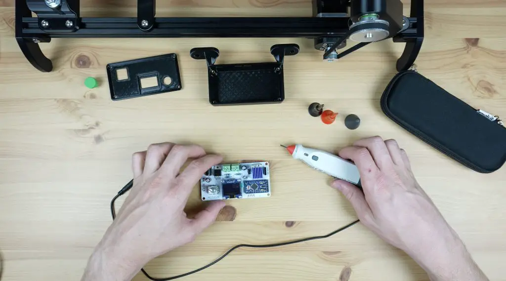
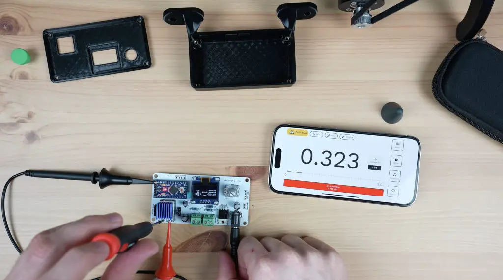
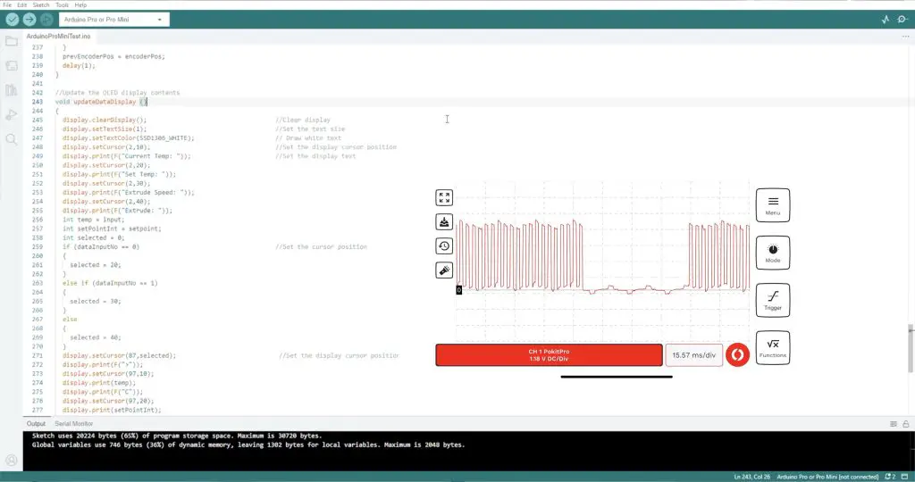
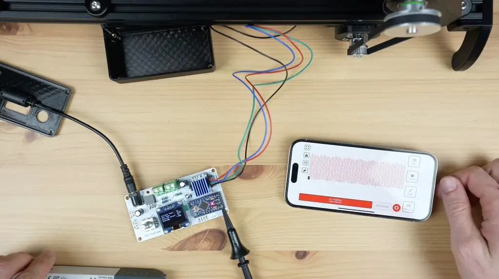
To set the current limit, we need to measure the driver’s reference voltage using a multimeter. I’m using my Pokit Pro multimeter with clamp leads.
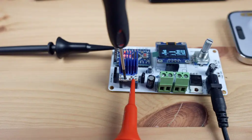
We then adjust the limit using a screwdriver to turn the onboard potentiometer to suit the rated current of the motor, which in my case is the same as the maximum current limit for the driver. So I’m aiming for a reference voltage of exactly 1V.
Display Update Issue
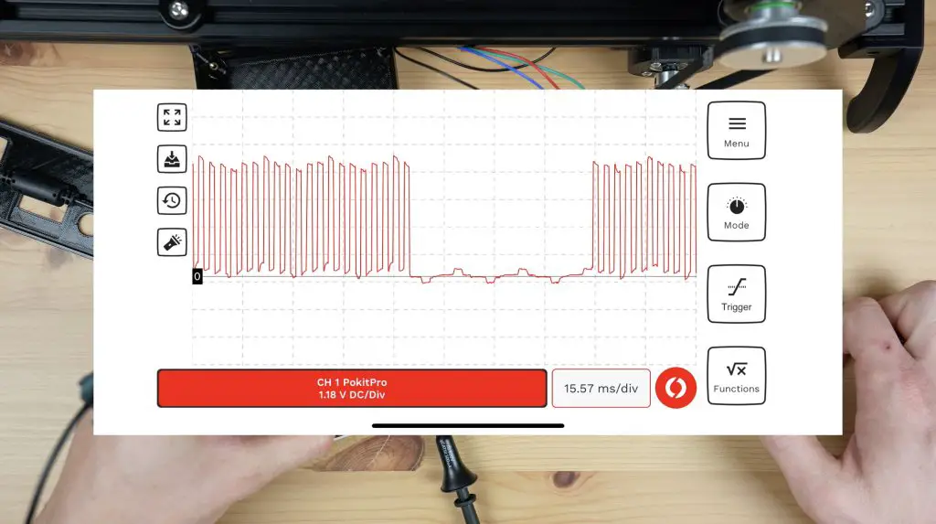
After setting the driver’s current limit and attempting to run the motor, I found another issue. When running the stepper motor, it sounded like it was intermittently skipping steps or stopping and this seemed to get worse if I sped the motor up.
I put the Pokit Pro’s oscilloscope onto the output and found that the Arduino stopped pulsing the stepper motor driver for brief periods of time, which was causing the driver to stop turning the motor.
In working through the code, it seems like this happened each time the display was being updated. It looks like the Arduino takes longer to update the display than the period of time between pulses. So it just stops pulsing the driver while it finishes updating the display, which is obviously not going to work when we need a consistent pulling force. I tried making the display loop faster but didn’t have any luck with this. In the end, I had to modify the code so that it no longer updates the display when the motor is running.
This does limit the feedback on the display during operation, but won’t affect the overall design or functionality. I’ll have to investigate whether I can make the display or portions of the display update more quickly in the future.
In any case, we now get smooth pulses from the Arduino and a consistent motor speed.
Mounting The Controller
To finish off the enclosure, we first need to add some M3 threaded brass inserts into the bottom to screw the PCB to.
The PCB is then held in place with some M3 nylon standoffs which double up as a means to hold the top cover in place.
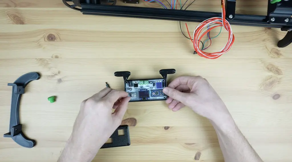
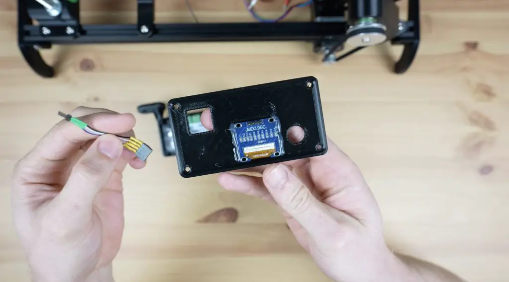
I’m glued the OLED display to the inside of the top cover with some hot glue and I’ll connect it to the PCB with a short ribbon cable.
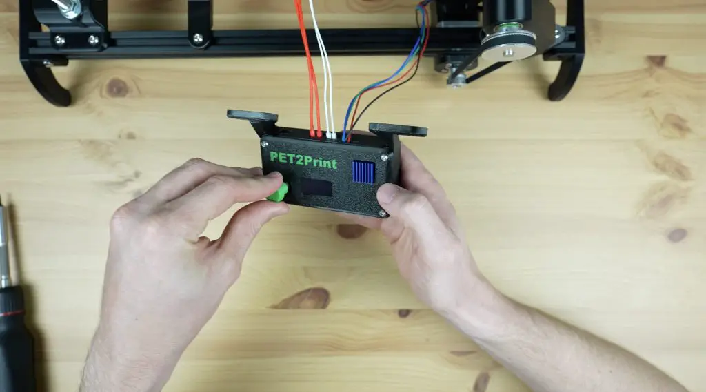
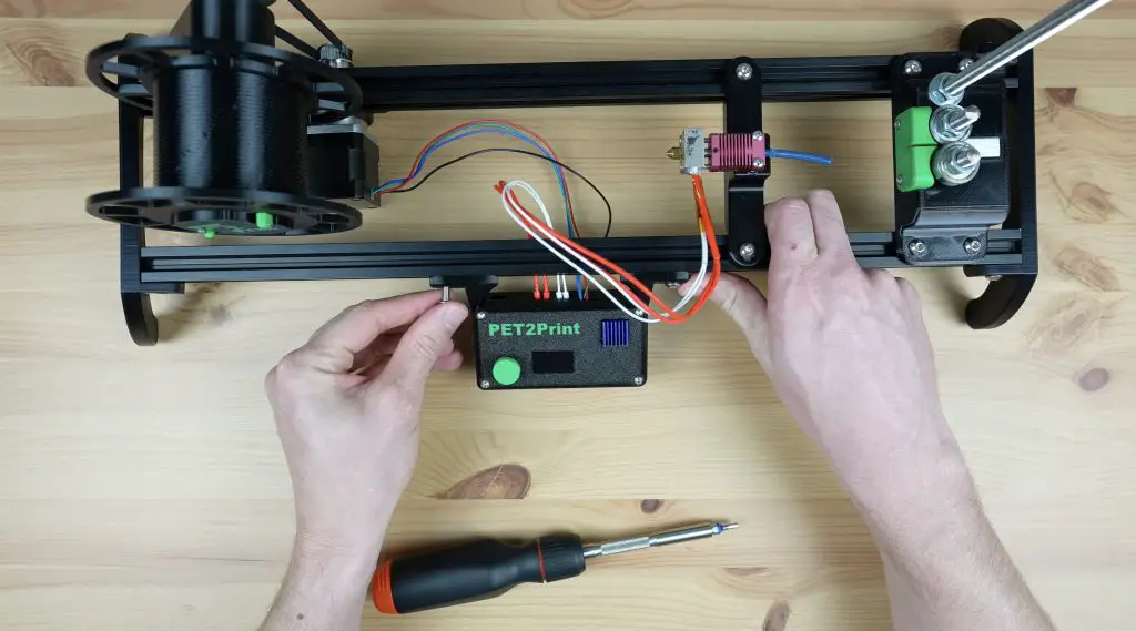
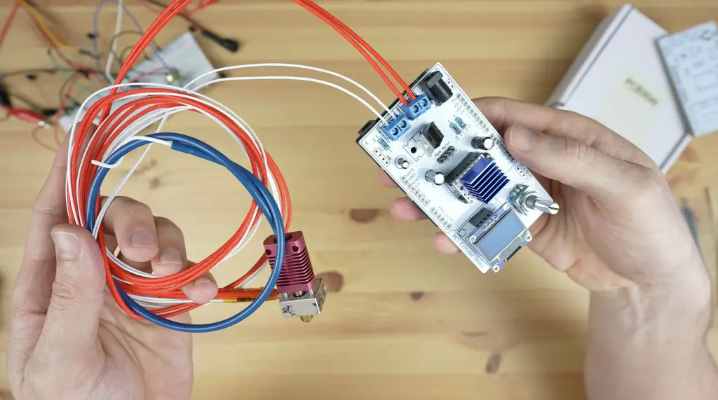
We can then screw our element and thermistor into the terminals, plug in the stepper motor and then close it up with some M3 x 8mm button head screws.
A 3D-printed knob gets pushed onto the rotary push button and we can mount it onto the base.
With all the components in place, we can install the second set of legs to close off the ends of the extrusions.
Second Attempt At The Hot End
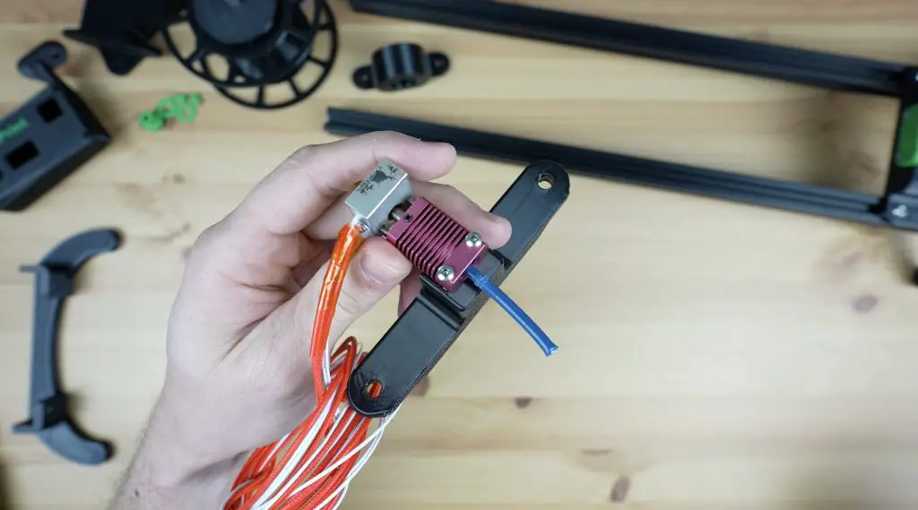
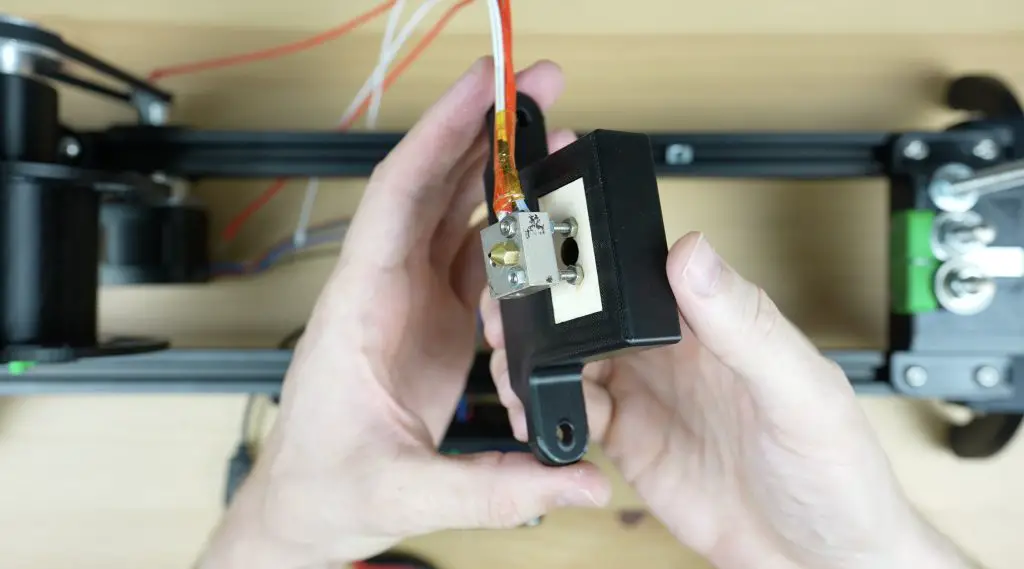
Now that we’ve got the other parts working, let’s go back to the hot end. As mentioned earlier, the device makes filament by softening the strip and rolling it over in the hot end to form a cylinder. This means that the strip needs to start being heated right from the time it enters the hot end or it’ll be very difficult to pull through. So, I redesigned the hot end holder so that the strip passes through the holder and directly into the heat block without any restrictions from the heat break.
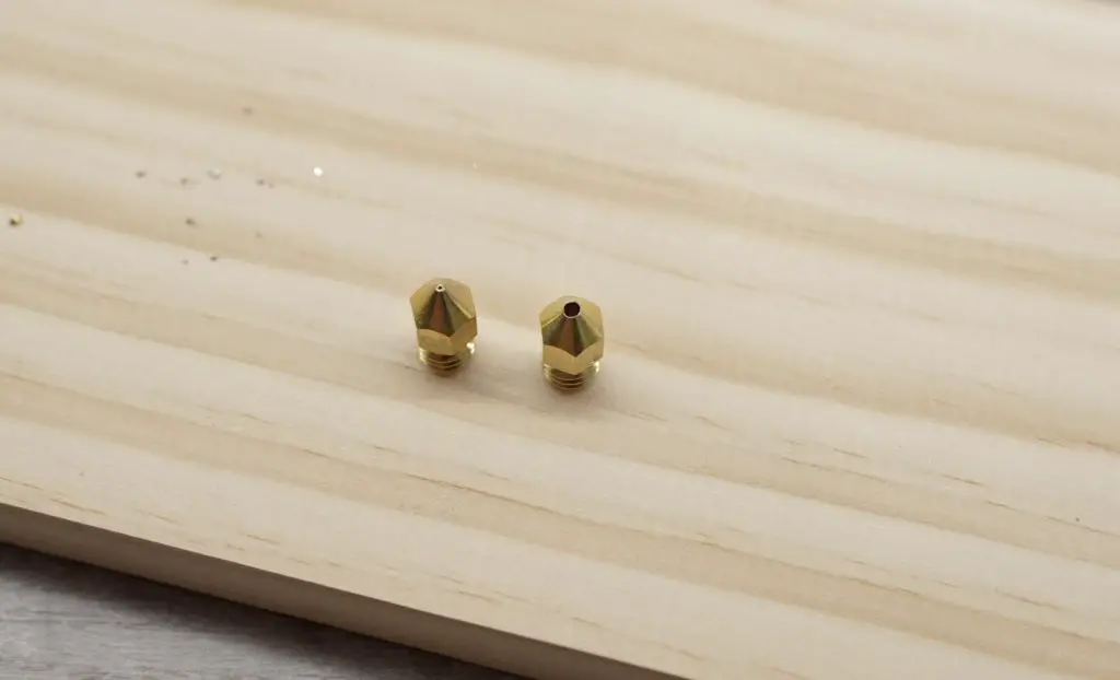
The nozzle is a standard 0.4mm nozzle, so we need to first drill that out to the filament diameter. We’re aiming for 1.75mm but the filament expands a little after it leaves the hot end, so we’ll drill it out using a 1/16″ drill bit, which is just under 1.6mm.
The back of the heat block has a small tapped hole for the heat break. We’re going to open this up with a tapered drill bit so that it is slightly larger than the strip width. The taper will then help to gently fold the edges over until we reach the nozzle diameter.
We can then mount the heat block onto the holder. I’ve used some M3 x 40mm button head screws through the heat block and then nuts to hold it onto the plywood plates on each side of the 3D-printed holder. The plywood plates act as the heat break in this design and stop the screws from melting the plastic holder.
We can then re-attach the terminals and we’re ready to try it out.
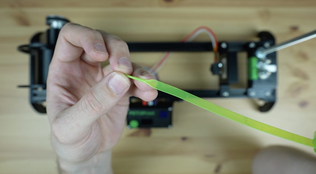
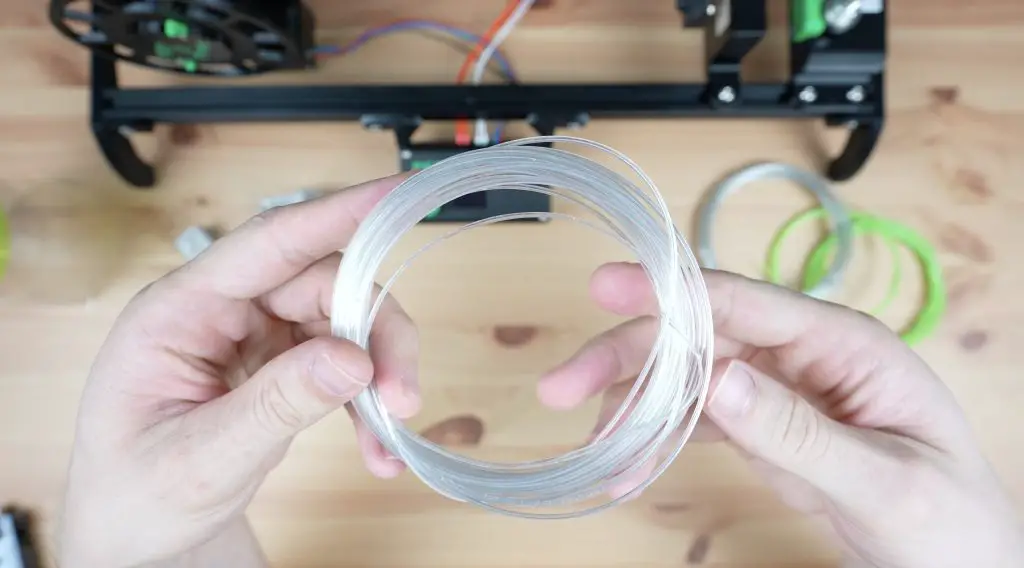
Turning A PET Bottle Into Filament
To run the PET bottle recycler, we first select the target hot end temperature. I’ve found that 215°C to 220°C work well with my bottles. We can then select the motor speed, for which I use 22 to 25. These are just arbitrary units, they don’t relate to rpm or rotational speed. We can then turn the motor on or off, forward or in reverse, with the last menu item.
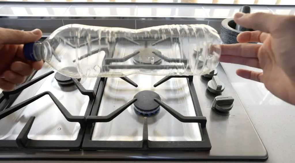
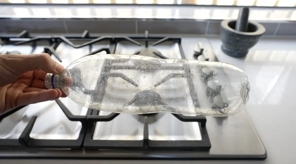
Now we just need a PET bottle to turn into filament. To prepare a bottle, we first need to wash it out and then remove the label and residue as well as any date markings. I found that acetone works well for this. If you don’t remove the label residue, it’ll clog up the hot end and/or cause your printed layers to delaminate.
The bottle cutter works best with a smooth surface and most bottles are rippled in some way. You can smooth them out over some heat, like a stovetop, with a drop or two of water inside the bottle to pressurise it slightly. Be very careful when working with and opening the bottle as the hot air or steam can cause burns – it is best to use gloves.
We can then cut off the end of the bottle, cut a starter strip and feed it into the cutter.
We’ll need some needle nose pliers to pull the end of the strip through the hot end, which has now preheated to 220°C, and then onto the reel.
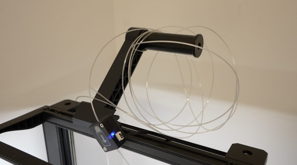
The reel has a small hole on one spoke which we can feed the end through to tie it off. You might need to keep a finger on the knot until there is tension on the filament to lock it into place.
Finally, we can turn on the reeler motor to continue pulling the filament through the hot end and onto the reel.
Now we just wait for it to turn the PET bottle into filament. You can also cut the bottle beforehand to reduce the load on the motor, you’ll then just feed the strip directly through to the hot end without the bearing cutter in place.
Test Prints With PET Bottle Filament
Once the bottle has been converted into filament, we can transfer it from the reel over to the 3D printer to try a print.
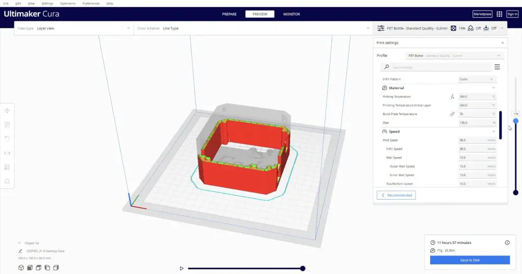
I started out by printing a benchy and calibration cube to see how they turn out. There is a bit of adjusting to do on the first few prints as the PET filament is not quite a solid 1.75mm section, it is hollow in the middle. I found that increasing the flow rate to about 135% gets good results. I printed with a bed temperature of 70°C and a hot end temperature of 260°C.
Once I had the settings right, I was actually pleasantly surprised by how well this filament prints. The calibration cube came out looking really good.
The benchy showed a few signs of stringing and a little under-extrusion in places but is also really good for homemade filament. It’s obviously not as consistent as factory-produced filament but it’s usable for home projects.
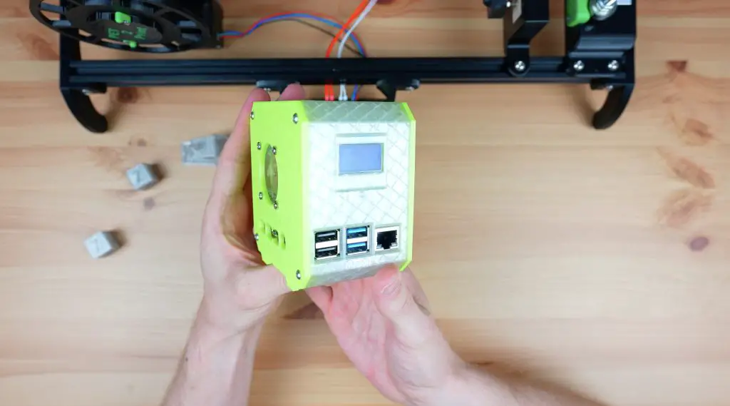
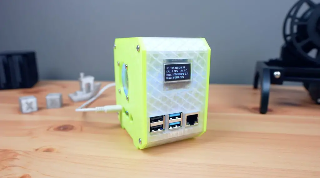
3D Printing A PET Case For My Raspberry Pi
Once I was getting consistent printing results, I converted a few more bottles so that I could print a case for my Raspberry Pi.
This highlights one of the drawbacks of this process. You get about 6-7m of filament from a 1-litre bottle, but with the hollow centre and having to increase the flow rate to compensate for this, it gets used up quite a lot faster than the standard solid 1.75mm filament. It’s also messy to store on the filament holder as it doesn’t like being coiled up.
To print my standard Pi case with no supports, I need 25m of PET filament and this is with a really low infill density and only 2 walls. So I need to swap a new roll of filament onto the printer 5 times for a relatively small print. This is manageable if your printer has a filament runout sensor but it’s still a bit of a nuisance.
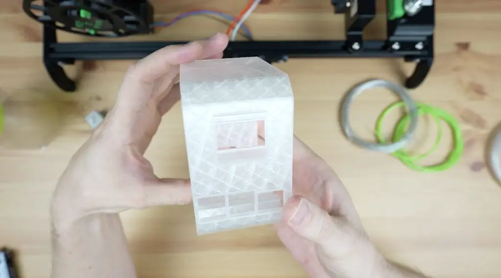
The case body also came out surprisingly well with just a little stringing and again some under-extruded areas. With the partially transparent walls and infill visible, it’s not obvious.
I even used the coloured Mountain Dew bottle for the printed side panels as well.
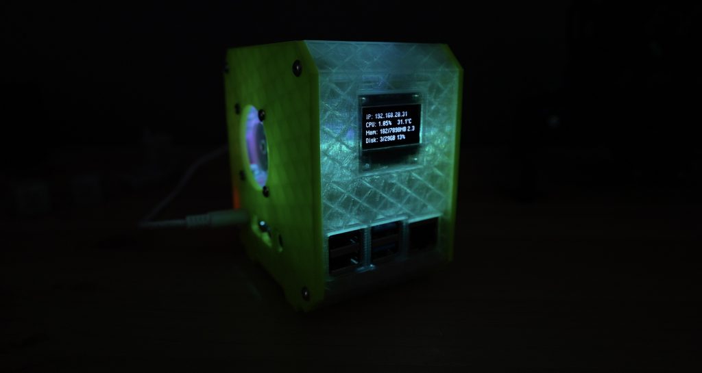
What do you think of the completed case? It’s really cool to think that this was once 5 Coke bottles and 2 Mountain Dew bottles. It also looks great in the dark as the RGB fan illuminates the body of the case.
Final Thoughts On The PET2Print
Overall I’m really happy with how my PET2Print recycler has come out. There are a couple of improvements I’d like to make to it, like getting the displayed temperature to be able to be updated while the motor is running, and perhaps designing a spool mount for precut bottle strips instead of the bottle cutter. It would also be helpful to be able to splice two lengths of PET filament together to avoid having to change the filament during a print but to date, it doesn’t look like anyone has found a reliable process for this.
Let me know what other suggestions you have to improve upon it in the comments section below. As mentioned earlier, I’ve put the code up on GitHub if you’d like to have a go at improving it – I’m sure there is a lot of room for improvement.
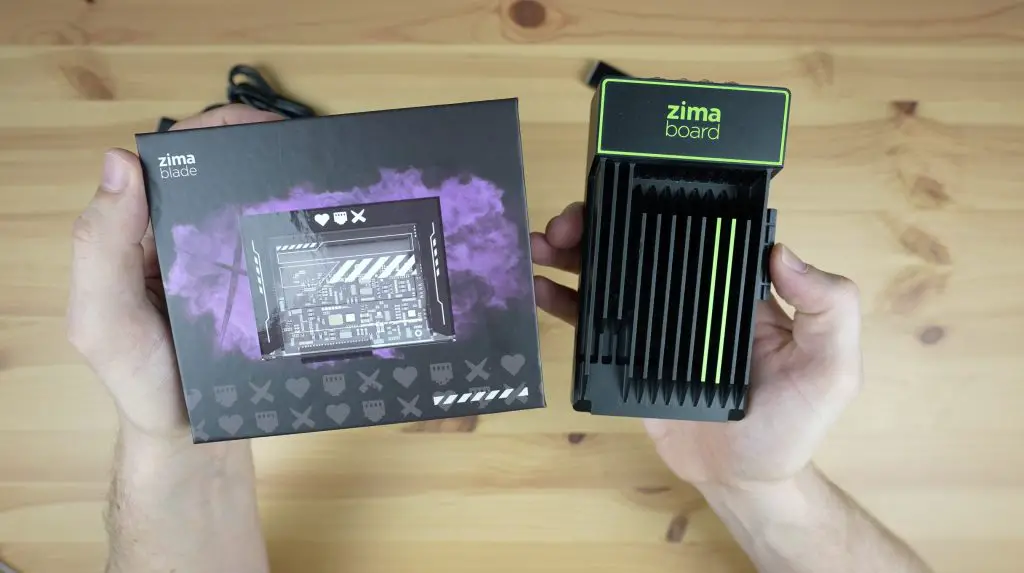
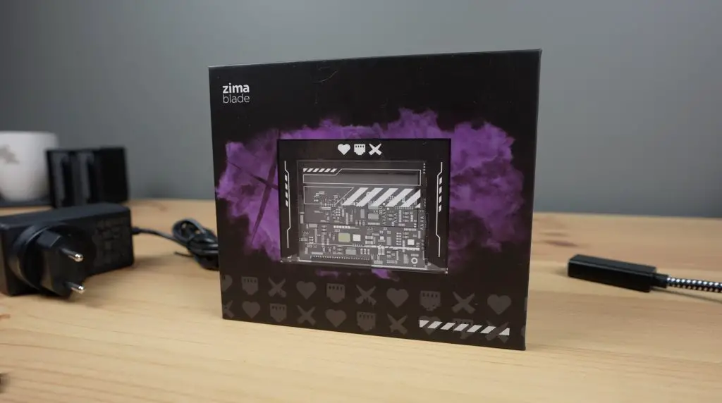
Today we’re taking a look at the new ZimaBlade from a company called Ice Whale.
If you’ve been following my projects for a while then you may recall that I tested their original product the Zimaboard about a year ago. Well this is a new generation that aims to appeal to a broader audience because it is significantly cheaper, smaller and easier to use.
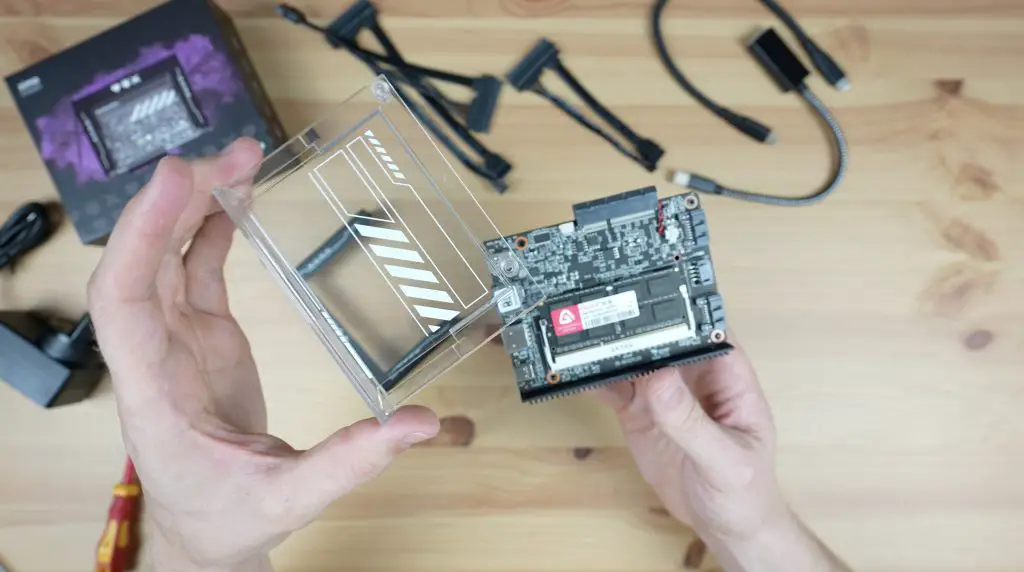
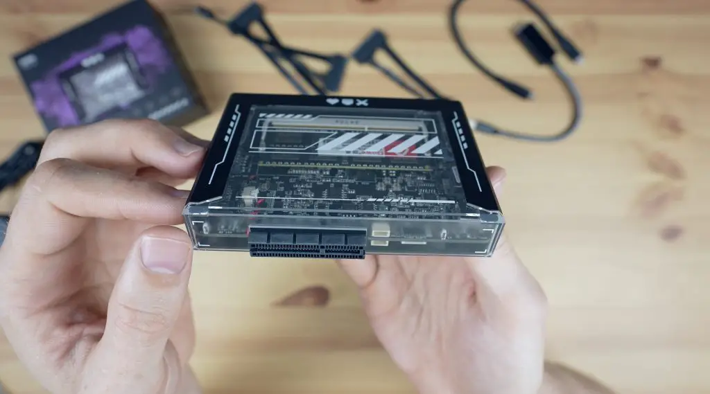
The ZimaBlade has been designed to be a powerful, compact and energy-efficient personal server, with an x86 architecture and a host of IO. This time, they’ve packed the board into a stylish Cyberpunk style case with a clear window into the internals.
It is currently being funded on CrowdSupply, with their campaign set to complete in mid-October. They’ll then get straight into their first mass production run, with plans to start shipping completed units to backers in January 2024.
Here’s my video review of the ZimaBlade, read on for the written review;
Where To Get The ZimaBlade
The ZimaBlade is currently being funded through CrowdSupply, take a look at their campaign below;
Like the ZimaBoard, the ZimaBlade comes in two processor options, a slower Celeron 3760 dual-core model and a faster Celeron 7700 quad-core model.
They are selling the ZimaBlade on CrowdSupply as part of a number of different kits, with the base kit dual-core model at $64 and the quad-core model at $96. So both are less than half of the price of the original ZimaBoard.
They then also offer an Advanced Kit for $128, which adds a power supply, display port adaptor and 16GB of DDR3 RAM to the standard quad-core kit. They’ve got a NAS kit for $144, which is the Advanced Kit with a dual 3.5” storage drive stand and a SATA Y Cable. To complete the line-up, they have a Cluster Kit for $392 which is essentially three Advanced Kits but also includes a storage drive stand and some Y Cables.
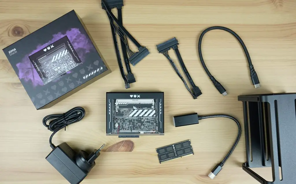
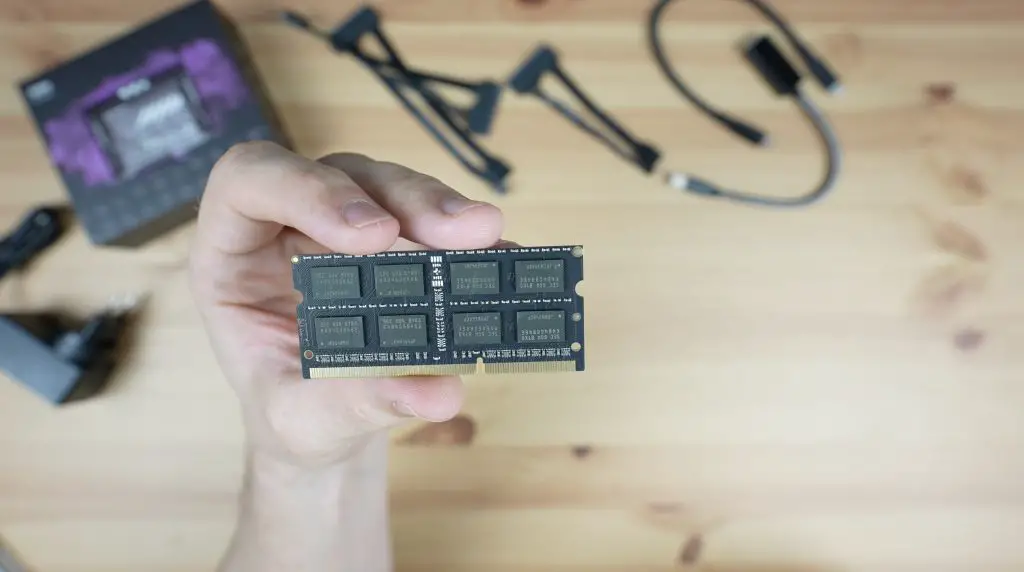
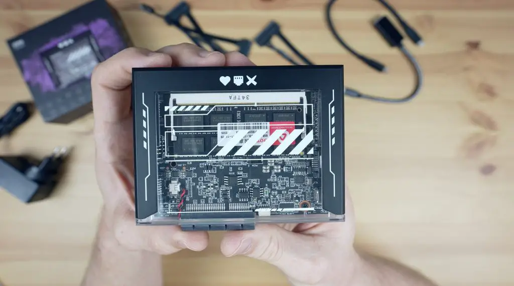
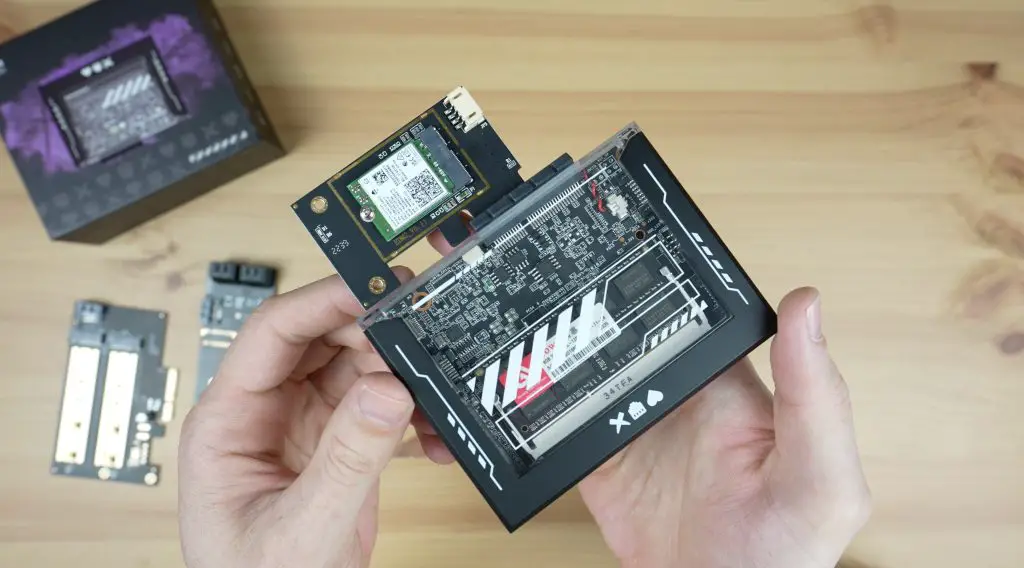
RAM is in the form of a SODIMM slot which is expandable up to 16GB. I like that it’s got the flexibility to customise and upgrade this as you need.
There is also 32GB of integrated eMMC storage.
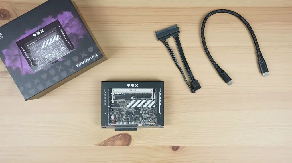
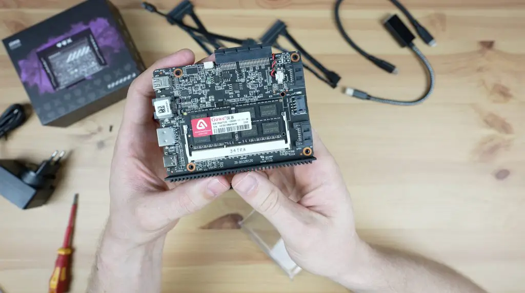
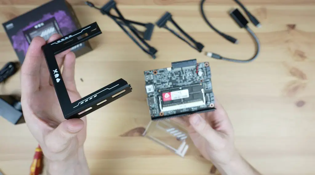
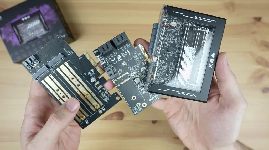
The included case consists of three main parts. An injection moulded black frame, a transparent window and an aluminium base plate that doubles up as the passive heat sink for the CPU.
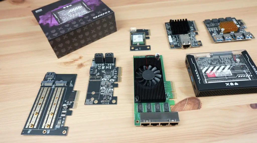
Ports & Interfaces On The ZimaBlade
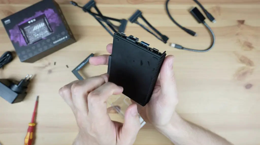
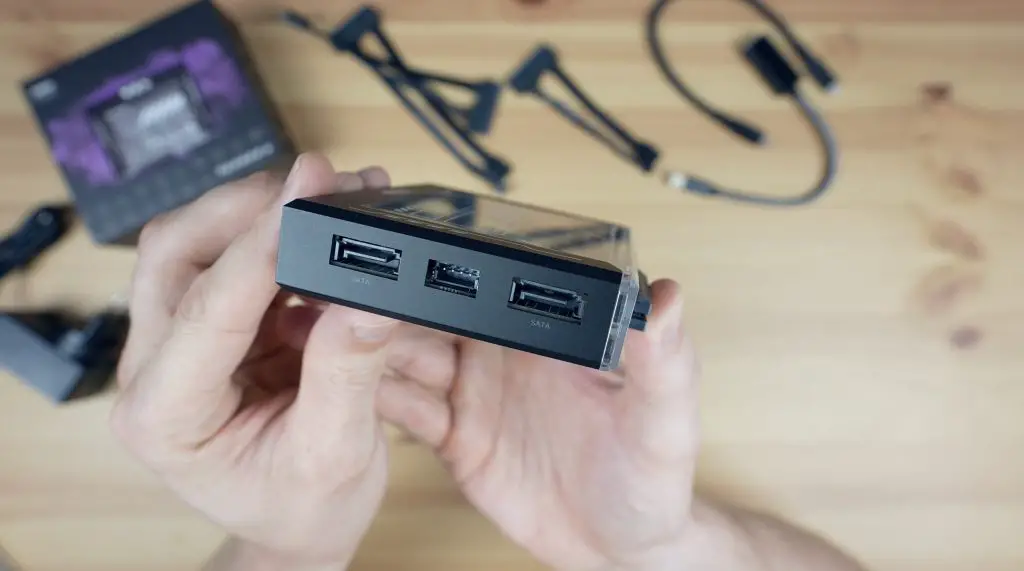
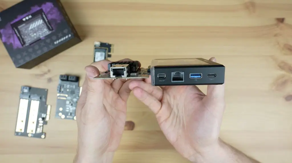
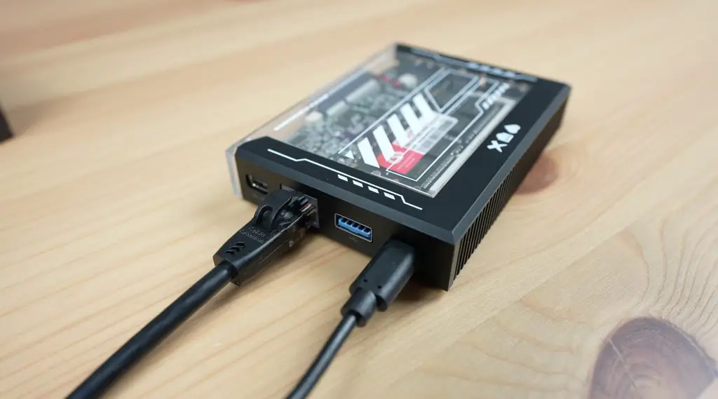
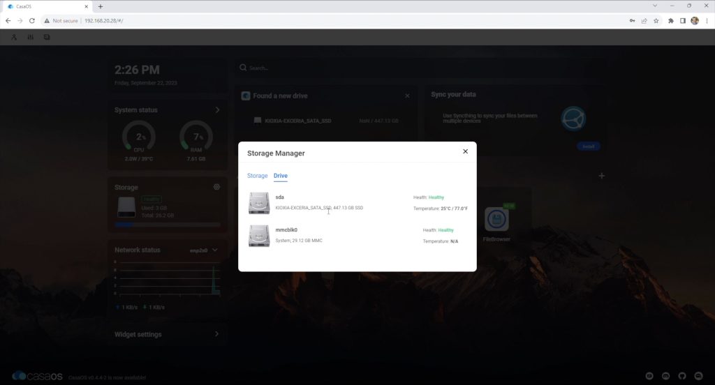
Taking a look around the board. Like with the ZimaBoard, we have dual SATA 3.0 ports on one side, which will each do 6Gbps, and they’ve got a shared power supply to the drives in the middle.
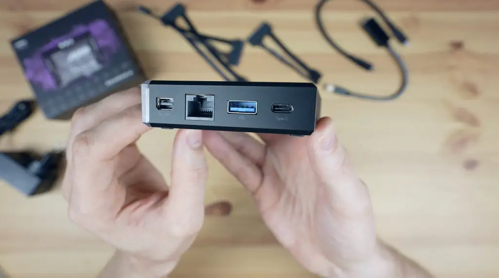
On the opposite side, we have a miniDisplay port which supports 4K at 60hz, a Gigabit Ethernet port, a USB 3.0 port and then a USB C port which can be used for data, power or for another display.
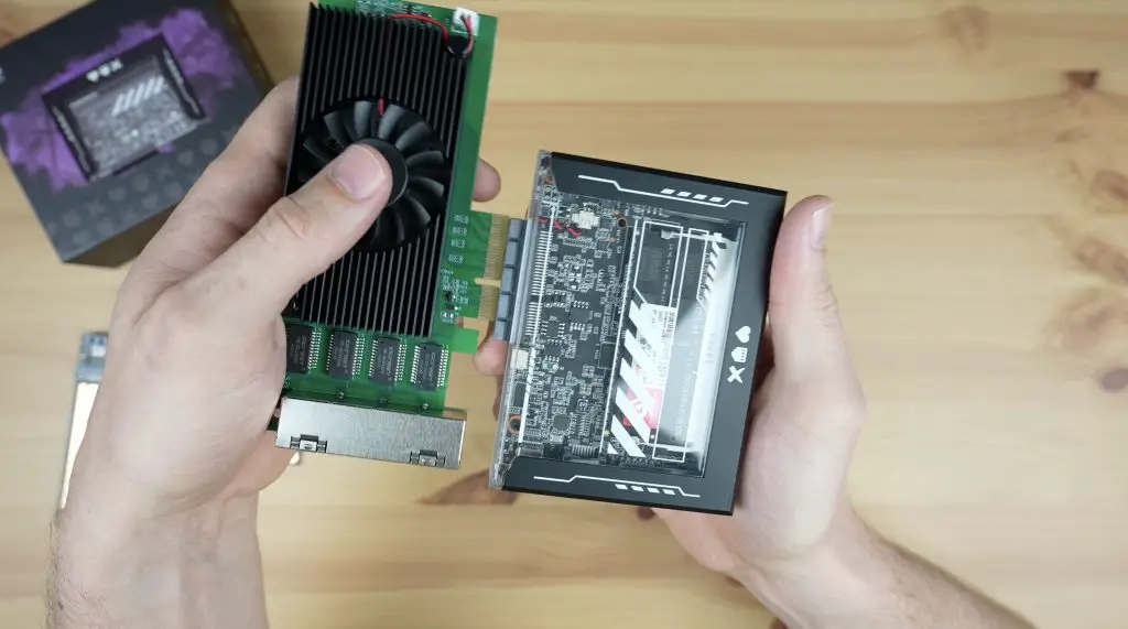
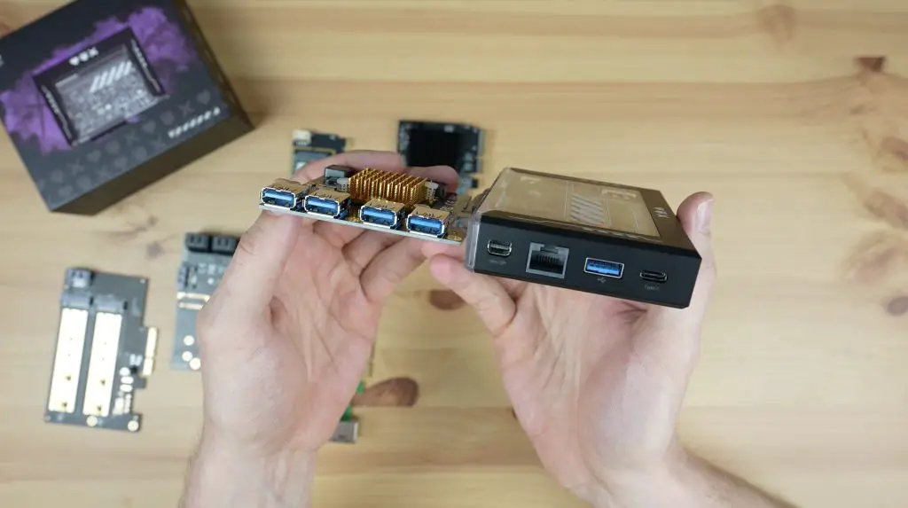
Along the main side is one of my favourite features, a 4-lane PCIe 2.0 port which will do up to 2 Gb/s.
This port allows you to really customise the ZimaBlade to suit your particular application. You could add a SATA or M.2 NVME adaptor to add storage to your ZimaBlade.
Or improve its networking abilities with a WiFi 6E adaptor, or a 2.5G or even a 10G Ethernet adaptor.
Or add additional USB ports if you need.
So that’s an overview of the hardware, next let’s get it booted up and take a look at the software.
First Boot & Operating System
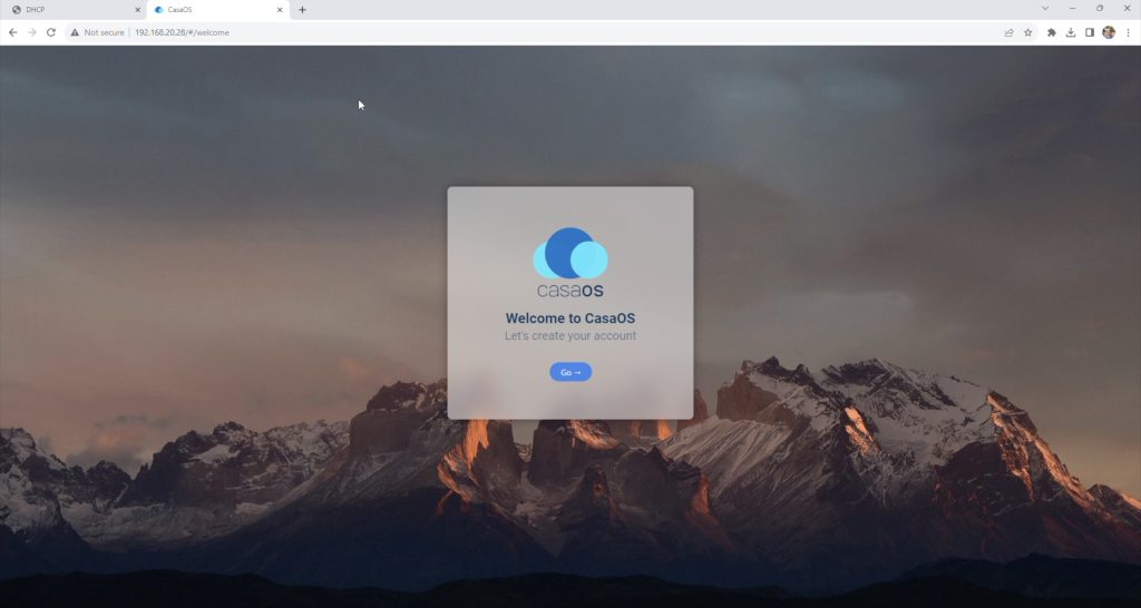
The ZimaBlade, being x86 can run an extensive range of operating systems, but it comes preloaded with Ice Whale’s Debian-based software package called CasaOS.
This is essentially a Docker installation with an easy-to-use web interface, so it’s really easy to start deploying Docker images with very little configuration required.
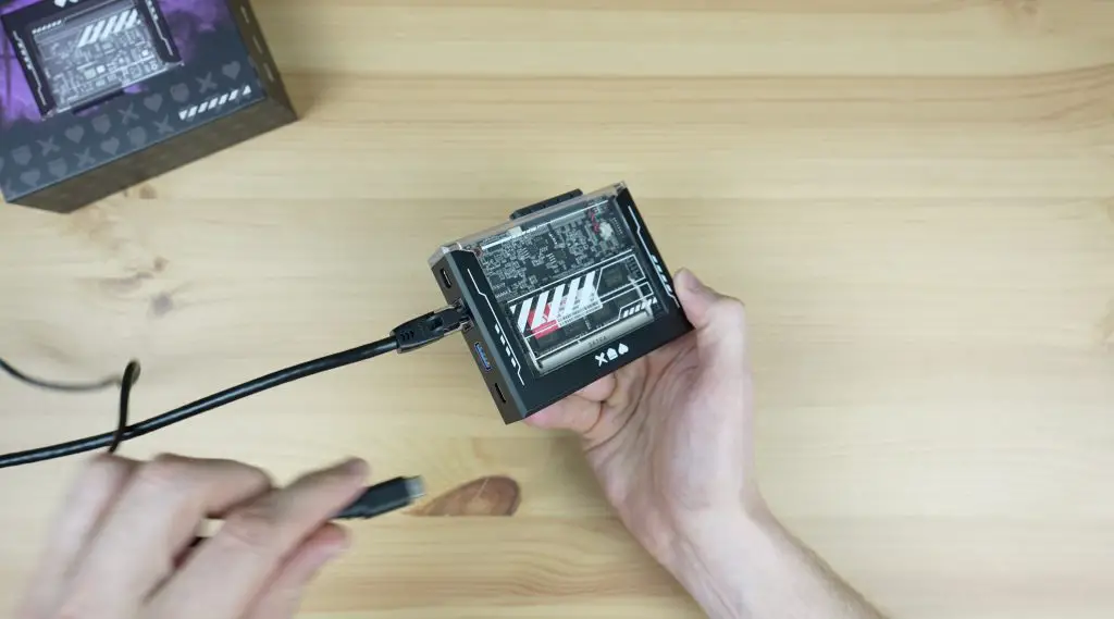
With CasaOS installed by default, it is designed to run headless (without a monitor), so we can boot it up and then access it through a web dashboard on another computer. To do this we just need a network cable and the included power adaptor.
There is a tiny red power LED on the underside of the board but it is quite difficult to see through the case and the network port doesn’t have any activity LEDs on it. So it is a bit difficult to see whether the ZimaBlade is powered up.
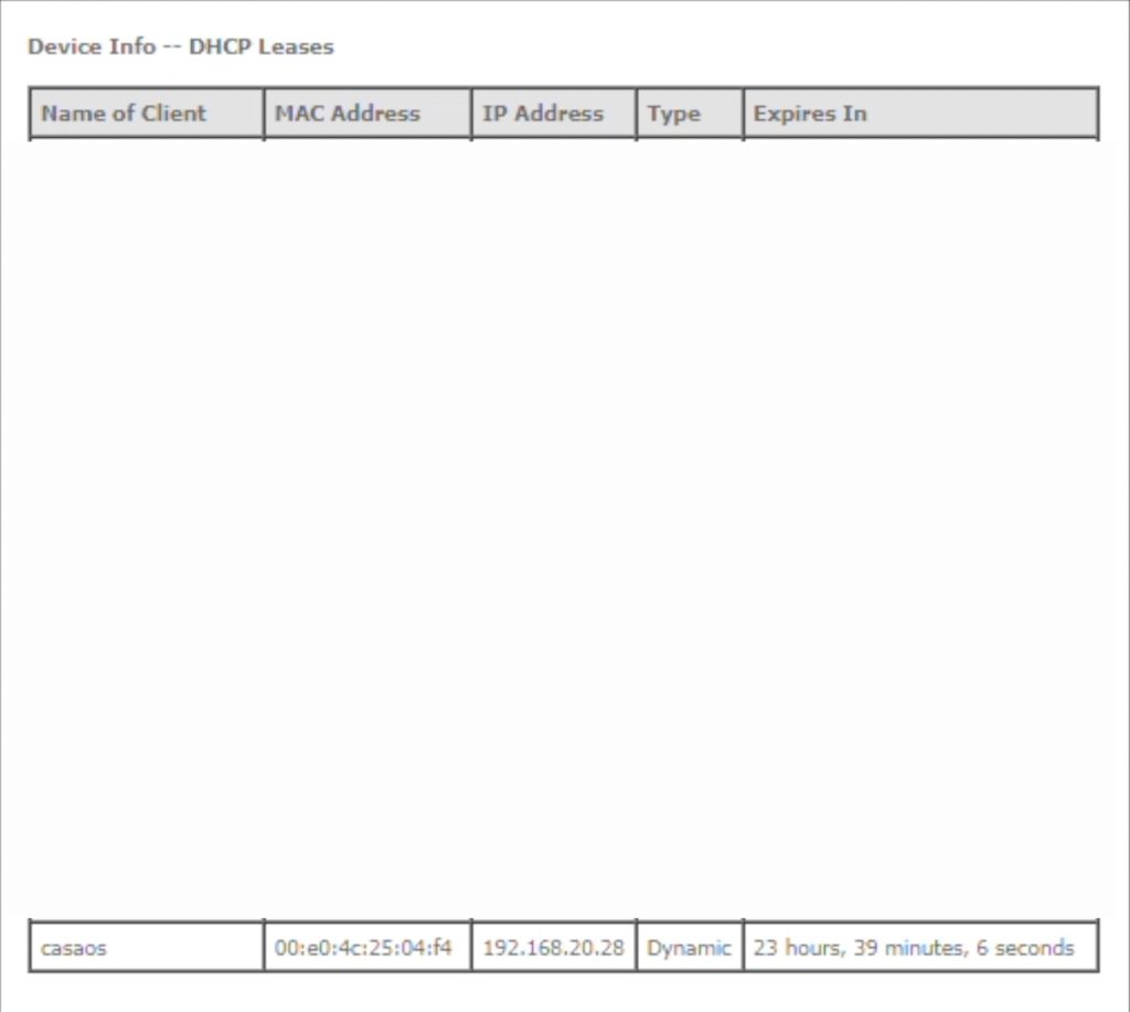
We’ll give it a couple of minutes to boot up and we then need to find it’s IP address on our network so that we can access the web dashboard.
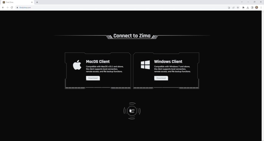
They have created an online tool called Find Zima which searches your local network to find connected Zimaboards or Zimablades. This doesn’t yet work on this early version of the ZimaBlade’s firmware but I was able to find the IP address of my ZimaBlade by looking at my network’s DHCP table.
We can then type the IP address into a web browser on a computer on the same network and create a login to CasaOS.
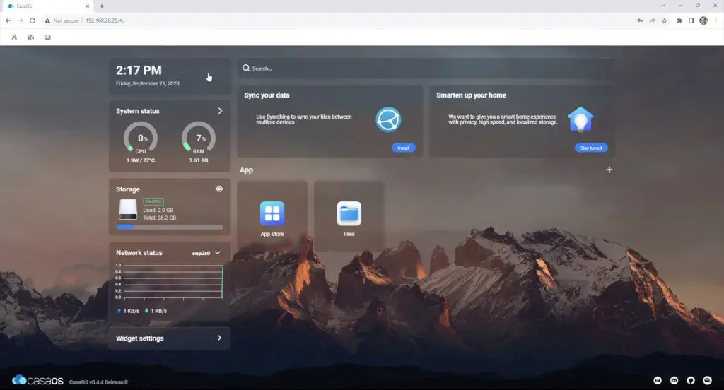
Using CasaOS & Installing Apps
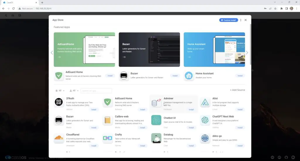
Once we have created a login, we land on the CasaOS homepage. This has a few widgets installed by default which show the date and time, system stats, storage stats and network status in a bar on the left. On the right side, we then have the app area.
They make it really easy for beginners as they have created their own App Store which has a range of a little over 50 ready-to-run docker images that have been pre-configured to run on the ZimaBlade.
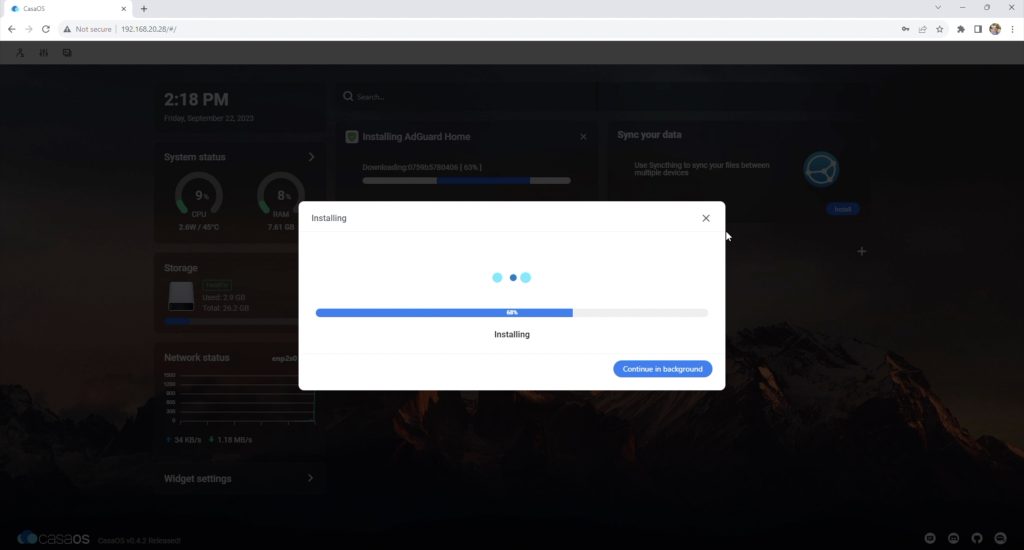
To start with, let’s go with setting up AdGuard Home first as a network-wide ad and tracker blocking service.
It’s a one-click install and we can then access the AdGuard homepage by simply clicking on the App. You’ll still need to reconfigure your network’s DNS settings to get traffic flowing through it but it doesn’t get much simpler than this to get applications running.
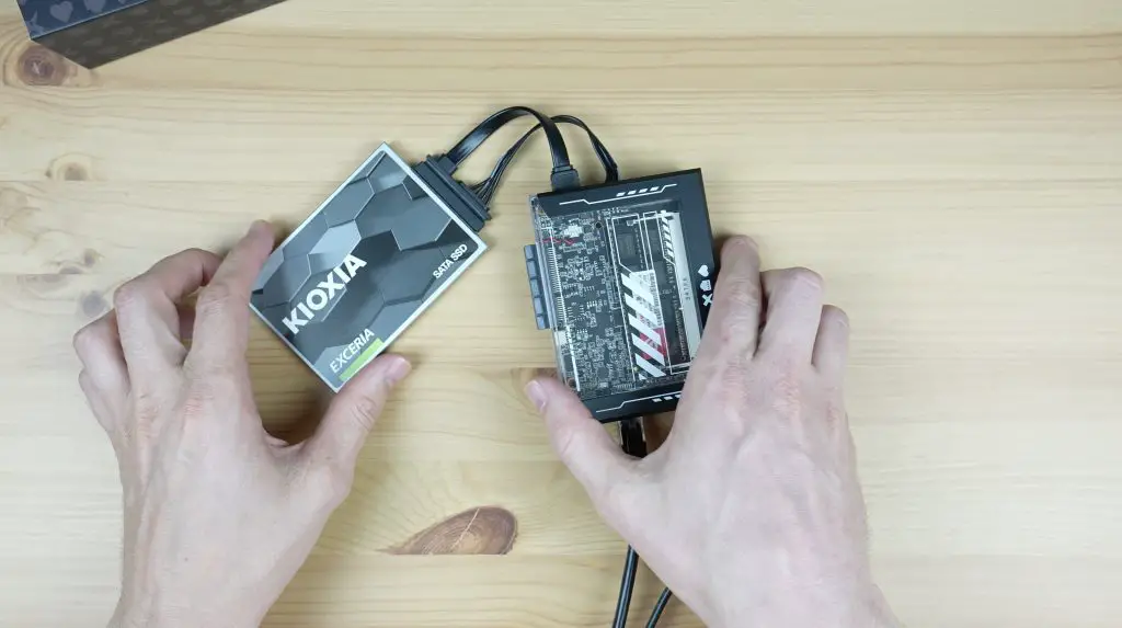
There are loads of options for Apps to run on the ZimaBlade to truly customise your home server experience. You could build your own local networked file storage system or NAS after connecting some storage drives to the SATA ports.
Like I did with the ZimaBoard, using Plex, you can build your own media server to host your own media and avoid having to pay for subscription services.
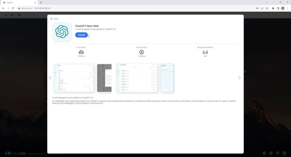
There are also a number of other apps available. For example, we can install a ChatGPT app.
If this operating system is not for you, you are not locked into CasaOS. You can overwrite the operating system with your own OS install, and being x86 architecture, you’ve got a lot of options.
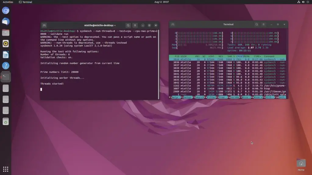
Running A Sysbench Benchmark
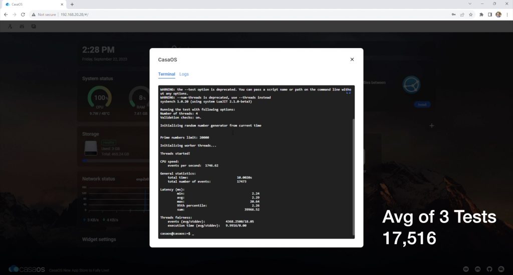
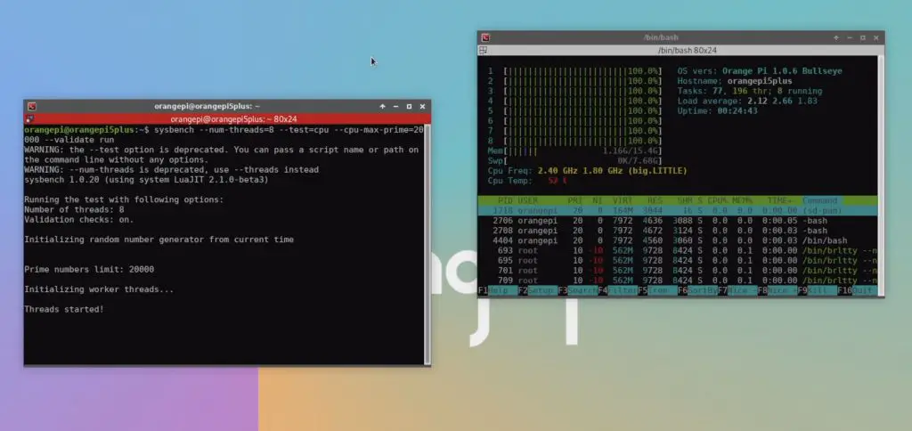
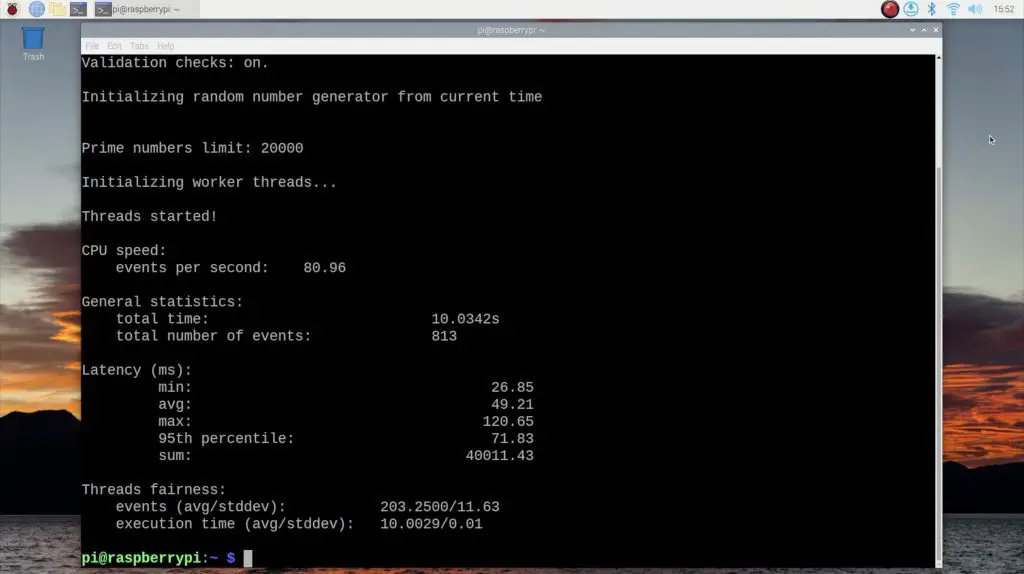
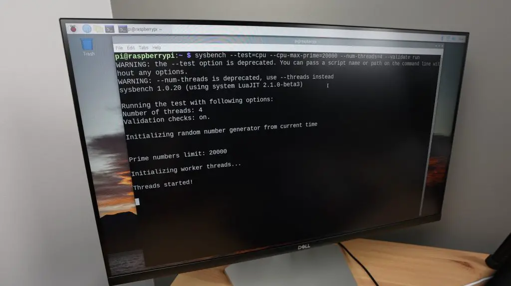
Performance-wise, we can test the ZimaBlade’s performance by running the Sysbench benchmark.
After three consecutive tests, I got an average score of 17,516.
So it is quite a lot more powerful than a Raspberry Pi 4, which would score around 2,000 but is not as powerful as a board running the 8-core Rockchip RK3588 processor which would score around 50,000.
Power Consumption
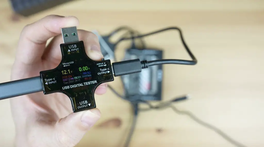
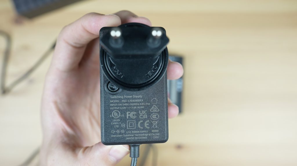
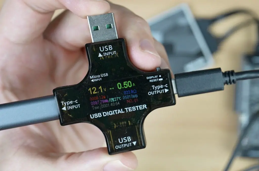
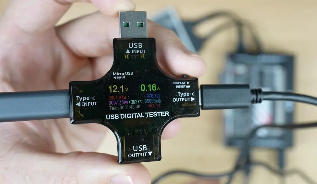
Lastly, let’s take a look at its power consumption. When I started this test, I found something a bit disappointing with the power adaptor. It is a USB-C style adaptor, but when you plug it into the power meter, you immediately get 12V out of it, even without a connected device.
Without a connected device, the adaptor should be outputting 5V and it should only step this up when the connected device agrees on a higher voltage. I checked the adaptor and it also only had it’s 12V output identified.
While this is fine for this particular application, having adaptors like this in existence around your home puts all of your other electronics at risk. You could very easily plug in a non Power Delivery, or lower voltage Power Delivery device like a smartphone and instantly destroy it’s power circuit. I really don’t like that these non-compliant adaptors are being made and I hope Ice Whale fix this in the final version of the product.
When idle, the ZimaBlade uses just under 2W, which is impressively low.
When fully loaded this jumps up to around 6W. So even running fully loaded, this board uses less power than a small LED lightbulb.
Final Thoughts On The ZimaBlade
That’s my first look at the ZimaBlade. I quite liked the original ZimaBoard, especially the simplicity of the software and the inclusion of the PCIE port, so having the same features available in a much cheaper package is great.
I really like that the ZimaBlade includes a case, so you don’t have to worry about spending more money to protect it. It would be nice to see them do something to better accommodate PCIe cards that are plugged into it as well, these currently look like afterthoughts when used with the case.
This is also a fantastic home server option for someone who is energy conscious, drawing only 2W most of the time it is on is not even going to be noticeable on your power bill. I’m looking forward to trying out some PCIE expansion cards to add functionality to my ZimaBlade home server in the future.
Let me know what projects you’re keen to try on the ZimaBlade in the comments section below, and let me know if you’ve tried any good apps available in CasaOS.
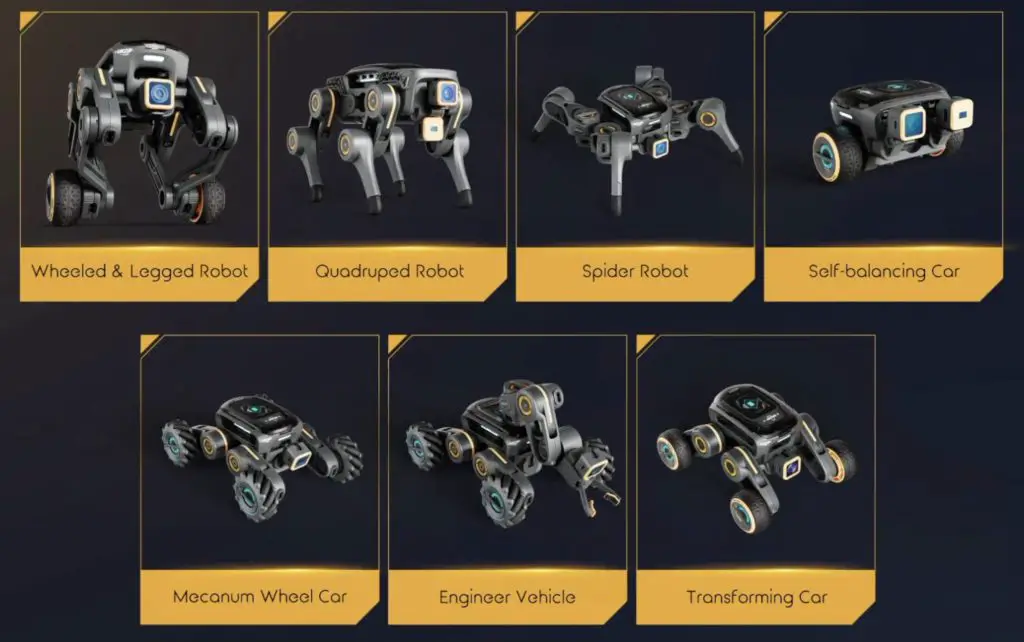
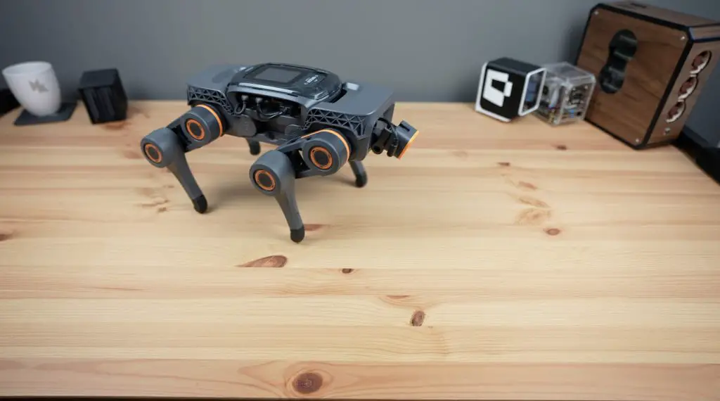
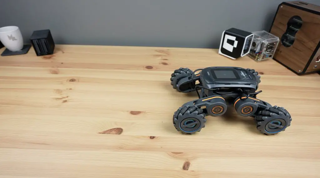
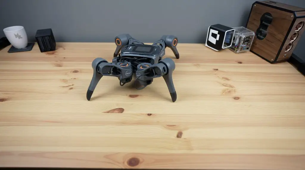
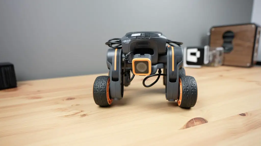
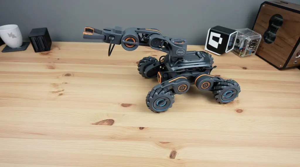
Today we’re taking a look at a new modular robotics kit called UGOT. It’s been developed by a company called UBTECH, who already have quite a few products in the robotics space. They are particularly known for their humanoid robots like the UBTECH Walker and their educational kits, but they also have a number of commercial robots available as well.
The UGOT robotics kit is currently being launched on Kickstarter and I think it’s going to be quite a popular product.
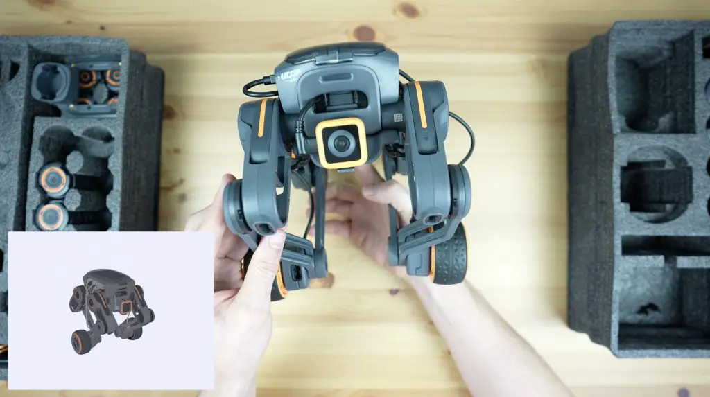
UBTECH have sent me an early version of their UGOT kit. It’s an assortment of motors, joints, sensors and cables that connect to a central controller to build a number of different robots. At this stage, this kit includes the parts to build 7 different robots but from their website, they clearly plan on expanding this to include drone-style robots with a propeller kit and a two-legged walking robot.
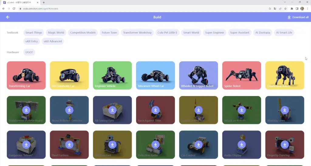
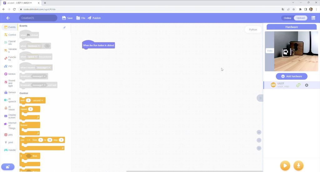
You’re also not just limited to the robots that come with the kit, the entire system is wirelessly programmable through their online platform called uCode and you can drag and drop blocks to add functionality to existing robots or even create your own robots from scratch.
Here’s my video review of the kit, read on for the written review;
Where To Get The UGOT Kit?
The kit is currently being crowd-funded through Kickstarter, so is available through their funding page;
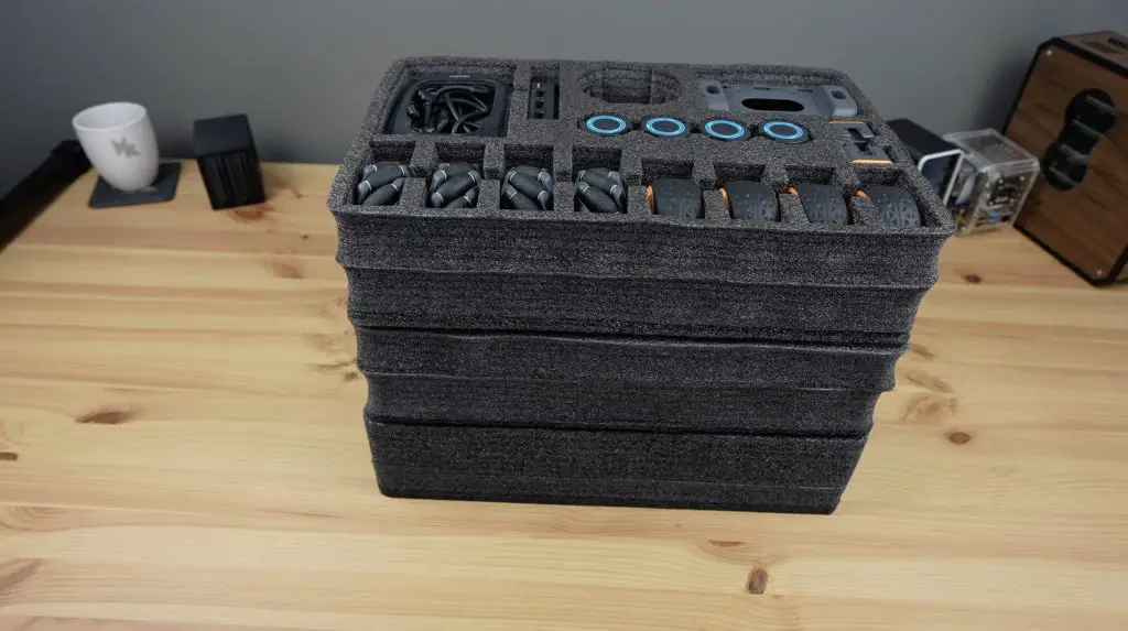
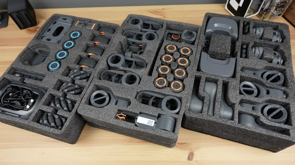
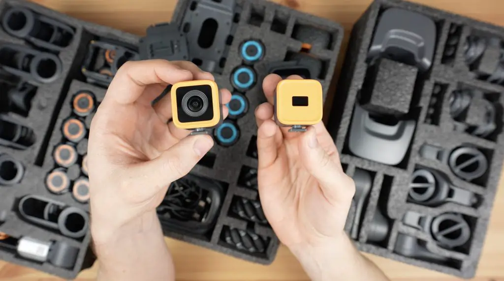
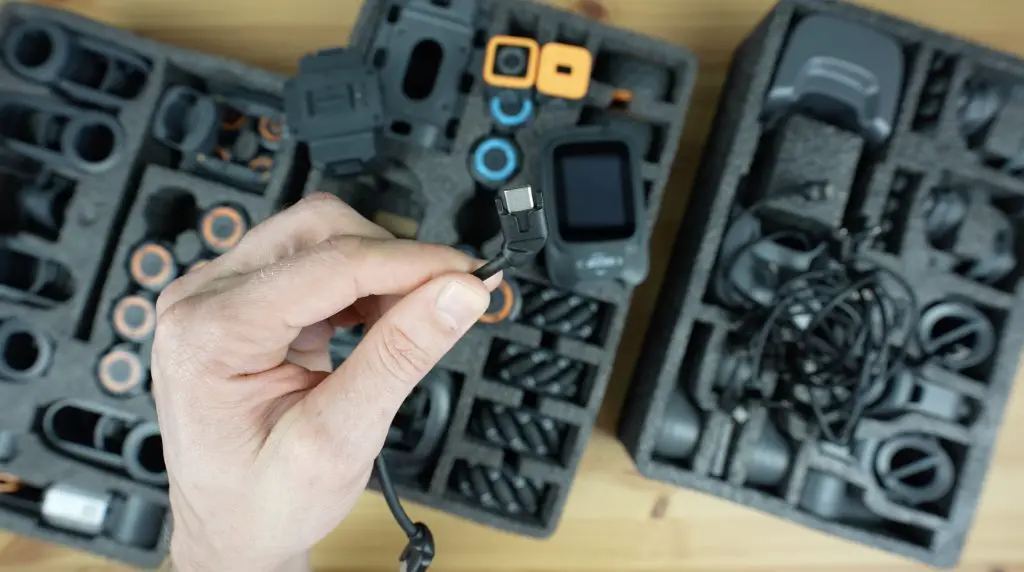
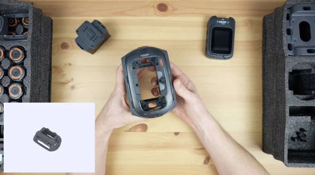
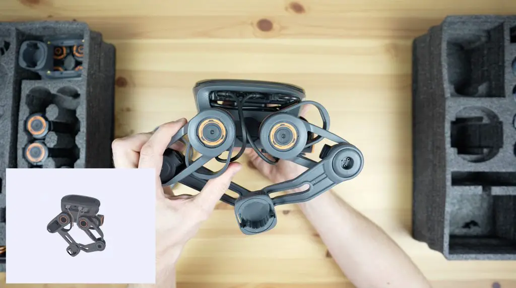
As mentioned above, the kit is an assortment of motors, joints, sensors and cables that connect to a central controller to build a number of different robots. All of the components come individually protected in three foam trays.
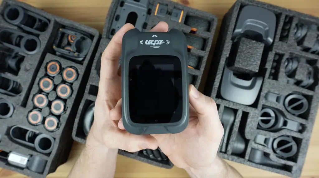
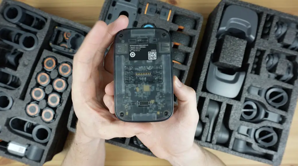
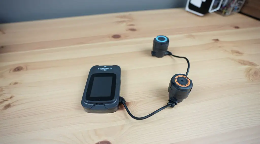
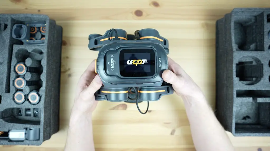
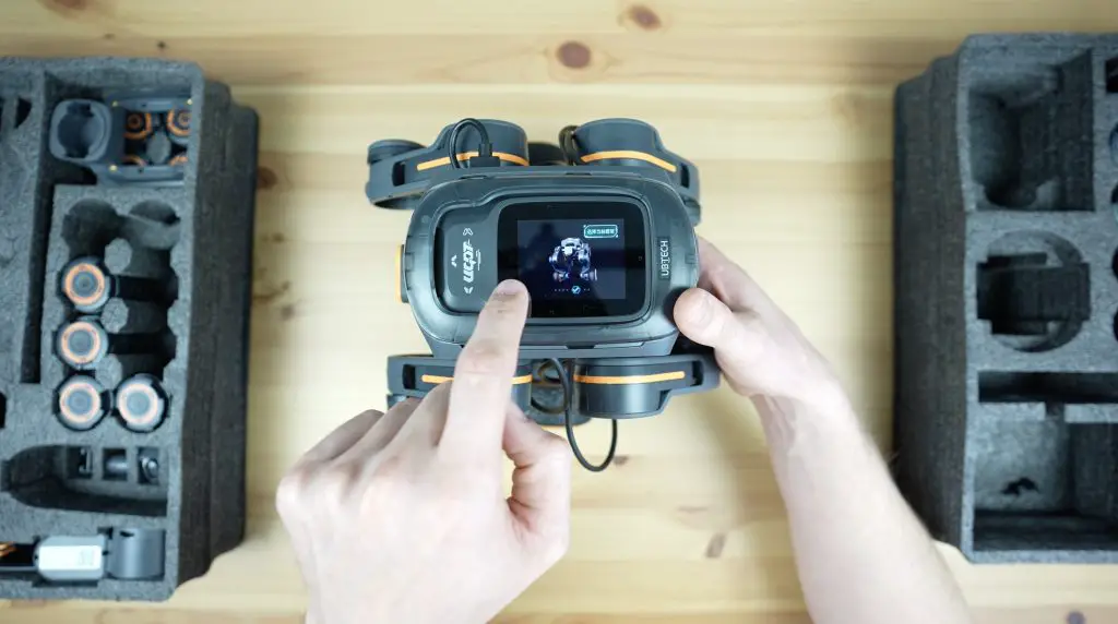
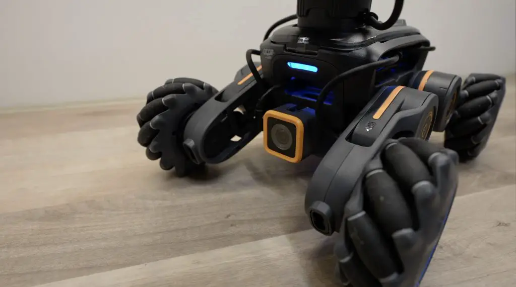
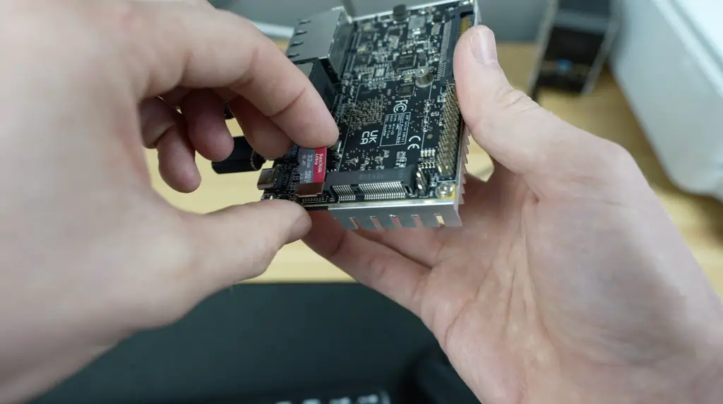
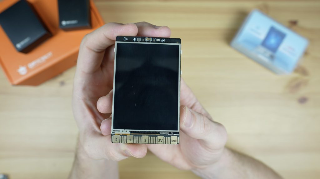
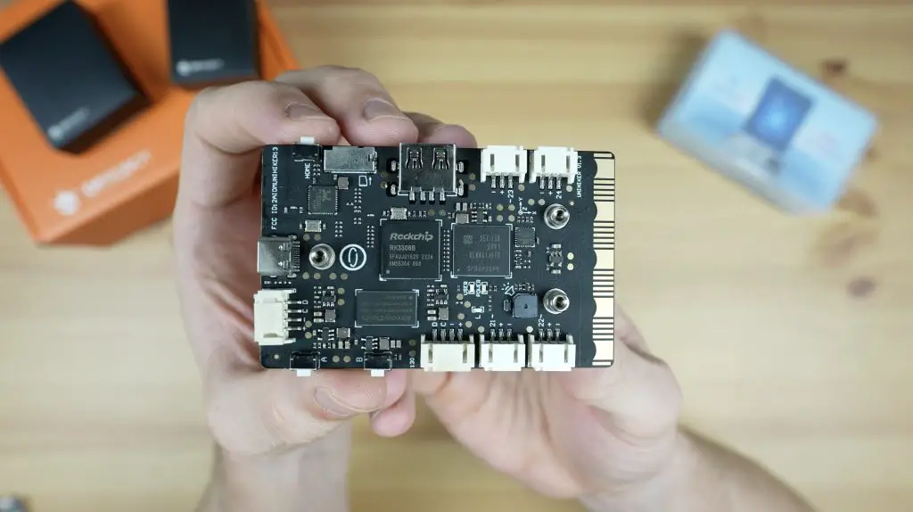
Let’s start by taking a look at the controller or brain of the robot. This is a computer with a range of ports around the edges. It’s got a connector for the battery on the back and a 2.4” LCD touch display on the front.
It’s got a quad-core Arm Cortex-A55 CPU running at 1.8GHz, 4GB of LPDDR4 RAM and 32GB of EMMC storage. That is coupled with an integrated GPU, NPU and motion sensor system which includes a 3-axis accelerometer, 3-axis gyroscope and 3-axis geomagnetic sensor. It’s also got RGB LEDs, a 3 microphone array and a speaker.
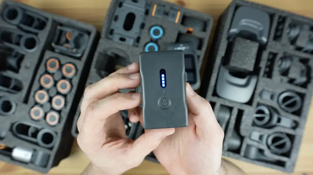
To power the controller, we’ve got a 2600mAh 11.1V lithium-ion battery pack. This gives the system a run time of about 2.5 hours, depending on how many motors are being used.
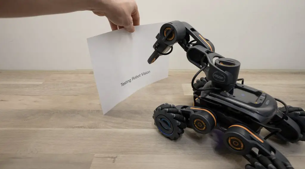
To give the controller a sense of its surroundings, we’ve got an included 720P camera module and a distance sensor. Through software the camera can be used to recognise things like gestures, movements, signs and QR codes, and the distance sensor obviously measures the distance to surrounding objects.
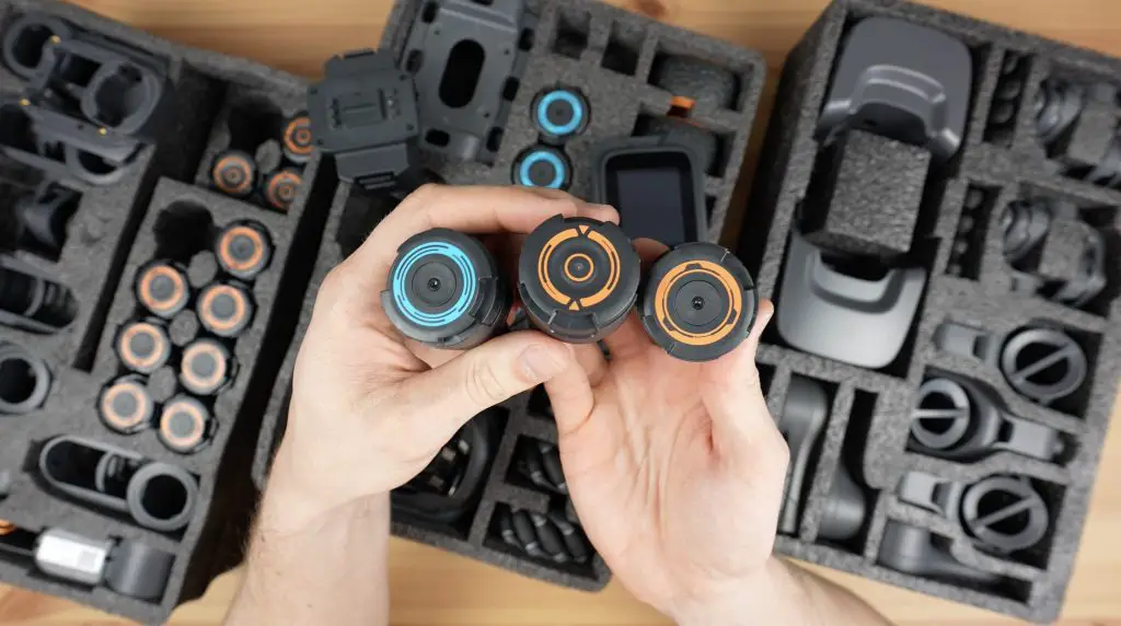
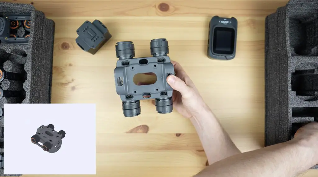
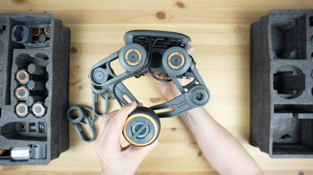
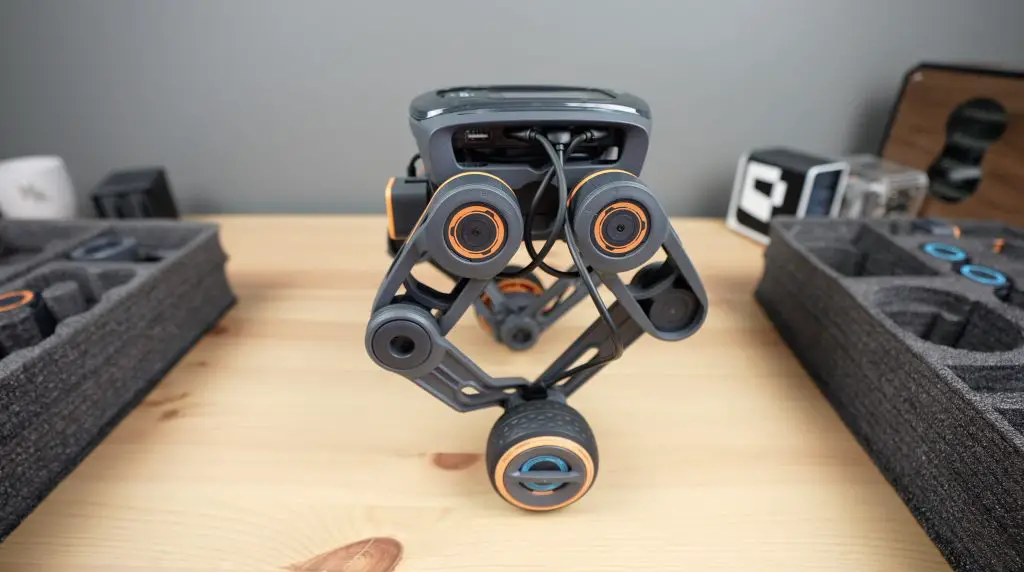
To actuate the wheels and form the joints, we’ve got a few different motors. The blue ones are continuous rotation motors which are used for wheels and the orange ones are servo motors which are used to actuate leg and arm joints. These have higher torque and lower speed than the continuous motors and have position feedback through a magnetic encoder. There is also a set of motor dummy pieces that just act as fixed joints in the place of motors for specific robot configurations.
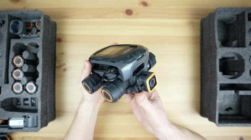
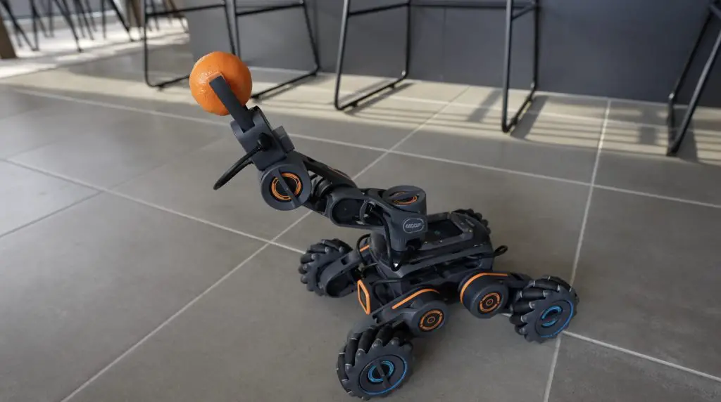
The last included actuator is a grabber for the end of a robot arm.
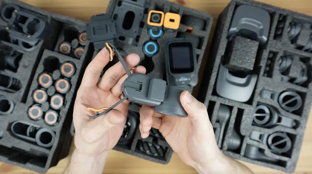
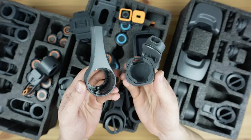
Then we’ve got a number of moulded plastic arms, legs, joints and adaptors which allow you to connect the motors and sensors to the controller to build the actual robots.
These are quite well thought out. They lock into place around the motors to create quite robust builds. You can knock them around a bit and they still hold up well.
Lastly, we’ve got a pack of cables. These look to be USB-C style cables with a shroud around them and they connect the motors to the controller.
The motors have two ports on them and are chainable, so you can pass commands through one motor to another and a few of the standard designs actually use this feature.
Assembly Instructions & Programming UGOT
Now that we’ve seen what is included in the kit, let’s take a look at the software.
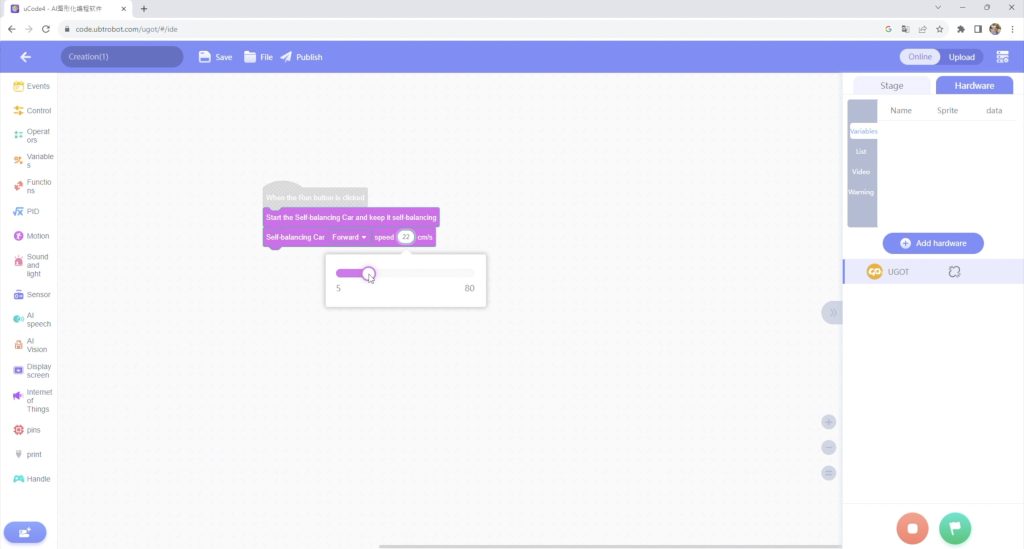
Assembling and programming each robot is done through uCode. This is an online tool that is also shared with their other educational platforms.
It gives you step-by-step instructions to assemble each robot in the form of a 3D model and parts list.
Once the model is complete, it then takes you to a programming interface.
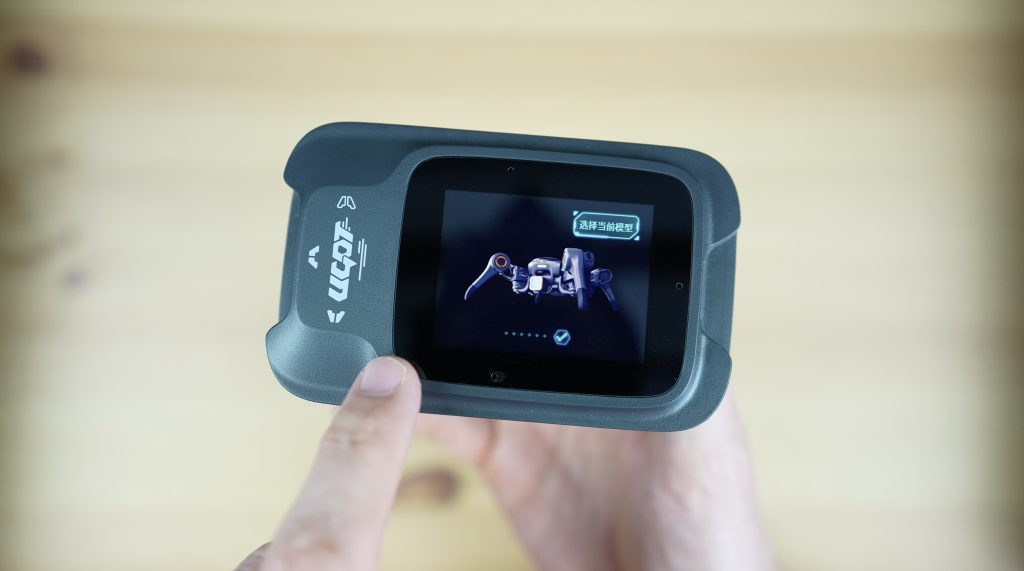
UGOT includes basic programs for each robot preloaded, so you don’t have to do any programming to get started. As a beginner, you can simply build the model you’d like and then run the program directly from the controller.
If you then want to add functionality or change the robot’s behaviour then you’ll do it through block coding or Python in uCode.
I’ve tried building all of the included models and I’ve run the demo program for each of them. I really enjoyed how easily they go together. There is a bit of tinkering to get the first one assembled but once you learn how the joints and cables work, changing between robots is literally a 5 minute exercise.
Assembling A Test Robot
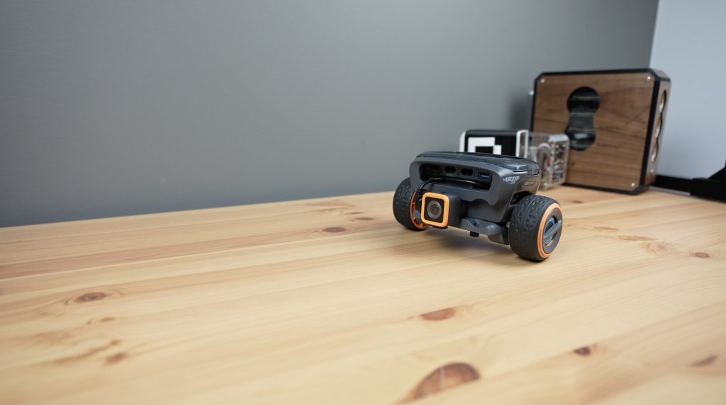
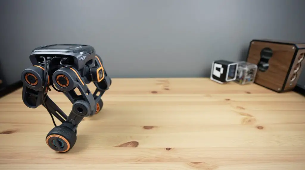
Let’s try to put together the wheel and legged robot and you can then see how the assembly process works.
All of the models start with this main body section, which we’re going to attach four servo motors to as well as a bracket for the front camera. We then add the base plate with some thumb screws to lock it into place.
Next, we add the battery and the controller. This is one thing that I’d like to see them improve upon, it would be great to have this body cage designed in a way that allows the battery to be swapped out without having to remove the controller. You can charge the battery when it is installed but it would allow you to keep working on your robot if you could just swap the battery out easily instead.
Next, we can plug in the cables for the motors.
We then add the leg system to each motor, with a continuous rotation motor on the end for the wheel.
With that complete we can do the same on the other side.
The robot is then complete and we can turn it on.
We select the model that we’ve built and a program to run on it. The included program extends the legs and keeps the robot balancing.
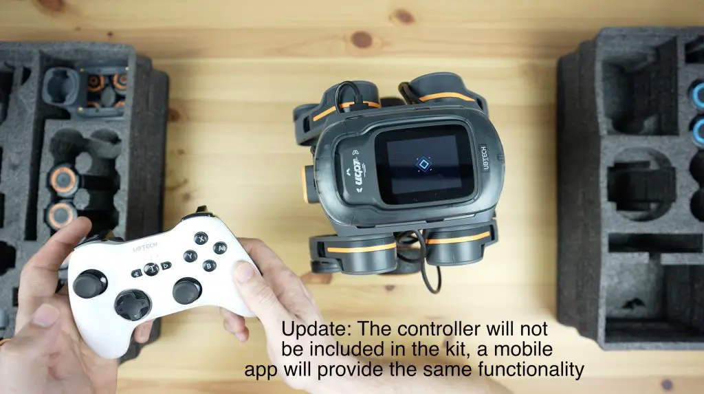
Now we need a way to control it. The sample kit that they sent me also includes a Bluetooth controller which can be used to wirelessly control each of the robot’s movements. UBTECH have advised that the actual kits will not include a controller but the robot will rather be able to be controlled through a mobile app.
So we can use the controller or app to raise or lower the body and to drive forwards, backwards or turn.
Trying Out The Other Included Robots
I have built and tried all of the included robots and found it quite easy to switch between them.
I think my two favourites are the one that I built as an example, called the wheel and legged robot, and the engineer vehicle.
Other UGOT Features
You can also add functionality to each robot using the drag-and-drop block coding platform. There is a really long list of powerful functions which include blocks for the particular robot style and blocks for the sensors.
You can even use the included camera to recognise text, gestures, codes and colours to add features to your robots.
Through uCode you can see a live feed of the camera on the robot and they plan to make this available through their mobile app as well, so you can use it as a FPV camera.
Final Thoughts On The UGOT Platform
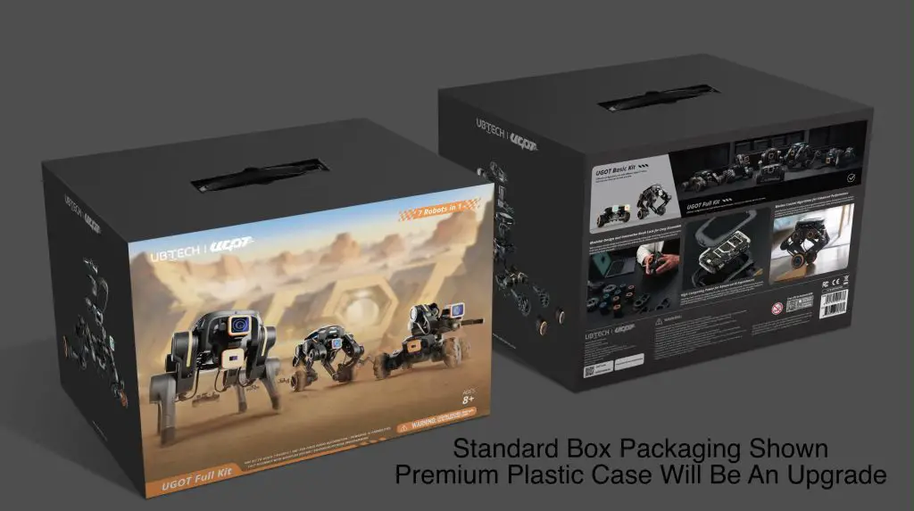
The final version of the kit will come in a neat layered box in two versions, but they will also be offering a hard plastic case that houses the three layered inserts as an upgrade option. So it should be quite a neat all-in-one kit.
This is obviously an early pre-production set so I’d expect that the final product may have some changes or improvements but it looks like it has a lot of potential.
I really like the quality and robustness of the parts. The motors feel solidly built and all of the arms and legs are rigid and lock together well.
Other than the battery not being easy to swap out and a few minor software bugs like the model select button still being in Chinese when in English mode, it’s actually a surprisingly stable system for one that is still in pre-production.
As with the other crowd-funded products that I’ve reviewed, I’d like to finish off with a reminder that crowdfunded projects carry some level of risk and that there is no guarantee that the final product will live up to the promises made in the Kickstarter campaign. UBTECH is an established company with a good history of delivering robotics products and they’ve obviously completed their pre-production run, which has allowed me to demonstrate it. From what I have seen it certainly looks like they have put a lot of time into its development, and the platform is already usable, but that isn’t to say that the product is without risk – it is not yet a fully-fledged retail product.
Let me know what you think of it in the comments section below.
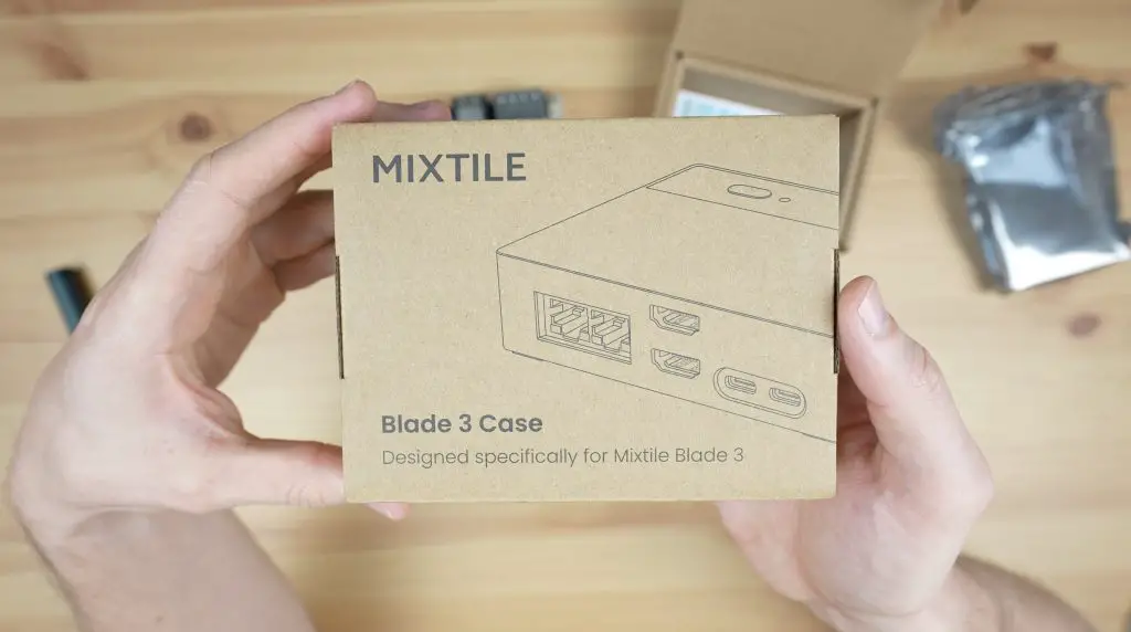
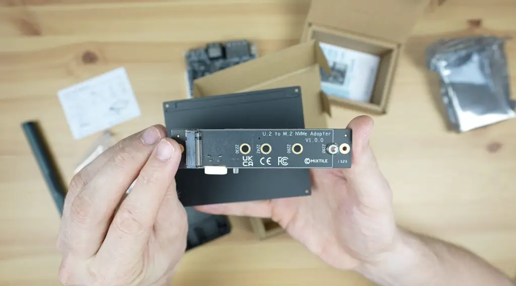
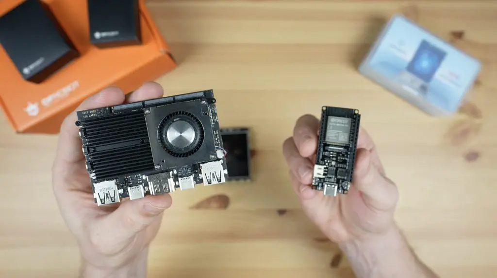
Today we’re going to be taking a look at the Blade 3, a new SBC from Mixtile which was successfully funded on Crowd Supply in June. The Blade 3 is based on the Rockchip RK3588 SOC (System on Chip).
I’ve tested a couple of boards that run this RK3588 SOC recently, but this one has a trick up its sleeve. It’s designed to be stackable to make up compact clusters with a 4-lane PCIe Gen 3 interface between each board in the cluster.
Here’s my video of the Blade 3, read on for the written review;
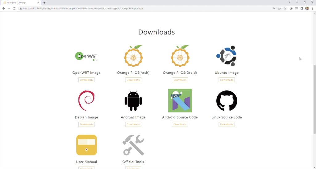
From the Crowd Supply page, the Blade 3 with 4GB of RAM and 32GB of storage sells for $229 and the 16GB version with 128GB of storage sells for $369.
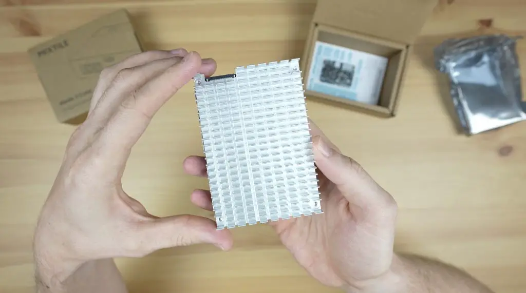
This does include a large passive heatsink pre-installed but even with the included storage as well, it is on the upper end for SBCs with this processor.
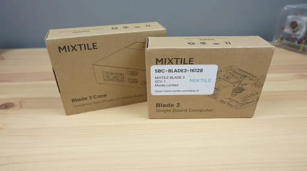
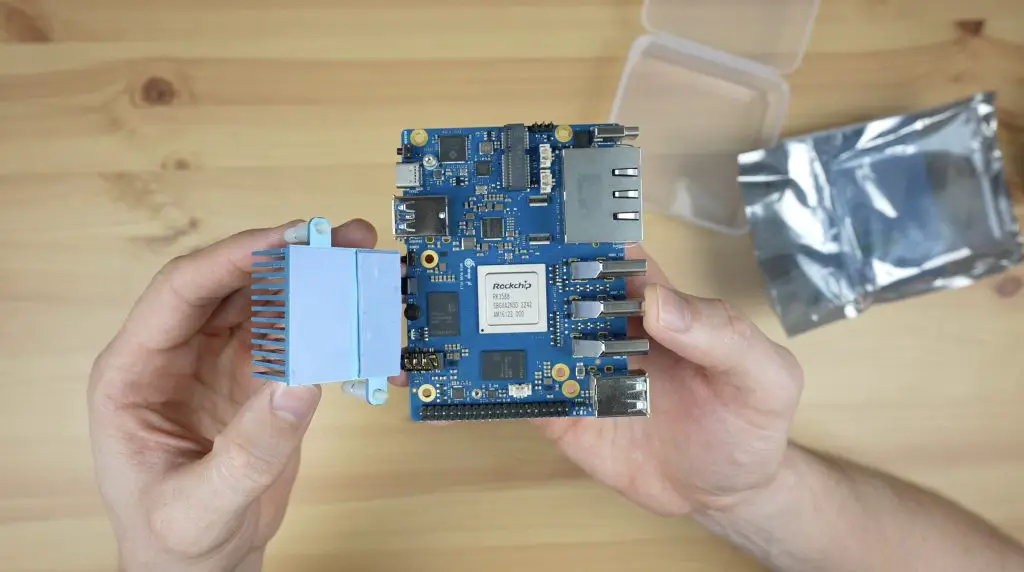
The Blade 3 comes in a branded cardboard box and includes a large passive aluminium heatsink on the back. Also included in the box is a brief quickstart guide, but most of their documentation is available from their website.
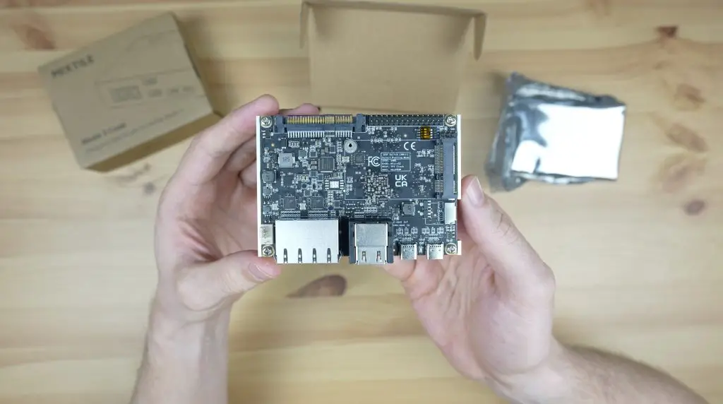
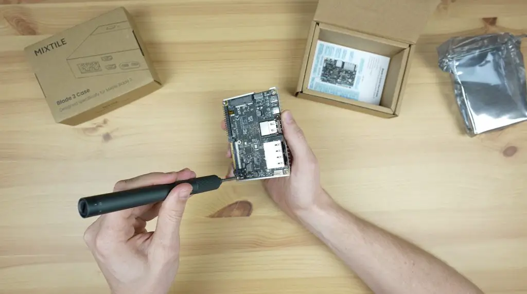
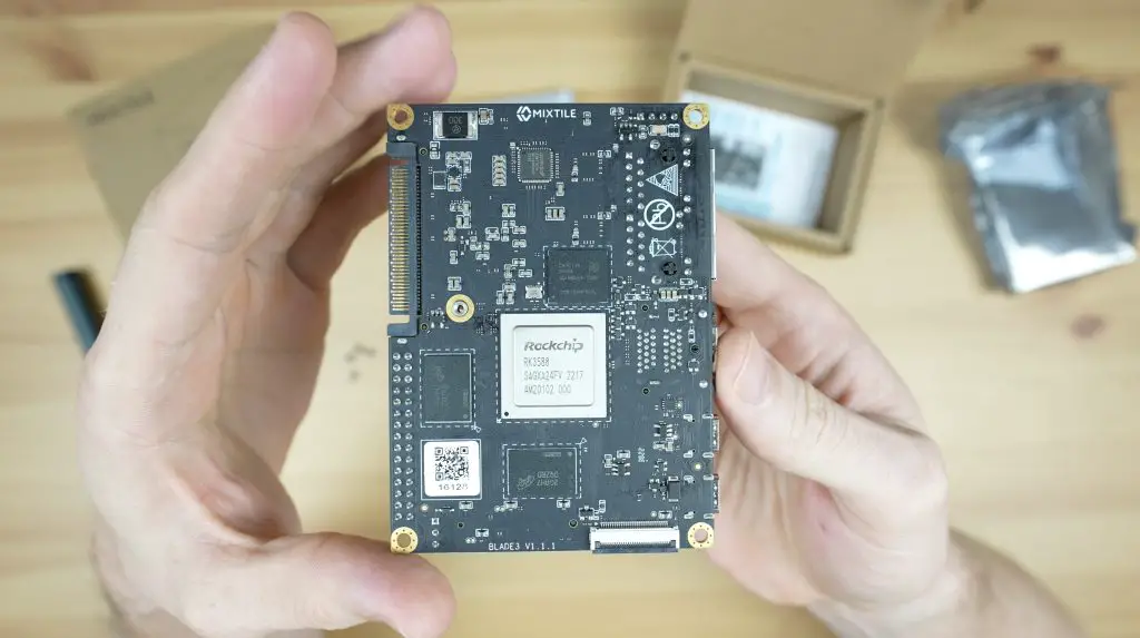
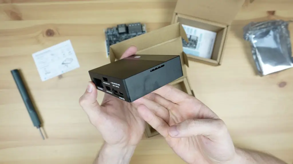
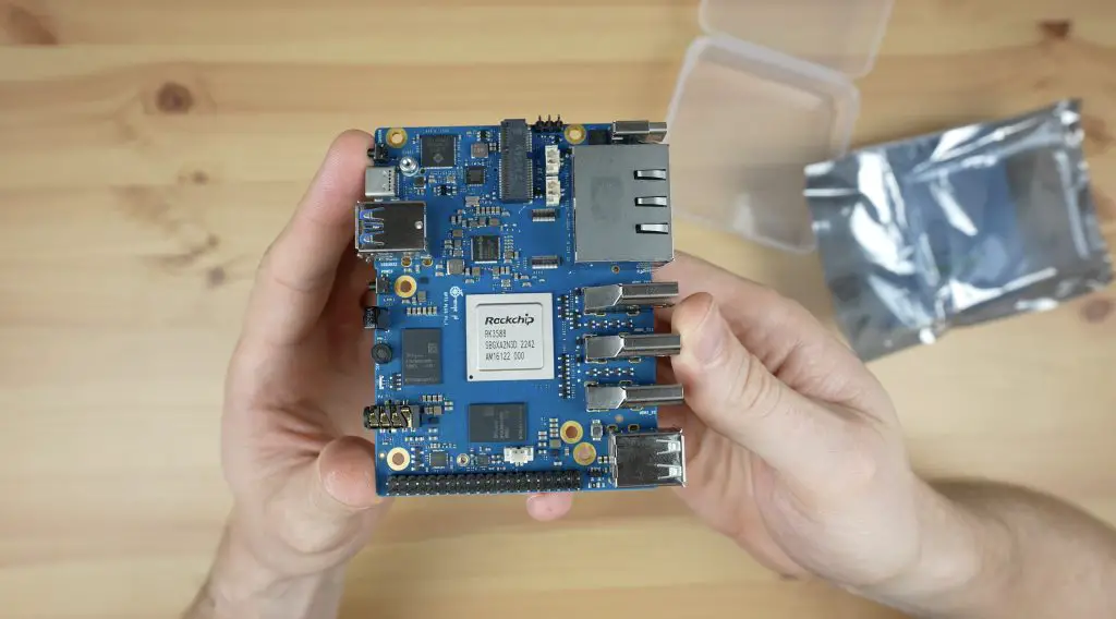
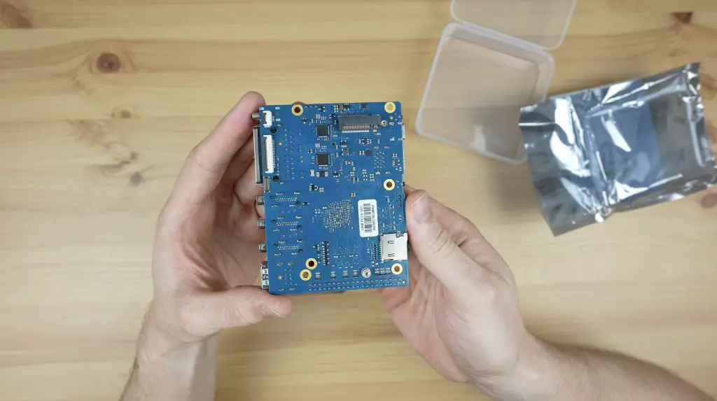
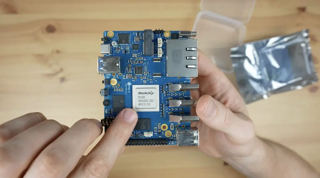
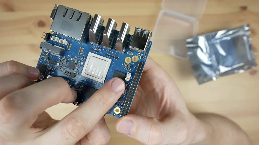
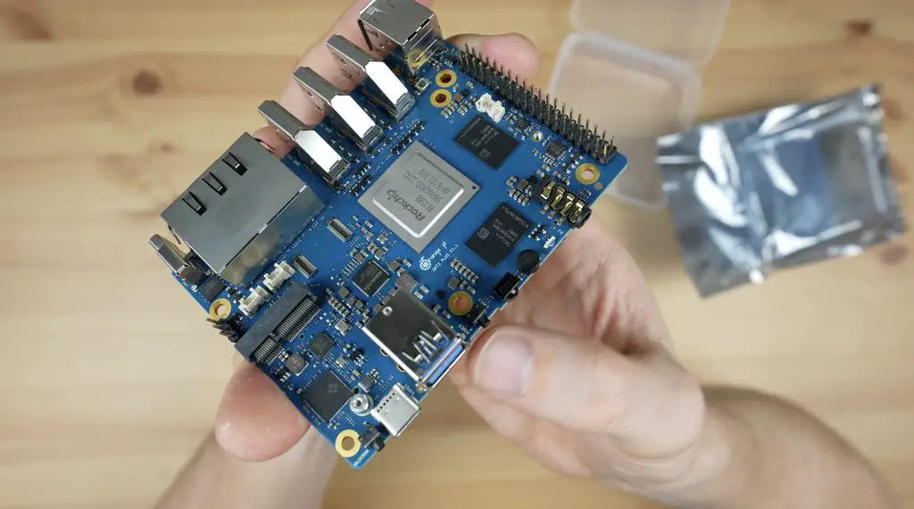
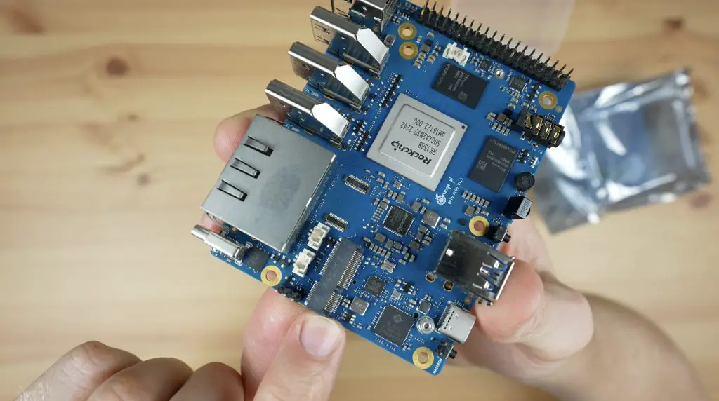
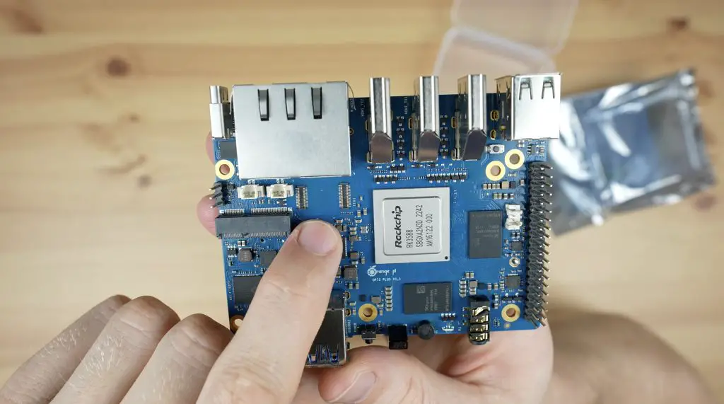
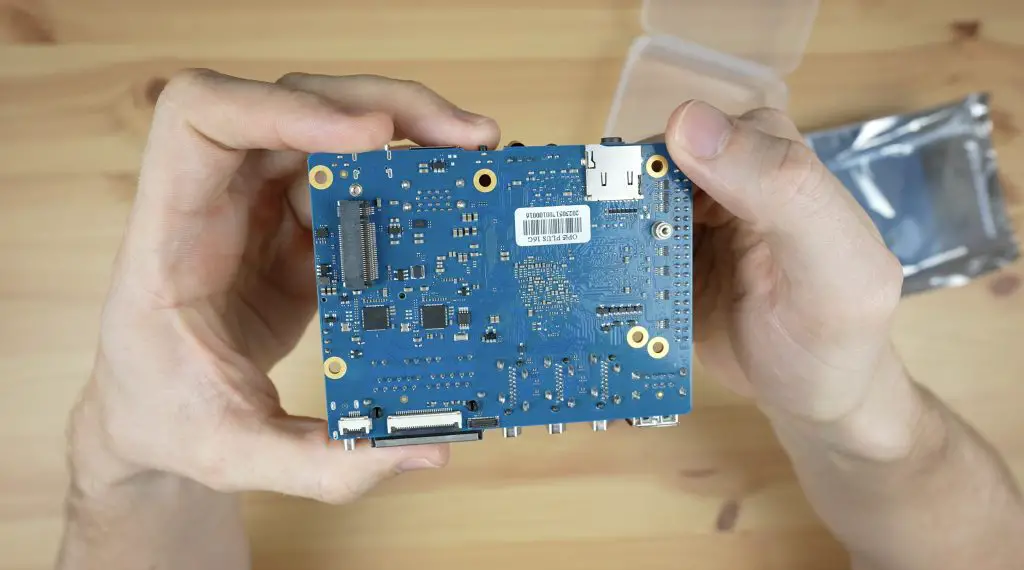
It is in a Pico ITX form factor with the majority of its IO ports on one side. The processor is actually on the bottom of the board underneath the heatsink.
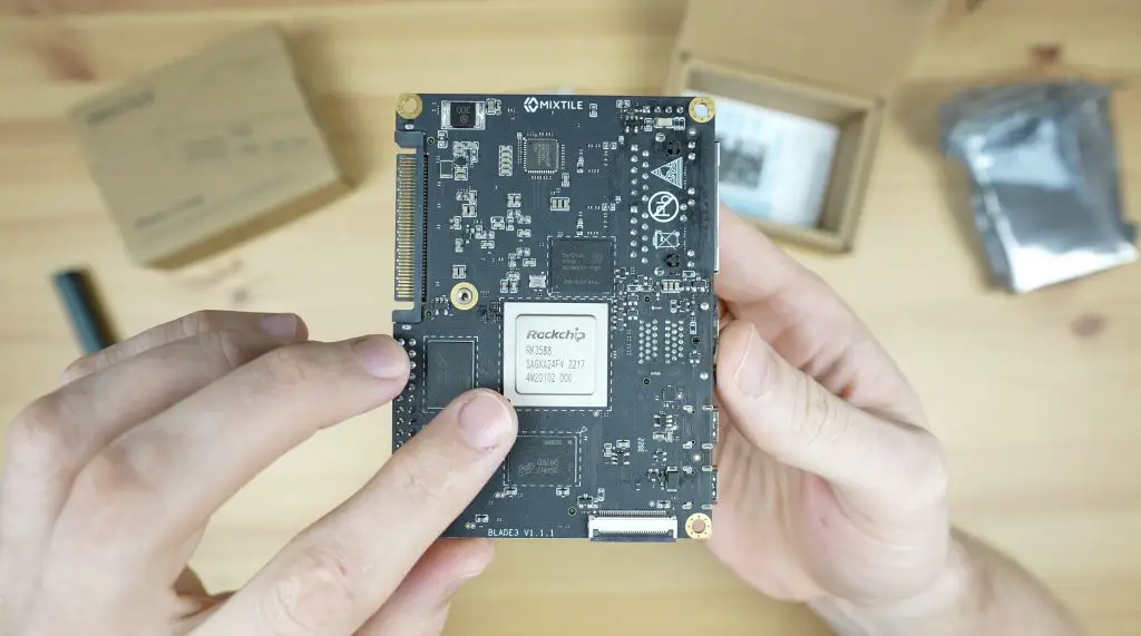
With it removed, in the centre we’ve got the Rockchip RK3588 processor.
This is an 8-core, 64-bit processor that consists of a 4-core Cortex A76 processor running at 2.4GHz and a 4-core Cortex A55 processor running at 1.8GHz. In addition to this, it’s got an Arm Mali G610 GPU.
Alongside the processor are the RAM chips, the Blade 3 supports up to 32GB of LPDDR4 RAM and above the processor is up to 256GB of eMMC storage. This is the version with 16GB of RAM and 128GB of storage.
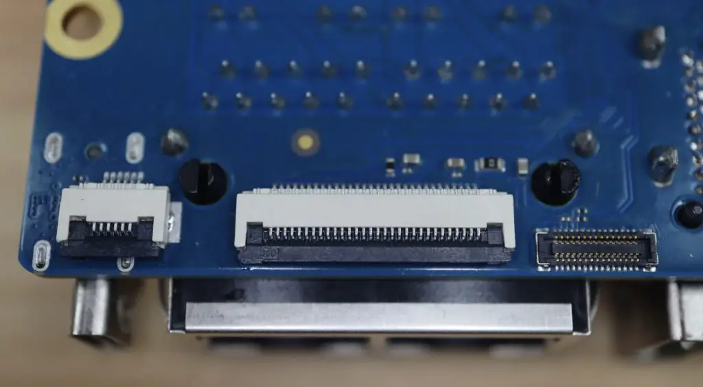
Also on the bottom of the board is a CSI camera port.
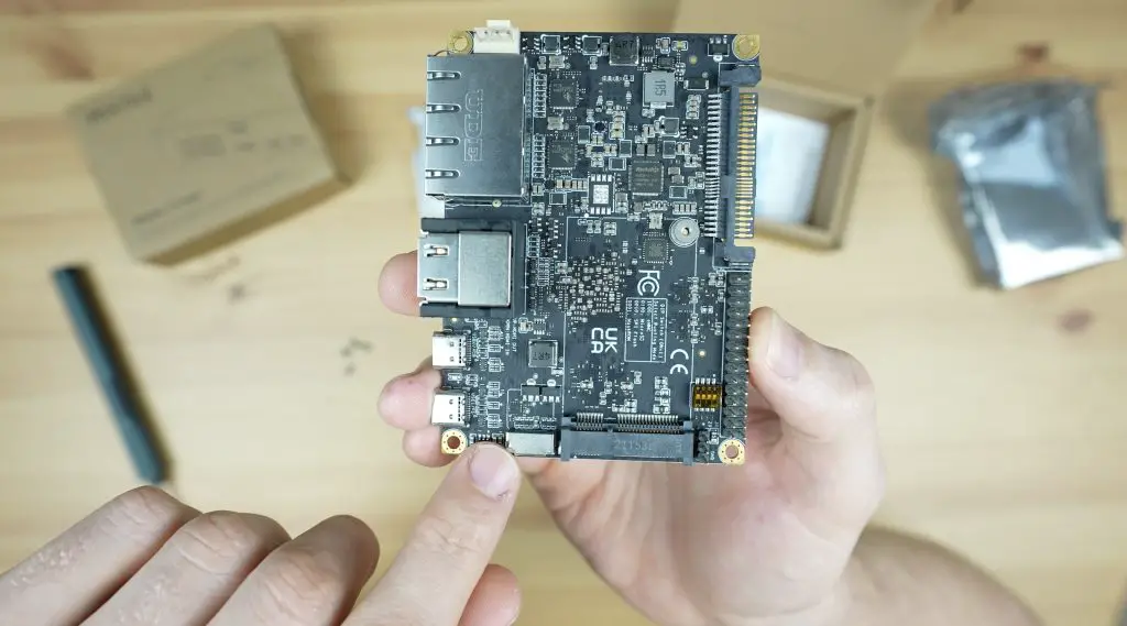
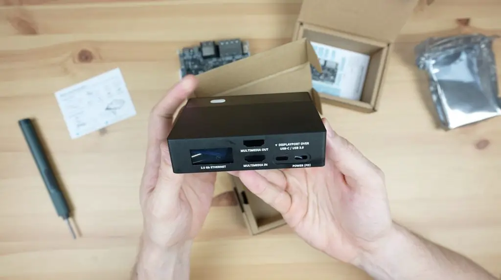
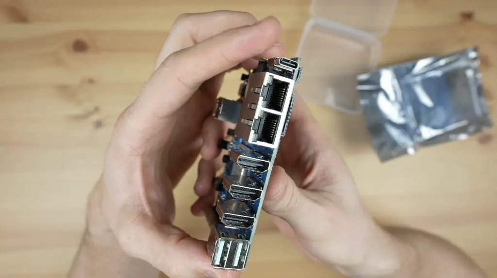
On the top of the board, we’ve got the main IO along one side. From left to right, this includes dual 2.5G Ethernet ports, and two HDMI ports, the top one is an HDMI 2.1 output which supports up to 8K60 or 4K120 and the bottom one is an HDMI 2.0 input which supports up to 4K60. Alongside those are dual USB 3.2 Gen 1 type C ports which also each support Display Port 1.4. The port on the right also supports Power Delivery 2.0 at up to 20V and 3A.
Behind the ports is a microSD card slot and next to that is a mini-PCIe socket that supports PCIe Gen 2.1
Alongside the mini-PCIe socket is a 30-pin GPIO header with a range of digital IO pins, I2C, SPI, USB 2.0, UART and I2S support. This roughly follows the same pin layout as a Raspberry Pi, albeit with a few pins missing.
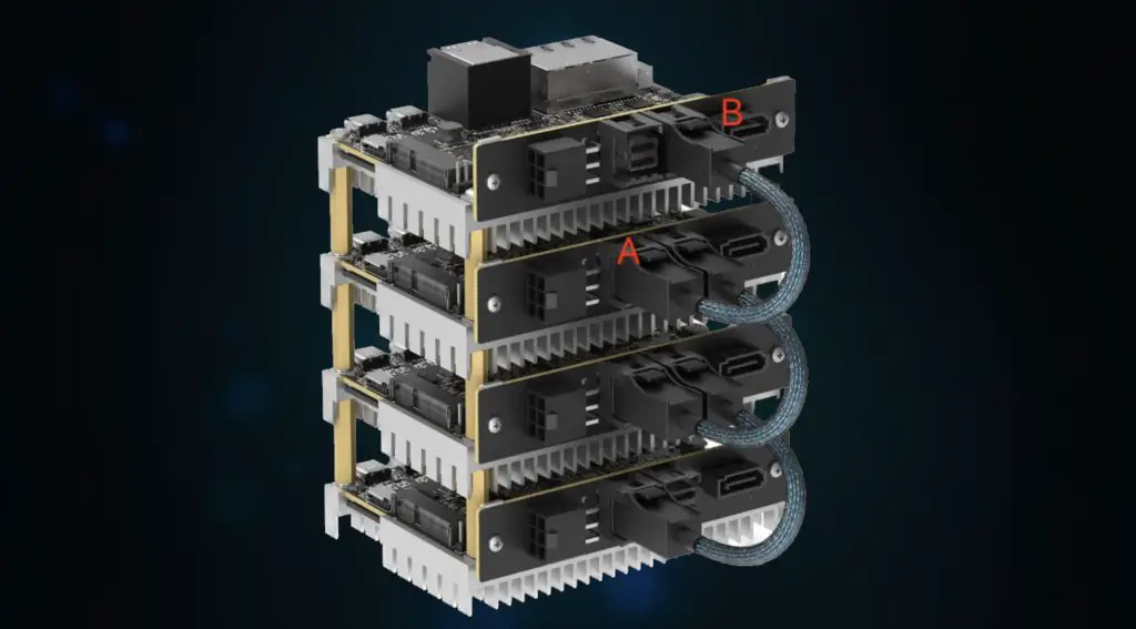
Next to this is the 4-lane PCIe Gen 3 interface in a U.2 port. This is the interface that makes the Blade 3 into a unique stackable design which would be great for building powerful clusters with a low latency interface between nodes. They say that you’ll be able to connect up to 75 Blade 3 SBCs together in 2U of rack space on a 19-inch chassis. With 75 Blade 3’s, that’s up to 600 processor cores and almost 2.5 terabytes of RAM.
It’s worth noting that at the time of writing this post, they have not yet released their full documentation around how this interface functions and I haven’t seen it working yet. They say that it will make use of a breakout board with two SFF-8643 interfaces, one PCIe A port and one PCIe B port. You’ll then chain the boards up by connecting B on the first to A on the second and so on.
They’ll also be releasing a 4-node cluster box that takes advantage of this interface to build a 4-node cluster with some integrated cooling fans.
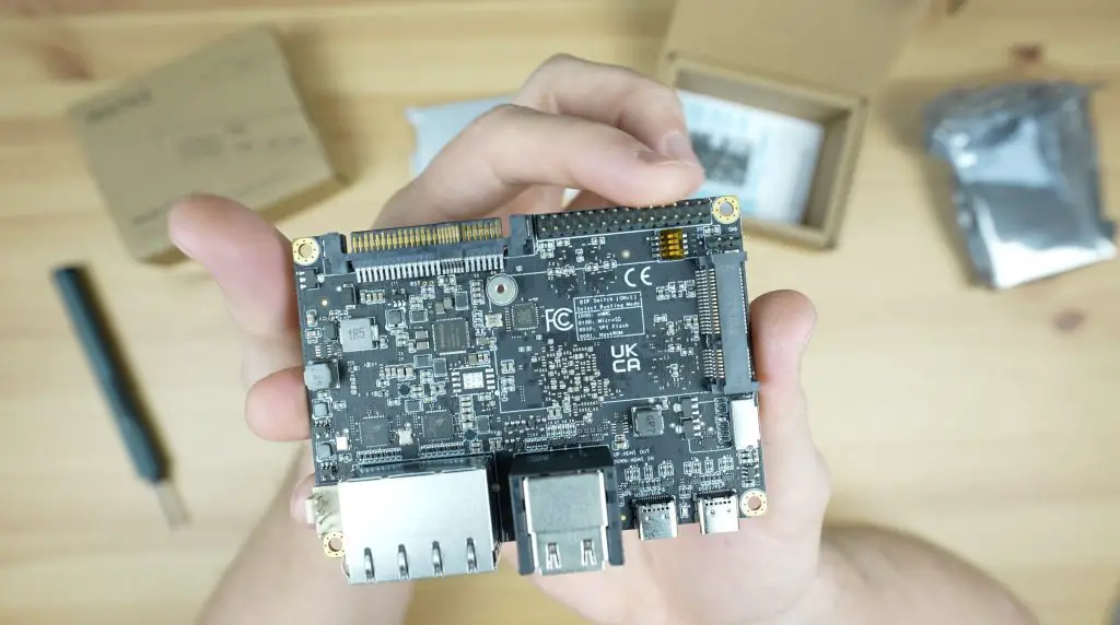
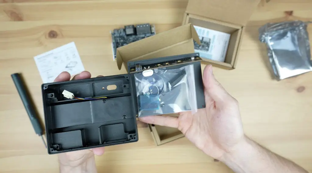
The Blade 3’s Aluminium Case
Mixtile have also designed this pretty cool case for it. This protects the Blade 3 and allows you to turn it into a portable mini-computer. The case also comes in a similar branded cardboard box.
It’s made up of two parts which are both made from aluminium. The larger half of the case looks like it’s been machined from a single block. They also include some tools and an instruction sheet to install the board in the case.
It’s also got a ventilation fan built into it with a small air outlet on the side. The ventilation fan actually cools the case and the case acts as a heat sink to the chip. It is a bit unconventional, but we’ll find out a bit later on how well this works.
The case also has a built-in breakout board to convert the U.2 port into an M.2 M-key port which allows you to install an M.2 NVME SSD as a boot or storage drive.
You don’t actually use the included passive heatsink if you install it into the case as the case becomes the heatsink. I’m going to run the tests on the board and it’s heatsink only as the case is an optional accessory and I’ll try the case out towards the end to see how it handles the heat from the CPU.
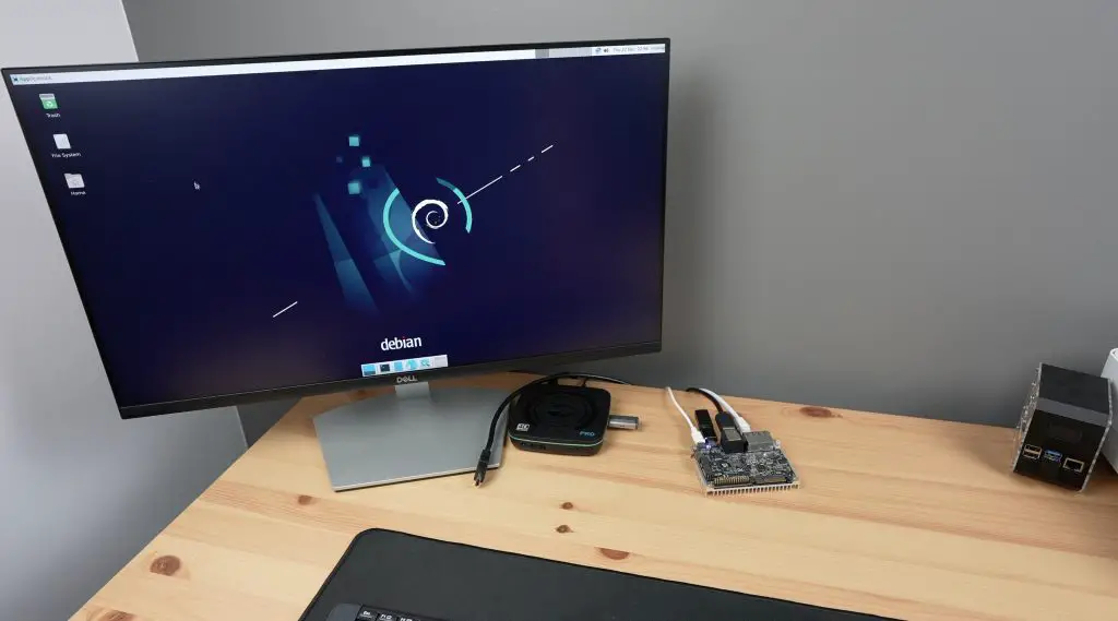
Testing The Included Debian Image
The board comes preloaded with a custom Debian 11 image, so it’s ready to run right out of the box. Just plug in power and connect a monitor, keyboard and mouse.
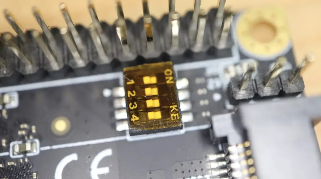
There are a couple of other boot options, you can boot from eMMC storage, MicroSD card or SPI Flash memory. These are selectable via four dip switches alongside the GPIO header.
These dip switches also allow you to enter maskROM mode to reflash the firmware. If none of them are selected then the CPU will automatically search through the boot options for any bootable media.
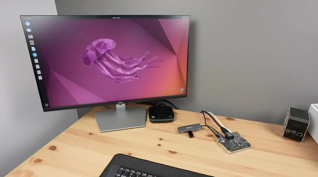
I did have some stability issues with the pre-installed Debian image. Mixtile have been routinely releasing updates to the image but it still seemed to crash every few minutes with my connected hardware even on the latest image. So, I ran the tests on the alternate Ubuntu image booting off a microSD card rather than eMMC storage.
Testing The Blade 3 On Ubuntu
I’m going to test the Blade 3 in the same way that I’ve tested other similar SBCs. We’ll first test some video playback at 1080P and 4K, then try running a Sysbench benchmark and finally we’ll take a look at power consumption.
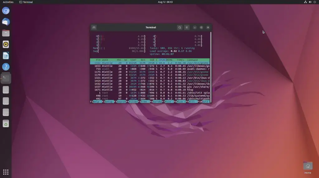
If we open up HTOP, we can see we have 8 processor cores listed, all relatively idle and then we’ve got our 16GB of RAM.
Youtube Video Playback
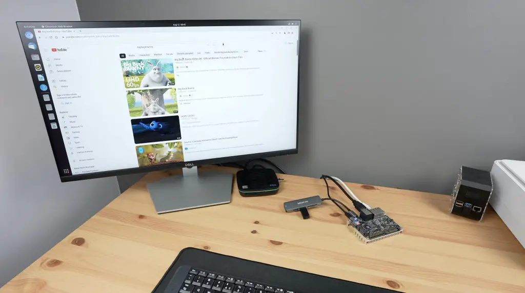
First let’s try playing back a YouTube video in the default browser – Chromium. I’m going to do this first at 1080P and then at 4K.
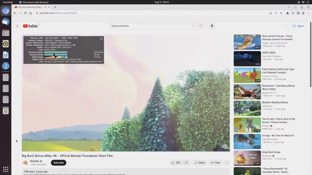
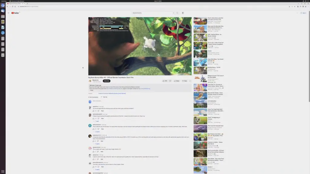
We’ll set the display resolution to 1080P. Then let’s open up Chromium, then go to YouTube and then open up Big Buck Bunny. I’ll open up stats for nerds and we can then set the playback resolution to 1080P as well.
Video playback in the window was near perfect, with only a few dropped frames at the beginning.
Playback performance was also really good running full screen.
Next let’s step it up to 4K. I’m going to first adjust the monitor resolution to 4K and then reopen Chromium and Big Buck Bunny. This time we’ll set the playback resolution to 4K as well.
In 4K, playback started off fairly well, we dropped a few frames in the beginning but after a few seconds of playback, it was also near perfect.
Opening playback up to fullscreen, it still handled 4K very well. After about 4 minutes of playback, we had only lost a total of 178 frames, which is barely noticeable.
If we open up HTOP, we can see we’re at around 20-30% CPU utilisation on the first 4 cores, which is relatively low compared to the other RK3588 boards I’ve tested. This indicates that the board is likely correctly using hardware decoding for video playback.
Mixtile have not yet released an Android image for the Blade 3 although they do say that this is in progress and will eventually be released. This will likely be the best for 4K video playback performance when it is available.
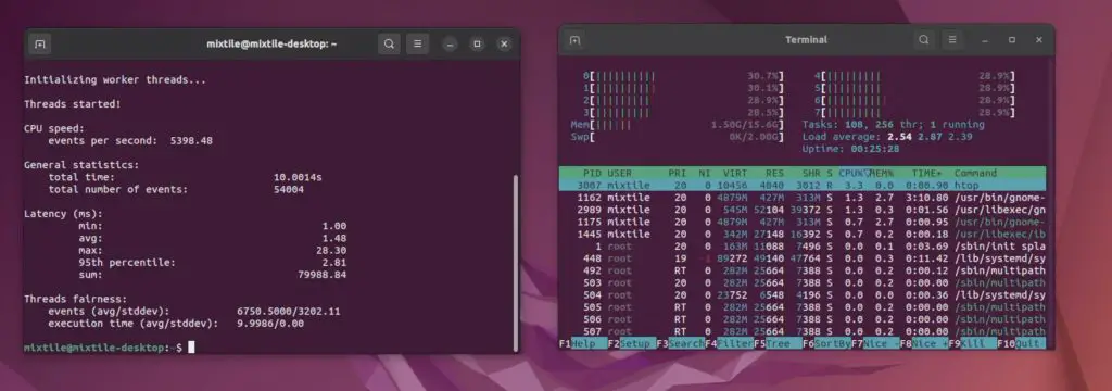
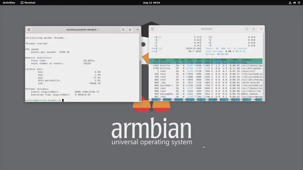
Running The Sysbench CPU Benchmark
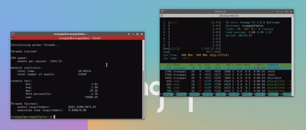
Next, let’s compare the performance of the Blade 3 with the Rock 5 B and Orange Pi 5 Plus by running the Sysbench CPU benchmark.
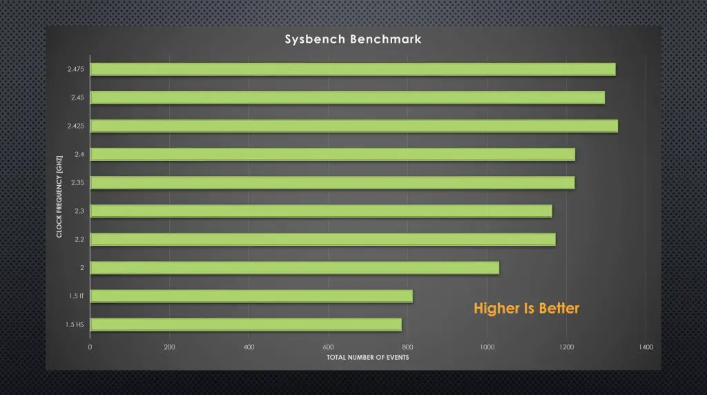
After 10 seconds we have processed a little under 5,400 events per second and we get a total score of 54,004.
Over three consecutive tests, the Mixtile Blade 3 managed an average score of 54,025.
For comparison, this is what the other similar boards that I have tested have managed over three consecutive tests;
The Blade 3’s performance is slightly higher than the other boards but could be because of the different OS being run as all of the others were tested on Debian. Out of interest I tried the test on Arabian and got slightly lower results, the average being around 53,495. So the results are definitely operating system dependent.
Overall, performance-wise, the Blade 3 is roughly on par or only slightly better than the Rock 5 Model B and the Orange Pi 5 Plus. This is to be expected running the same processor and similar hardware. It’s not a significant difference that you’d notice through day-to-day use.
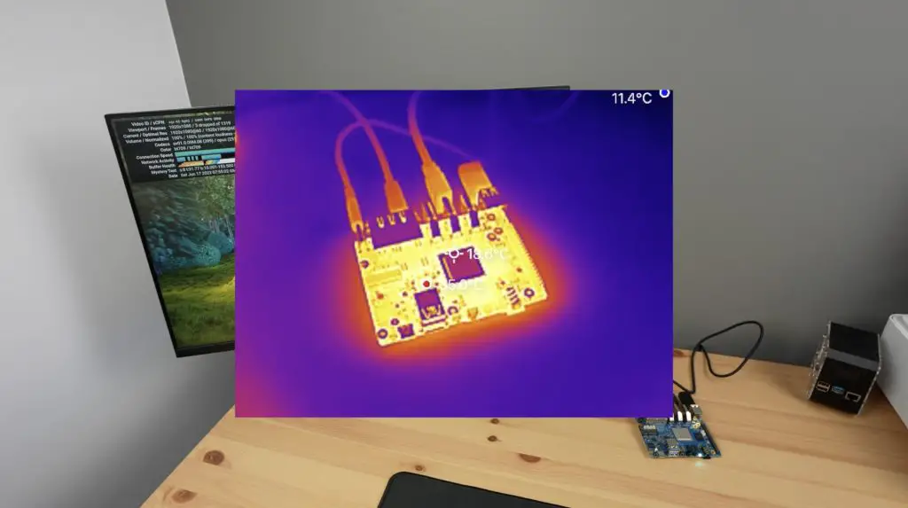
Thermal Testing The Blade 3, With & Without The Case
The included heatsink does a fairly good job of keeping the Blade 3 passively cool. After playing back 4K video for around 15 minutes, the Blade 3’s CPU was at a little over 65 degrees and the surface of the Blade 3 was at 52 degrees.
I then tried playing back 4K video for around 20 minutes in the case and although the case does get quite warm, the CPU temperature was a bit lower than with the passive heatsink. The CPU stabilised around 55 degrees with the surface of the top of the case at 30 degrees and the bottom at 40 degrees.
It’s worth mentioning that the room was at about 15 degrees for these tests, which is quite cold.
Power Consumption On The Blade 3
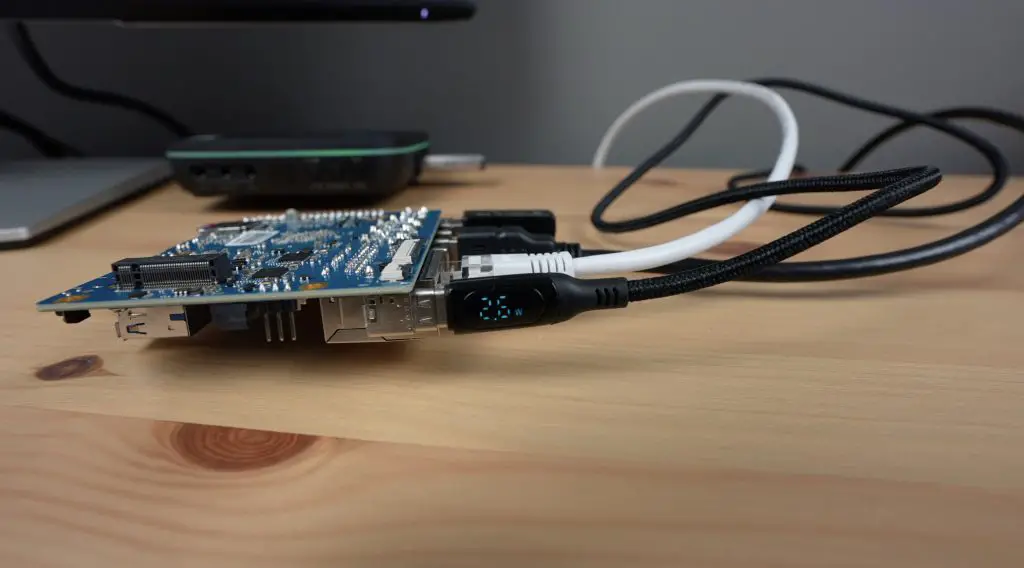
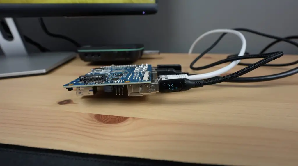
To measure the Blade 3’s power consumption, I used the meter on my power bank that supports Power Delivery.
This showed that the Blade 3 was actually running on Power Delivery, running at 15V. It runs at about 4.5W when idle and this goes up to 7-7.5W when loaded.
Some Identified Issues With The Blade 3
Aside from the instability of the Debian image, there are three things that I found a bit annoying on the Blade 3;
The case is nice and compact and protects the Blade 3 well but the fan is really loud. If you’re not using their operating system then the fan just runs at full speed continuously which is quite noisy on a desk.
The second is not having a standard USB type A port, so you have to use a dongle to plug in a keyboard or mouse. The USB type C ports are also a bit too close to use a compact dongle. If you squeeze one in, it puts pressure on the power cable alongside it, so it’s better to use a dongle or adaptor with a lead.
The third is the location of the microSD card slot. It is positioned so that the card has to be inserted from the inside and the surrounding ports and surface mount components make it difficult to actually get your fingers onto it to plug it in or remove it. I found myself fumbling to plug it in a number of times before it seated correctly.
Final Thoughts On The Blade 3
Overall I think that while the Blade 3 is expensive, they have used good quality components. They’ve used Micron RAM chips and SanDisk flash storage. Unfortunately, as with most of these boards, the software lets it down. At least this is possible to work on and fix and hopefully Mixtile will dedicate their attention to getting a stable release of Debian out.
I’d like to finish off with a reminder that crowdfunded projects carry some level of risk and that there is no guarantee that the final product will live up to the expectations of the project. Mixtile look like they have a capable team, they have a track record in electronics manufacturing and they’ve obviously completed their pre-production run, which has allowed me to have one. But that isn’t to say that this product is without risk – it is not yet a fully-fledged retail product.
That said, I definitely look forward to seeing what its clustering capabilities look like in future!
Let me know what you think of the Mixtile Blade 3 in the comments section below and if there is anything else that you’d like me to try on it.
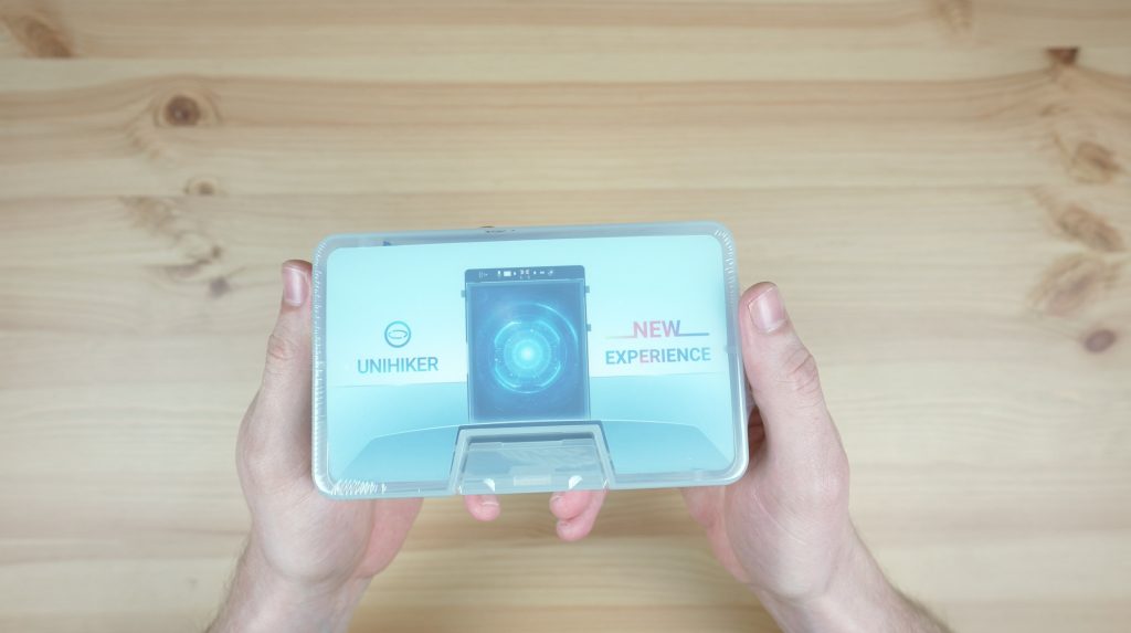
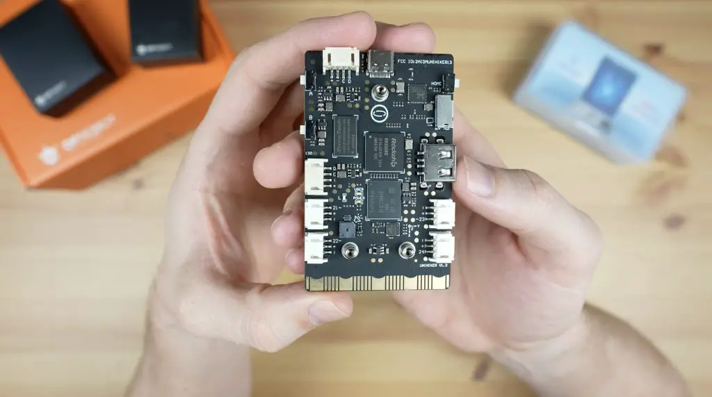
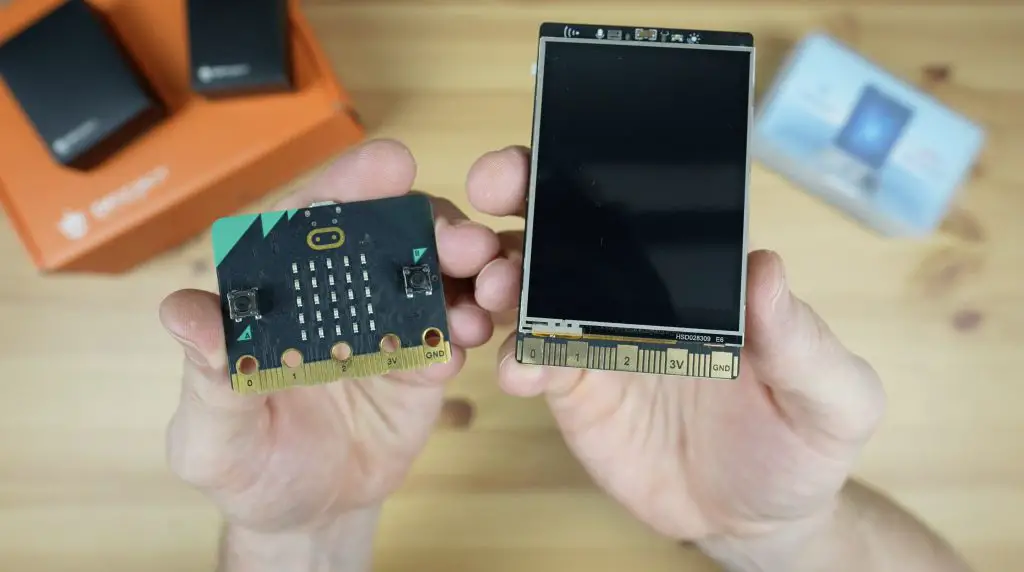
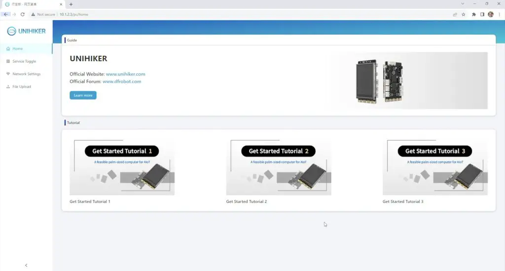
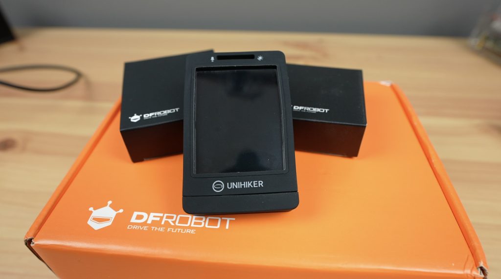
The Unihiker is a new single-board computer from DFRobot which is a bit different to the ones that I usually take a look at on my blog.
The Unihiker is designed to bridge the gap between a traditional single-board computer (SBC that runs an operating system like Linux, and a microcontroller like an Arduino. It’s actually got both of these onboard.
It’s got a traditional CPU, memory and storage that runs Debian 10, and it’s coupled with a microcontroller that controls all of the IO, including the onboard sensors and the expansion ports. So it has the flexibility of an SBC, allowing programming and running programs directly from the device, but it also has the timing reliability and robustness of a dedicated microcontroller.
It’s also got an onboard 2.8″ touch display, built-in WiFi and Bluetooth and it’s equipped with a range of onboard sensors.
Here is my video review and testing of the Unihiker, read on for the written review:
Some of the above parts are affiliate links. By purchasing products through the above links, you’ll be supporting my blog, at no additional cost to you.
Taking A Look At The Unihiker’s Hardware
The Unihiker comes in an opaque plastic case along with an included USB C programming cable and a range of white connector cables to connect sensors and modules to. The Unihiker itself if packaged in a black bubble sleeve for additional protection within the case.
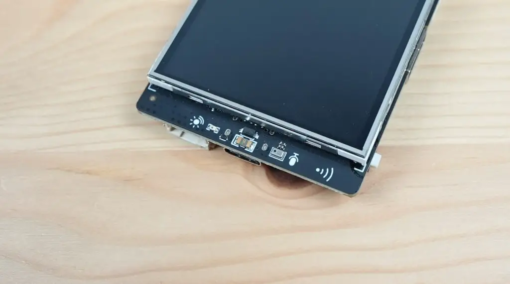
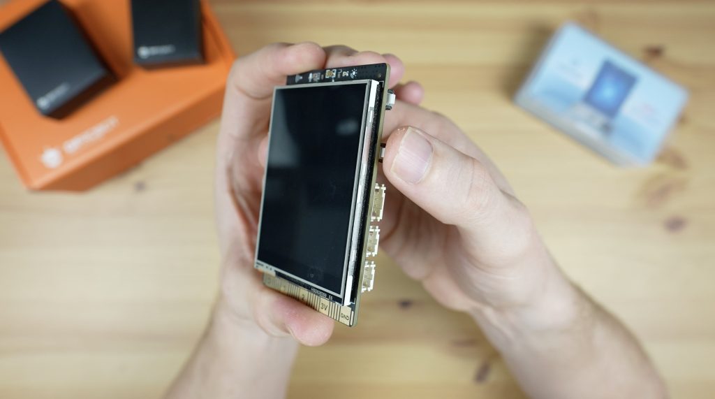
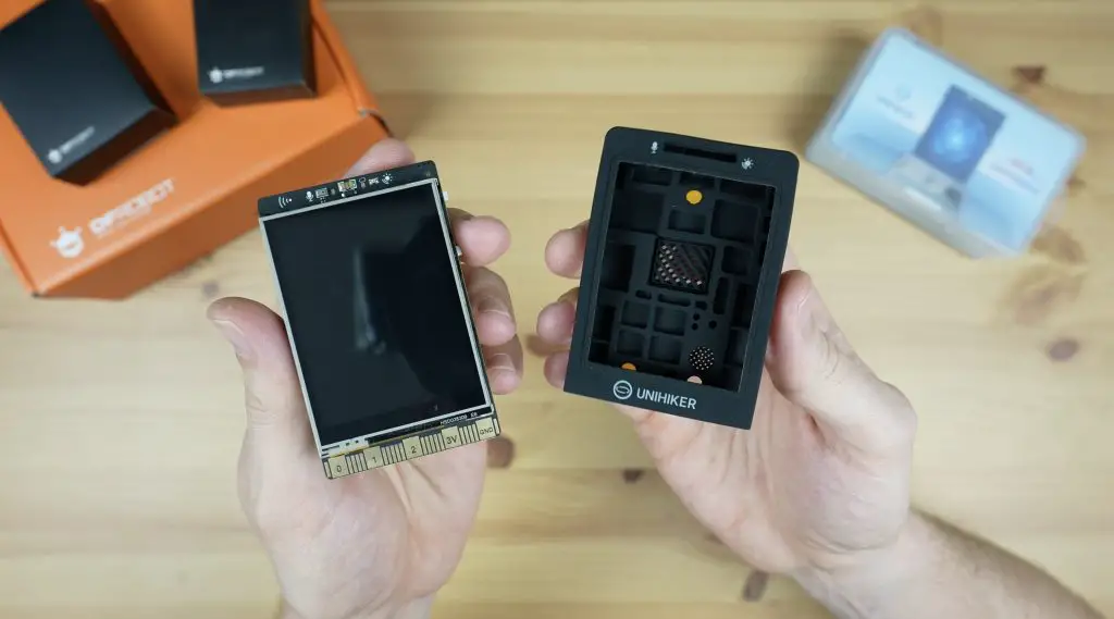
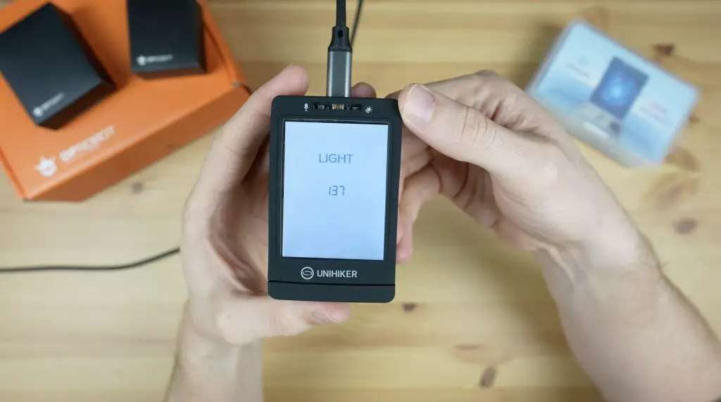
At the front is the 2.8″ touch display and along the top of the display is the light sensor and microphone.
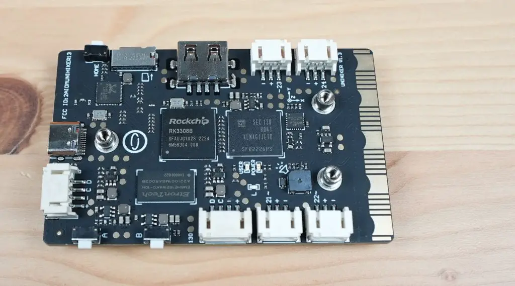
On the back is the processor, which is an RK3308 64-bit, 4-core processor running at 1.2GHz. So it’s not exactly a powerhouse, but it’s plenty for what the Unihiker is designed to do. It’s got 512MB of DDR3 RAM and 16GB of onboard eMMC storage.
It is coupled with a Gigadevice RISC-based microcontroller running at 108Mhz which 64kB of Flash memory and 32kB of SRAM.
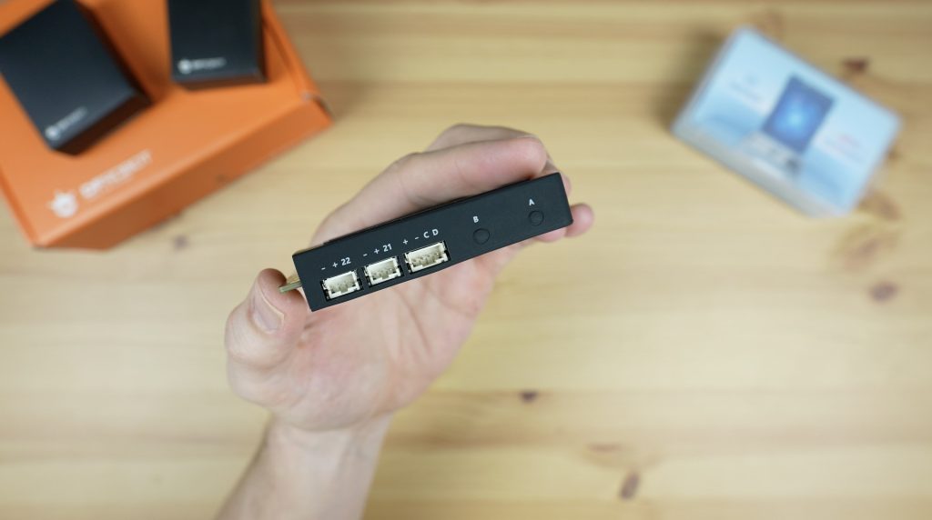
On the back is also a microSD card slot, a range of plugs to connect sensors and actuators to, as well as a buzzer, gyroscope and accelerometer.
Along the edges, we’ve got two pushbuttons on the right-hand side and then a home button on the left. These are programmable, so they can be used to add functionality to your projects.
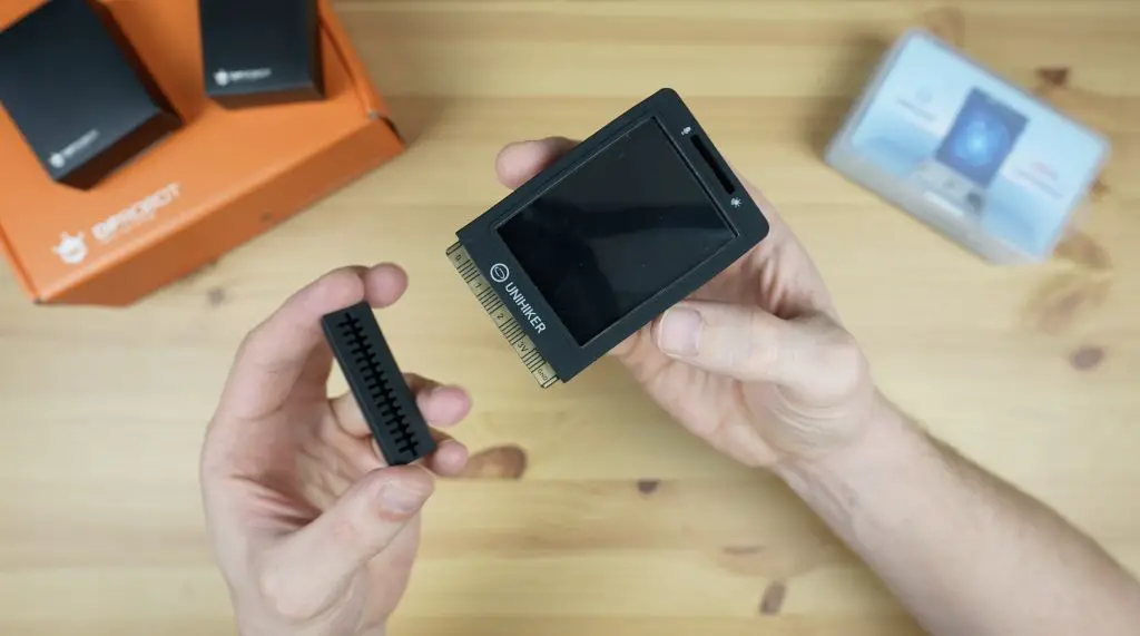
Along the bottom is the edge connector. This is essentially an expansion connector that allows access to additional IO pins and interfaces. This connector follows the same format as the connector that is used on a Micro:bit, so I assume it would be compatible with most of the expansion boards available for that platform.
DFRobot also make a silicon case for the Unihiker which fits snugly around it while still allowing access to all of its ports and sensors. The case also comes with a removable protector for the edge connector at the bottom. You can get it in red or green as well if you don’t like black.
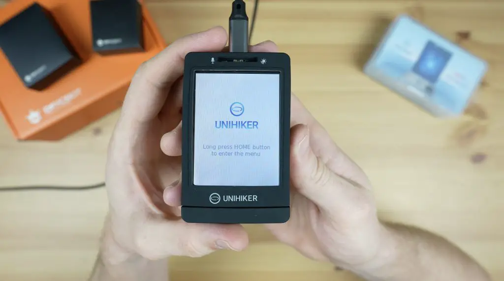
First Boot & Look At The Operating System
The Unihiker comes preloaded with a Debian-based operating system, so you just need to plug it into your computer or power source to boot.
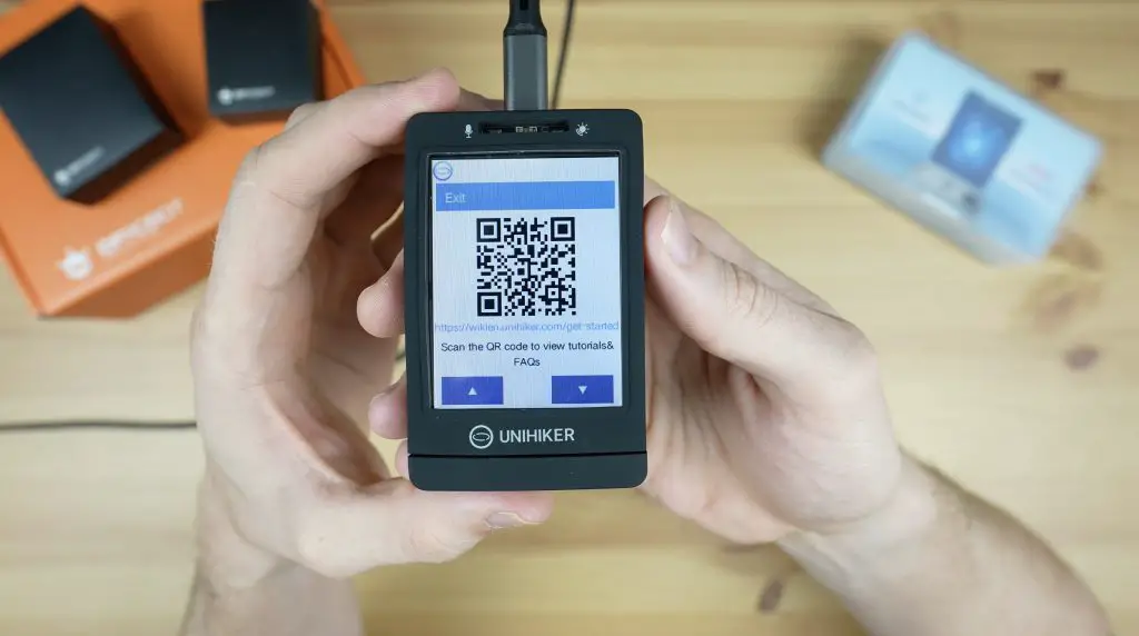
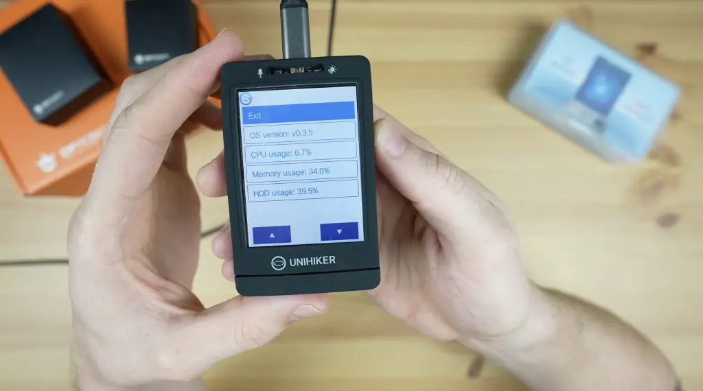
Once it has booted up, the buttons on the sides along with the touch display allow you to navigate through the menus to access documentation or tutorials, run programs directly from the device, connect the Unihiker to your network or make changes to settings.
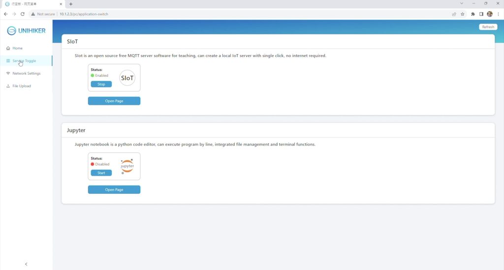
Programming the Unihiker is done through a network connection with a few different options:
It can be directly attached to a computer through a USB cable and can then be accessed as an RNDIS device with a fixed IP address [10.1.2.3].
You can connect it to your WiFi network and then use a computer, tablet or even your mobile phone on the same network to program it.
You can create a hotspot on the Unihiker and connect to it directly from a computer, tablet or phone.
And if none of those options appeal to you, you can even plug a USB Ethernet adaptor into its USB port and connect it to your network via. Ethernet.
I’m going to go with the first option, so let’s plug the Unihiker into a computer and try to load a program onto it.
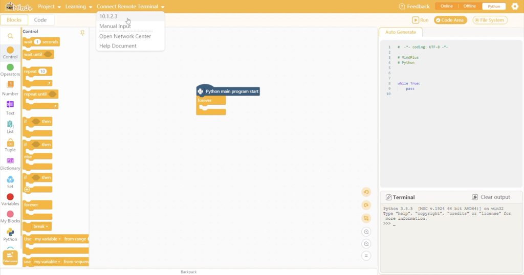
As mentioned earlier, if you connect the Unihiker to your computer via USB it can be programmed using its fixed IP address. We can also enter this address [10.1.2.3] into the browser on the computer that it is connected to and we can then access its local web service.
From this page, we can access documentation and tutorials, toggle services on or off, configure its network connection and upload files to the device.
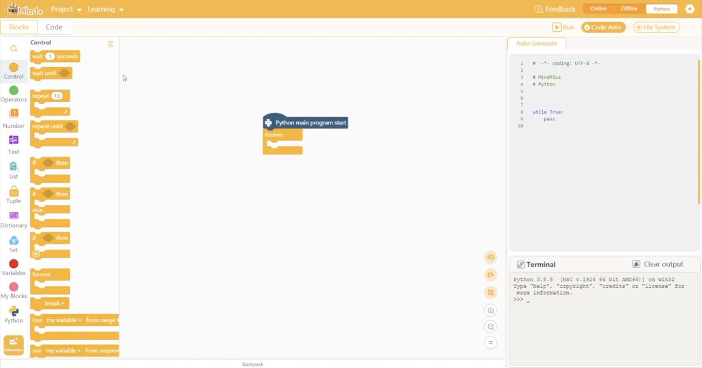
We’re going to try to create a basic program to run on the Unihiker using the DFRobot programming package called Mind+.
Creating Our First Project
After starting a new blank project, we can add the Unihiker as an extension and then connect to it. Mind+ will then automatically establish the connection and update all of its required libraries.
We can then either use the drag-and-drop block coding interface or the Python code area to make up a program. Let’s start by creating a program to show the level of light detected by the onboard sensor. We do this by just dragging function blocks in from the toolbar on the left and we can then make any necessary adjustments to parameters.
Then we click on run to upload the code to the Unihiker and execute it.
So that was really easy to get working and it took less than a minute to program. If we hold the Unihiker up to different levels of light, the indicated value on the display changes as we’d expect.
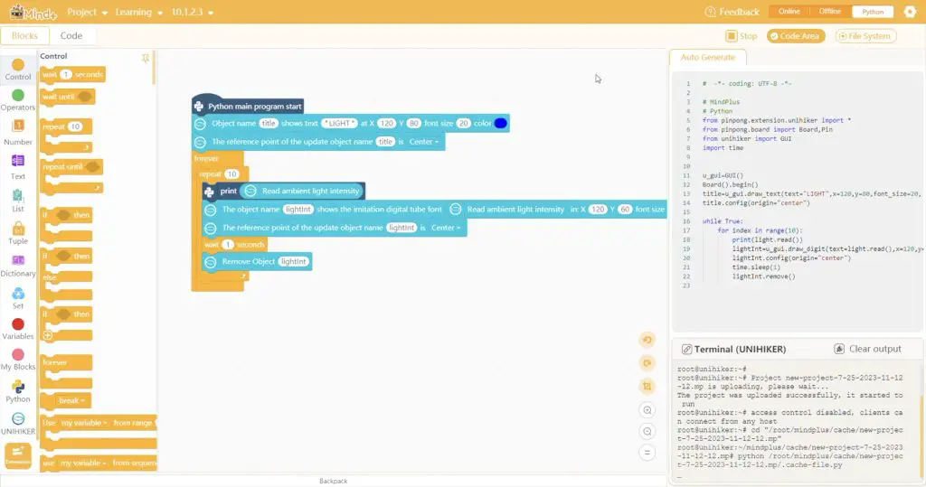
Creating An Environment Sensing Project
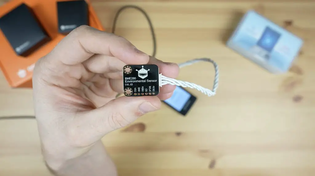
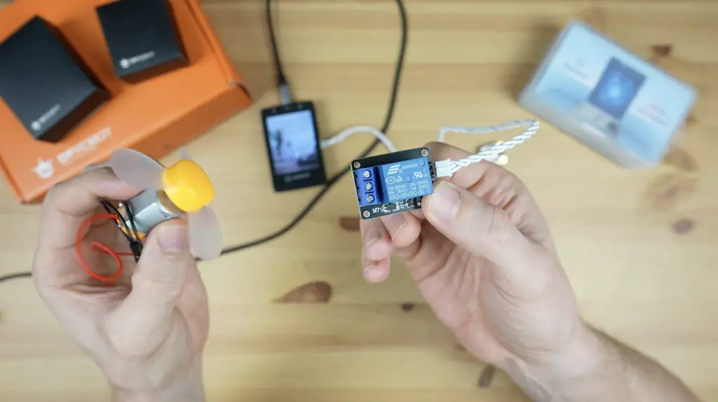
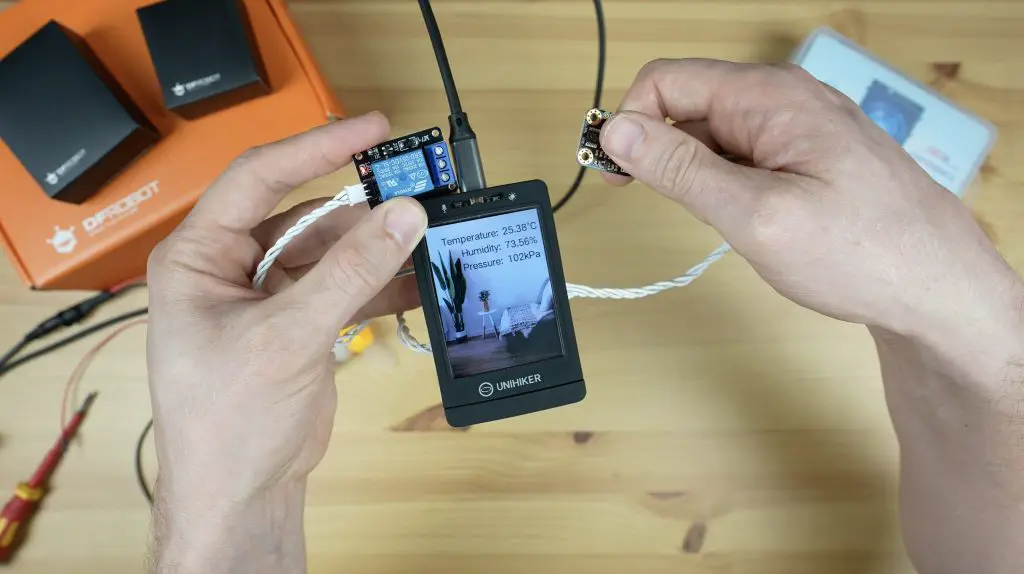
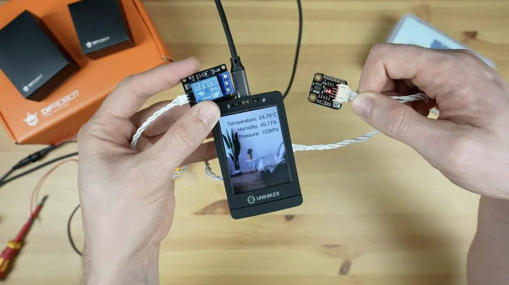
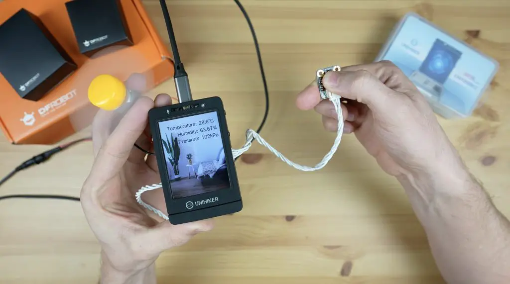
Now let’s try to build something a bit more complicated. I’m going to use a BME280 environment sensor to display the ambient temperature, pressure and humidity on the display. This sensor uses a Bosch sensor and an I2C interface to provide these three parameters to the Unihiker.
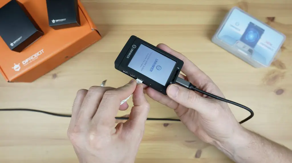
We’ll start by plugging the BME280 sensor into the I2C port on the side of the Unihiker.
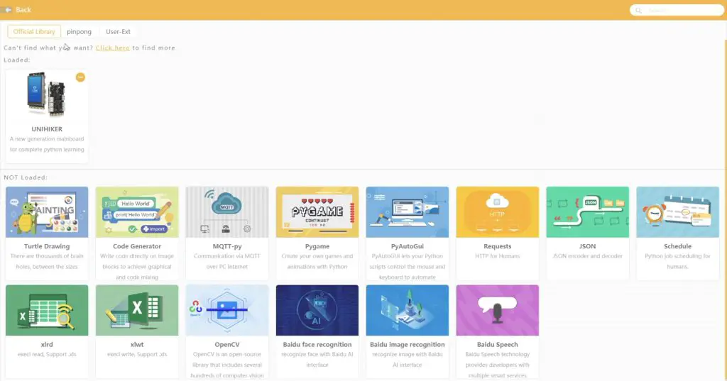
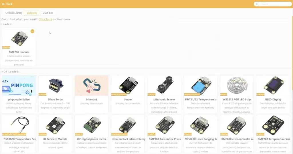
We can then add the BME280 extension to the project. This tells the Unihiker to import the libraries needed to communicate with the sensor and adds the function blocks to the toolbar on the left to get information from it.
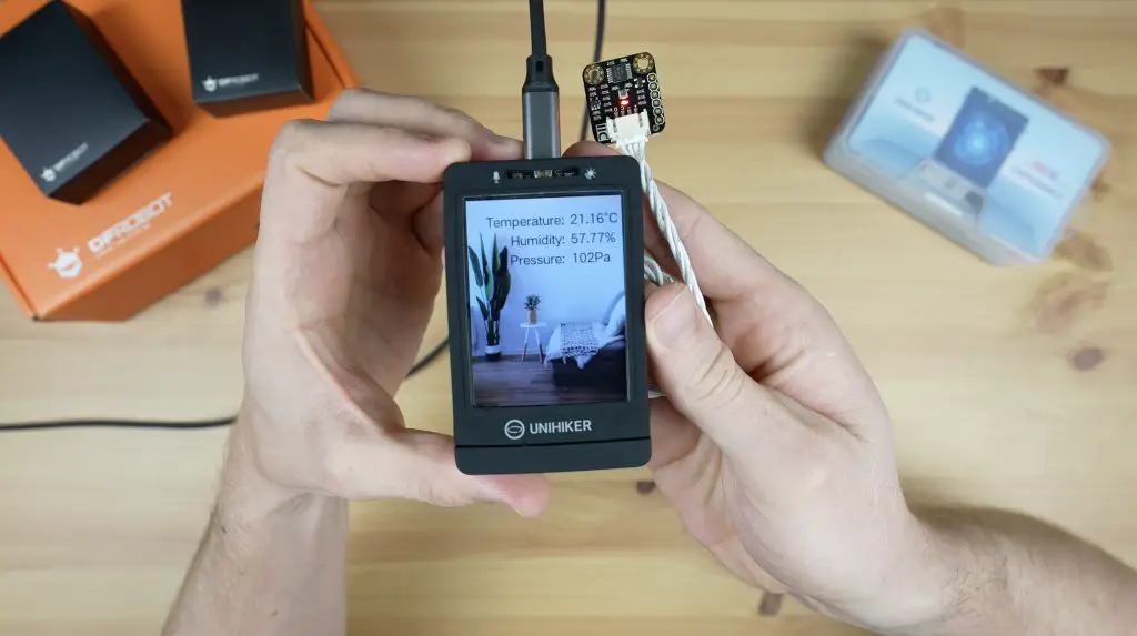
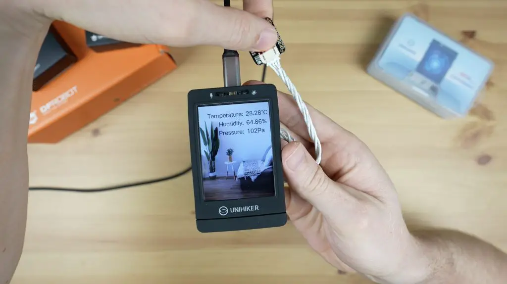
Now we can drag and drop text and fields to display these on the Unihiker. I have also included an image of a room as the background for the environment monitor.
As we did previously, we can click on run to upload the code to the device and we can then see it running.
Holding a finger on the sensor warms it up and changes the output values.
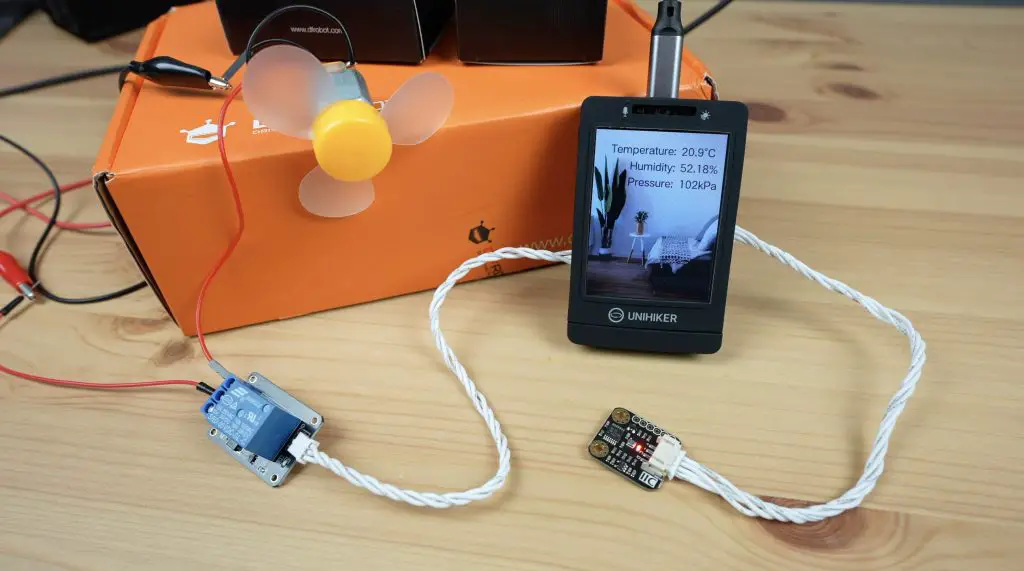
We can also take it a step further in Python rather than using block coding. Let’s try turning on a fan if the temperature gets too high.
For that, I’m going to add a relay module to one of the digital ports on the side and I’ll then connect the fan to the relay module.
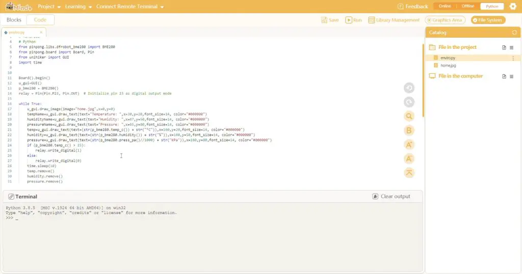
Now we need to write a script to turn the fan on when the temperature exceeds a certain setpoint and then try to run it again. As a starting point, I’ve just copied the generated script from the block code and I’ve then added some additional lines to define the operation of the digital pin for the relay and an if statement to turn the fan on if the temperature exceeds 25 degrees.
Let’s upload and try it out.
The relay module is initially off as we’re below 25 degrees. If I put my finger onto the BME280 sensor, which will warm it up, then the temperature will then exceed the setpoint and the relay switches on. When it cools down again then the relay turns off.
Now if we hook the fan up to it, the fan comes on and turns off automatically when we do the same thing.
Here’s a link to download the Mind+ code for all three of the above sample projects:
So you can see from these examples that it was really easy to get these projects up and running on the Unihiker and there is a lot of flexibility to easily build upon your projects. You don’t need to have an advanced knowledge of programming or electronics to get some simple projects running on it.
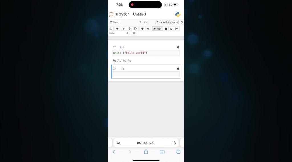
I also really like the flexibility in programming options, even being able to program it using Jupyter your phone or tablet. This makes it a great, compact platform for education and tinkering.
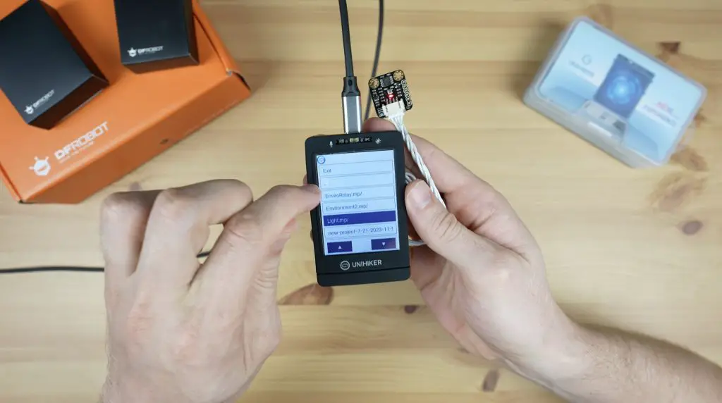
Once you’ve uploaded a program to the Unihiker, it is also stored for you to re-run directly from the device at a later stage if you’d like to. You can use the menu buttons to access the code which has been transfered to the Unihiker and then run it from the device. Each project is saved in it’s own folder, so you can have a number of scripts, sketches or programs ready to run on the device.
At the time of writing this review, the Unihiker is $79.90 from DFRobot’s web store. I think this is pretty good value for what is essentially a compact single-board computer, a touch display and a microcontroller.
Let me know what you think of the Unihiker in the comments section below and let me know if you’ve got any project ideas that you’d like to see me try on it.
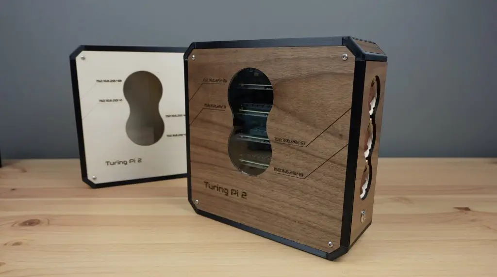
Today we’re going to be using the new Creality Falcon 2 40W laser cutter and engraver to make up a Mini ITX computer case for my Turing Pi 2.
I previously made a case for it out of clear acrylic but I’ve recently seen a number of really cool-looking designs for computer cases that incorporate wood panels. My last case was made up of 3mm sheets of acrylic, which I could just swap out for 3mm plywood, but I want to improve on the design and make it look a bit more professional.
Here’s my video of the build, read on for the write-up;
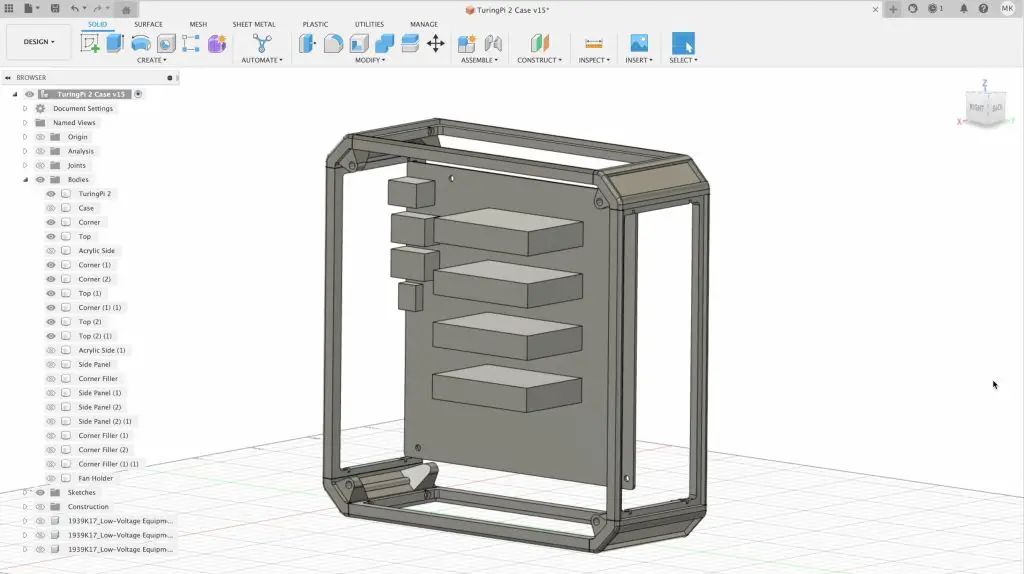
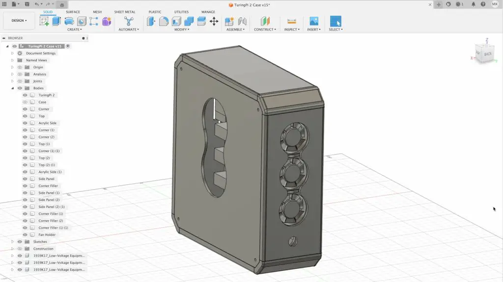
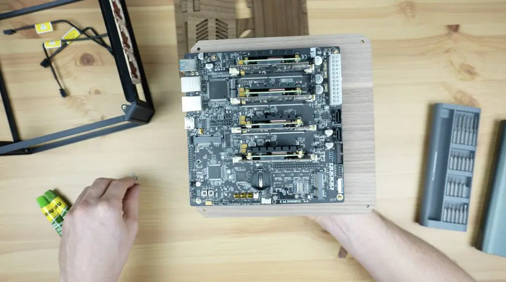
To design the new case, I used Fusion360. I started out by rough modelling the Turing Pi 2. I then designed a frame to hold the plywood panels in position around the Turing Pi 2 to form the case.
This frame would better finish off the corners and edges of the case and I think the two-tone contrast between the black plastic components and some walnut wood panels will look quite good. The frame is primarily made up of four 3D-printed corner pieces and four side panels and these will then screw together to form the main shape of the case and to hold the plywood panels.
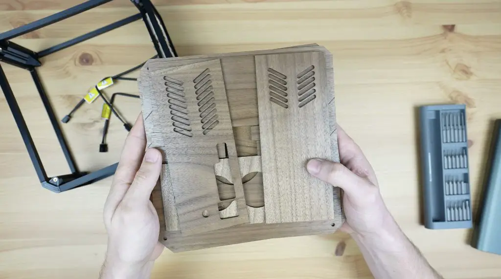
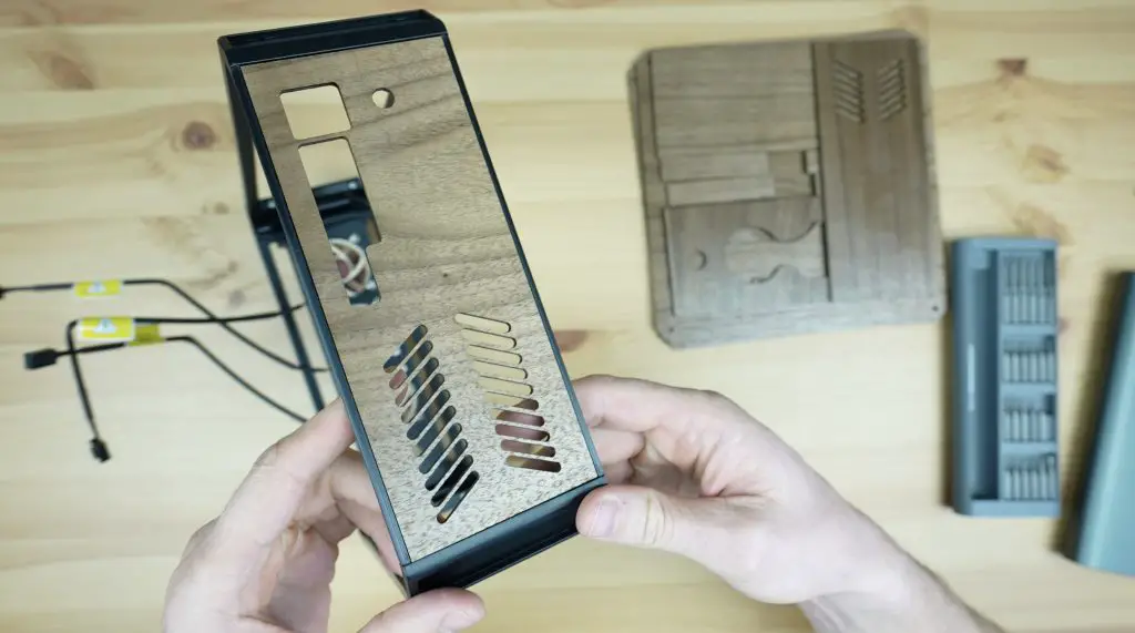
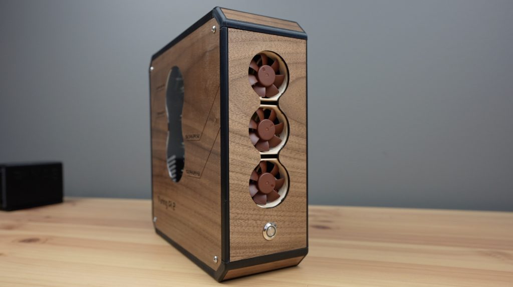
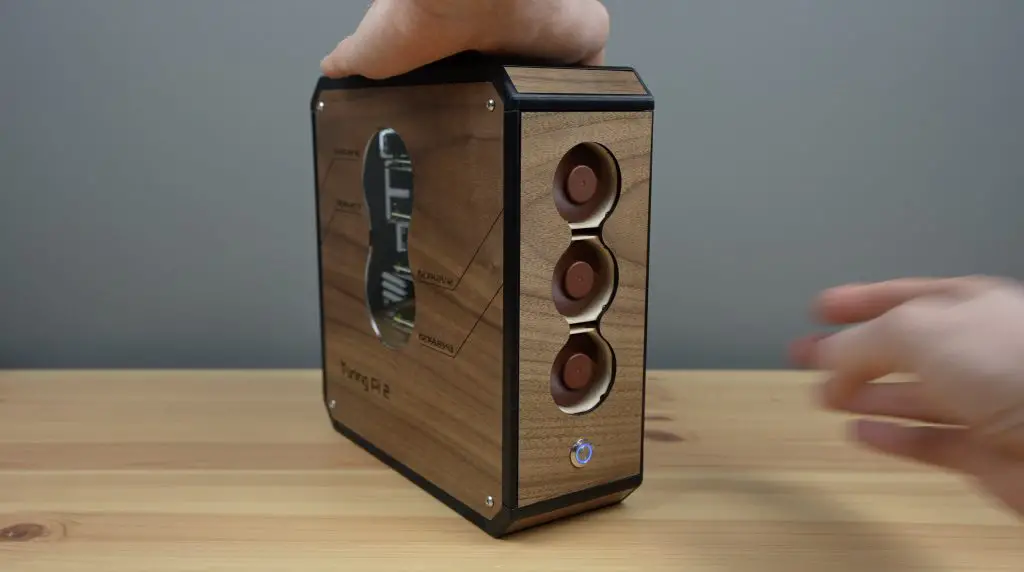
For the plywood panels, I have kept the same three-fan and power button layout at the front, but I’ve redesigned this to add to the aesthetic.
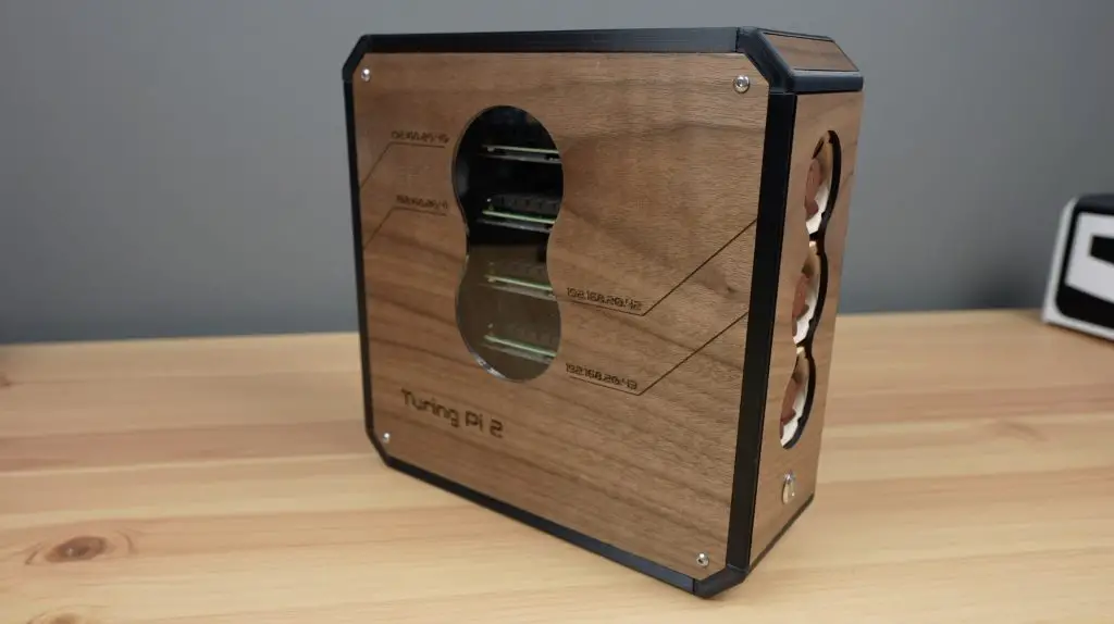
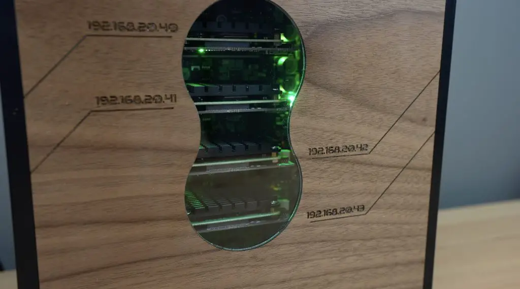
I’d like the side panel to still have some visibility into the case to see the blinking lights on the Turing Pi board – so I’ve added a small cutout on the side to match the design of the fan cutout on the front.
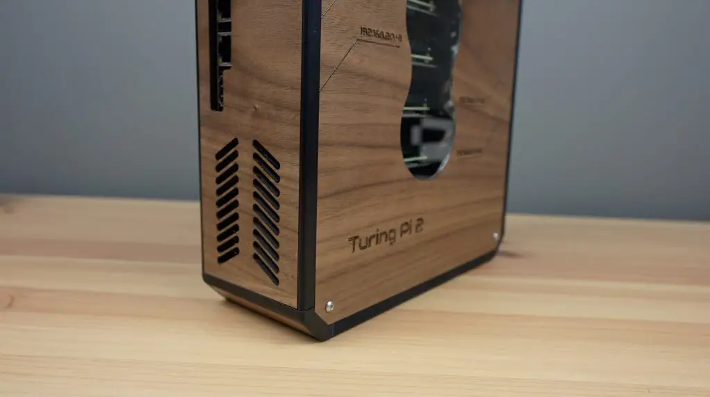
I’ve then also added ventilation holes and ports to the back and top panels.
That’s the design done, so let’s now move on to making up the parts.
Unboxing & Setting Up The Creality Falcon 2 40W
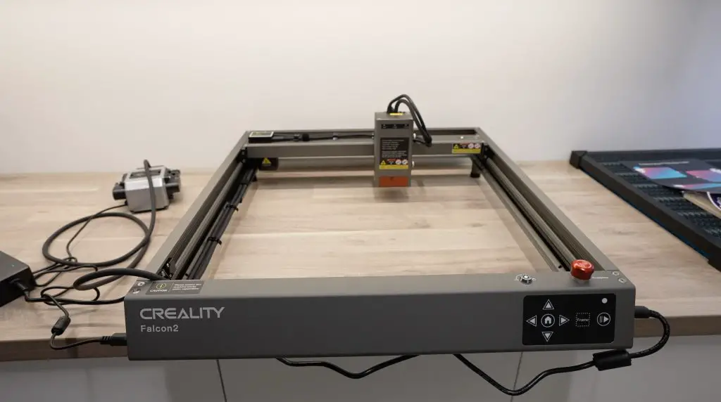
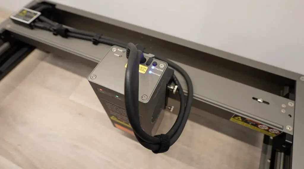
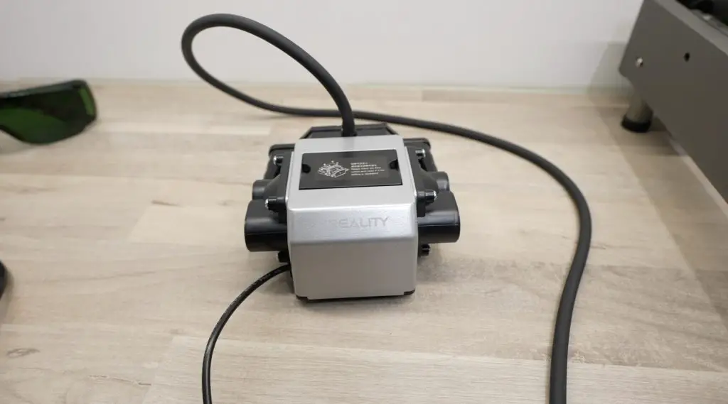
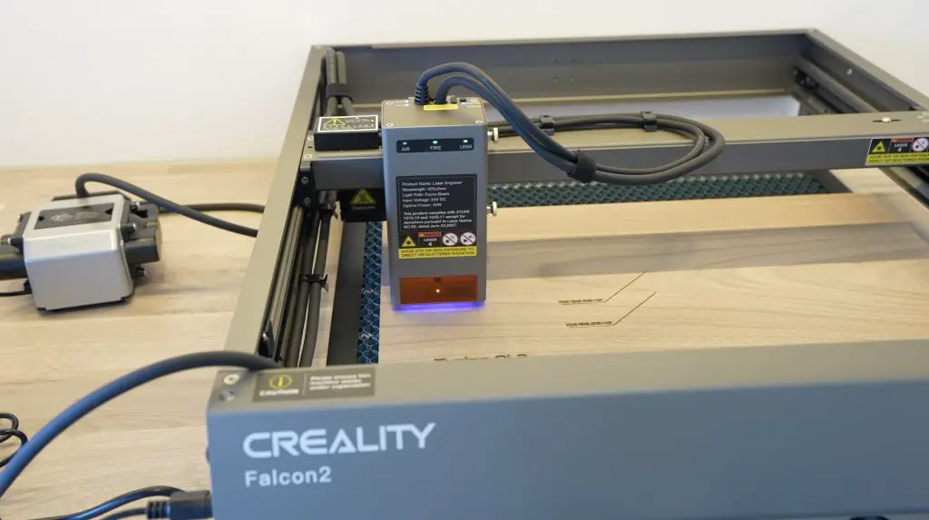
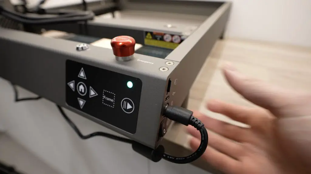
To make up the walnut panels, I’m going to be using the new Falcon 2 40W laser cutter and engraver from Creality.
This is an open gantry-style laser with a new powerful 40W diode laser module. It’s also got some interesting features that differentiate it from other similarly powered lasers which we’ll take a look at while using it.
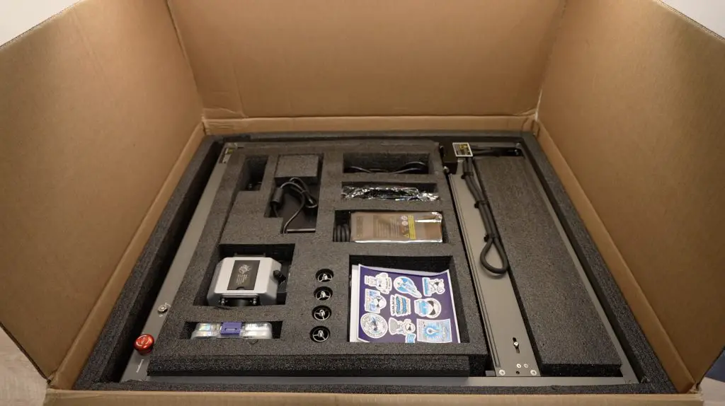
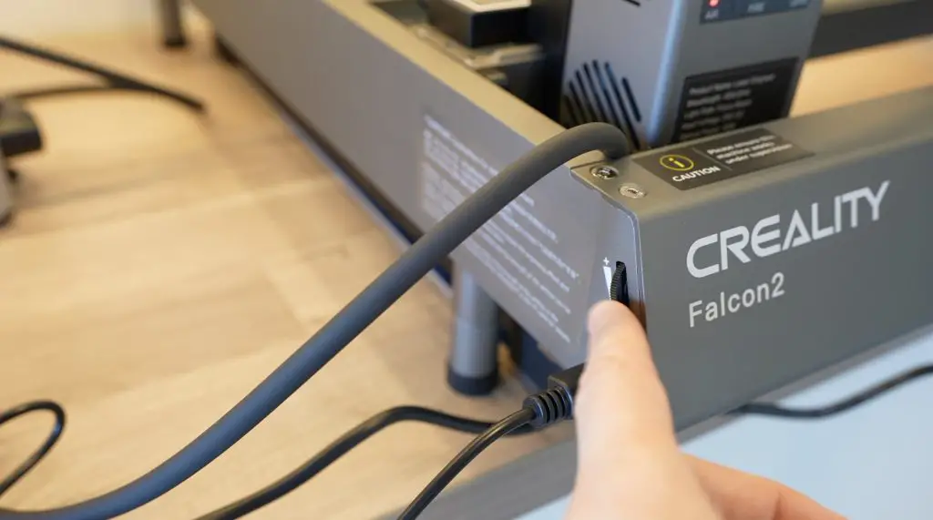
It comes with a pre-assembled frame, so it is almost ready to run when you take it out of the box. This is the first gantry-style laser that I’ve seen that comes like this, most of them require a bit of assembly.
Note – the honeycomb bed used below is sold separately and is not included with the Falcon 2 40W.
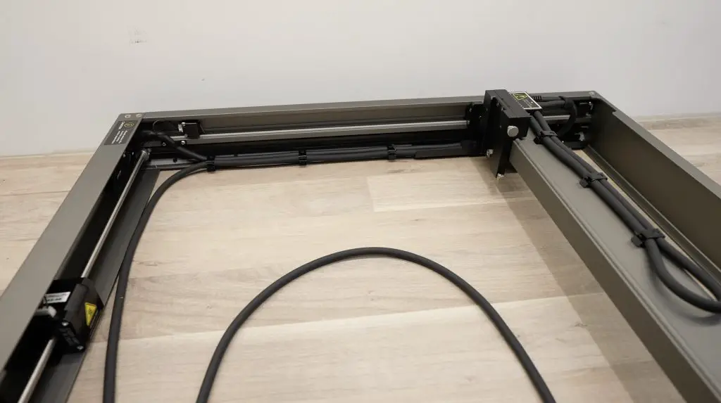
The frame is also a full custom aluminium design and isn’t made up of sections of v-slot extrusion. This looks a bit more modern and professional. It also hides the motors and provides well-thought-out cable management.
They’ve got good finishing touches on it too, like moveable and extendable feet which give you more flexibility on your work surface and with what materials you are able to use with it.
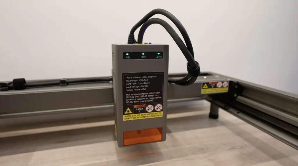
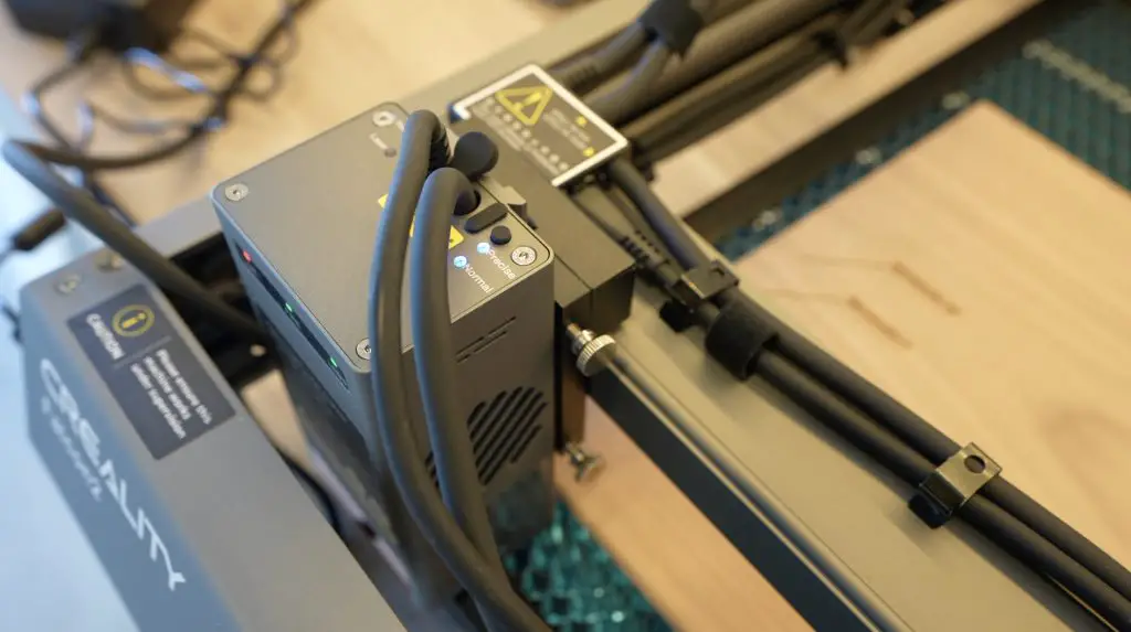
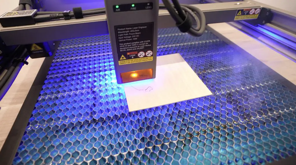
One of the unique features of the Falcon 2 40W is the adjustable laser beam. If you’re familiar with diode lasers then you may know that these more powerful modules are made by combining the light from multiple smaller laser diodes – this one actually has 8 diodes.
This results in a more powerful laser beam but the drawback is that this also increases the laser spot size, meaning more material is cut away with each pass and you get slightly reduced resolution when engraving. The Falcon 2 40W accounts for this by allowing two modes, normal mode, which is the more powerful mode with a larger spot size, and then precise mode which has less power but has a smaller spot size. So in my design, I’m going to do some engraving on the large main panel so that I make use of both of these modes.
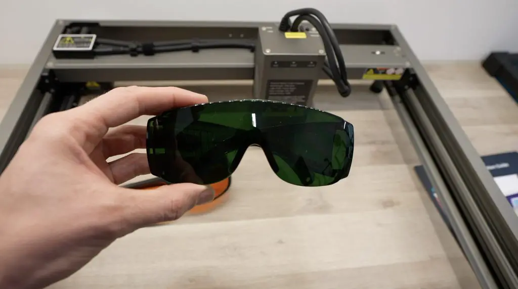
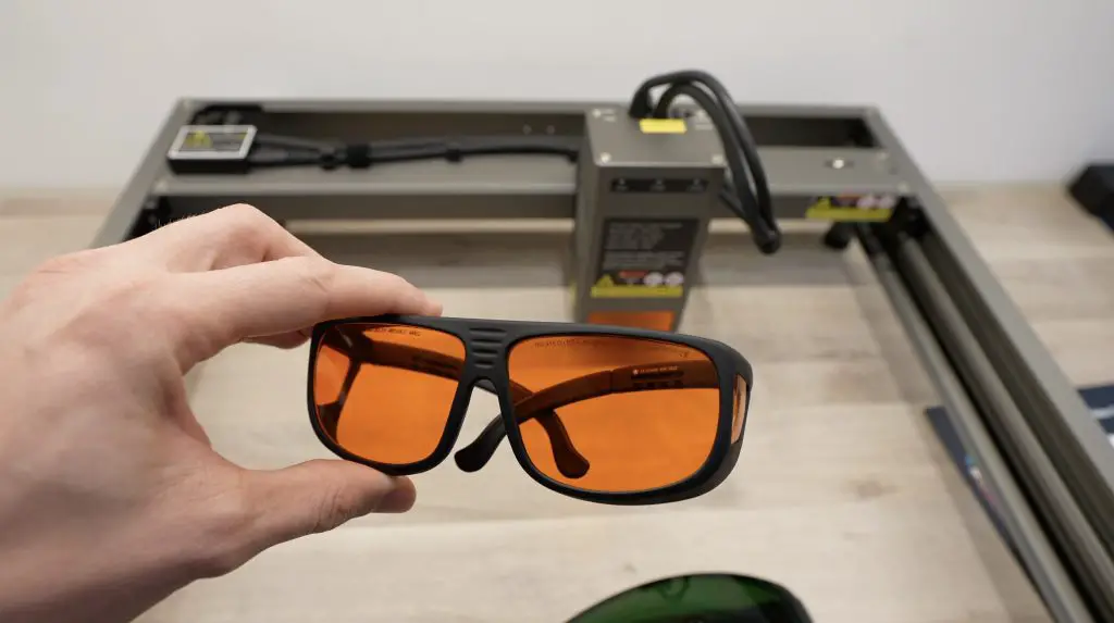
As far as Safety goes, the Falcon 2 has a couple of integrated safety features. The kit comes with a pair of safety glasses, but I always suggest that you get a proper set of certified safety glasses if you’re going to be working with an open-style laser like this. Better yet, fully enclose it.
The Falcon 2 also has airflow monitoring, lens monitoring and flame monitoring. It will also stop if it is bumped or tilted, has an e-stop on the controller and has limit switches on all travel limits.
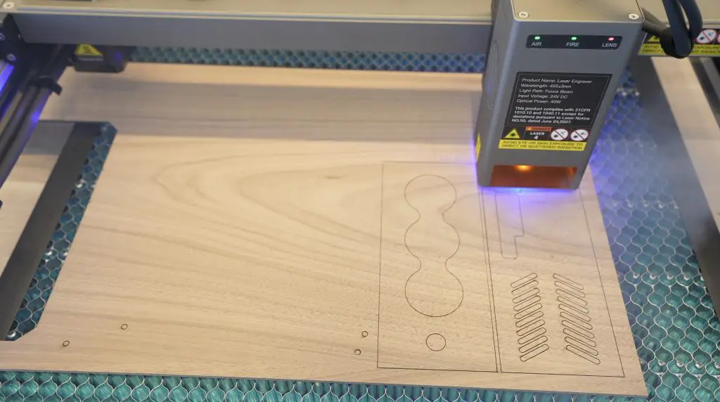
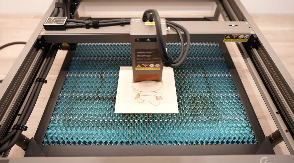
Laser Cutting & Engraving The Walnut Panels
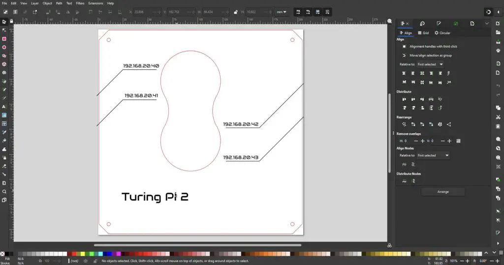
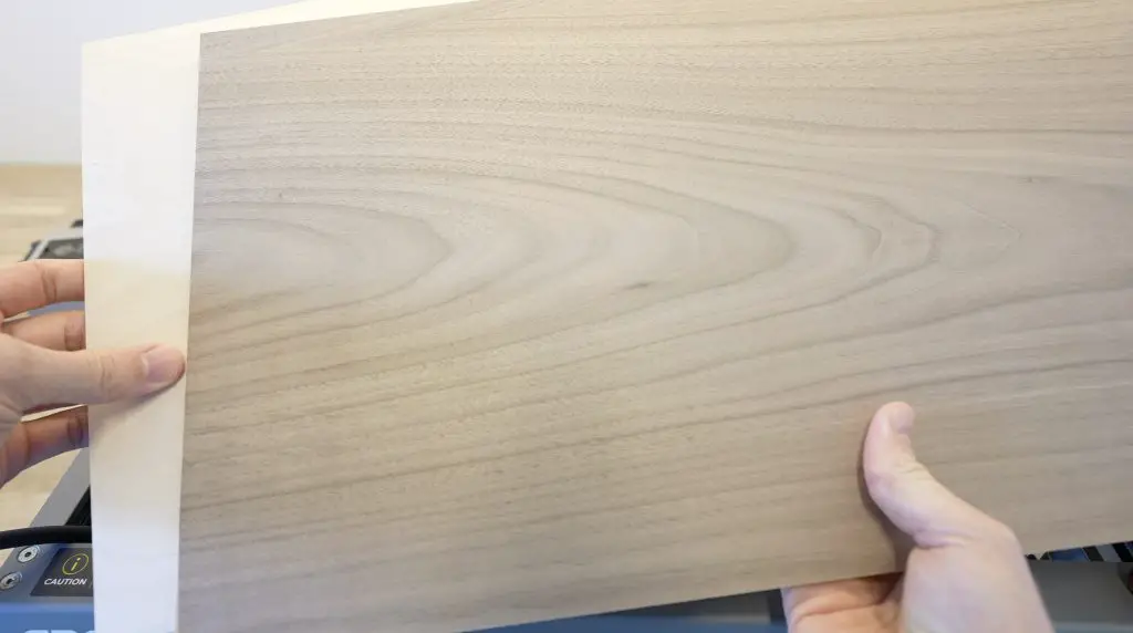
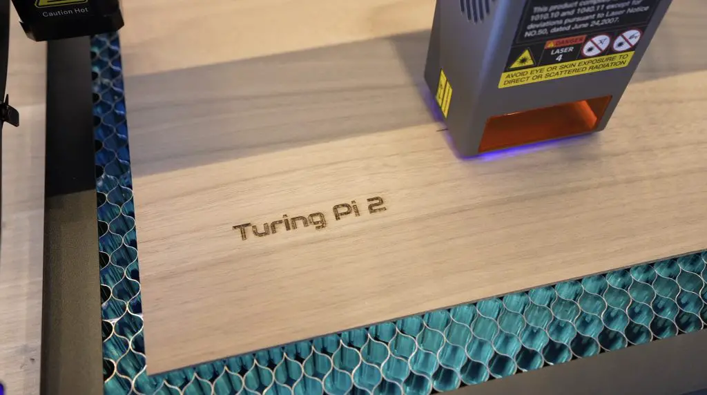
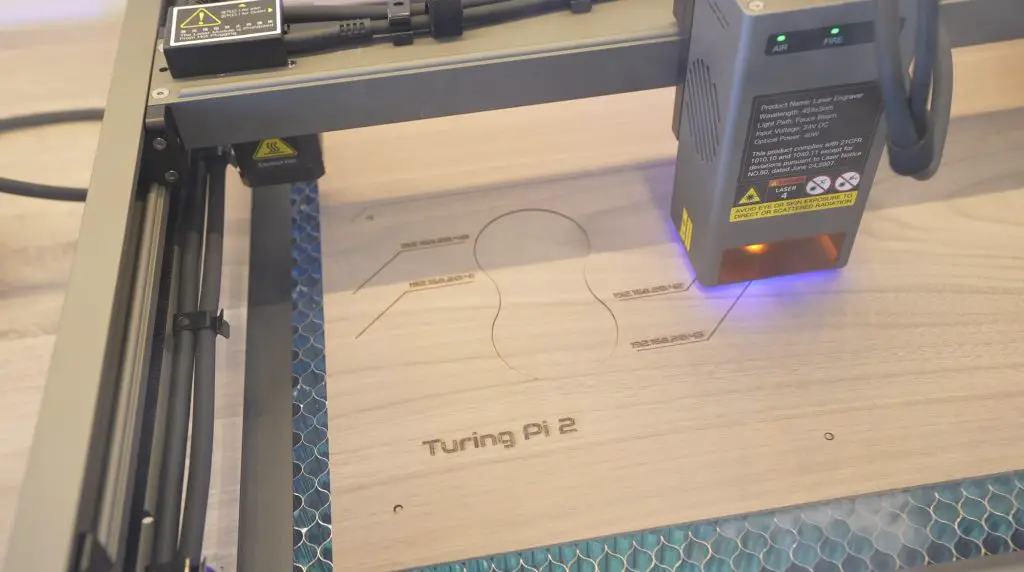
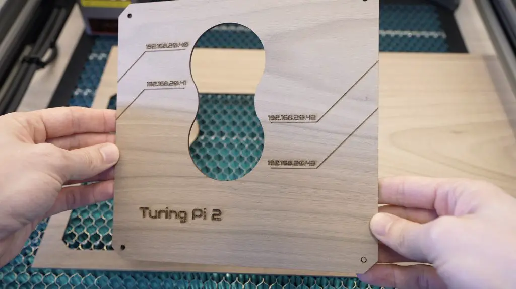
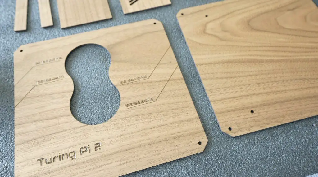
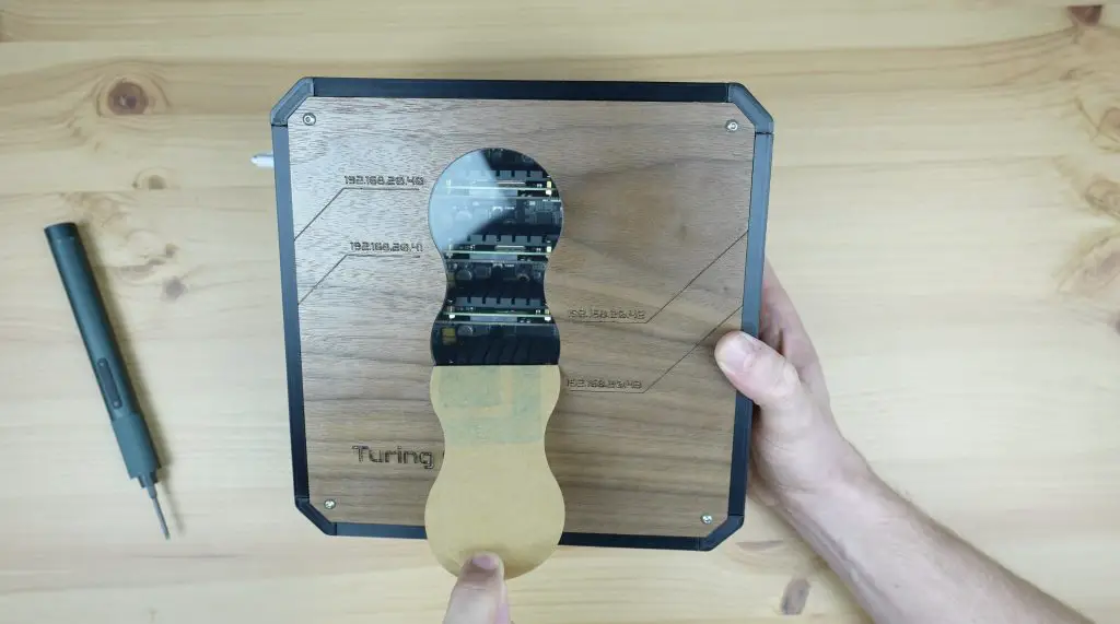
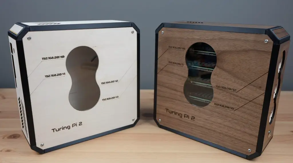
Before we start cutting the plywood panels, we need to add the engraving detail. To do this, I opened the main side panel in Inkscape. I’ve added the Turing Pi 2 name at the bottom and a design to label each of the four nodes by their assigned IP address.
I’m going to be using a walnut finish plywood, which I’ll varnish at the end for a rich satin colour to contrast the black 3D-printed parts.
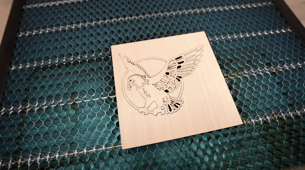
Let’s engrave and cut the large main panel first.
In normal mode, they claim that you can cut up to 20mm wood, 30mm black acrylic and up to 0.15mm stainless steel sheets each in a single pass. This is only 3mm walnut plywood, which is a slightly harder wood than regular plywood but shouldn’t be any trouble for the 40W laser even at a bit of speed.
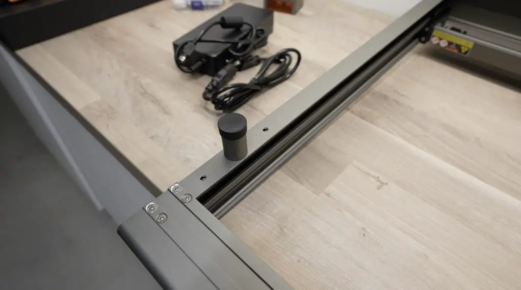
The Falcon 2 also includes an integrated air assist system that uses an external compressor to supply air through to a nozzle around the laser head for much cleaner cuts and to keep the lens clean.
We’ll start off with the engraving first. To do this, we’ll turn off the air assist and then set the laser to precise mode to engrave the text and line details.
Next let’s turn the air assist back on and set the laser back to normal to cut the panel and centre window out.
As with all of these open gantry-style lasers, they produce a lot of smoke when cuttings. So it would be best to work in a well-ventilated area or to get an enclosure for it.
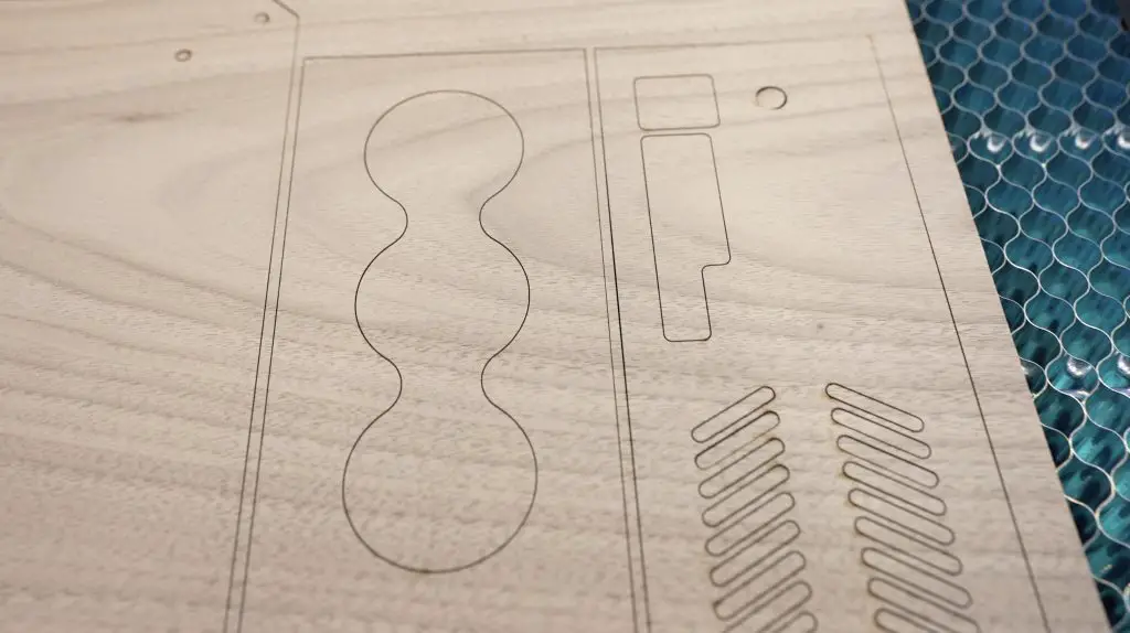
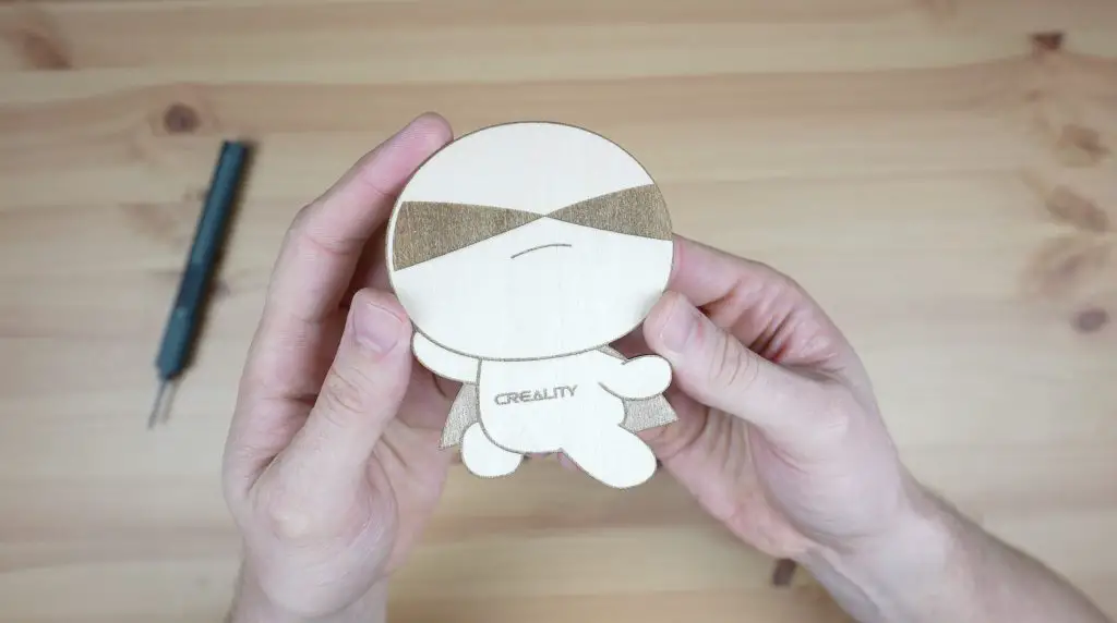
The first panel has come out really well. I’m starting to get excited to see how these panels fit in with the 3D-printed parts and come together to form a complete case.
Next, let’s cut the remaining panels and corner filler pieces.
These have also come out really well. The cut quality is impressively clean with the integrated air assist system.
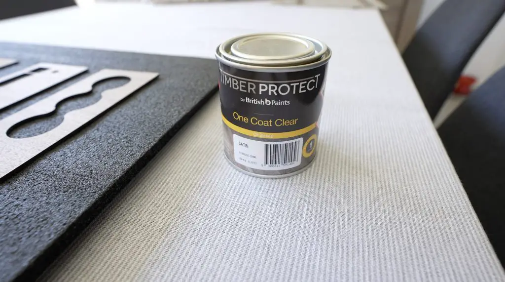
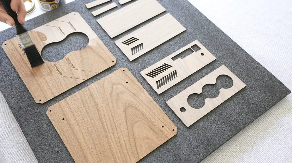
Now we can finish them off with a coat of satin varnish. I don’t want them to be glossy so I prefer a satin or matt finish. Varnish helps to bring out the natural colour of the wood and to protect it from dirt and fingerprints.
Making Up The 3D Printed Frame Components
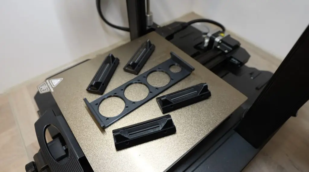
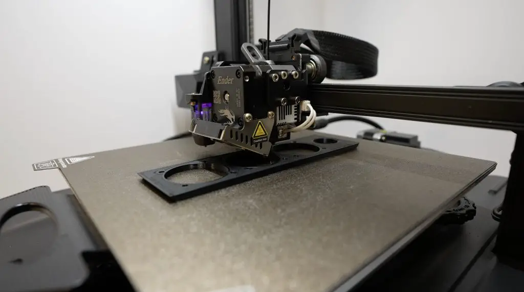
To make up the frame, I started by 3D printing the frame components on my Creality Ender 3 S1 Pro. I need four corner pieces and four side panels – they’re all the same so it’s easy to print on repeat or to fill the bed with them. To hold the three fans in front in place, we also need to print a fan holder.
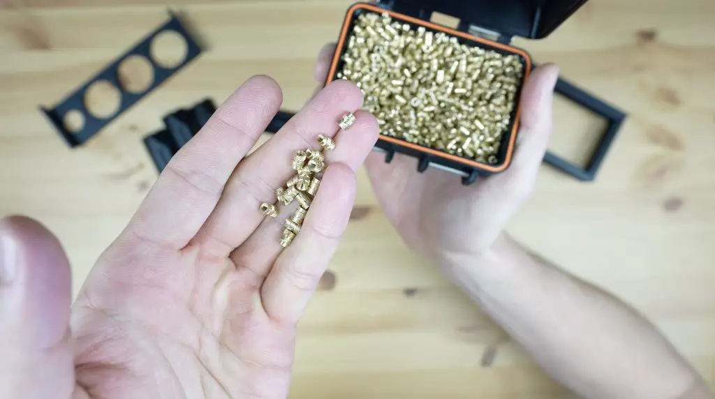
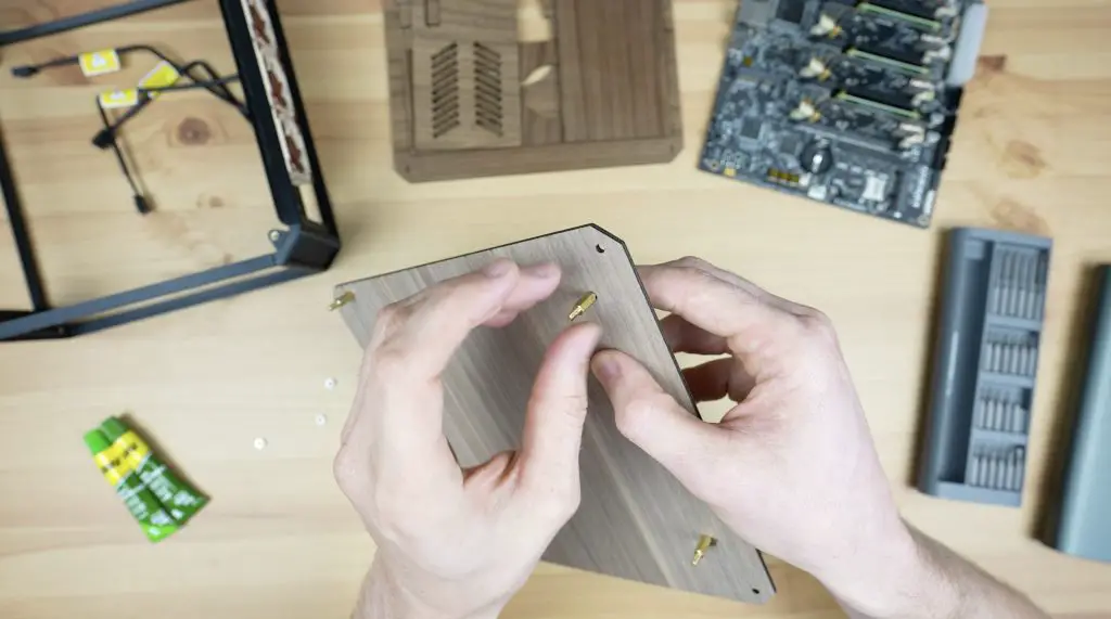
The 3D-printed parts need a little bit more work before they’re ready to assemble. I have already removed the supports on the corner pieces, but now we need to add some brass inserts to them for them to screw together.
I’m using two different brass insert sizes. Each corner has four M2.5 inserts to hold the adjacent side pieces in place and two M3 inserts that will hold the main plywood panels in place.
These inserts are just melted into the corner piece using a soldering iron with a brass insert tooltip. We need to be a little careful with the M2.5 ones as they need to go in at a 45-degree angle.
Now that we’ve got the pieces all made up, let’s put the frame together.
Assembling The Mini ITX Case
Each 3D printed side is held in place on the adjacent corner pieces with four M2.5 screws, two on each side. These are all M2.5x6mm screws except in the front where we’ll use 12mm screws to go through the fan holder as well.
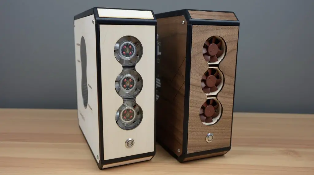
Before we screw the fan holder into place, let’s mount the three fans onto it. I’m using 40mm 5V Noctua fans that are each 10mm thick. I choose Noctua fans because they’re quiet and because I think that the colour scheme will fit in well with the walnut panels. We need to use M3 screws and nuts to hold them in place so that the heads of the screws are almost flush with the top of the fans. This allows the front plywood panel to sit really close to the surface of the fan.
Then we can mount the fan holder and side piece in place to complete the case frame.
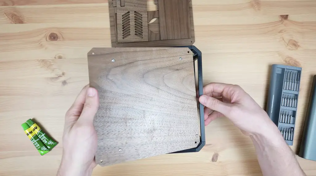
Now let’s move on to mounting the Turing Pi and plywood panels.
You’ll notice that I don’t have any screw holes on the smaller plywood panels to hold them in place. I didn’t want to have a case with a large number of screws visible, so these are all going to be held in place with epoxy. The two main panels will still be removable with screws to allow easy access into the case and to remove the Turing Pi 2.
Next, let’s mount the Turing Pi 2 onto the back main panel. I’m going to do this with some M3x10mm brass standoffs which are held in place with M3x8mm button head screws on the back. The board is then held in position with some M3 nuts on the threaded ends of the standoffs.
Each main panel is held in place on the frame with four M3x8mm button head screws.
To keep the case a bit more closed up and protected, I’m going to add a clear acrylic insert into the cutout. Being a diode laser, the Falcon 2 can’t cut clear acrylic, but an alternative would be to just stick a 1-2mm thick square of acrylic onto the inside of the plywood panel where it won’t be visible and will still close up the cutout.
We can then epoxy the side panels into place. I’ve intentionally added the main panels first because there is some flexibility in the 3D-printed parts. The main panels help to square up the whole frame beforehand so that we’re not glueing panels into place on a twisted frame.
Lastly, we can epoxy the corner filler pieces into place.
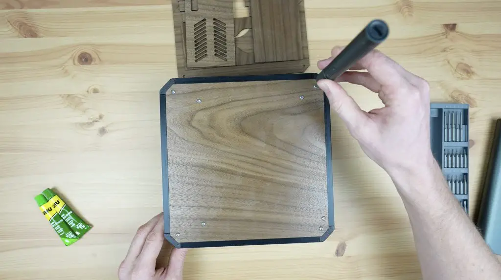
Now we just need to add the power supply module and its power port, connect the fans up, which I’m doing with a wiring harness I made up, and add the power button to the front panel.
We can close up the side panel and peel off the protective film.
And that’s the case complete.
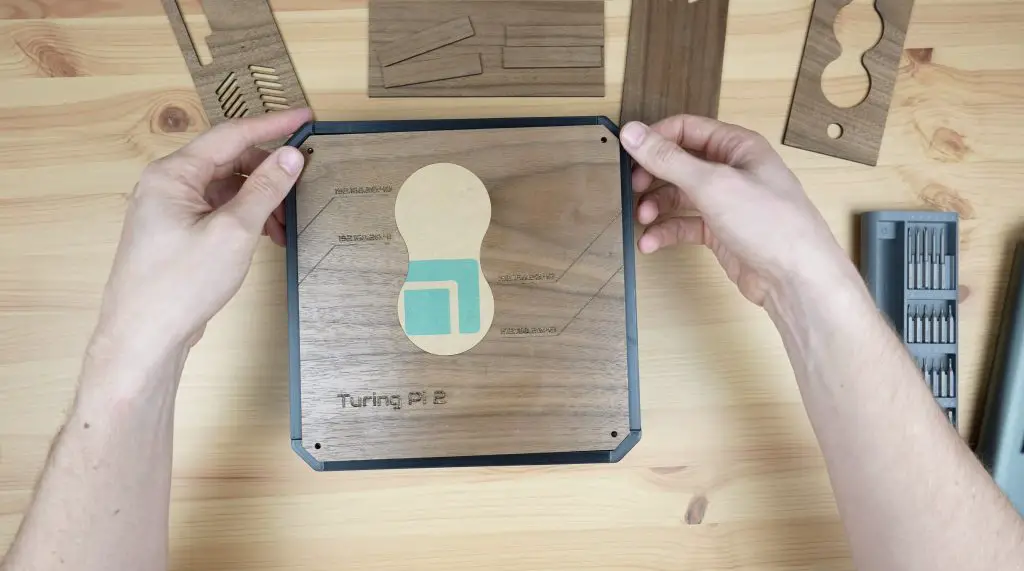
Different Colour Options For The Mini ITX Case
You obviously don’t have to use black for the 3D prints or walnut plywood for the panels. By using different filament and wood colours, there are unlimited design possibilities.
Let me know which of these two designs you prefer in the comments section below.
Final Thoughts On The Falcon 2 40W
The Falcon 2 also supports offline control (control without a connected computer) but this is a bit different to some other lasers that come with a display. This offline control just loads the most recent gcode file in the root directory of the microSD card.
It gives you a way to cut or engrave directly from the microSD card, but it is somewhat limited. You’ll still need to regularly use a computer to change files around on the microSD card if you don’t just cut the same file repeatedly.
That said, I did manage to use it to cut this included design out.
If you don’t yet have a laser cutter and engraver, the Falcon 2 is a great all-rounder that has the power to cut thicker materials but can still retain the detail in engraving finer artwork and text as well.
I use a laser in my workshop far more often than I ever thought I would. With a laser, I can make up the parts to build a model or enclosure in a few minutes, whereas similar parts would have taken hours to 3D print.
The Creality Falcon 2 looks modern and is a good quality, sturdy build.
If you’d like to get your own Creality Falcon 2 40W, they’re available from $1,699 through their web store. With Creality, you’re also buying from a company that has a great track record in quality and support with their 3D printers.
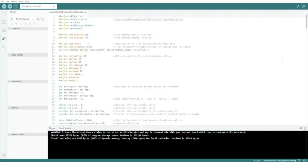
Today we’re going to be using the new Arduino Uno R4 WiFi to build a controller for a PET bottle recycler. I’m doing this as the first part of a project, working towards building my own version of a PET bottle recycler to produce filament for my 3D printer. I already have an idea of what I want the machine to look like mechanically, so for Part 1 I’m going to focus on building the electronics to provide temperature control of the 3D printer hot-end and to drive the extruder motor.
I have now completed the PET Bottle Recycler, you can find Part 2 here.
Here’s my video of the build, read on for the written guide;
Some of the above parts are affiliate links. By purchasing products through the above links, you’ll be supporting my blog, at no additional cost to you.
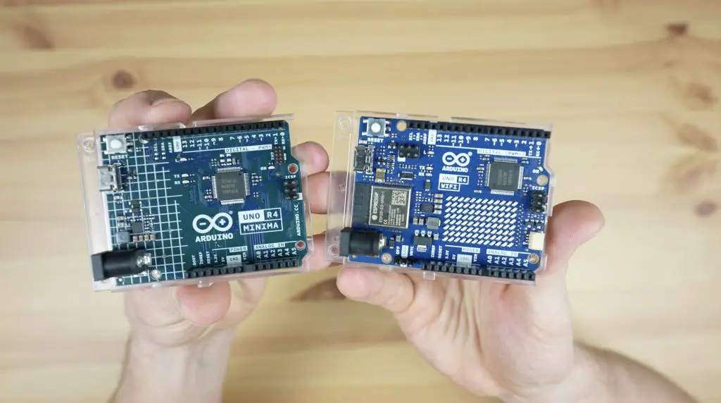
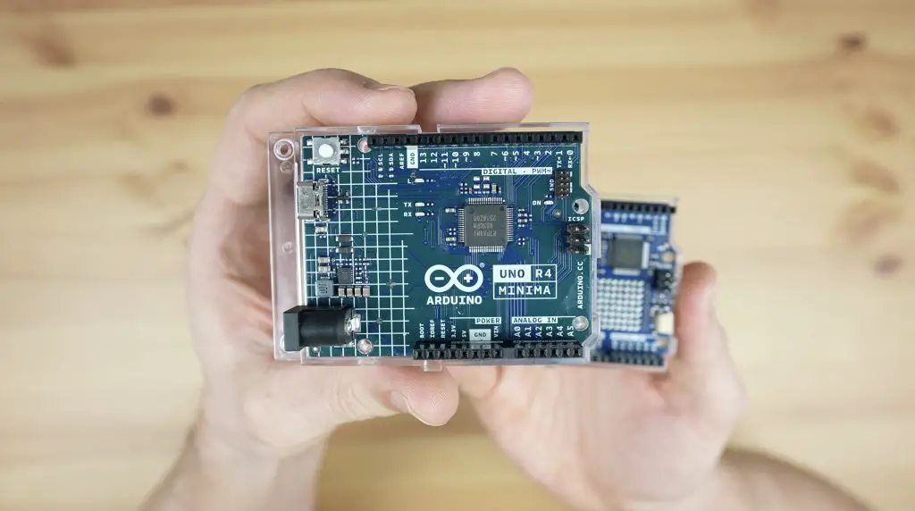
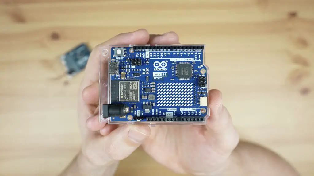
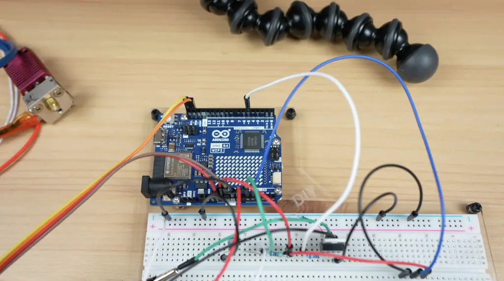
Arduino Uno R4 Minima & WiFi
I’m going to start the project by using an Arduino Uno R4 for prototyping. The Uno 4 comes in two versions, the minima which is the more basic version and then the WiFi version which has WiFi and an integrated LED matrix.
They both have a new more powerful 32-bit processor as well as significantly increased SRAM and flash memory, allowing you to build more complex projects.
The LED matrix on the WiFi board is really useful for quickly displaying a status or mode, and you can even run some animations and games on it.
For prototyping, I’m going to use it as a rolling graph of the hot-end temperature so that we can see how it is tracking towards the setpoint.
Recycler Controller Components
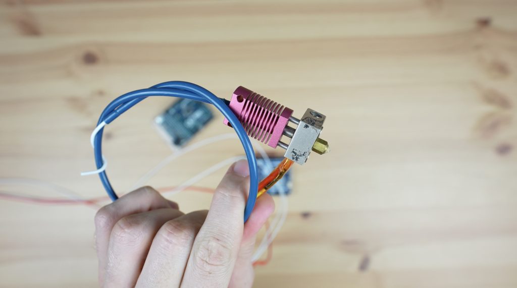
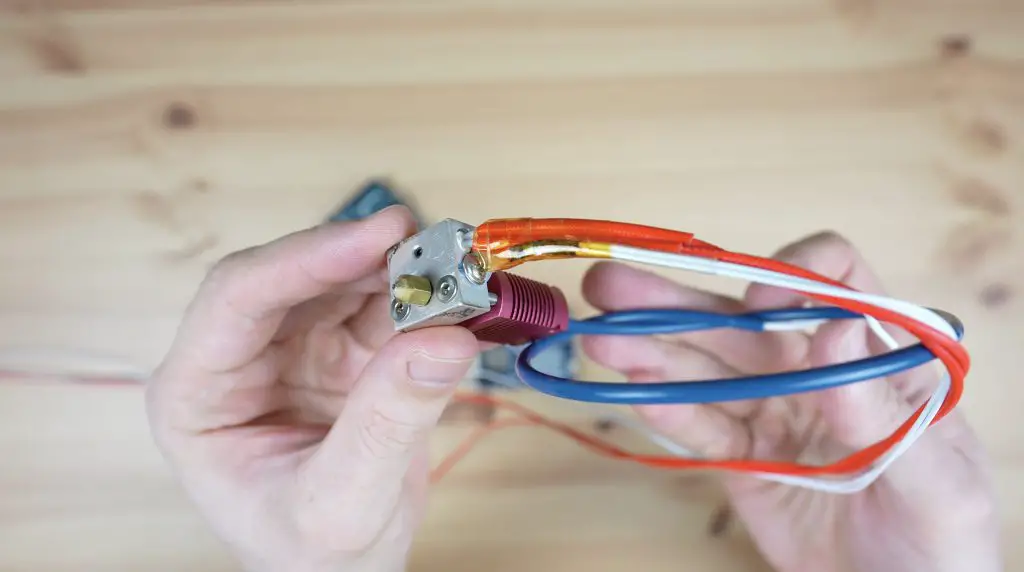
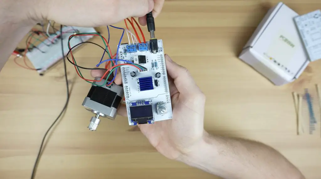
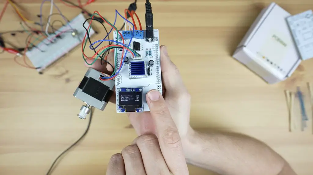
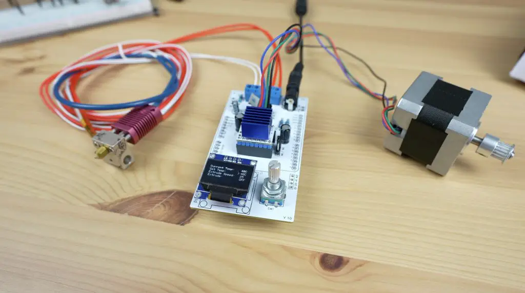
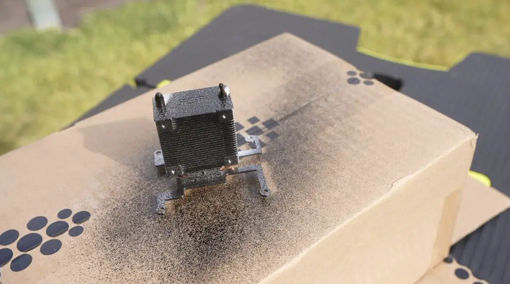
To turn a PET bottle (a standard soda bottle, like Pepsi, Coke or Mountain Dew) into filament, we need a way to melt the plastic. To do that, I’m going to be using a hot-end from an old 3D printer. This one is from an old Creality Ender 3 Pro.
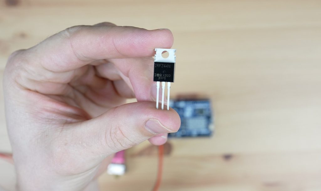
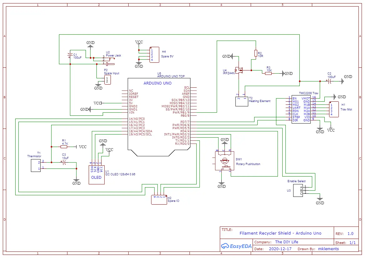
An Arduino obviously can’t pass through enough power to heat the hot end by itself, so for that we’re going to be using an IRFZ44N Power MOSFET.
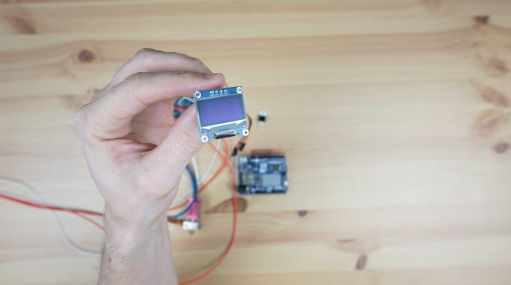
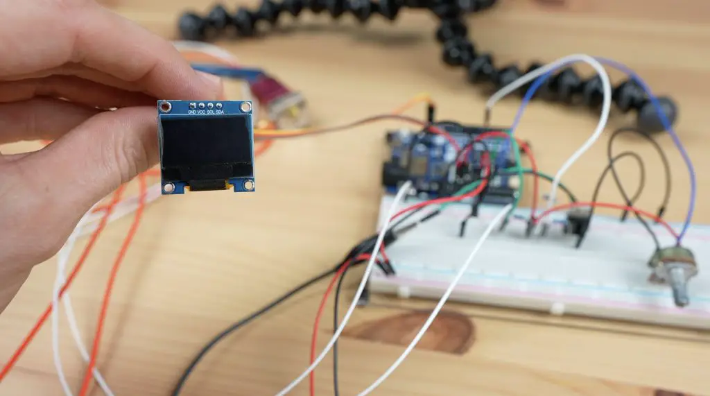
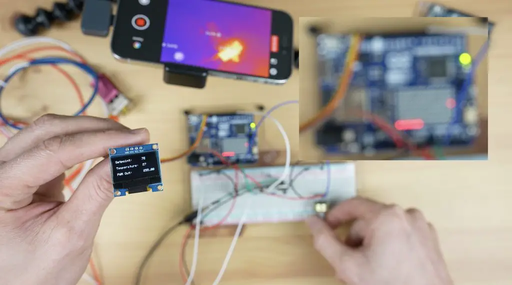
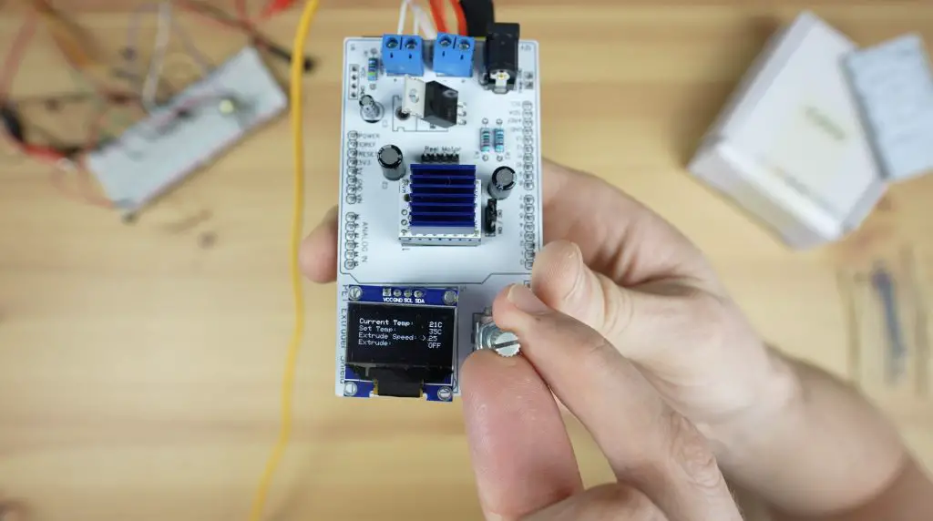
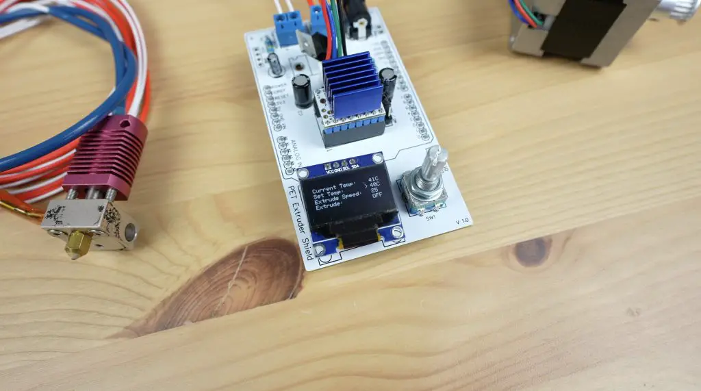
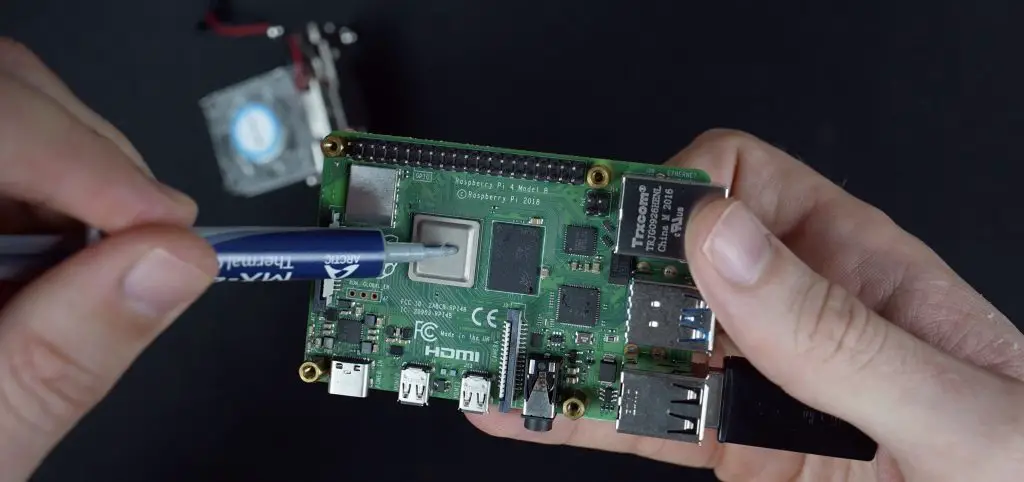
This will take a PWM signal from the Arduino and use it to control the power supplied through to the hot end so that we can maintain a set temperature. I’m also going to add an I2C OLED display to display the exact temperature and allow us to make changes to the temperature and the extruder motor speed.
A temperature sensing element, or thermistor, is also built into the hot end and we’ll use the signal from this to tell the Arduino what the actual temperature of the hot end is so that it knows whether to turn the heating element on or off.
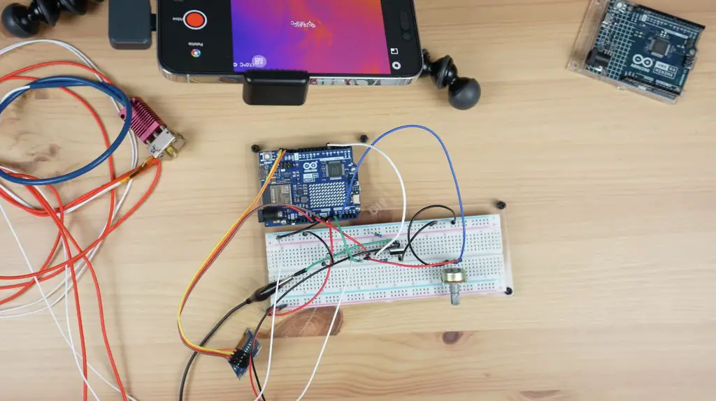
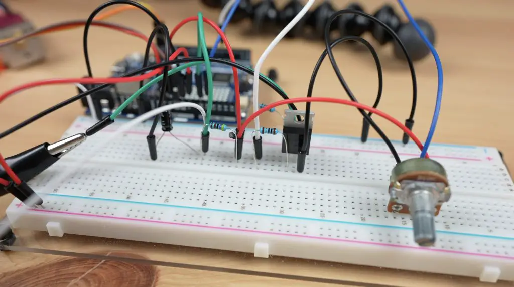
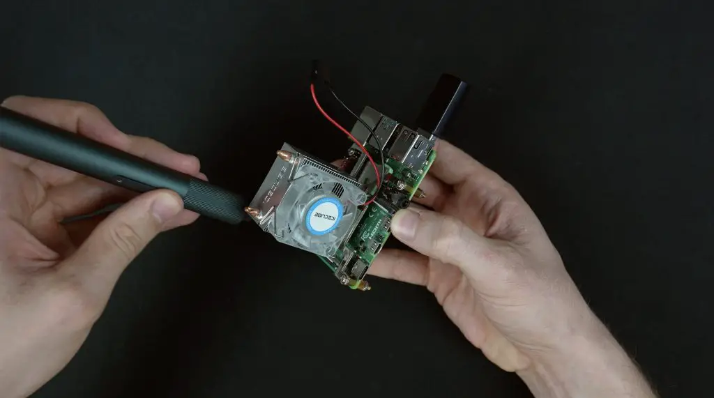
Breadboard Test Circuit
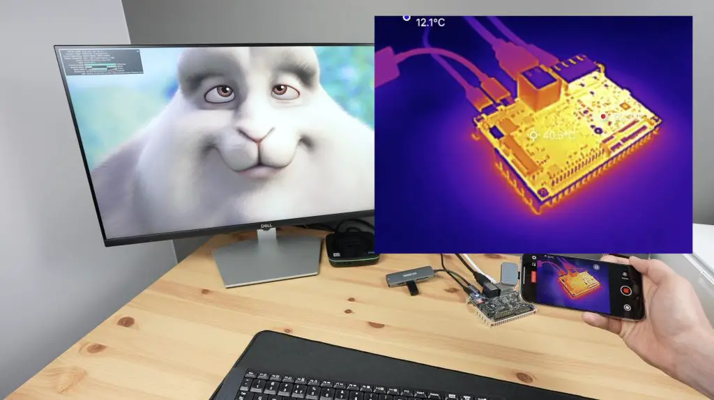
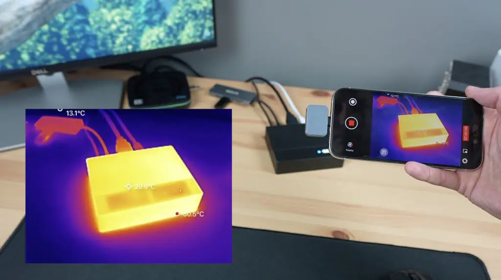
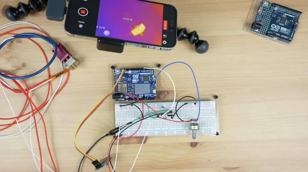
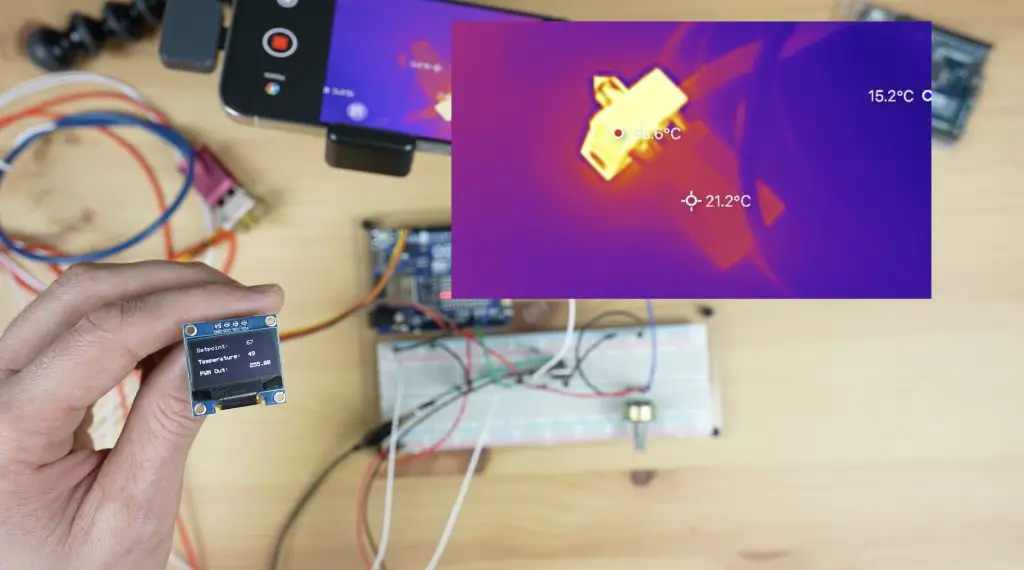
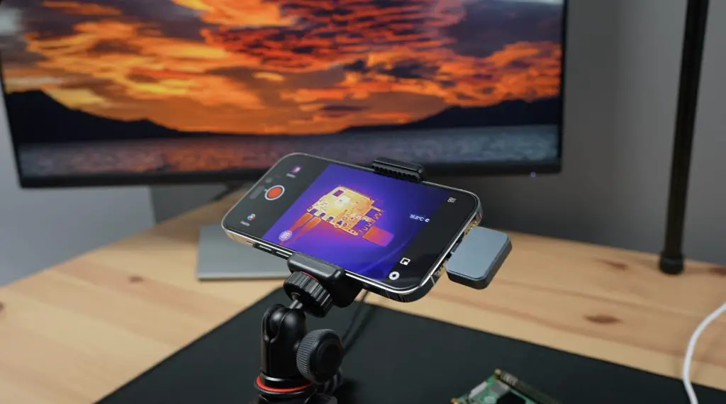
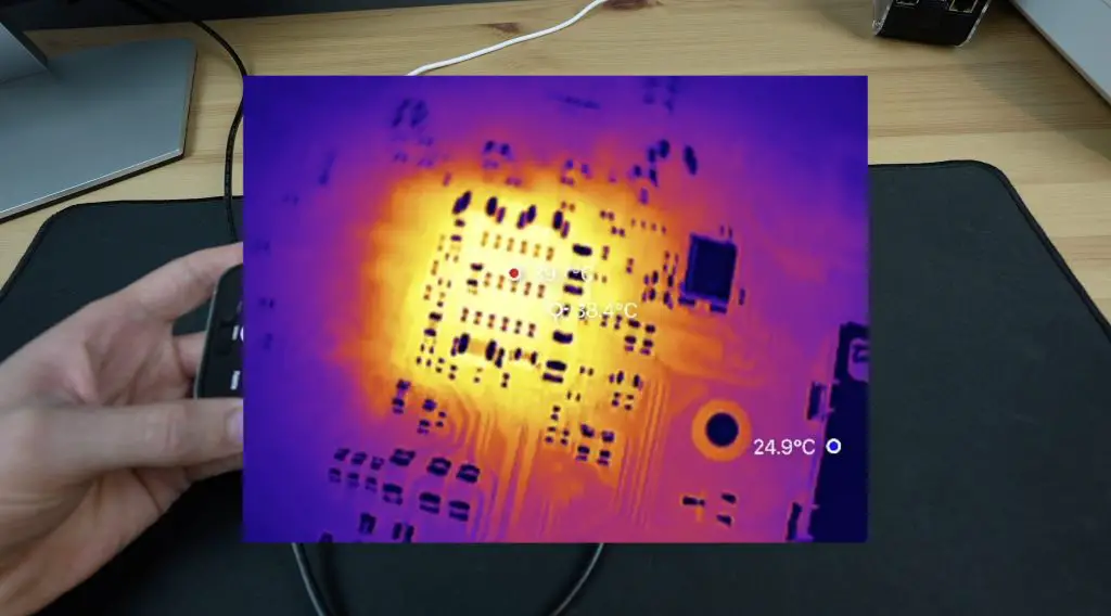
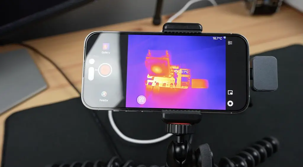
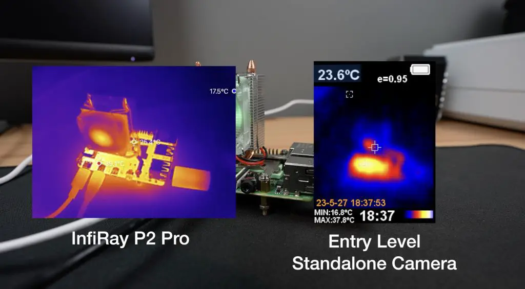
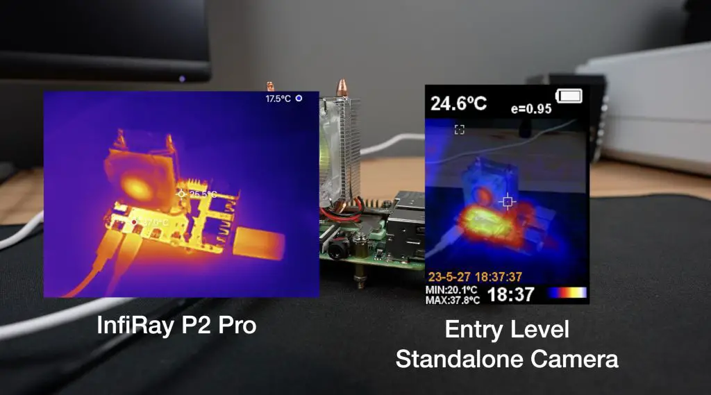
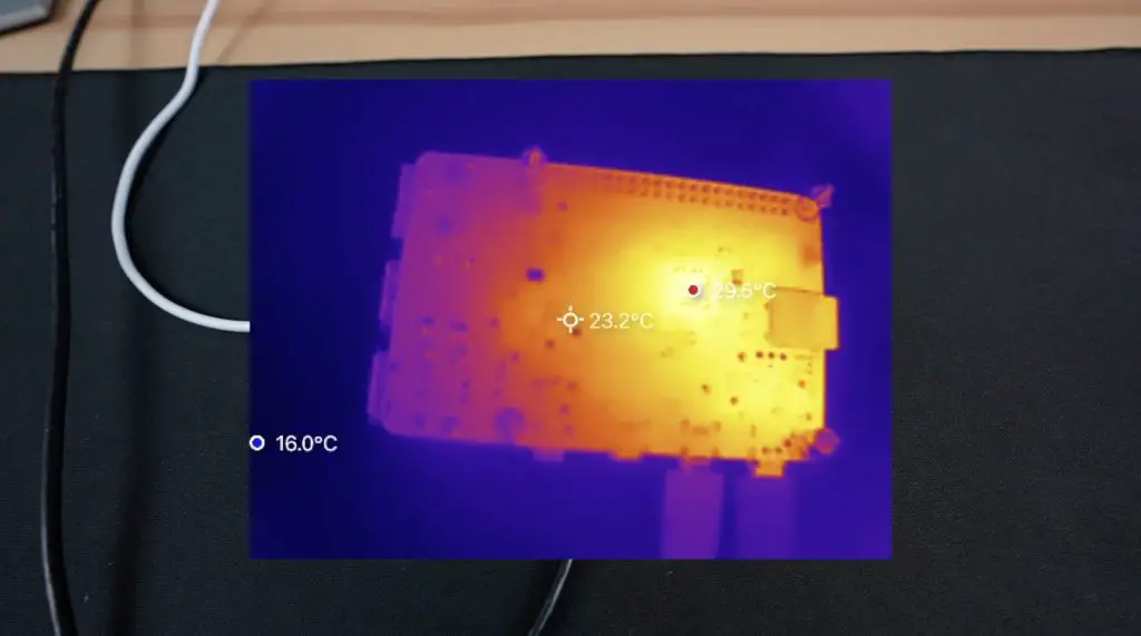
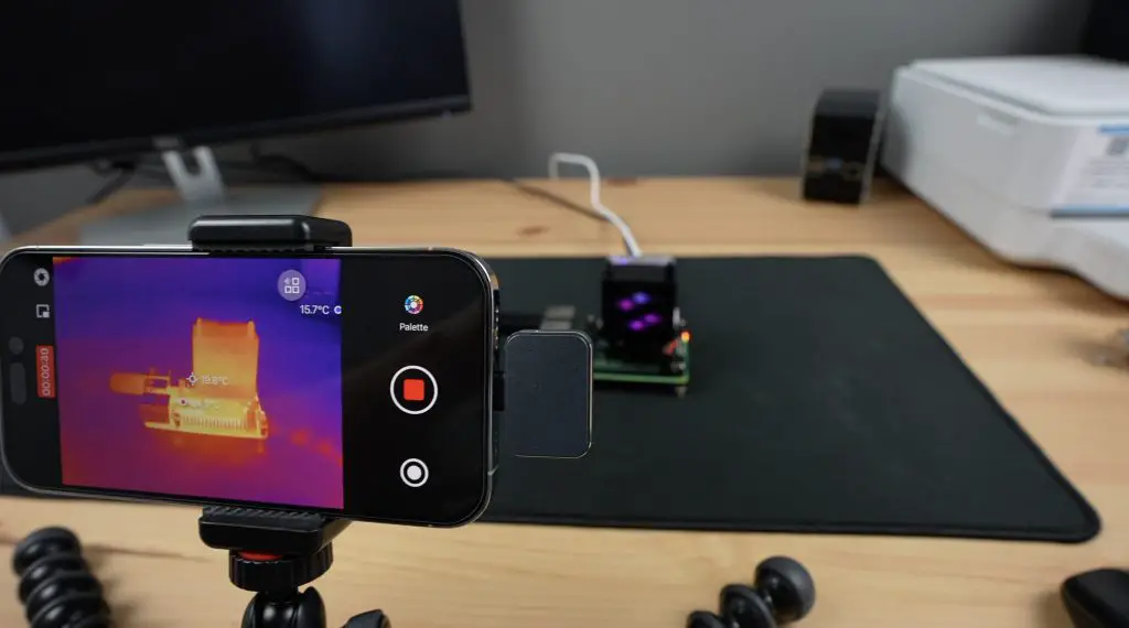
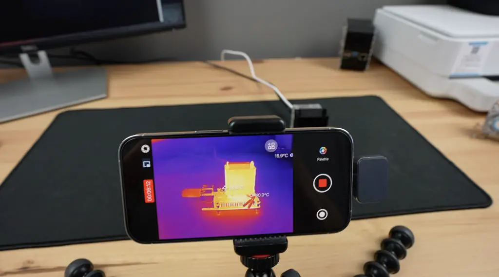
As a starting point, I have made up the basic circuit on a breadboard to test that we’re actually able to control the hot end. I’ve also set up a thermal camera to watch the hot end so that we can visualise it heating up.
There are two main circuits here, one with the power Mosfet and some resistors to control the heating element and a second with a capacitor and resistor to read in the temperature.
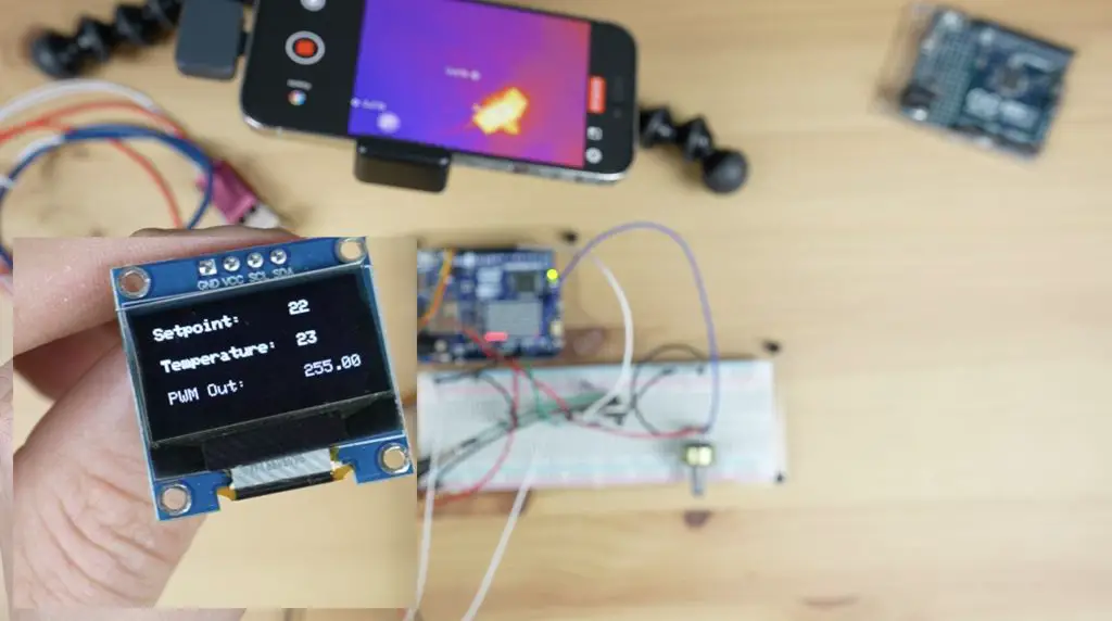
As I said earlier, I’m going to be using the LED matrix on the Arduino as a means of indicating how the temperature of the hot end is tracking towards the setpoint, but I’ve also added an I2C OLED display which will give us an exact temperature readout, the temperature setpoint that we’re working towards and for now an indication of the PWM value being applied to the hot end.
I have also included a potentiometer to adjust the temperature setpoint between an upper and lower limit.
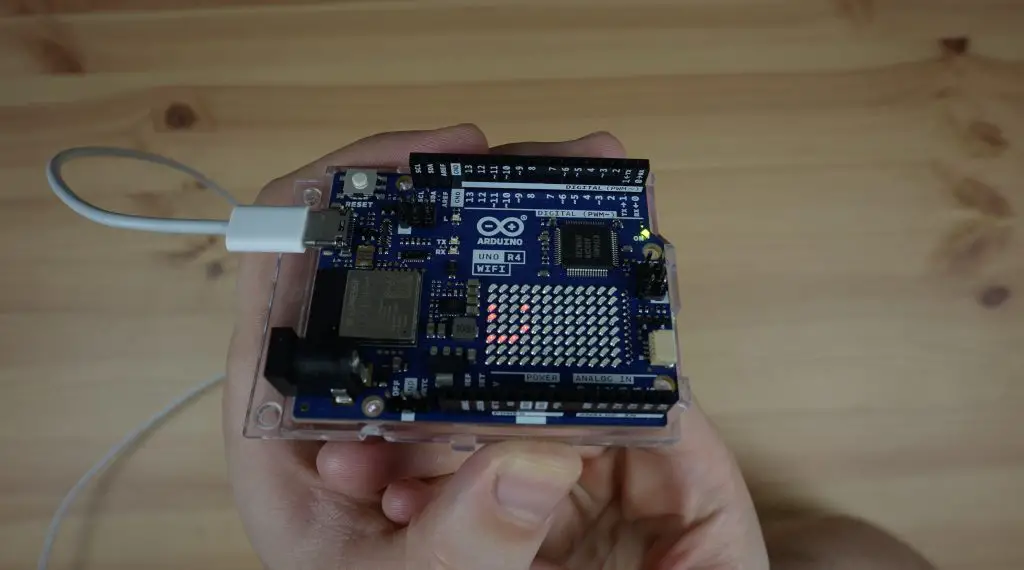
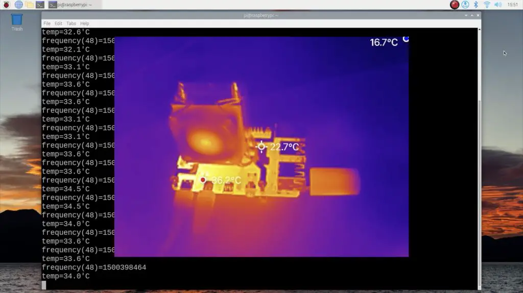
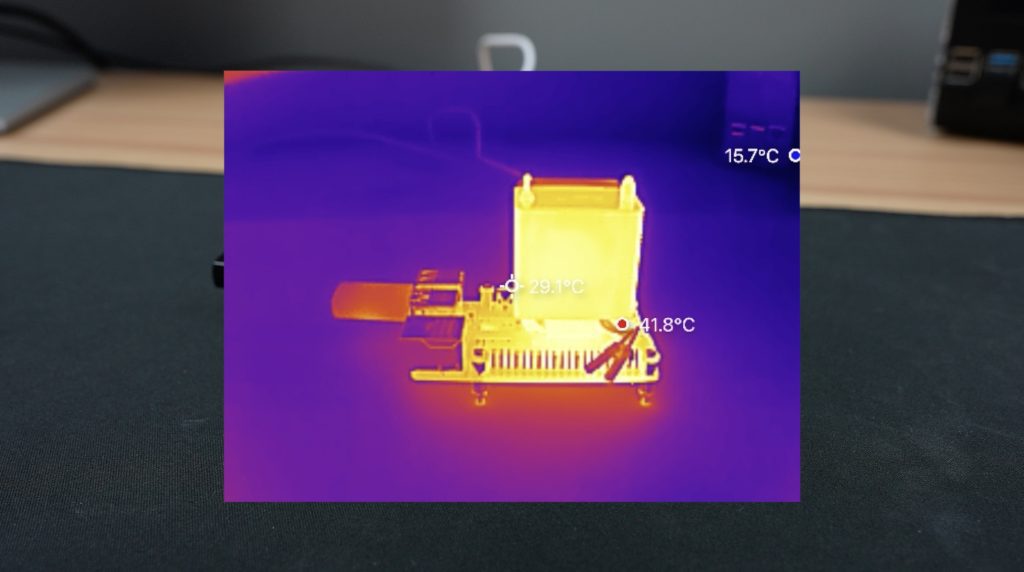
So let’s put power onto the circuit and we’ll hopefully be able to see how it heats up on the thermal camera. After about 30 seconds, we can already see the hot end head heating up.
I’ve used the last column of the LED matrix on the Arduino to indicate the current setpoint that the hot end is heating up to. The graph loops around, increasing as the temperature increases. It is quite slow as I’m only using a supply voltage of 12V where the hot end is rated at 24V.
On the OLED display, we can see the temperature setpoint, the current temperature and then the PWM output to the hot end. This stays at the maximum of while heating up and then as the temperature approaches the setpoint, it starts tapering off.
I’m using a PID control function to control the temperature of the hot end, so I’ve tuned the proportional, integral and derivative gain values to provide reasonably good tracking of the setpoint.
After a minute or so, we can now see that the hot end has heated up on the thermal camera.
Now that we’ve got the system working on the breadboard, let’s turn it into something a bit more permanent and reliable for the project.
Designing The Recycler Controller PCB
I drew up a schematic and designed a PCB for the recycler controller in the form of a shield to fit on top of the Arduino.
This shield has the heating element circuit, the thermistor circuit and a TMC2208 stepper motor driver to drive the extruder. It’s also got an I2C OLED display and a rotary pushbutton to make changes to the settings.
PCBWay then made them up for me. They have a really easy-to-use one-page order form to upload your files to and choose from a range of manufacturing options, with defaults preselected.
They’ll then make them up for you in 24hrs for just $5 for five, two-layer PCBs. They also offer a range of shipping options to fit your timing and budget. If you haven’t tried making your own PCBs for a project, I’d definitely recommend trying PCBWay out to really take your projects to the next really.
They arrive a few days later, I choose a white PCB with a black silkscreen, just because I haven’t tried this colour scheme before.
The PCB is designed to interface with the Arduino through some header pins which we’ll add to the underside.
Now we just need to get the components soldered onto the board.
Assembling The Controller PCB
I soldered the components to the board starting with the smaller components and moving on to the larger ones.
Because this first one is still a prototype board, I’m going to solder some female header strips onto the stepper motor driver and display pads so that I can remove the display and driver to use on the final board. I also soldered the header pins for the Arduino into place while plugged into the Arduino as this keeps them lined up properly.
And with the soldering done, it’s time for the moment of truth – to see if my board design and soldering is good. I plugged in the motor driver, jumper and display. I then screwed the heating element and thermistor into the terminals and plugged it in for programming.
Programming The Arduino Uno R4
I’ve put the sketch up in my Github repository. It’s just a simple Arduino sketch that runs a PID control loop to control the temperature of the hot end and pulses the stepper motor driver to control the motor. There is also some supporting code to drive the display and manage the input from the rotary push button.
Now let’s get it uploaded to the board and see how it works.
Testing The PET Recycler Controller
The board will run on the USB power from the computer, but won’t drive the motor or heat up the element, we need to add a 12V supply to the shield’s input to power those, so let’s get that plugged in.
And now the board is running. The actual temperature is shown in the first line and we can adjust the temperature setpoint using the rotary pushbutton.
The line below allows us to change the motor speed on the extruder and the bottom line lets us turn the extruder motor on, either running forward or in reverse. Once again I’m really impressed with how quiet the TMC2208 stepper motor driver is.
I’m really happy with how this has come out. For the final version, I might try and make the PCB a bit more compact, perhaps using a smaller form factor Arduino like the Pro Mini. For now, this will be great to get started building the mechanical parts for the PET bottle recycler.
If you’re interested in seeing the project progress, be sure to subscribe to my newsletter or YouTube channel. I’ve got a geared stepper motor and pulleys coming to try out and some cool ideas for a removable spool on the recycler that I can easily move across to my printer when the filament has been extruded.
I’m also really interested to see how a recycled PET version of my 3D printable Raspberry Pi case turns out. I have now completed the PET Bottle Recycler, you can find Part 2 here.
Let me know in the comments if you’ve got any suggestions for improvements that I can make to the final version which I’ll use on the recycler.
Today we’re going to be taking a look at the Orange Pi 5 Plus, a new SBC from Orange Pi based on the Rockchip RK3588 processor.
This is one of the cheapest SBCs that I’ve seen with the RK3588 processor. The base model variant with 4GB of RAM is currently only $89, which is $40 less than the 4GB Rock 5 Model B and the top end 16GB variant is $129 which is almost $60 less.
The Orange Pi 5 Plus comes in a transparent plastic case with a branded sleeve around it. Within the case, the 5 Plus is protected by an anti-static sealed bag.
At first glance, this board shares a lot of similarities with the Rock 5 Model B, it has the same Pico ITX form factor, the same processor, same RAM configurations, it also has dual M.2 slots and supports 8K video decoding but there are some key differences which we’ll take a look at, with perhaps the most eye-catching being that the Orange Pi 5 Plus is quite a lot cheaper.
As I’ve already mentioned above, the 5 Plus is in a Pico ITX form factor and measures 100mm x 75mm.
In the centre of the board, we’ve got the RK3588 processor. This is an 8-core, 64-bit processor that consists of a 4-core Cortex A76 processor running at 2.4GHz and a 4-core Cortex A55 processor running at 1.8GHz. In addition to this, it’s got an Arm Mali G610 GPU.
Next to the CPU are the RAM chips, the board comes in a 4GB, 8GB and 16GB variants, each with LPDDR4 chips. This is the 16GB variant.
Along the side, we’ve got the main set of ports.
From top to bottom, we’ve got a USB type C power port to provide power to the board, below that are dual 2.5G Ethernet Ports which will allow for powerful networking projects like building a home router, then we’ve got 3 HDMI ports. The top two are HDMI outputs which support HDMI 2.1 at up to 8K60 and below that is an HDMI input that can capture up to 4K60. Alongside the HDMI ports are dual USB 2.0 ports.
Behind the USB ports is a 40-pin GPIO header with a speaker connector above it.
Then on the opposite side to the ports is a 3.5mm audio jack, a status LED, an onboard microphone, an IR receiver, the power button, dual USB 3.0 ports with a USB type C port with display port alongside it. Next to that is a maskROM button which is used to reflash the boot loader.
We’ve then got an M.2 E-Key slot which can be used for a WiFi module as the board does not have onboard WiFi.
Alongside it is an eMMC storage interface that supports optional storage modules from 16GB up to 256GB.
And above it are two ports, the left one is a real-time clock connector and the right one is for a 5V fan.
Flipping the board over. On the bottom, we’ve got a microSD card slot that supports up to a 128GB microSD card, an M.2 M-Key port with 4 PCIe 3.0 lanes for an NVME SSD up to a 2280 size.
Along the edge we’ve got three more ports, the left one is for a touchscreen interface, the middle one is a DSI display port for an LCD panel and next to that is a CSI camera input.
So the 5 Plus is quite a feature-rich board on the hardware side.
I wanted to use the same passive heat sink that I used on the Rock 5B so that cooling performance is kept equal, but unfortunately, this heat sink is not compatible with the Orange Pi 5 Plus, so I’m going to be running the tests without a heatsink and keeping an eye on the CPU temperature.
Operating System Options For The 5 Plus
On the software side, Orange Pi have a number of operating system images available including the usuals like Debian, Ubuntu and Android.
They also have their own Orange Pi OS images, one based on Arch Linux and one on Android. To complement the dual Ethernet ports, they also have an Open WRT image.
At the time of making this video, the Orange Pi OS Arch Linux and Android images are not yet available. So I’m going to try the Debian image, which is more appropriate to compare to the Rock 5 B in any case as it’s the same operating system I used for my Rock 5 B testing.
So first up, let’s install the operating system.
This is as simple as downloading the image from their website and then flashing it onto a MicroSD card, I’m using Balena Etcher to do this.
Then we insert the card into the 5 Plus, plug in our peripherals and then plug in power.
Testing The Orange Pi 5 Plus’ Performance
The first boot on Debian takes around 30 seconds to complete and it boots right into the desktop, so there is no login screen.
If we open up HTOP, we can see we have 8 processor cores listed, all relatively idle and then our 16GB of RAM.
First, let’s try playing back a YouTube video in the default browser. I’m going to do this at 1080P and then at 4K.
We’ll set the display resolution to 1080P. Then let’s open up Chromium, then go to YouTube and then open up Big Buck Bunny. I’ll open up stats for nerds and we can then set the playback resolution to 1080P as well.
Video playback in the window is near perfect, with only a few dropped frames.
And it’s the same running full screen.
Now let’s step it up to 4K. I’m going to first adjust the monitor resolution to 4K and then reopen the YouTube video, this time setting the playback resolution to 4K as well.
Playback in 4K starts off with a few issues and a few dropped frames but it seems to settle after a few seconds of playback.
It’s definitely not perfect and still drops frames during playback but it’s actually reasonably usable. This is much better than 4K playback was on the Rock 5 model B and if we open up HTOP, we can see we’re now only at around 20-30% CPU utilisation rather than the 70-80 we were getting on the Rock 5.
Even so, Android is probably a more suitable alternative operating system for 4K video playback if that’s what you’re going to be primarily using it for.
Next, let’s do a comparison with the Rock 5 B by running the Sysbench CPU benchmark.
Running the test, after 10 seconds we have processed a little over 5,343 events per second and we get a total score of 53,450.
For comparison over three consecutive tests;
The Rock 5 B managed an average of 53,642
The Khadas Edge 2 managed an average of 51,568
The Orange Pi 5 Plus managed an average of 53,436
So performance-wise, the Orange Pi 5 Plus is almost exactly the same as the Rock 5 Model B, which is to be expected running the same processor and similar hardware. The difference between the two is likely just due to variability between tests.
Power Consumption On The 5 Plus
Lastly, let’s take a look at power consumption.
To measure the 5 Plus’ power consumption, I used a USB-C cable that supports power delivery and indicates the power draw through it. This showed that the 5 Plus was not running on Power Delivery, which would have been indicated by a PD at the top.
But running at 5V, it draws about 2-3W when idle and this goes up to 6-8W when fully loaded.
Thermals weren’t really an issue without the heatsink, even running Youtube playback at 4K for about 10 minutes didn’t push the CPU temperature much over 40 degrees. If you are going to run heavy loads on the 5 Plus for long periods of time then you’ll probably need a heatsink.
Final Thoughts On The Orange Pi 5 Plus
At the price that the Orange Pi 5 Plus is being sold at, it’s a really attractive option for a powerful single-board computer with a good set of interfaces. As software is still in the early stages, it’ll be interesting to see what packages are released over the coming months.
Let me know what you think of the in the comments section below.
Today we’re going to overclock a stock Raspberry Pi 4B as far as possible before it gives up. I decided to try this after I accidentally increased the clock speed of this particular board to 2.2GHz instead of the 2.0GHz that I usually use. The Pi still booted up just fine and I only noticed that it was running at 2.2GHz when I ran a stress test a while later.
Here’s my video of my overclocking results, read on for the write-up:
The stock speed of a Raspberry Pi 4 model B board like this is 1.5GHz, but it is fairly common for people to overclock them a little with adequate cooling. For a while the maximum limit was 2.147GHz and that’s why I was surprised that the board booted at 2.2GHz. I then did some reading and found that this limit seems to have been removed on newer models like the Compute Module 4, Pi 400 and the 8GB variant of the Pi 4 B, most likely because they have an upgraded (PMIC) power management integrated circuit. It looks like quite a few people have managed to overclock their 8GB Pi 4 B’s up to around 2.2-2.3Ghz before running into issues.
So today we’re going to try overclocking this 8GB Pi 4 in a few increments until it starts behaving weirdly, just won’t boot anymore or has a hardware failure. I’m going to be monitoring the internal temperatures in software and the component temperatures with a thermal camera, so I’m hoping that we reach a boot or lock-up limit rather than having a hardware failure. Raspberry Pi’s are still quite hard to come by so I’d prefer not to destroy this one.
At each clock frequency, we’re going to run a quick stress test to check that the CPU can actually handle being fully loaded. This will also show us the CPU temperature during the test so that we can keep an eye on the thermals. We’ll then also run a Sysbench Benchmark to get a numerical value that we can use to compare the performance of the Pi at each increment.
Monitoring The Pi’s External Temperature
To monitor the component temperatures when we overclock the Pi, I’m going to be using the new P2 Pro by InfiRay.
This is a new tiny thermal camera that weighs just 9g and plugs into iOS or Android smartphones, turning it into a high-resolution thermal camera with a range of colour pallets. Don’t let its size fool you, compared to other entry-level thermal cameras, and even well-known smartphone-attached thermal cameras, this camera gives you around 2.5 times the resolution, 2.5 times the refresh rate and four times the measurement range.
The P2 Pro also has a trick up its sleeve. Not only does it have a typical wide-angle lens for looking at large objects a short distance away. It also includes a magnetic macro lens that snaps onto the front of the camera and lets you see amazing detail close up – like inspecting small components on a PCB.
Infiray is a large thermal imaging company that released their first thermal sensor back in 2015. So, while this is a new product in their lineup, they have a wide range of industrial products and they’ve been around for a number of years.
Overclocking The Pi 4B And Testing It’s Performance
To start off, let’s get a baseline result from a stock Pi 4B running at the standard base frequency of 1.5GHz. From past experience, I already know that the Pi 4 runs into thermal throttling really quickly if you don’t use a heat sink so I’m going to use a standard stick-on heat sink for this first test.
From this first test, it’s pretty obvious that we’re going to need better cooling if we want to overclock the Pi. Not even a minute into the test we were already well over 70°C, so increasing the clock speed by even a small amount is going to push us into thermal throttling.
Even so, I ran the Sysbench benchmark and got a total number of events of 785.
To provide additional cooling, I’m going to use an Ice Cube cooler which I’ve used in many of my previous builds and I already know does a really good job. I prefer the Sunfounder Ice Cube cooler over an Ice Tower cooler as the cooling plate extends to cover the RAM, USB and Ethernet controller chips surrounding the CPU and not just the CPU itself.
I’m also going to use thermal paste between the CPU and the cooler to improve thermal conductivity so that we’re hopefully not limited by inadequate cooling in any of the tests.
Now let’s get the Pi booted up and see what improvement has been made by adding the Ice Cube cooler.
You’ll notice on the thermal camera that the fins on the cooler as well as the arms and even the ports on the Pi are all similar to the background temperature. This is because metals are reflective and essentially behave like a mirror, reflecting the surrounding infrared radiation. We can however still see the base of the Ice Cube cooler around the CPU, which is the area we’re interested in anyway.
Running the stress test, we can see our CPU clock frequency is sitting at 1.5Ghz and after a minute the temperature stabilises at around 34°C. So the Ice Cube cooler is working well – this is half of what we were at with the standard heat sink.
Running the Sysbench benchmark, we get a total number of events of 813. This is a slight improvement over the standard heatsink which is surprising given that we weren’t near the thermal throttling limit of the Pi.
Next, let’s try to overclock the Pi. I increased the clock speed to 2GHz and rebooted it. Running the stress test, the temperature now reaches around 37°C after a minute, so we’ve got a 3°C increase over the base frequency which honestly isn’t much. On Sysbench we get 1031 events, so an increase of over 25% which is great.
Next, let’s step it up to 2.2GHz. For this frequency, I’m also going to increase over_voltage to 10. This adjusts the core CPU voltage to accommodate the higher clock speeds.
At 2.2GHz we get a slight temperature increase of 2°C up to 39°C.
On Sysbench we get another 13% increase in performance, getting a total of 1173 events.
The Pi still looks fine thermally both in software and on the camera so let’s increase it to 2.3Ghz. To increase it to 2.3Ghz we need to also enable force_turbo. This improves stability by making your Pi run continuously at the set clock speed rather than dynamically adjusting the clock speed to match the workload. This setting voids your warranty though and you’re now obviously risking damage to your Pi, so don’t do this unless you’re prepared to potentially permanently damage your Pi and don’t leave your Pi running for long periods of time with this setting enabled.
At 2.3Ghz we get another temperature increase but this time of only 1°C to 40°C and in Sysbench we get a total of 1164 events, which is actually slightly worse than the performance at 2.2GHz.
I then went up in smaller increments, each time expecting the new frequency to be the last that the Pi would boot up successfully.
At each frequency, the Pi did boot up and I ran the stress test and Sysbench benchmark in increments from 2.35GHz to 2.475GHz.
At an overclock frequency from 2.3GHz to 2.45GHz, we had an average increase in performance of about 15%, but at 2.45GHz I started noticing the Pi doing a few weird things. The cursor started flickering every so often and at 2.475GHz some of the files in directories wouldn’t show up. But in each case, the Pi was still able to capture the screen contents, run the stress test successfully for about 2 minutes and run the Sysbench benchmark.
I then tried 2.5Ghz and since I hadn’t expected the Pi to boot up beyond 2.3Ghz, I didn’t have much hope for this. But after a brief boot screen, it did actually boot up into the desktop.
But all wasn’t well and the Pi was struggling.
The first time it booted, I tried running the screen capture utility and it immediately locked up.
I then decided to skip the screen capture and just try to run the stress test and that too locked up.
I then tried to run the Sysbench benchmark and even that locked up.
So the Pi booted and was indicating that it was running at 2.5Ghz, but if I put any form of load onto it then it locked up.
So that marked the end of my testing. This might have been a power issue since the CPU seemed to actually be ok running at 2.5Ghz but if you put any load onto it then it may have caused the supply voltage to dip enough to lock up.
Looking At The Pi Using The P2 Pro
After my overclock tests, I then had some fun playing around with the thermal camera. You can see from the thermal images of the Pi and Ice Cube Cooler just how much better the resolution on the P2 Pro is compared to a slightly cheaper standalone camera.
This alternate thermal camera only costs $60 less than the P2 Pro and even combining a photo with the thermal image like some cameras do doesn’t look nearly as good.
Some other things that I found interesting under the thermal camera were how the surface mount components in the power circuit around the USB-C port start up in sequence when the Pi is powered up, and also how quickly they cool down when the Pi is shut down. Watch my video at the beginning of this post to see this clearly.
You can also watch the Pi boot up from the bottom of the board.
As I mentioned earlier, thermal cameras can’t see the temperature of metallic surfaces because they’re reflective. But I wondered whether spraying an Ice Tower cooler black would mask the metal and allow the thermal camera to actually see the heat from the cooler.
So I sprayed one of my coolers black for science…
I put it onto the Pi with some thermal compound and I booted the cold Pi up at 2.0Ghz. I left the camera recording for two minutes while running the same stress test and you can now actually see the heat sink warming up.
After 3 minutes I tried unplugging the fan, which lead to a 10°C rise in temperature over the next three minutes. Plugging it back in brought the temperature back down again.
Final Thoughts On Overclocking A Pi 4
I’m curious to see if anyone else has managed to overclock their Pi 4 or even a CM4 or Pi 400 to 2.5Ghz or higher, and also whether you were able to run any tests on it. I’m aware of Claude Schwartz managing to overclock a CM4 module to 3.0GHz using Ice Spray and a firmware bypass. Let me know of any others in the comments section below.
Aside from the limitations in the power circuits, there is an element of silicon lottery involved. Some CPU’s will be able to be overclocked higher than others, so there might be a couple of Pi 4B’s out there that can go beyond 2.5Ghz.
If you’re interested in getting yourself a really small but powerful thermal camera that’s great for getting up close with PCBs and small electronics, the P2 Pro is available from InfiRay’s Amazon stores in a range of countries for $299. If you order one using my coupon code Klements123, you’ll get $20 off your order.