A few weeks ago I published a project on the controller that I designed for a PET bottle recycler that I’ve been working on. I’ve now completed the rest of the design and at the end of the project, I’m going to use it to turn a few old PET bottles into a new case for my Raspberry Pi.
Let me start by saying that the concept for a PET bottle recycler is not something that I came up with, there are a number of other designs (like the ReCreator 3D) for these recyclers available online already. I liked the concept but couldn’t really find one that suited my needs, so I decided to make my own.
Here’s my video of the build, read on for the written guide;
What You Need To Make Your Own PET Bottle Recycler
- 608 Ball Bearings – Buy Here
- M8 Threaded Rod – Buy Here
- M8 Nuts – Buy Here
- M3 Button Head Screws (8mm and 40mm) – Buy Here
- M3 Brass Inserts – Buy Here
- M2.5 Button Head Screws (6mm) – Buy Here
- M2.5 Brass Inserts – Buy Here
- Aluminium Strip – Buy Here
- M5 Button Head Screws (10mm) – Buy Here
- M5 V-slot Nuts – Buy Here
- 2020 V-Slot Extrusion 500mm – Buy Here
- 3D Printer Hotend – Buy Here
- 3mm Plywood Sheet – Buy Here
- GT2 60 Teeth Pulley 8mm Bore – Buy Here
- GT2 30 Teeth Pulley 8mm Bore – Buy Here
- GT2 Timing Belt – Buy Here
- Nema17 27:1 Geared Stepper Motor – Buy Here
- Dia. 8mm x 200mm Shaft (To Cut In Assembly) – Buy Here
- M3 Nylon Standoffs – Buy Here
- TMC2208 Stepper Motor Driver – Buy Here
- Arduino Pro Mini 5V – Buy Here
- IRFZ44N Mosfet – Buy Here
- I2C OLED Display – Buy Here
- 1/2W Resistors – Buy Here
- Capacitors – Buy Here
- Rotary Pushbutton – Buy Here
- 2 Pin Screw Terminals – Buy Here
- Barrel Jack Socket – Buy Here
- 12V Power Supply (US Plug Linked) – Buy Here
Tools & Equipment Used
- Pokit Pro Multimeter – Buy Here
- Creality Ender 3 S1 Pro – Buy Here
- InfiRay P2 Pro Thermal Camera – Buy Here
- Jobi Gorilla Pod – Buy Here
- USB C Electric Screwdriver – Buy Here
- Hakko Soldering Iron – Buy Here
- Hakko Brass Insert Tips – Buy Here
Some of the above parts are affiliate links. By purchasing products through the above links, you’ll be supporting my blog, at no additional cost to you.
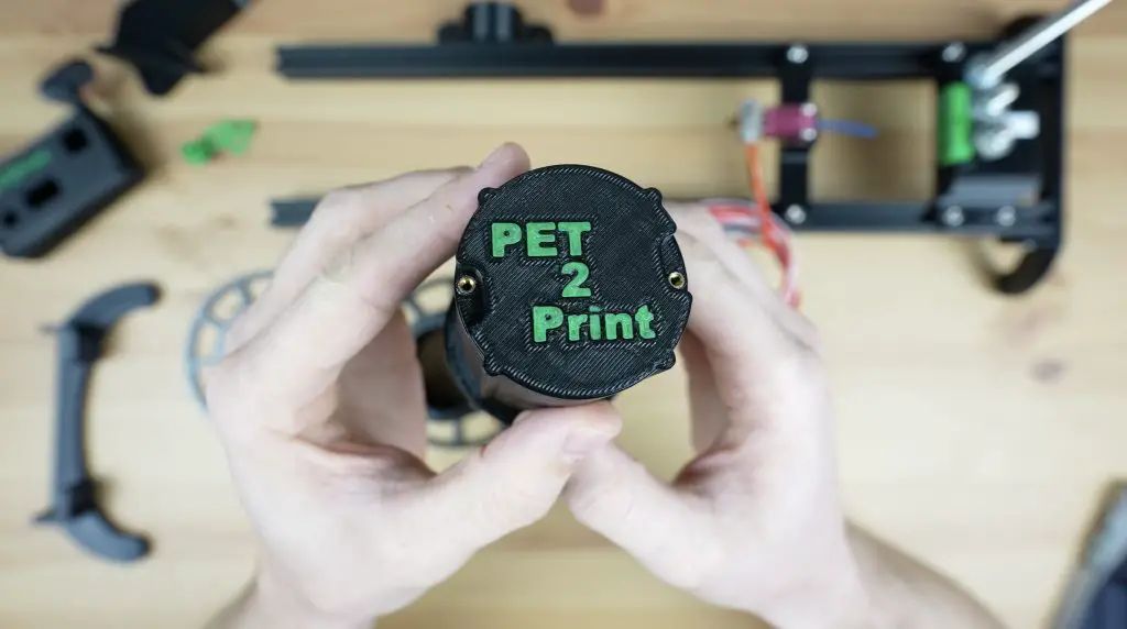
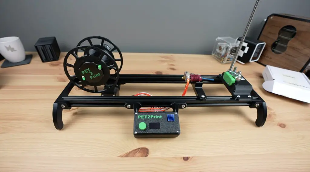
Designing The PET Bottle Recycler
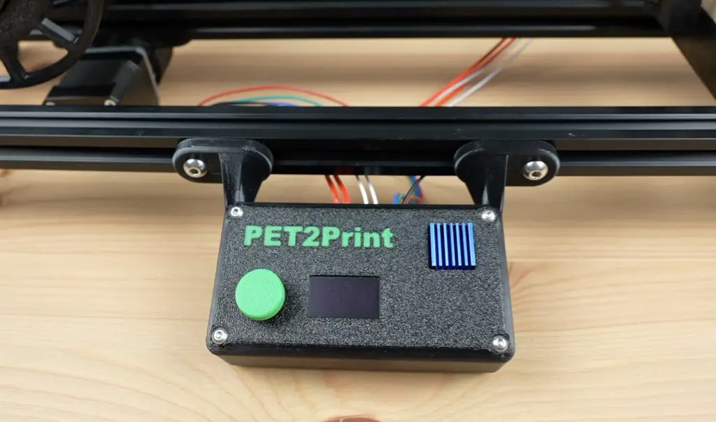
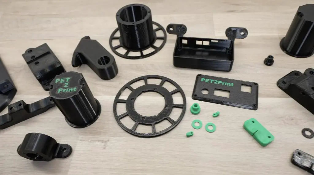
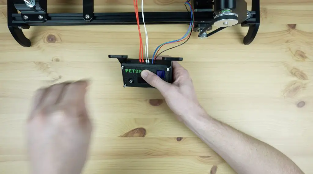
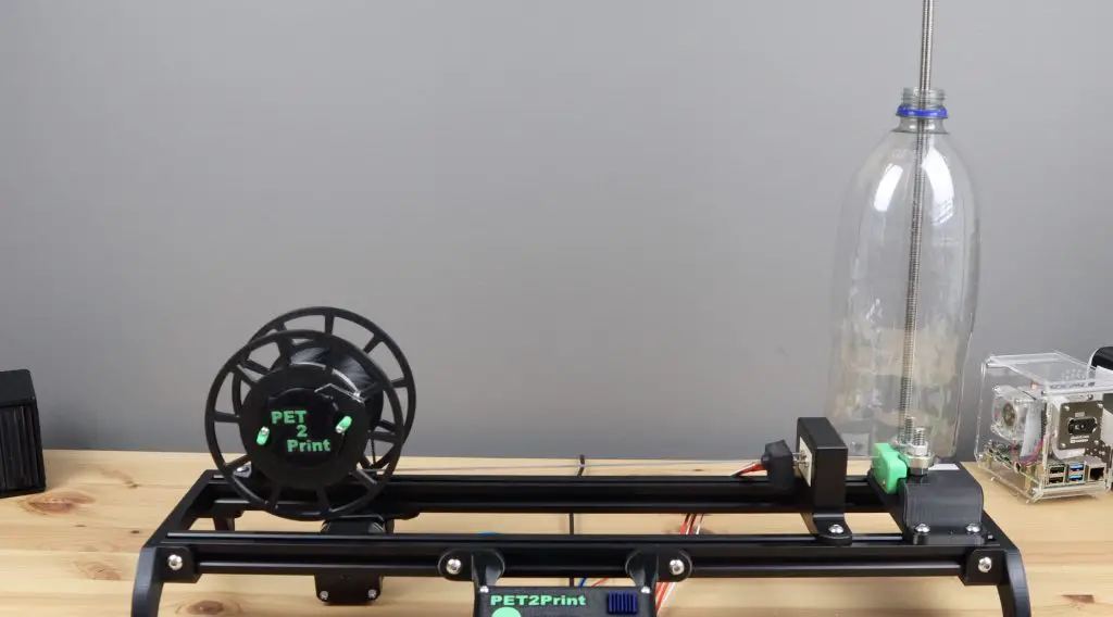
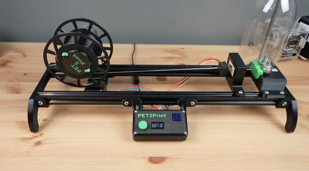
There are four main elements to the PET bottle recycler, which I’ve named PET2Print.
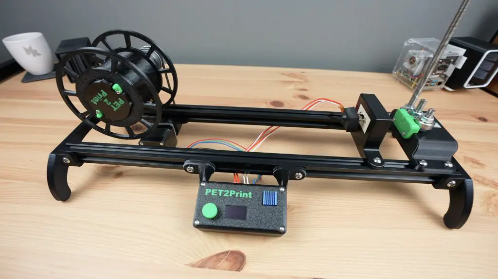
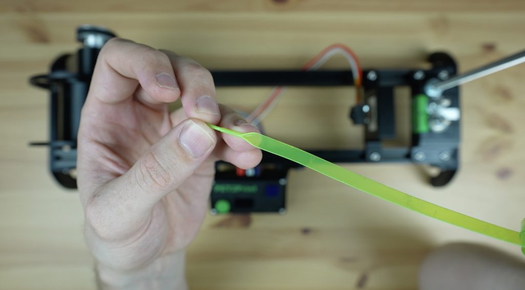
Starting from the bottle side, we’ve got a cutter that cuts the bottle into an even-width continuous strip.
Then we’ve got the hot-end which the strip is pulled through to partially melt and convert it into the size and shape for filament.
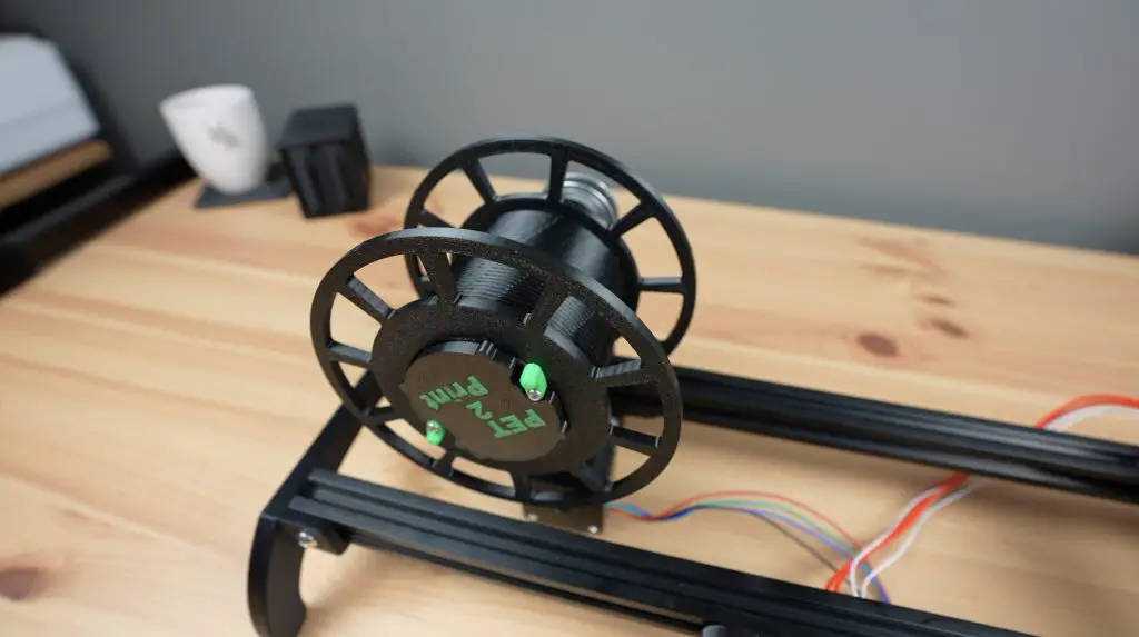
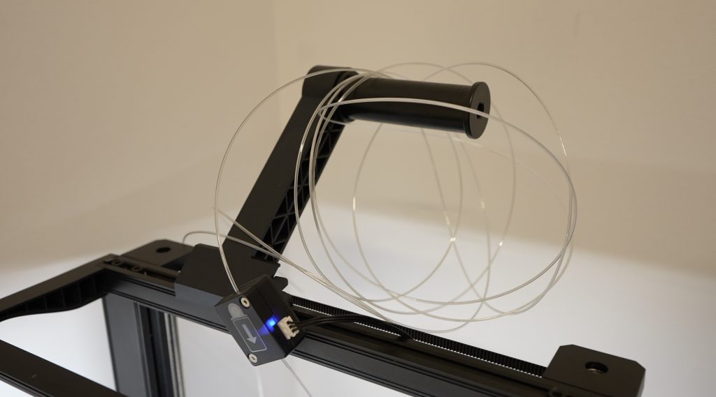
Then there is the reel which pulls the filament through the system and stores it for printing.
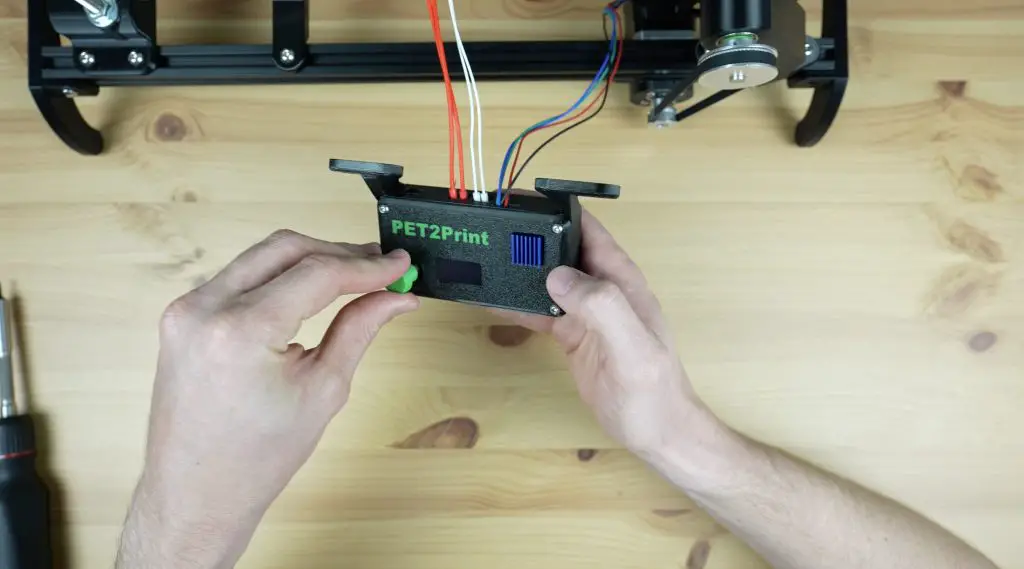
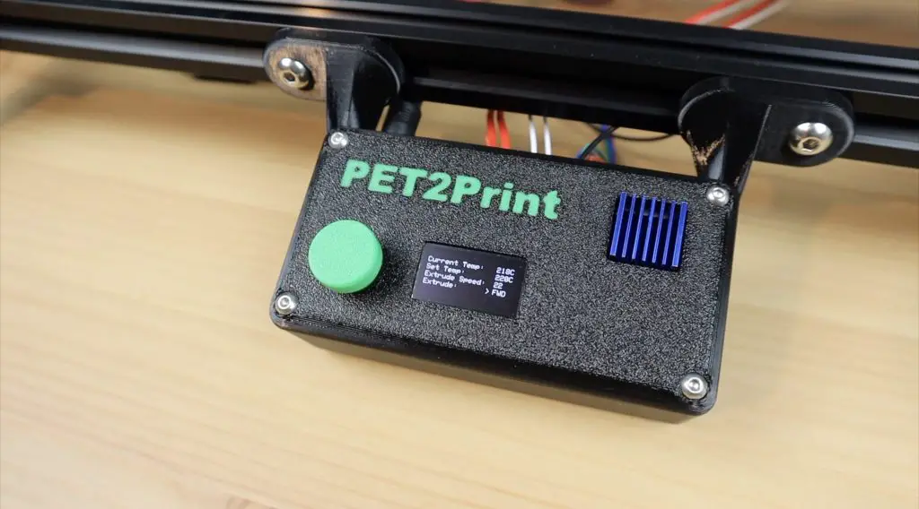
Lastly, we’ve got the controller on the front which controls the hot end temperature and the reeler motor.
The device doesn’t fully melt the PET strip, it just softens it enough to be folded over into a cylindrical shape that is the same 1.75mm diameter as common 3D printer filament.
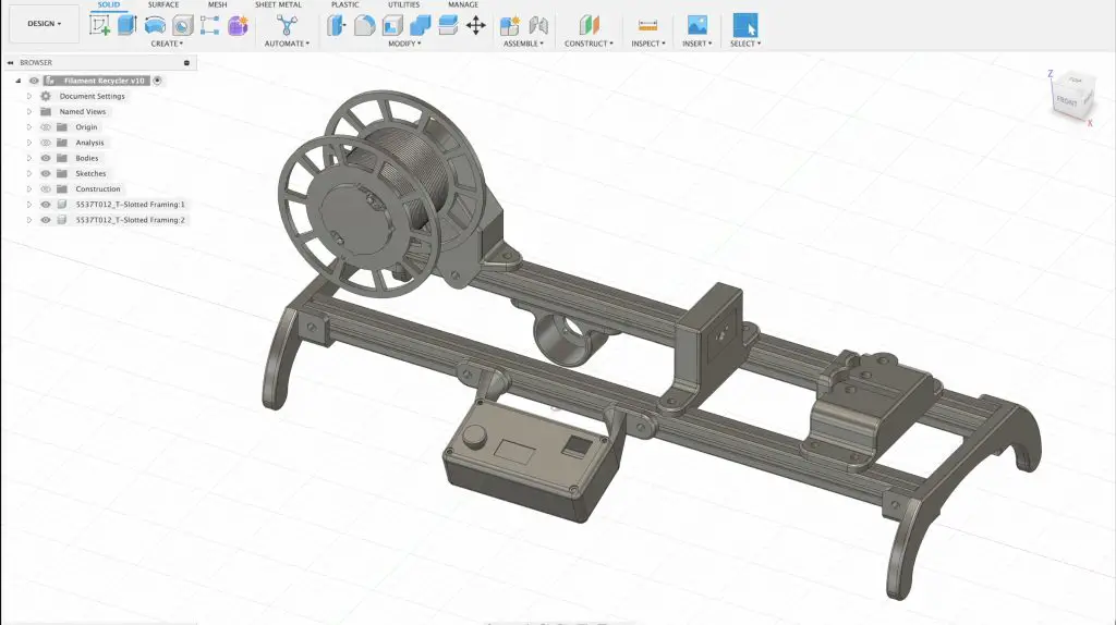
I started out by 3D modelling the design in Fusion360. I designed all of the 3D printable components and modelled some of the main bought-out elements to get the general shape and design right.
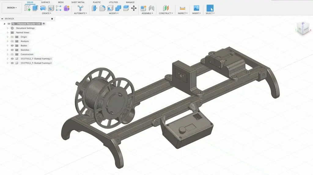
Then came a lot of 3D printing. I printed the parts out in PETG for added strength and I had to make adjustments and redesign some of the parts until I was happy with them.
Assembling The PET2Print
With all of the parts printed, we can start assembling the PET bottle recycler. We’ll again start on the bottle side with the cutter.
Assembling The Bottle Cutter
There are two main 3D printed parts for the bottle cutter, the base which holds the cutting mechanism and bottle support, and then the guide which just keeps the strip in the same orientation through the cutting bearings and when it feeds into the hot end.
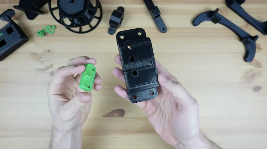
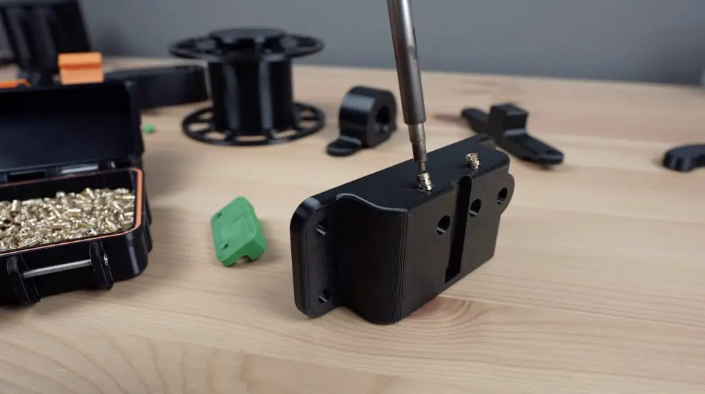
To join the two pieces, we need to add some M3 threaded brass inserts to the side of the base, which we’ll melt into place using a soldering iron.
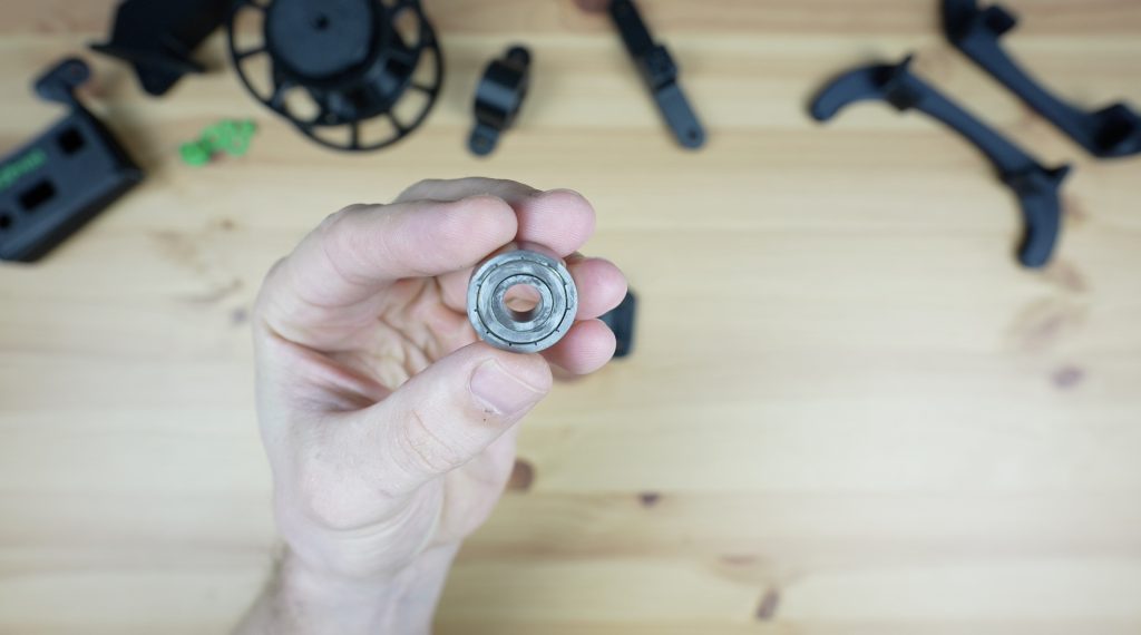
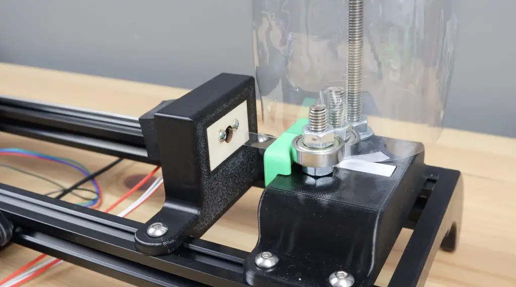
Before we screw the guide into place, we need to add the cutting mechanism. This uses two 608 ball bearings to cut the filament. These are really cheap and easy to get as they’re the same size bearings that are used for skateboard wheels and fidget spinners.
To turn them into a cutter, we need to sharpen one face of each bearing by grinding it flat. I did this on a bench grinder to make sure they’re kept square. You can also use a sanding disc or grinding disc on a grinder.
We then need to epoxy two M8 studs that are approximately 60mm long into the base to mount the bearings on. You can cut the M8 threaded rod using a cutting disc on a grinder, a Dremel or a hacksaw.
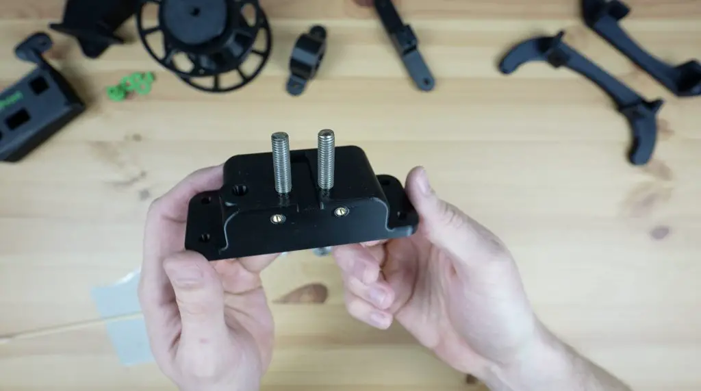
While we’ve got some epoxy mixed up, I’m also going to epoxy the 8mm shaft into the reel holder to use later.
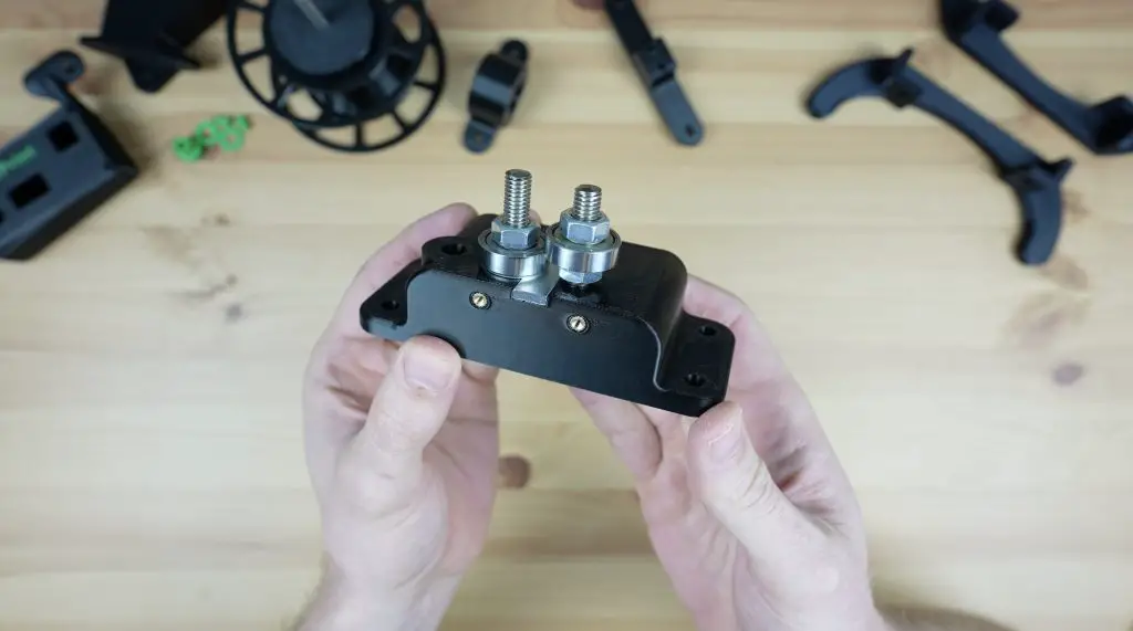
Once the epoxy has cured, we can mount the bearings onto the studs.
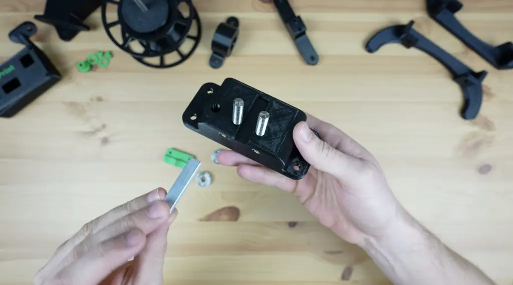
We also need to add a metal strip underneath the bearings, this stops the bottle from quickly wearing out the printed base. The strip will need to be trimmed from a piece of aluminium flat bar so that it fits into the cavity in the holder.
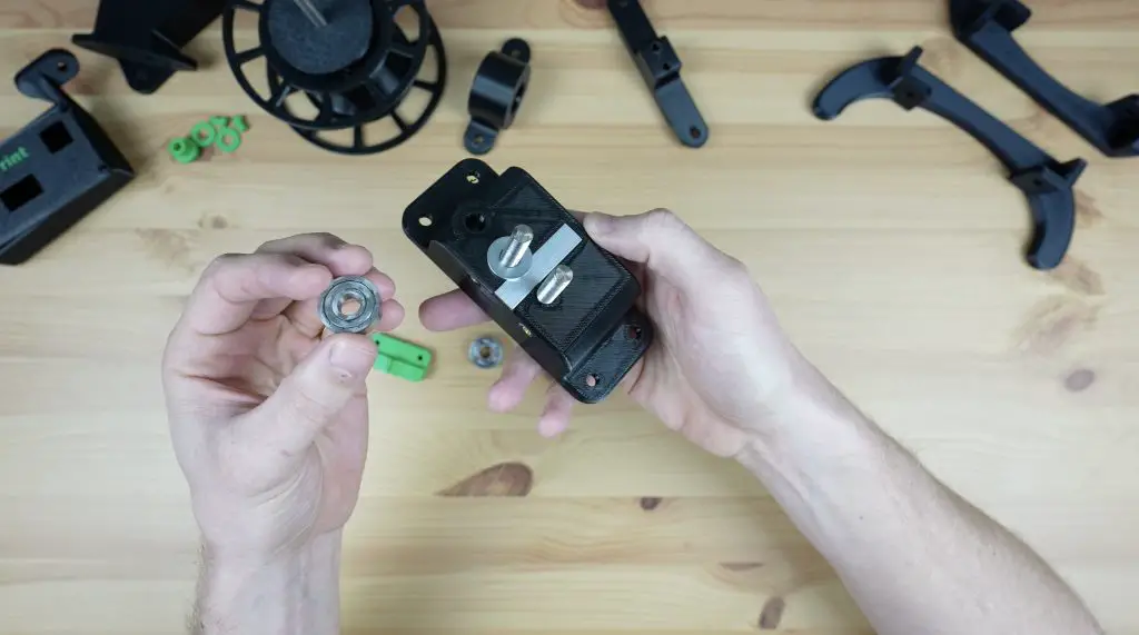
A small washer is used under the first bearing. The bearing then goes onto it with its flattened or ground face up, so that it doesn’t rub on the base. A nut holds it in place. We then add a nut to the second stud, then the bearing with the ground face down, just at the right height to contact the face of the first. A second nut holds the second bearing firm against the first bearing and the nut below it.
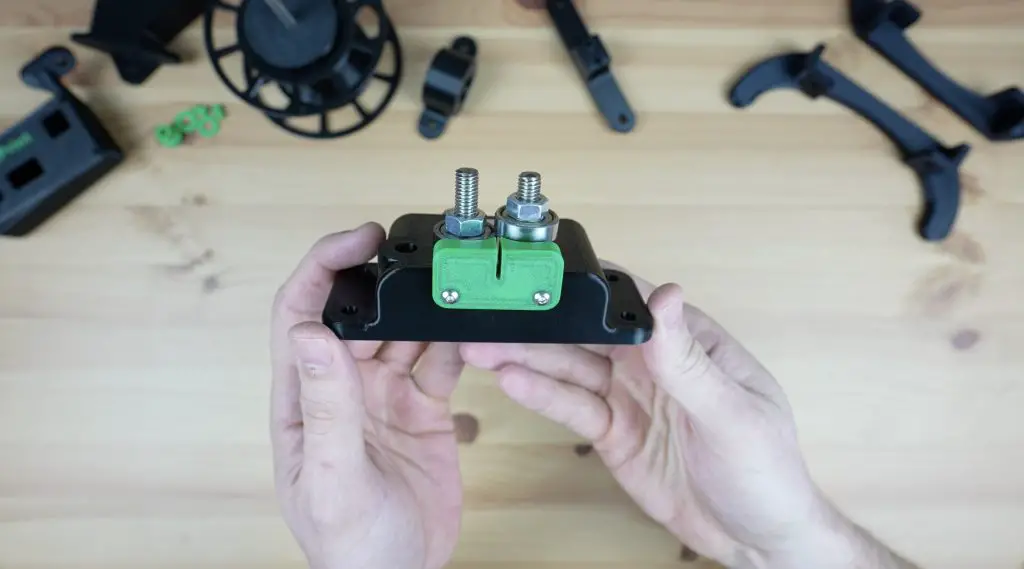
We can then screw the guide onto the front of the base with some M3 x 8mm button head screws.
To finish it off, let’s also add a M8 rod for the PET bottle stand. You can make this from the leftover length of M8 threaded rod, it needs to be long enough to hold the tallest bottle that you’ll use on the PET 2 Print (around 300-400mm). This will hold the bottle upright to feed the end into the cutter and it is held in place with a nut and washer on each side of the base.
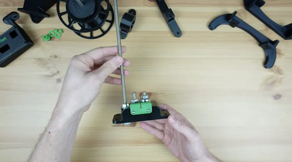
And that’s the cutter complete and ready to be mounted onto the stand.
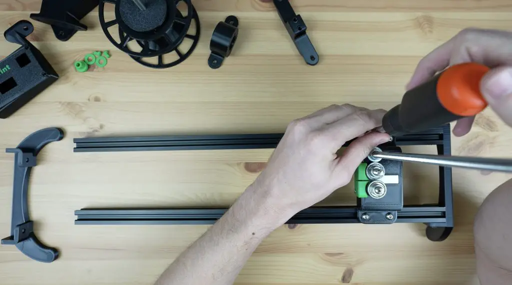
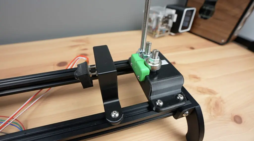
Assembling One Side Of The Stand
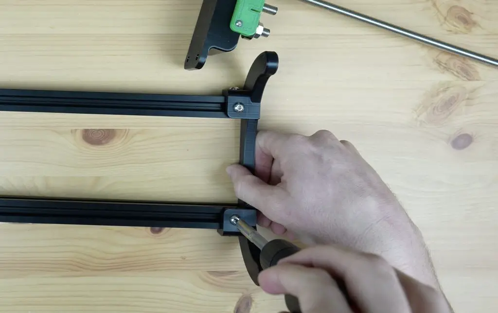
The stand consists of two 500mm lengths of 2020 aluminium v-slot extrusion and two sets of legs, one on each end. These are mounted with some M5 v-slot nuts and M5 x 10mm button head screws.
We can add one set of legs onto one end and then slide the cutter into position.
First Attempt At The Hot End
The hot end is a really simple part of the recycler, but it actually turned out to be one of the more tricky parts to get right. I’m going to skip through this initial design because there were a couple of things I didn’t think through when I designed it and it didn’t work.
Because the nozzle is going to be over 200 degrees celsius, we need a way to stop the heat from reaching the 3D-printed plastic holder. I thought I could use the heat break on the current hot end assembly, but I overlooked the fact that this meant that the strip wouldn’t fit into it. So I was back to the drawing board shortly after finishing it.
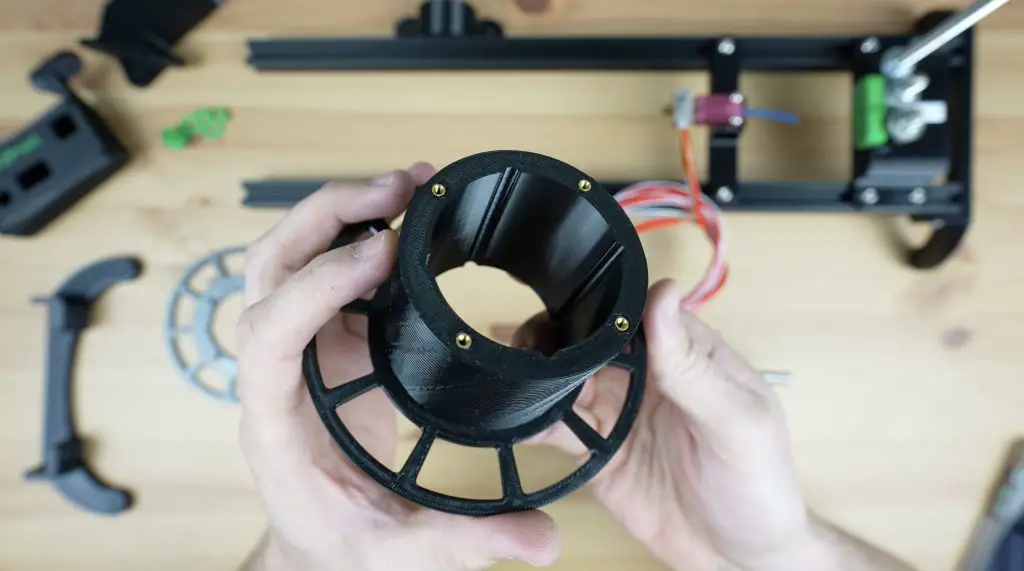
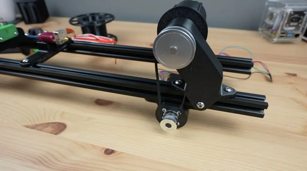
Assembling The Reeler
Next let’s move on to the most complicated part of the recycler, the reeler. This is the part that is driven by a stepper motor to pull the filament through the cutter and hot end.
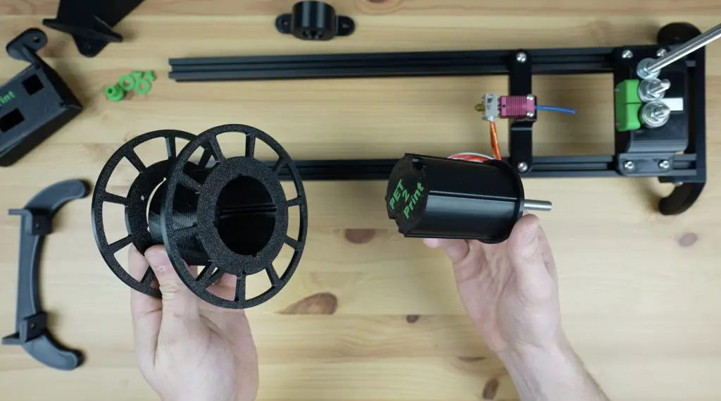
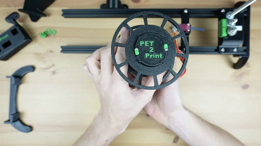
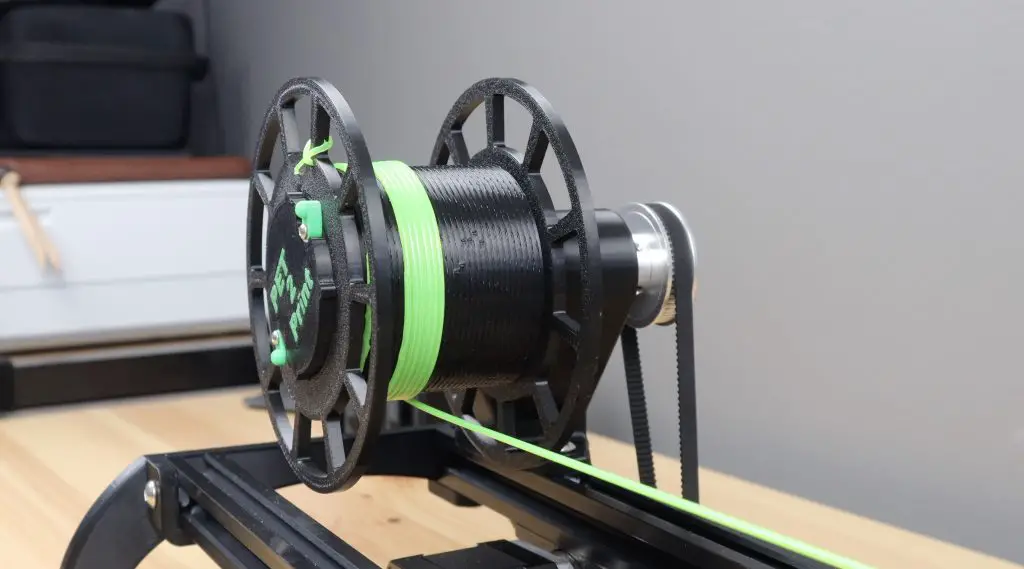
We’ll start by making up the reel.
The reel is something that I’ve changed quite a lot from the others I’ve seen online. On most other machines, the reel is fixed on both sides and you need to unwind the filament from the reel once it’s done. I wanted to avoid this, so I made the reel removable which makes it much easier to get the completed filament off of afterwards.
To finish the reel off, we need to melt some M2.5 threaded brass inserts into one half of the reel for the opposite end to screw onto. This is split to make it easier to 3D print without requiring supports.
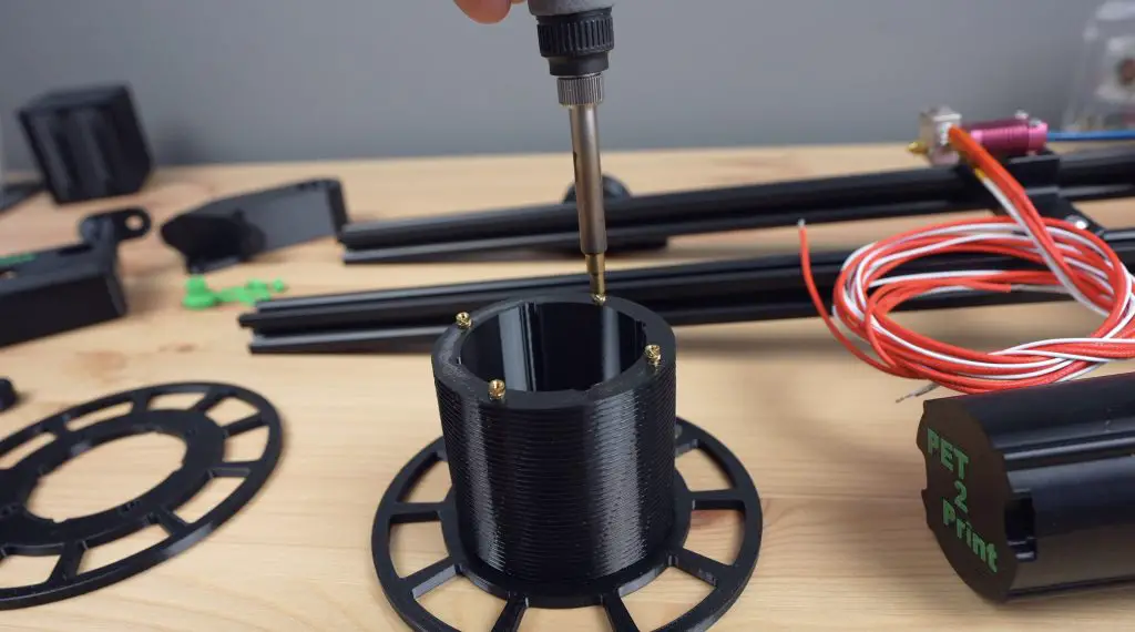
We also need to add some inserts to the other end of the reel holder for the small catches that hold the reel in place while it is running.
Then we can screw the reel parts together with some M2.5 x 6mm screws and the catches with some M2.5 x 12mm screws to finish them off.
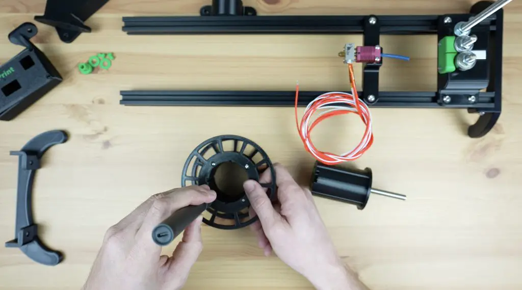
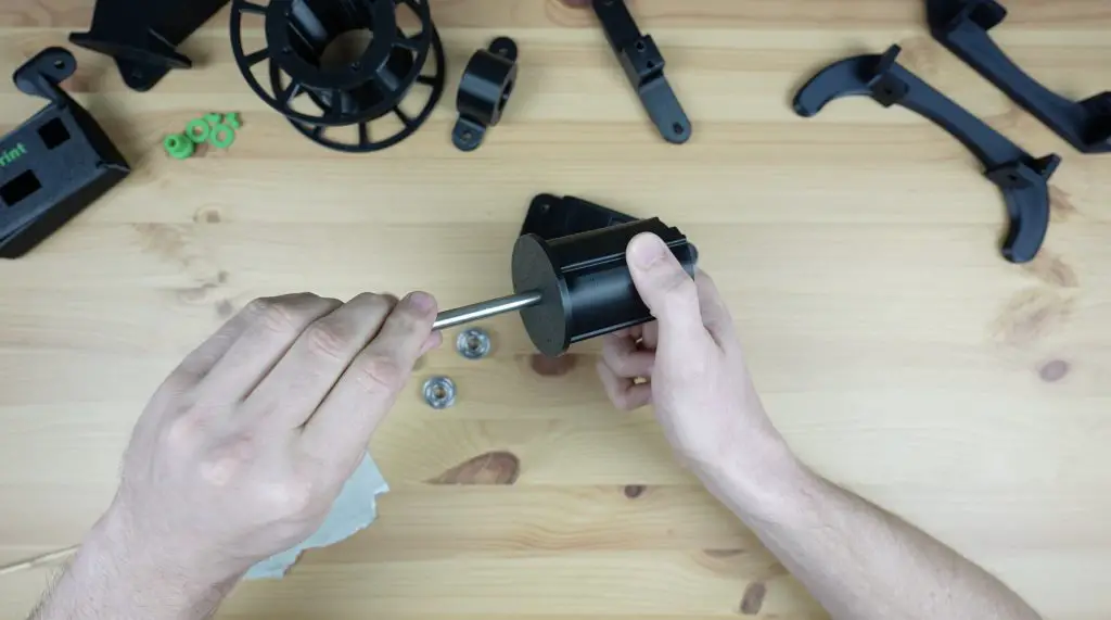
Next let’s press another two 608 size bearings into the reel stand, one on each side. We’ll use an 8mm shaft as a guide to keep them aligned while pressing them into place.
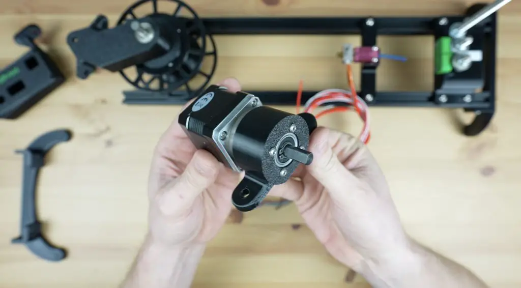
Next, let’s mount the motor onto its holder using four M3 x 8mm button head screws.
Then we can mount the base onto the top of the v-slot extrusion.
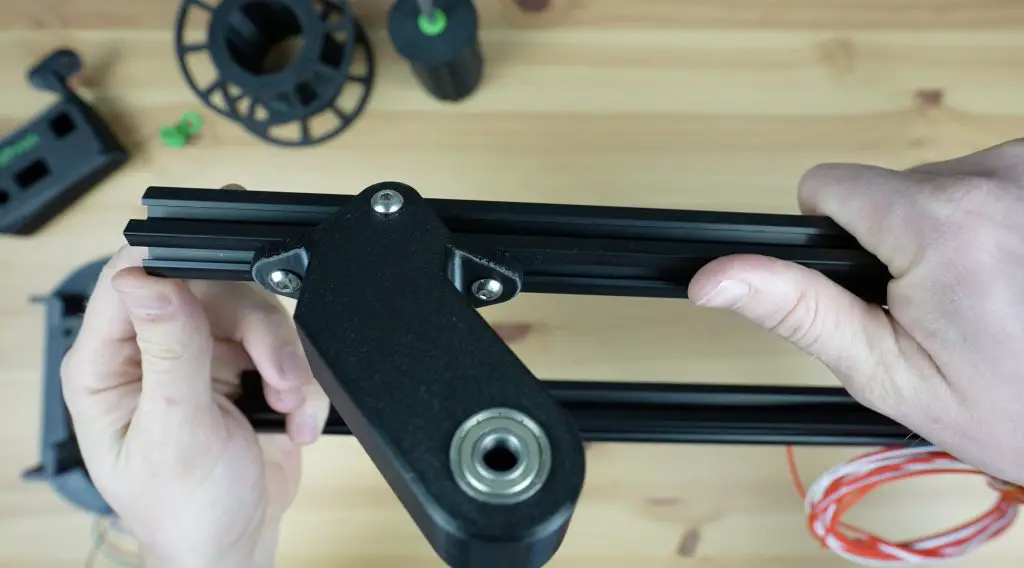
And the motor holder onto the underside.
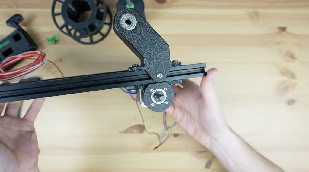
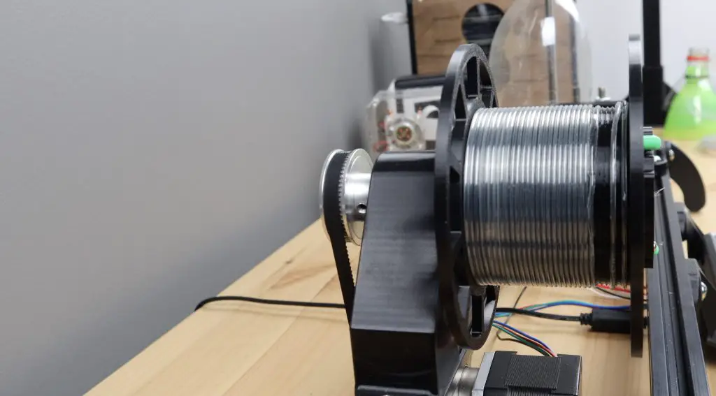
The reel is driven by the motor through a GT2 belt and pulley system on the back.
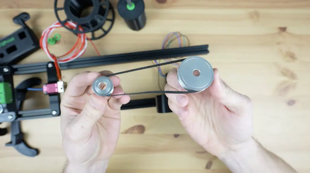
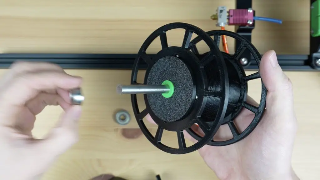
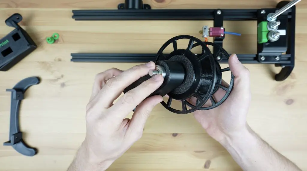
So we can push the reel’s shaft through its base with a spacer between it and the bearing, then another spacer on the opposite side. We then add the 60-tooth pulley to finish it off and the grub screw holds it in place. A 30-tooth pulley is pushed onto the motor shaft, with a belt connecting the two. Once complete, the shaft on the reeler can be trimmed to be flush with the face of the 60-tooth pulley.
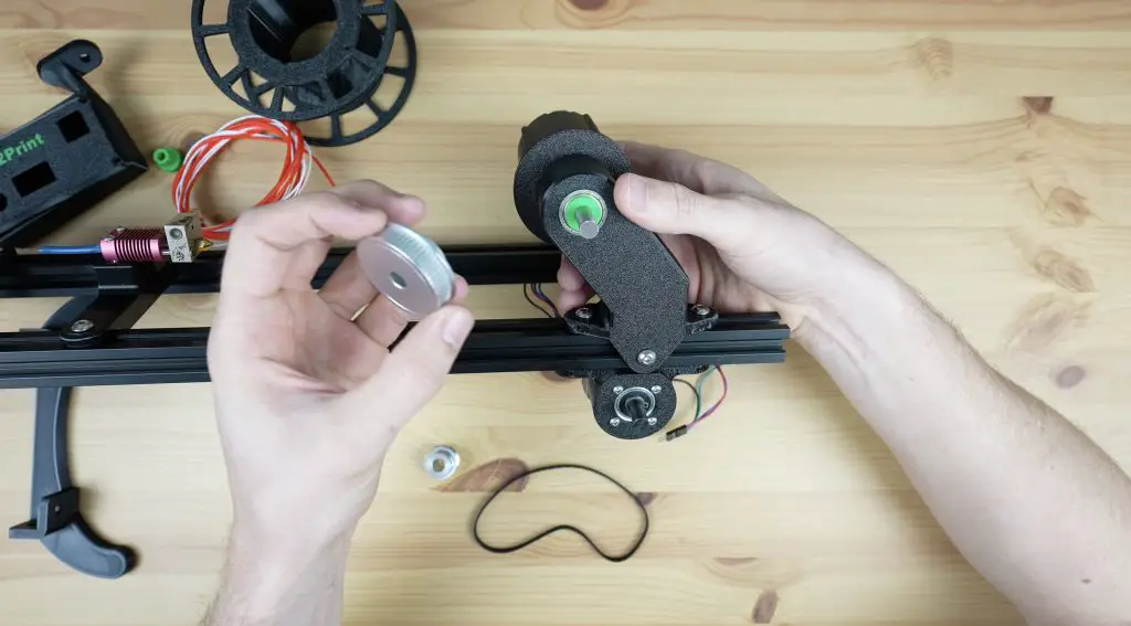
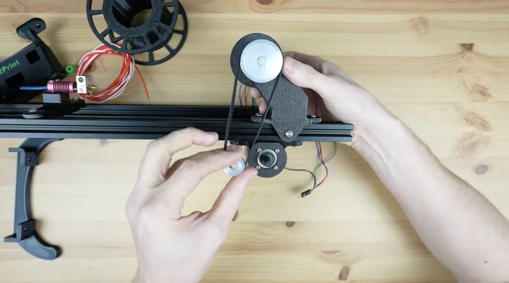
The belt is tensioned using the relative movement between the reel base and the motor holder, pulling them further apart puts more tension on the belt. This needs to be fairly well-tensioned but shouldn’t put enough stress on the components to bend or distort any of the 3D printed parts.
Assembling & Programming The Controller
Now that we’ve got the mechanical parts in place, we need to add the controller.
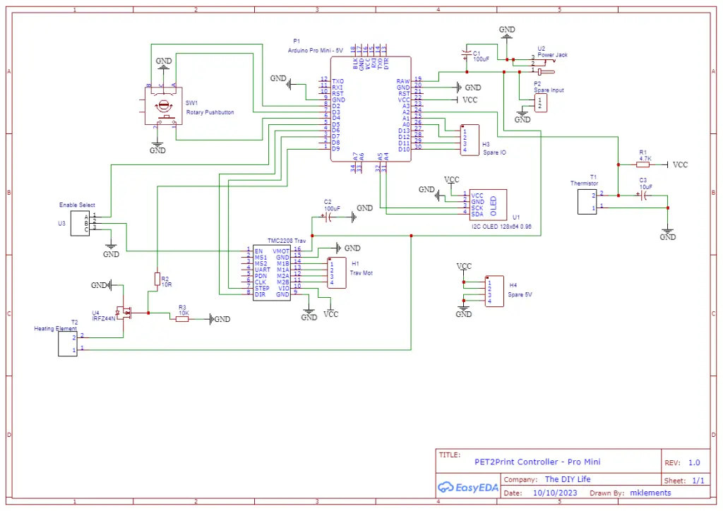
If you read my previous design and build of the controller, I ended that off by saying that I wanted to make it a bit more compact. It was designed as a shield for an Arduino UNO, but by using an Arduino Pro Mini, we can make it much smaller.
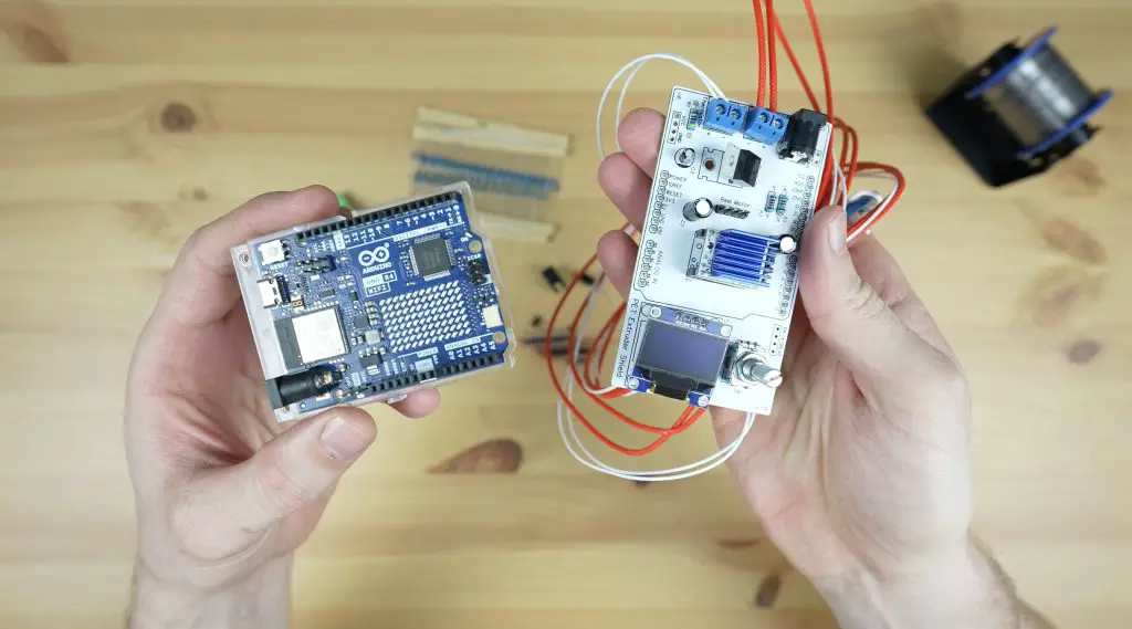
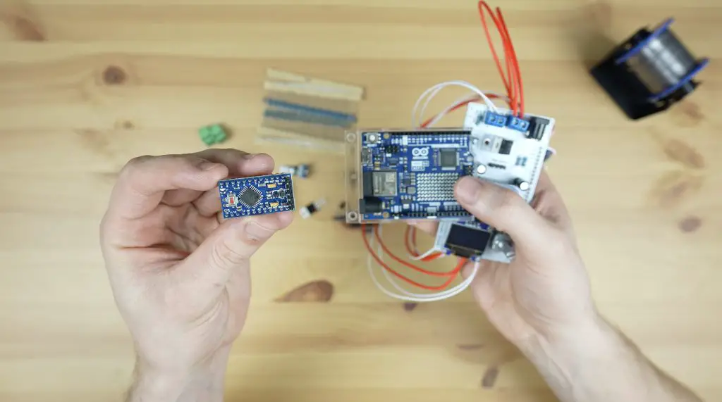
So I designed a new PCB that swapped the UNO out for a pro mini and brought the components a little closer together.
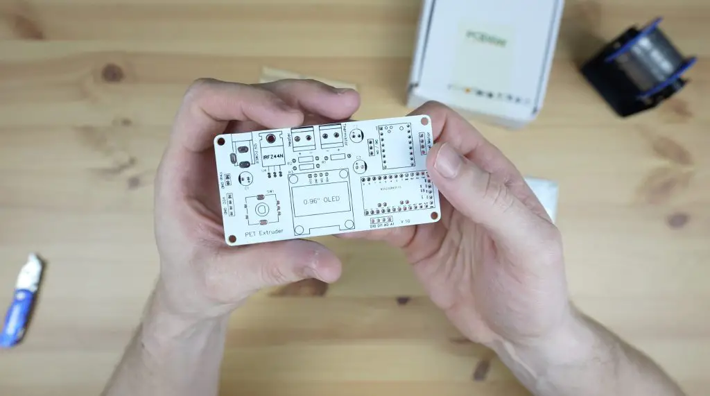
PCBWay then made them up for me in the same colour scheme as my previous shield.
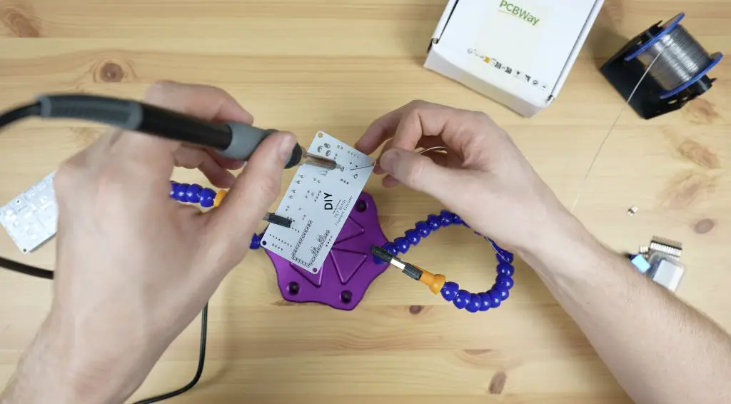
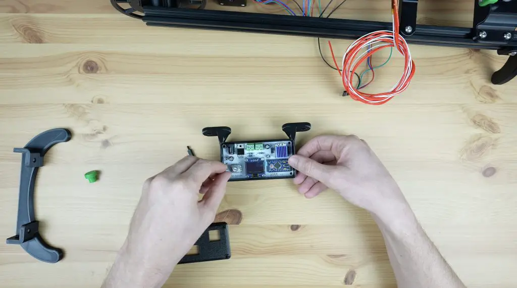
I soldered the components onto the PCB, starting with the smallest and working to the largest, with the Arduino going on last.
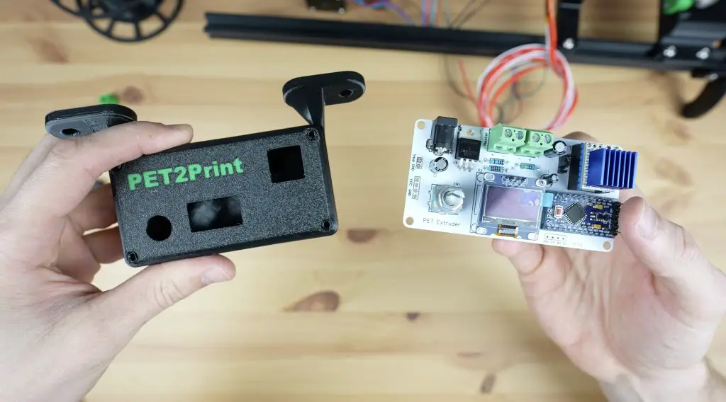
I also 3D printed a housing for the controller, but before we put it into the housing we need to program it and set up the stepper motor driver’s current limit.
Programming The Arduino
To upload the code to the Pro Mini, we’ll need to use a USB programmer. We just plug this into the Pro Mini and then into the computer to upload the code to it.
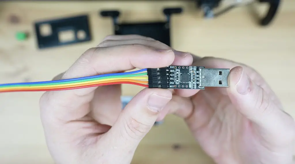
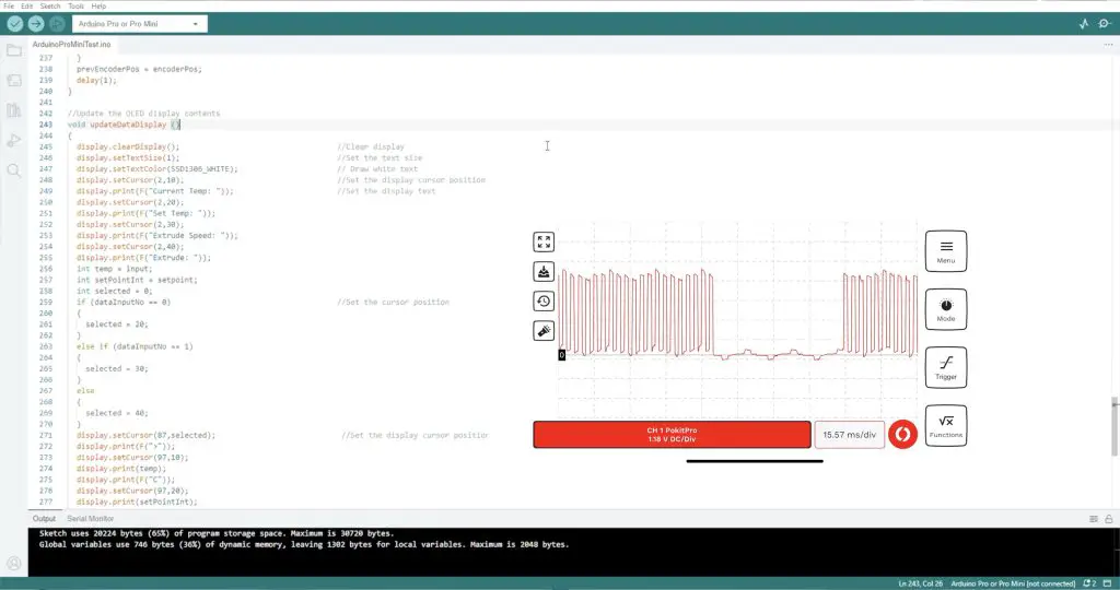
Make sure that you select the “Arduino Pro or Pro Mini” board type. Also check that you have the “Atmega328P (5V, 16MHz)” processor selected and that your programmer type is set to “USBasp”.
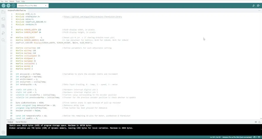
The sketch is available from my GitHub repository so that people can make changes and improvements to it.
Setting The Stepper Motor Driver Current Limit
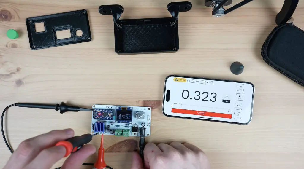
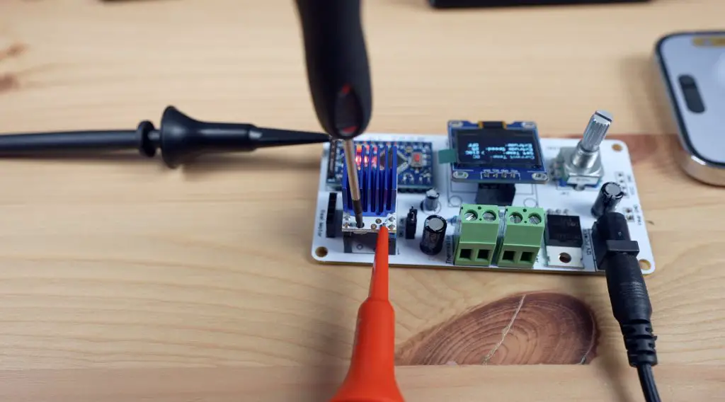
To set the current limit, we need to measure the driver’s reference voltage using a multimeter. I’m using my Pokit Pro multimeter with clamp leads.
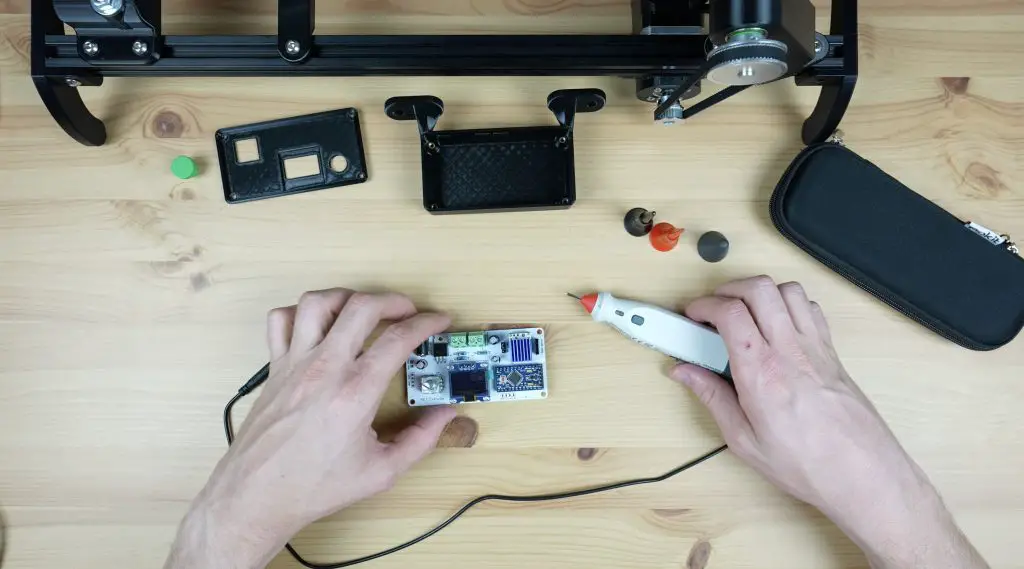
We then adjust the limit using a screwdriver to turn the onboard potentiometer to suit the rated current of the motor, which in my case is the same as the maximum current limit for the driver. So I’m aiming for a reference voltage of exactly 1V.
Display Update Issue
After setting the driver’s current limit and attempting to run the motor, I found another issue. When running the stepper motor, it sounded like it was intermittently skipping steps or stopping and this seemed to get worse if I sped the motor up.
I put the Pokit Pro’s oscilloscope onto the output and found that the Arduino stopped pulsing the stepper motor driver for brief periods of time, which was causing the driver to stop turning the motor.
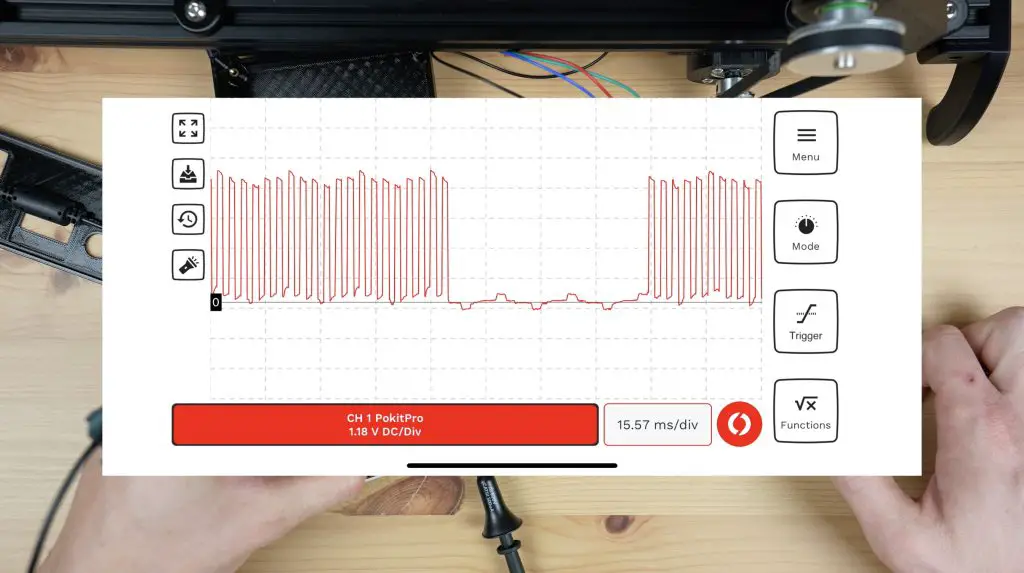
In working through the code, it seems like this happened each time the display was being updated. It looks like the Arduino takes longer to update the display than the period of time between pulses. So it just stops pulsing the driver while it finishes updating the display, which is obviously not going to work when we need a consistent pulling force. I tried making the display loop faster but didn’t have any luck with this. In the end, I had to modify the code so that it no longer updates the display when the motor is running.
This does limit the feedback on the display during operation, but won’t affect the overall design or functionality. I’ll have to investigate whether I can make the display or portions of the display update more quickly in the future.
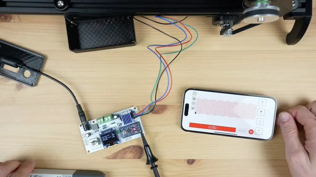
In any case, we now get smooth pulses from the Arduino and a consistent motor speed.
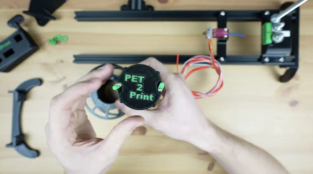
Mounting The Controller
To finish off the enclosure, we first need to add some M3 threaded brass inserts into the bottom to screw the PCB to.
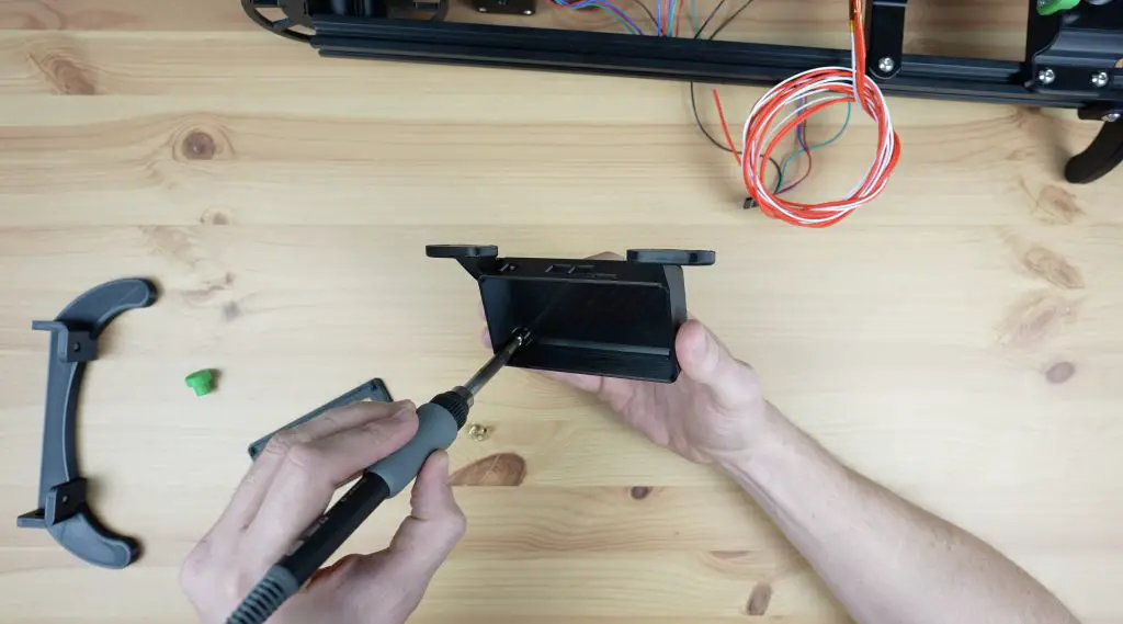
The PCB is then held in place with some M3 nylon standoffs which double up as a means to hold the top cover in place.
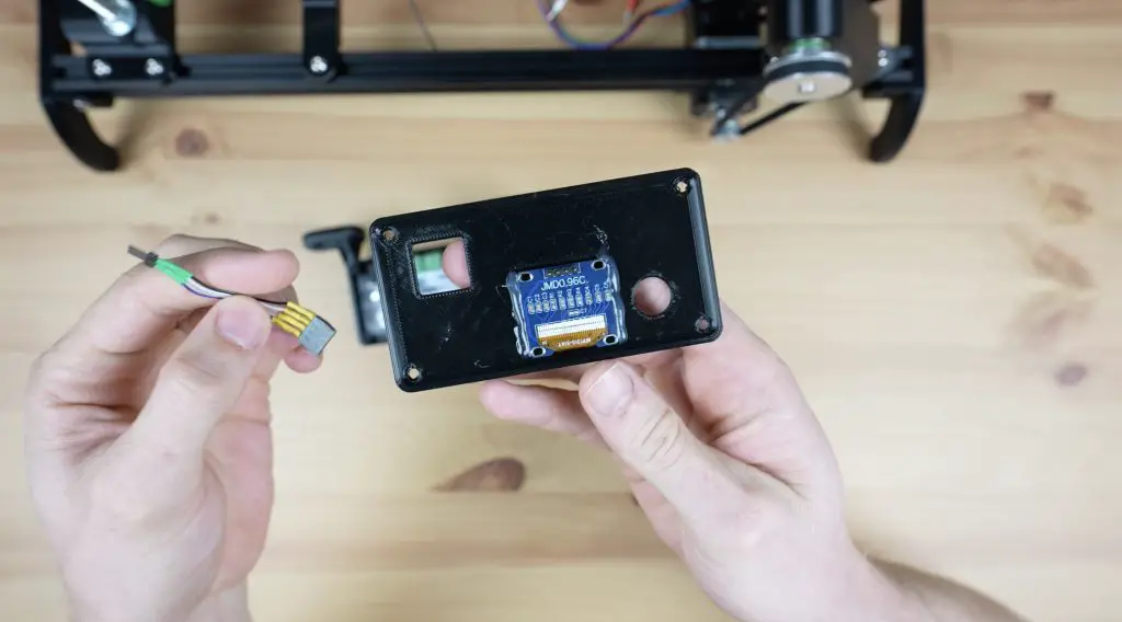
I’m glued the OLED display to the inside of the top cover with some hot glue and I’ll connect it to the PCB with a short ribbon cable.
We can then screw our element and thermistor into the terminals, plug in the stepper motor and then close it up with some M3 x 8mm button head screws.
A 3D-printed knob gets pushed onto the rotary push button and we can mount it onto the base.
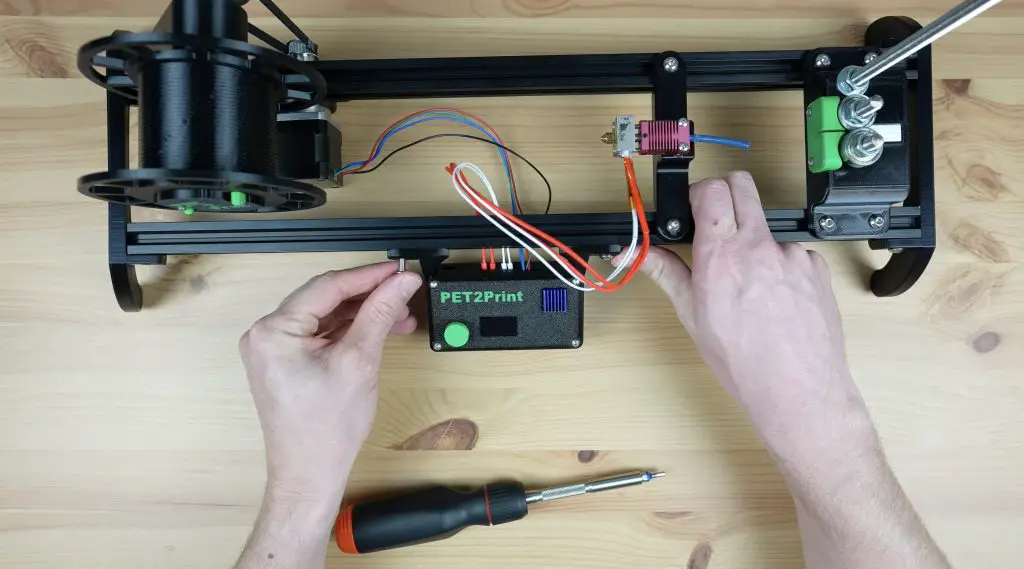
With all the components in place, we can install the second set of legs to close off the ends of the extrusions.
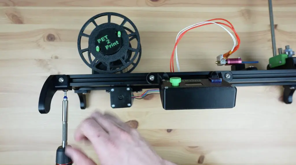
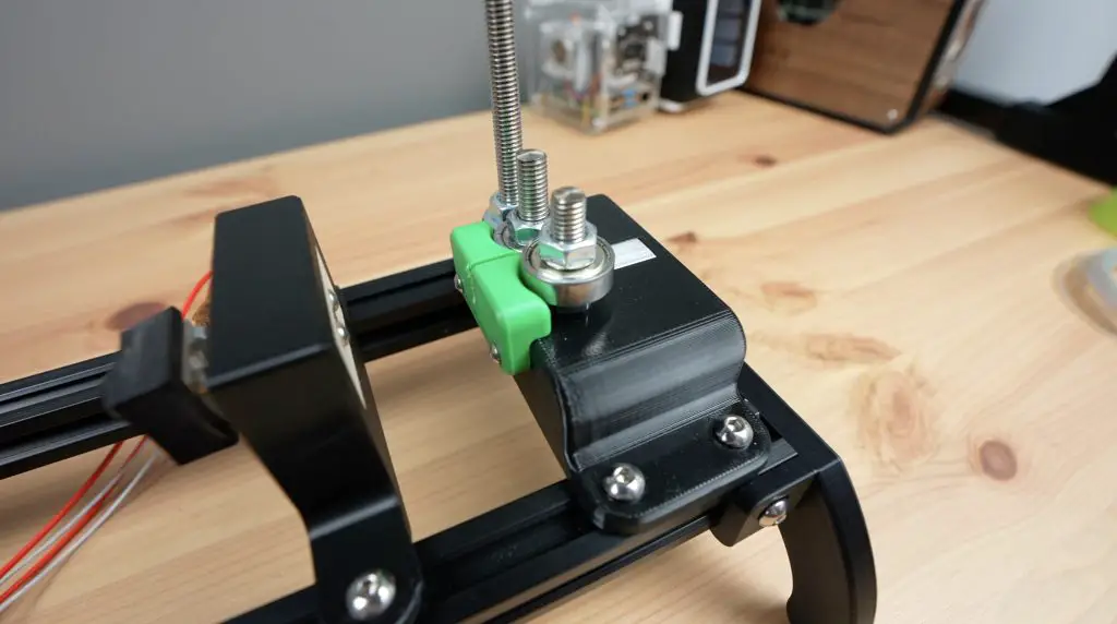
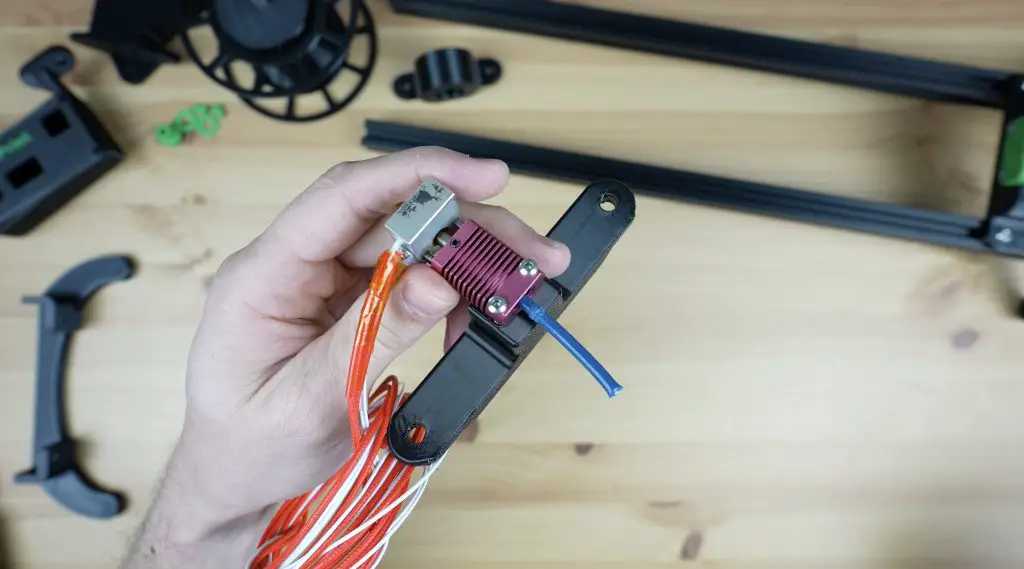
Second Attempt At The Hot End
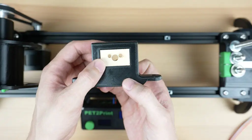
Now that we’ve got the other parts working, let’s go back to the hot end. As mentioned earlier, the device makes filament by softening the strip and rolling it over in the hot end to form a cylinder. This means that the strip needs to start being heated right from the time it enters the hot end or it’ll be very difficult to pull through. So, I redesigned the hot end holder so that the strip passes through the holder and directly into the heat block without any restrictions from the heat break.
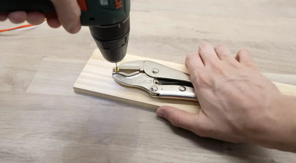
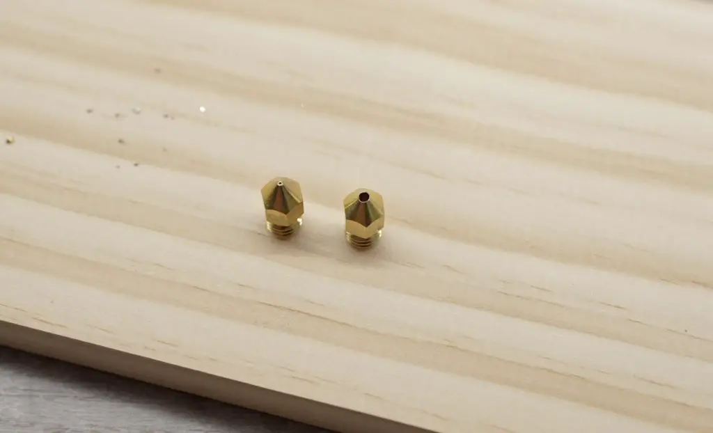
The nozzle is a standard 0.4mm nozzle, so we need to first drill that out to the filament diameter. We’re aiming for 1.75mm but the filament expands a little after it leaves the hot end, so we’ll drill it out using a 1/16″ drill bit, which is just under 1.6mm.
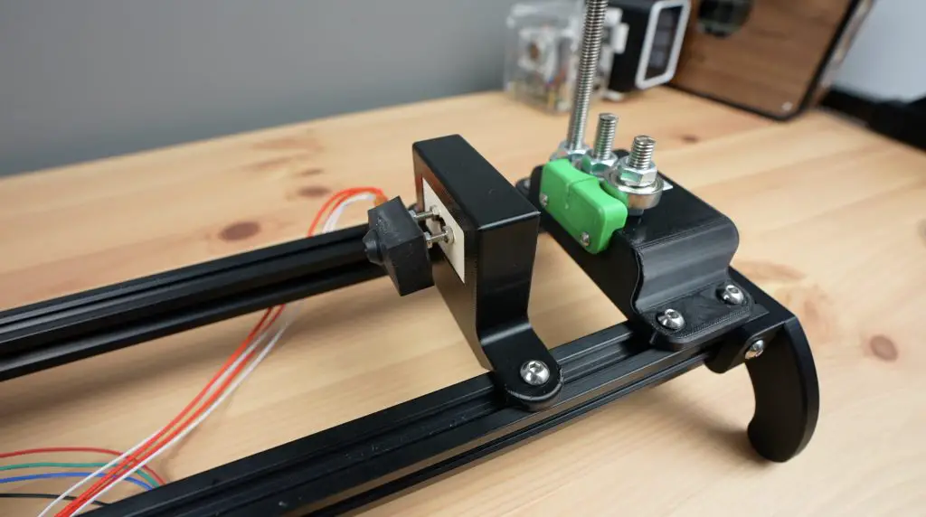
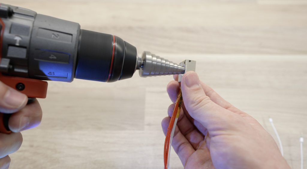
The back of the heat block has a small tapped hole for the heat break. We’re going to open this up with a tapered drill bit so that it is slightly larger than the strip width. The taper will then help to gently fold the edges over until we reach the nozzle diameter.
We can then mount the heat block onto the holder. I’ve used some M3 x 40mm button head screws through the heat block and then nuts to hold it onto the plywood plates on each side of the 3D-printed holder. The plywood plates act as the heat break in this design and stop the screws from melting the plastic holder.
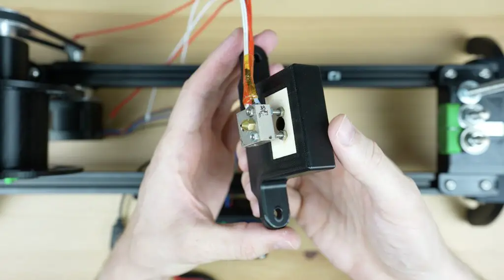
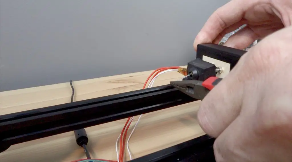
We can then re-attach the terminals and we’re ready to try it out.
Turning A PET Bottle Into Filament
To run the PET bottle recycler, we first select the target hot end temperature. I’ve found that 215°C to 220°C work well with my bottles. We can then select the motor speed, for which I use 22 to 25. These are just arbitrary units, they don’t relate to rpm or rotational speed. We can then turn the motor on or off, forward or in reverse, with the last menu item.
Now we just need a PET bottle to turn into filament. To prepare a bottle, we first need to wash it out and then remove the label and residue as well as any date markings. I found that acetone works well for this. If you don’t remove the label residue, it’ll clog up the hot end and/or cause your printed layers to delaminate.
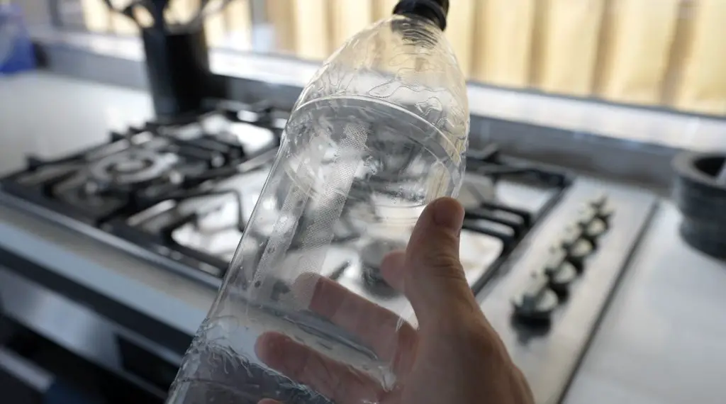
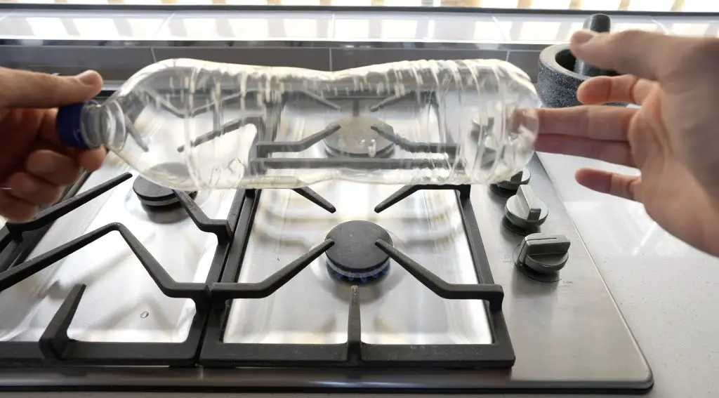
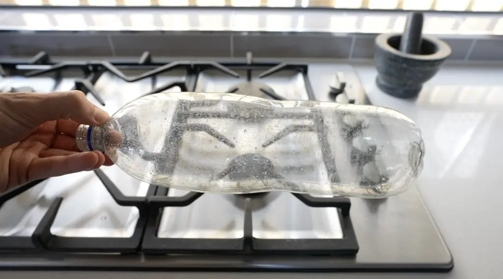
The bottle cutter works best with a smooth surface and most bottles are rippled in some way. You can smooth them out over some heat, like a stovetop, with a drop or two of water inside the bottle to pressurise it slightly. Be very careful when working with and opening the bottle as the hot air or steam can cause burns – it is best to use gloves.
We can then cut off the end of the bottle, cut a starter strip and feed it into the cutter.
We’ll need some needle nose pliers to pull the end of the strip through the hot end, which has now preheated to 220°C, and then onto the reel.
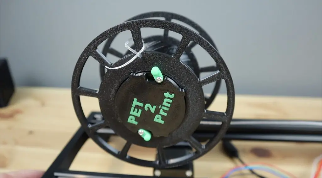
The reel has a small hole on one spoke which we can feed the end through to tie it off. You might need to keep a finger on the knot until there is tension on the filament to lock it into place.
Finally, we can turn on the reeler motor to continue pulling the filament through the hot end and onto the reel.
Now we just wait for it to turn the PET bottle into filament. You can also cut the bottle beforehand to reduce the load on the motor, you’ll then just feed the strip directly through to the hot end without the bearing cutter in place.
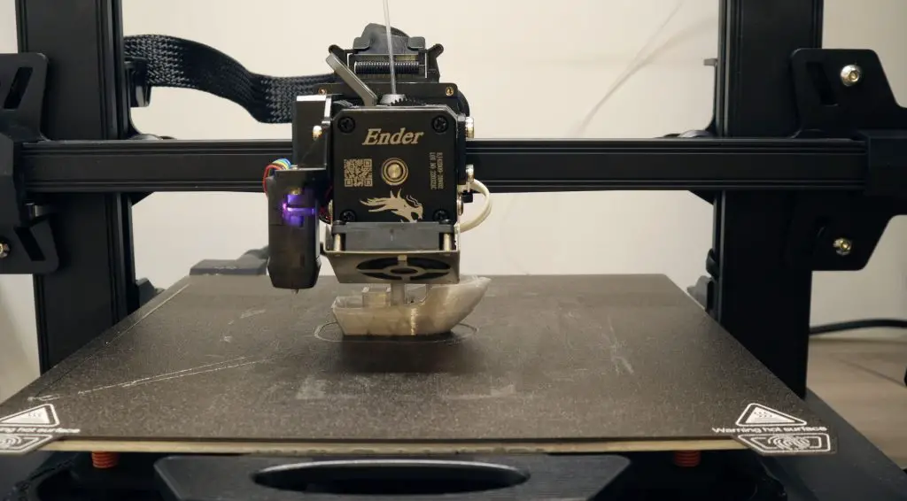
Test Prints With PET Bottle Filament
Once the bottle has been converted into filament, we can transfer it from the reel over to the 3D printer to try a print.
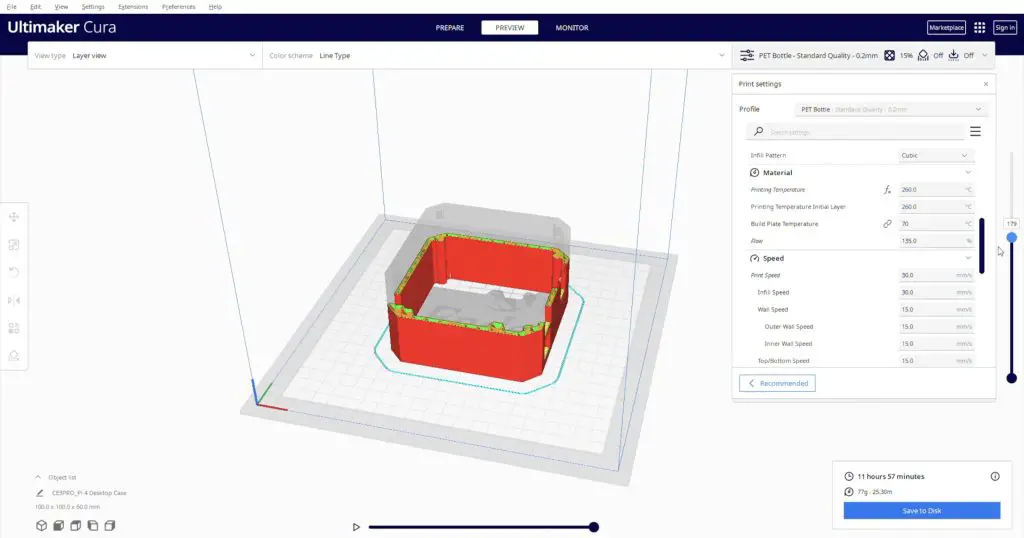
I started out by printing a benchy and calibration cube to see how they turn out. There is a bit of adjusting to do on the first few prints as the PET filament is not quite a solid 1.75mm section, it is hollow in the middle. I found that increasing the flow rate to about 135% gets good results. I printed with a bed temperature of 70°C and a hot end temperature of 260°C.
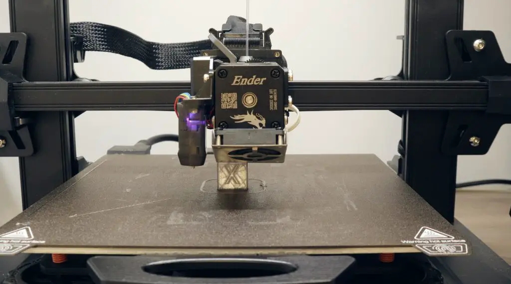
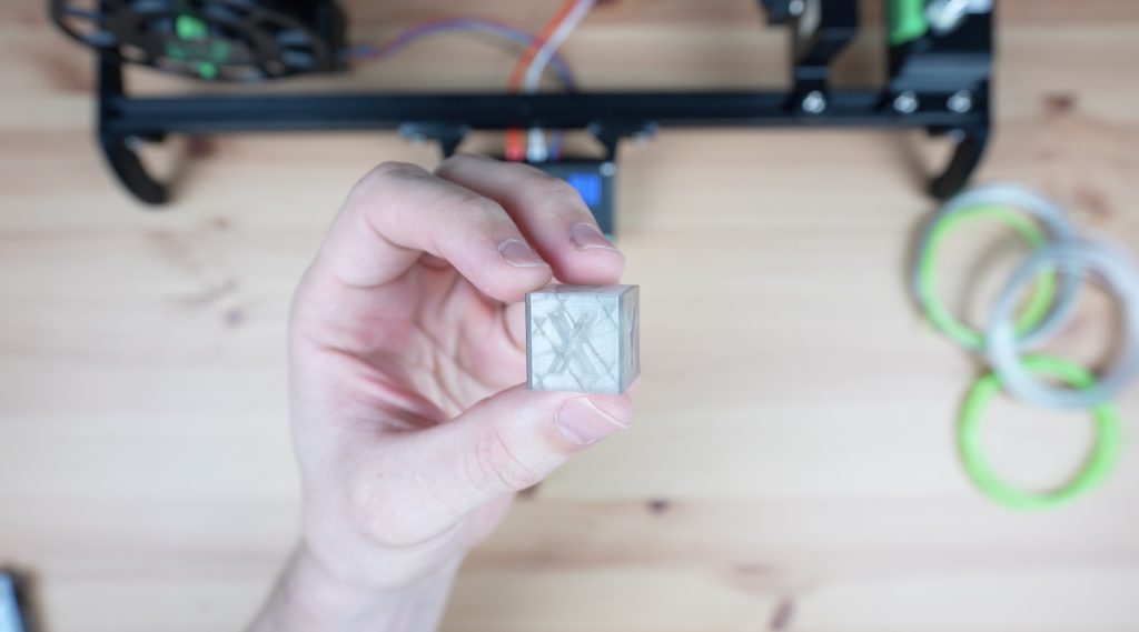
Once I had the settings right, I was actually pleasantly surprised by how well this filament prints. The calibration cube came out looking really good.
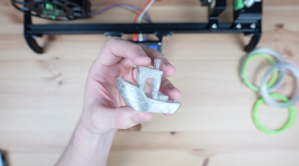
The benchy showed a few signs of stringing and a little under-extrusion in places but is also really good for homemade filament. It’s obviously not as consistent as factory-produced filament but it’s usable for home projects.
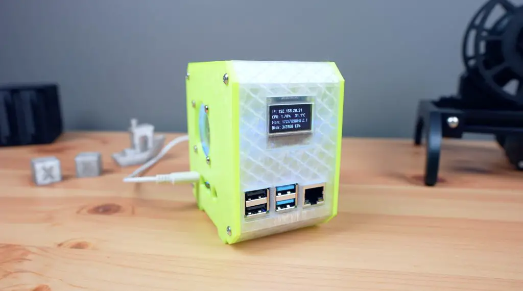
3D Printing A PET Case For My Raspberry Pi
Once I was getting consistent printing results, I converted a few more bottles so that I could print a case for my Raspberry Pi.
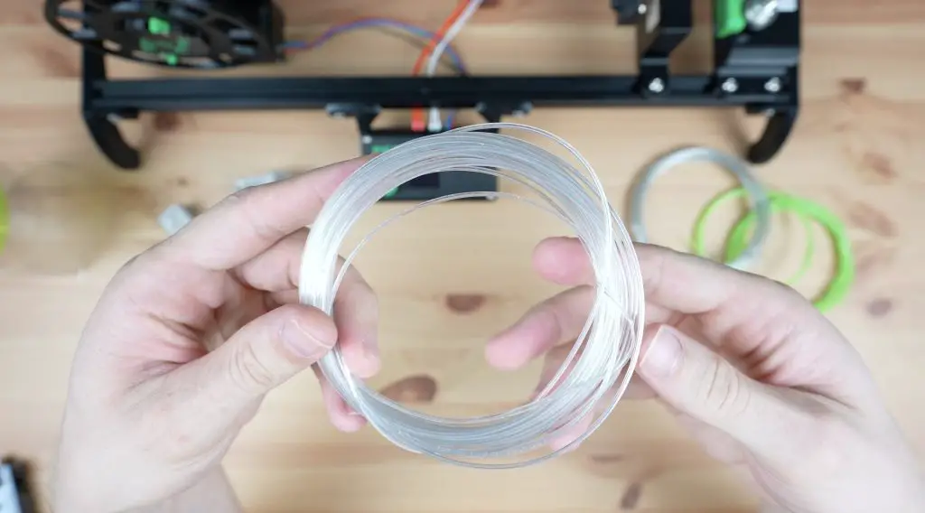
This highlights one of the drawbacks of this process. You get about 6-7m of filament from a 1-litre bottle, but with the hollow centre and having to increase the flow rate to compensate for this, it gets used up quite a lot faster than the standard solid 1.75mm filament. It’s also messy to store on the filament holder as it doesn’t like being coiled up.
To print my standard Pi case with no supports, I need 25m of PET filament and this is with a really low infill density and only 2 walls. So I need to swap a new roll of filament onto the printer 5 times for a relatively small print. This is manageable if your printer has a filament runout sensor but it’s still a bit of a nuisance.
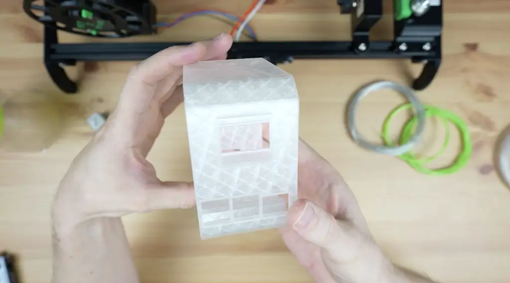
The case body also came out surprisingly well with just a little stringing and again some under-extruded areas. With the partially transparent walls and infill visible, it’s not obvious.
I even used the coloured Mountain Dew bottle for the printed side panels as well.
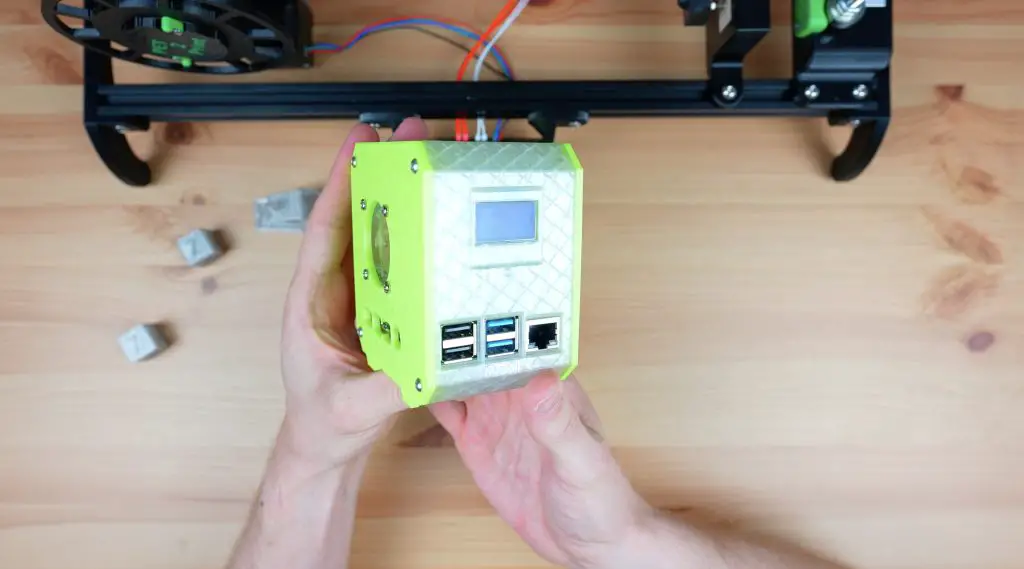
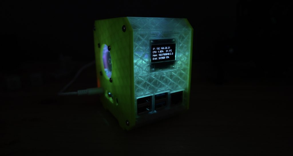
What do you think of the completed case? It’s really cool to think that this was once 5 Coke bottles and 2 Mountain Dew bottles. It also looks great in the dark as the RGB fan illuminates the body of the case.
Final Thoughts On The PET2Print
Overall I’m really happy with how my PET2Print recycler has come out. There are a couple of improvements I’d like to make to it, like getting the displayed temperature to be able to be updated while the motor is running, and perhaps designing a spool mount for precut bottle strips instead of the bottle cutter. It would also be helpful to be able to splice two lengths of PET filament together to avoid having to change the filament during a print but to date, it doesn’t look like anyone has found a reliable process for this.
Let me know what other suggestions you have to improve upon it in the comments section below. As mentioned earlier, I’ve put the code up on GitHub if you’d like to have a go at improving it – I’m sure there is a lot of room for improvement.
good afternoon. why did they give a link to the ssd1306 screen module in the list of components, although its pin arrangement does not match the scheme. in the diagram, your contacts go in this order (vcc-gnd-scl-sda) and on the module, the contacts go in this order (gnd-vcc-scl-sda). The ssd1315 module fits your scheme.
Can you tell me where the duration of the STEP parameter is in your program? Or does it depend on the current temperature?
Hi, I am curious as to how much this cost you to make?
A great feature would be to have a way to pause the process and joint the end of one bottle to the start of the next bottle so that you can have more that the limited lengths of filament.
Can make a kit and tell me how to buy it like everything included please
Obrigado por compartilhar seu conhecimento, ensinar é uma arte!
This is super cool! I love that you took the initiative to create your own PET bottle recycler when you couldn’t find one that fit the bill. The list of parts is like a treasure map for DIYers. I’m curious, how did you figure out which parts worked best together? And what was the most challenging part of the build? I once tried a DIY project and ended up with more screws on the floor than in the thing I was building! 😜
This is super cool! I love that you took the initiative to create your own PET bottle recycler when you couldn’t find one that fit the bill. I’m curious, how did you come up with the specific design? And what was the most challenging part of the build? I once tried a DIY project that seemed simple but ended up being a real headache. Can’t wait to hear more about your journey!
So I’ve been trying to follow your instructions and schematics but the circuit board is not working. I’m new to building electronics so I’m not sure where to start. When i plug it into my computer with the programmer it seems work just fine; the light lights up, the screen displays, and I can play with the options. But when i plug in the 12v power supply the light comes on for a split second then it goes dead, after the first time plugging it in the light never come on again unless I use the programmer. When I measure the voltage across the raw and gnd on the Arduino it shows as 12v which i feel is wrong. Any ideas on what I’ve done wrong?
Yes so do i
I think it should be with regulator to 5 v for elod and arduino
If u find a way let me know.
Thanks
Hi
I made this your project. But sadly its not working or even light up oled.
If i could have you email i will send my work and trubleshout it for me.
I used 12 v power and my pro mini is gone and i made it another one with 5v which still lcd is not coming up.
Many thanks
make sure your using the same oled he used, i got some different ones that were a little bigger and found that the vcc and gnd were backwards from the ones he suggested, when i swapped those connections around it displayed but it was garbled and static so i bought the ones he linked and the worked just fine
so I’ve tried putting a voltage regulator in before getting to the Arduino and that stopped it from frying, but best display i can get is static. I’m beginning to think that he used a 3.3v Arduino since that’s what it says on the pcb gerber files, gonna try that next
It’s possible that some of the generic Pro Mini’s don’t have a decent regulator on them and that they’re getting fried. Adding a regulator before the Arduino would correct this. I’m using a 5V Pro Mini, not 3.3V. The parts list and schematic is correct, the gerber files just have the wrong silkscreen text.