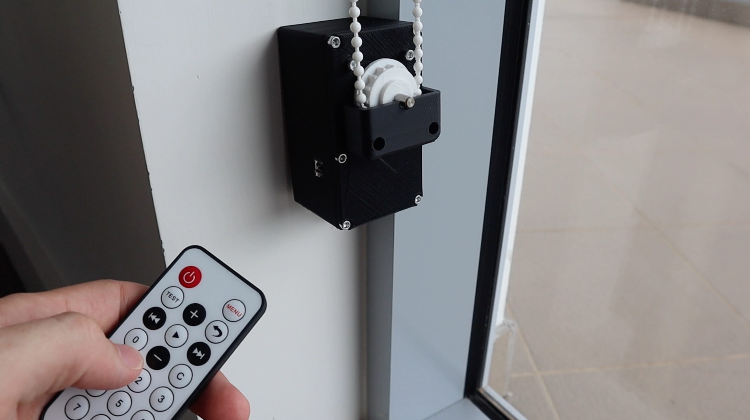
In this project, I’m going to be showing you how to make your own Arduino based Automatic Blind Opener which is operated using a remote control or through a smart home device, such as an Amazon Echo. This allows you to also set timers and build the opening and closing of your blinds into your routines. It not only makes your life easier, but can also improve your home’s security by automatically opening and closing the blinds at certain times in the day to create the impression that someone is at home when you’re away.
The design uses an Arduino pro micro and a A4988 driver to drive a stepper motor which turns a plastic gear which can be fitted onto most plastic ball chains, making it suitable for vertical and horizontal blinds. An infrared sensor is used to receive signals from a remote control or from an Alexa controlled infrared transmitter to partially or fully open and close the blinds.
Have a look at my video of the assembly with clips of the automatic blind opener in use or read on for the step by step instructions which include the 3D print files for download as well as the Arduino code.
What You Need To Build Your Automatic Blind Opener
- Arduino Pro Micro – Buy Here
- Nema 17 Stepper Motor – Buy Here
- A4988 Motor Driver – Buy Here
- Infrared Receiver – Buy Here
- 10K Resistor – Buy Here
- 100uF Capacitor – Buy Here
- Infrared Remote (With Sensor) – Buy Here
- Machine Screws – Buy Here
- Ribbon Wire – Buy Here
- Header Strips – Buy Here
You’ll also need to 3D print some components. If you don’t have a 3D printer, I recommend that you have a look at buying one, they have become relatively inexpensive and are a powerful tool for your work space. There are also a number of online 3D printing services which will print and deliver the components to your door in a few days.
How To Make Your Automatic Blind Opener
Print & Assemble The Housing
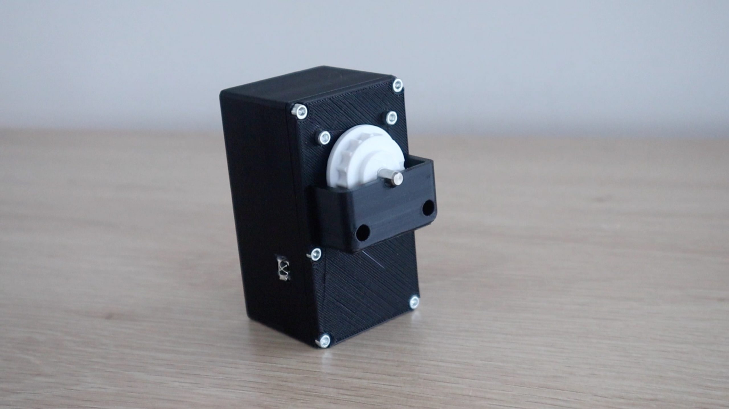
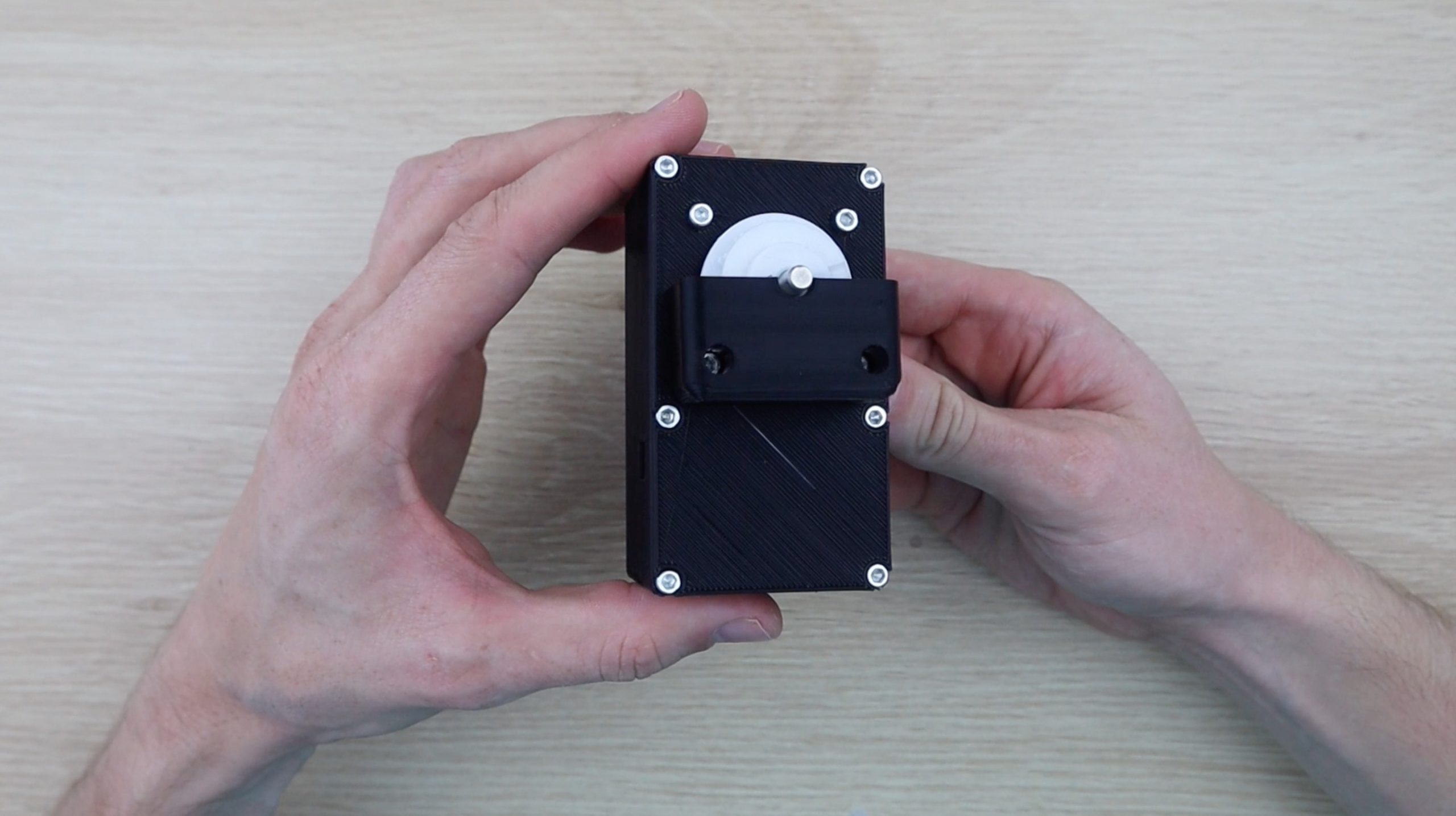
I designed the housing to be as compact as possible so that you don’t have a bulky box underneath each blind. These can be neatly tucked into a corner along the window frames and can be printed in a filament colour to match your walls or frames.
Download 3D Print Files – Blind Opener Print Files
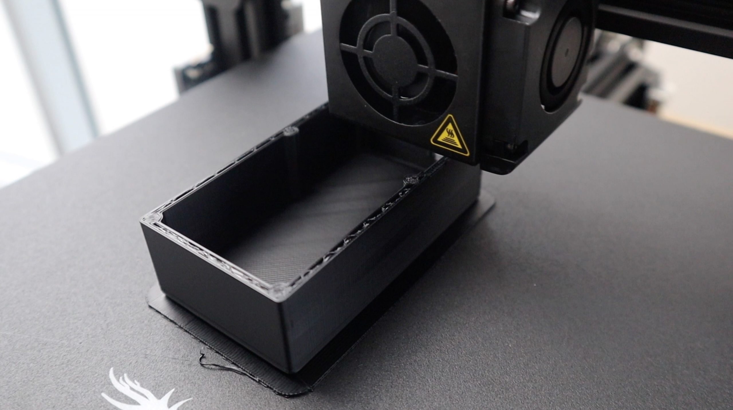
I printed the components in PLA using a 15% infill. I printed the housing in black and the gear in white, just so that there was some contrast between components for the project. It would be best to match the filament colour to your walls or frames.
The housing walls are quite thick so that you can easily drill holes through the back or sides to mount it to a wall or frame. The best would be to edit the model file and add your holes before 3D printing, depending on how you’re going to be mounting it. You can screw the back part of the housing in place and then add the front cover with the motor and components onto it so that the screws are hidden.
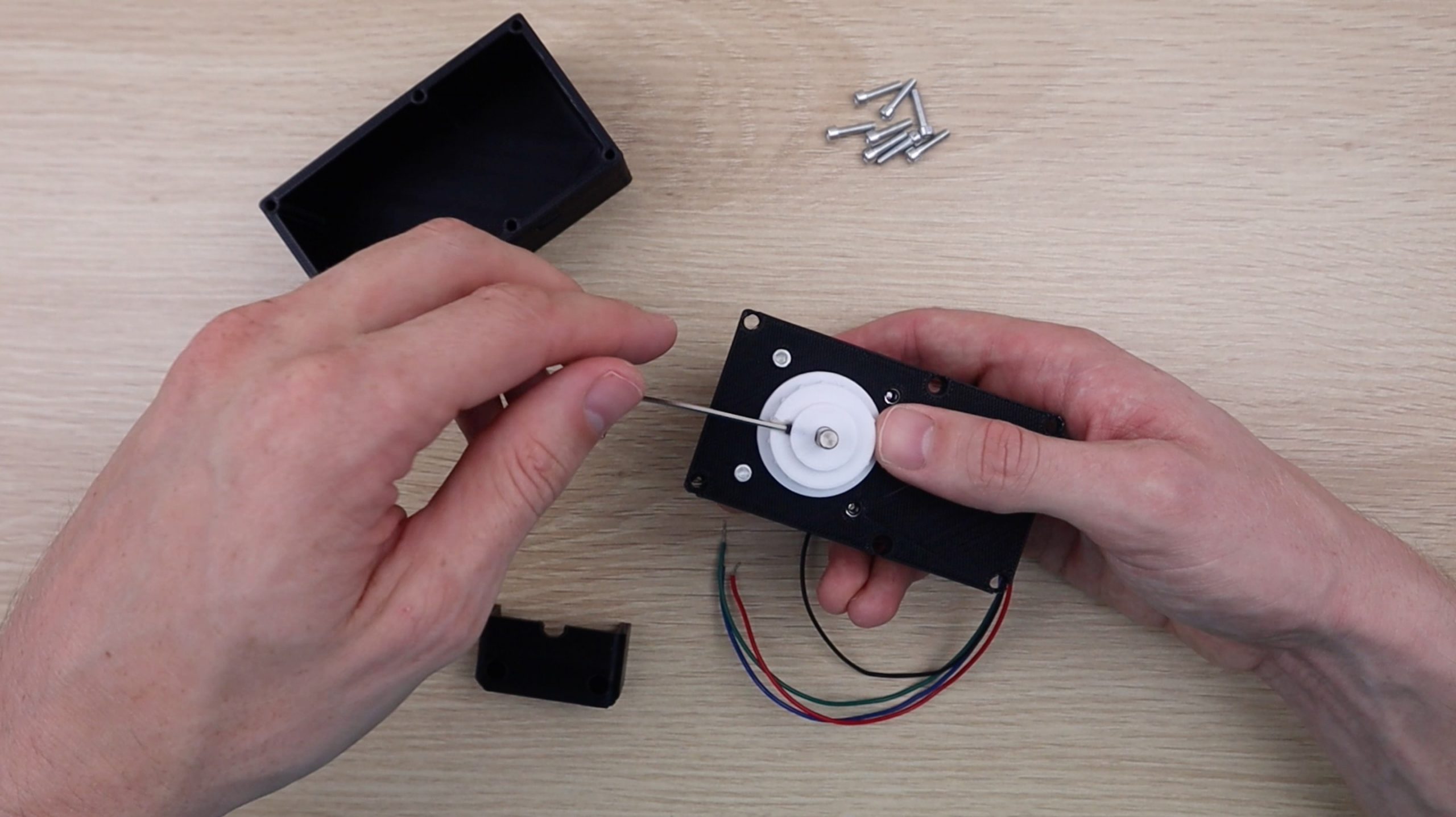
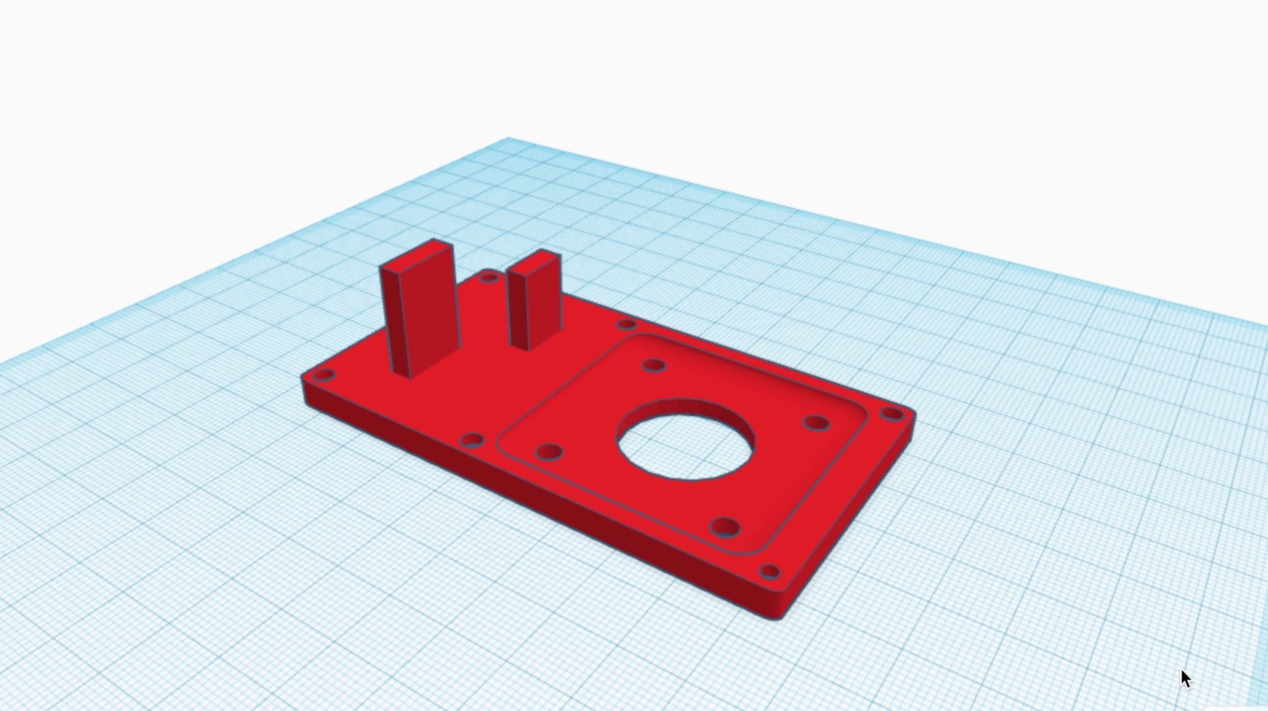
Start by mounting the motor onto the front cover using two M3 x 8mm screws in the top two holes.
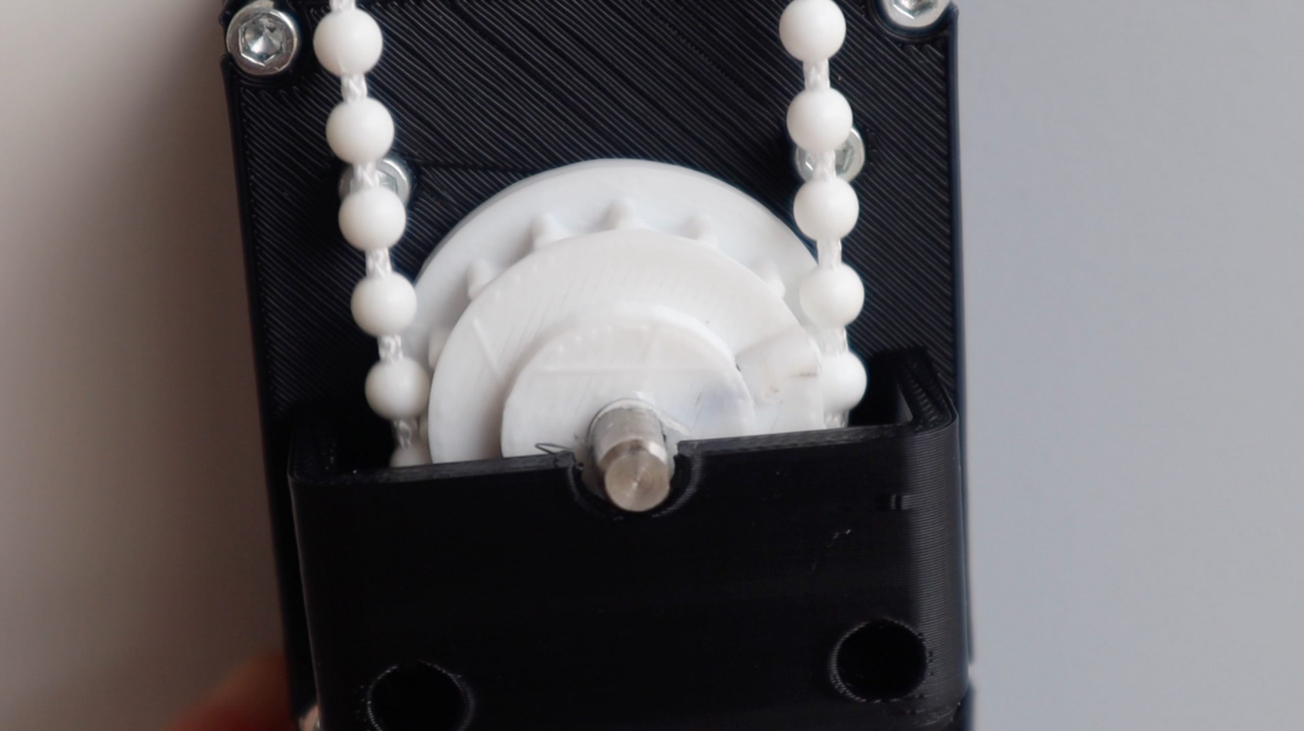
You may need to modify the the gear if your chain is spaced differently or if your motor shaft is a different diameter. Secure the gear using a M2 grub screw which sits on the flat side of the motor shaft.
Now put the gear cover on and use two M3 x 15mm screws through to the motor to hold it in place.
The front cover screws onto the back with more M3 x 15mm screws. I’ve put it together here to check that everything fits correctly, you won’t need to do so until you’ve put your electronic components together.
Solder The Wiring Harness
There are not a large number of connections to be made to the Arduino, so you only need to use the terminals down the one side. I decided that it would be easier to connect all of the components together using some ribbon cable and female header strips rather than destining a PCB. This also makes it easier for others to replicate the project without having to try and get PCBs made up.
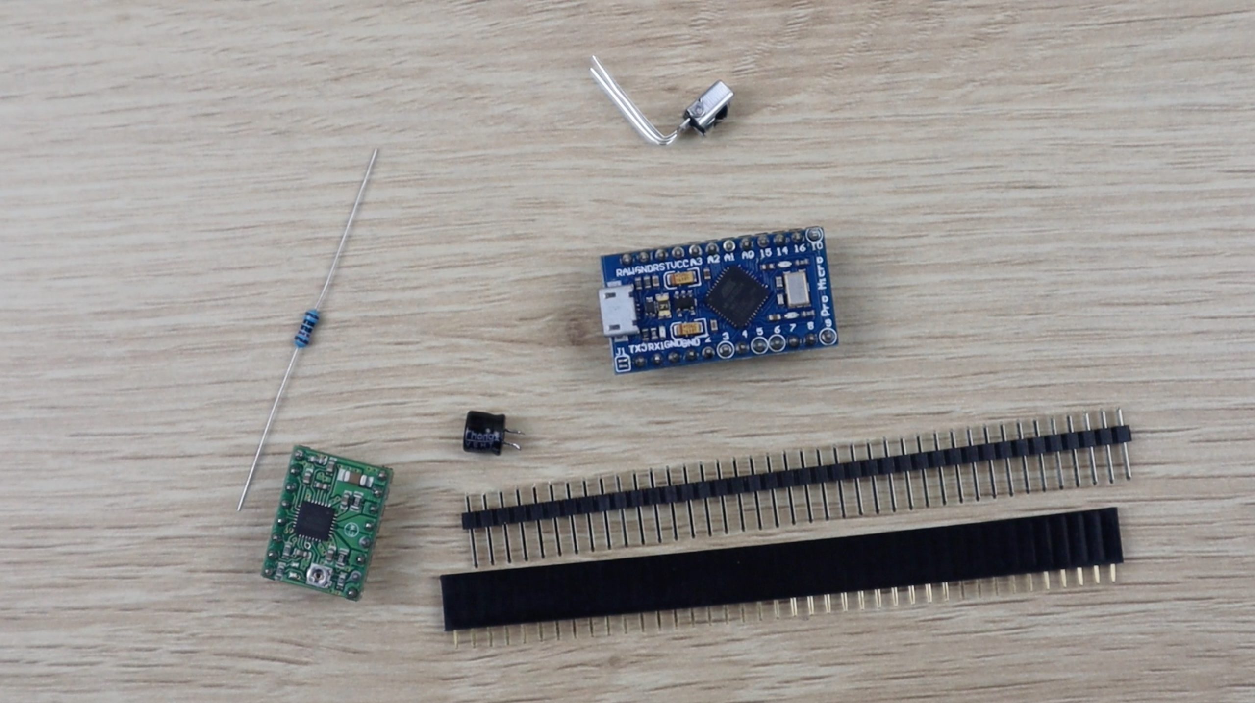
In addition to your Arduino and stepper motor driver, you’ll need an infrared receiver, a 10K resistor and a 100 micro farad capacitor.
Here is the schematic:
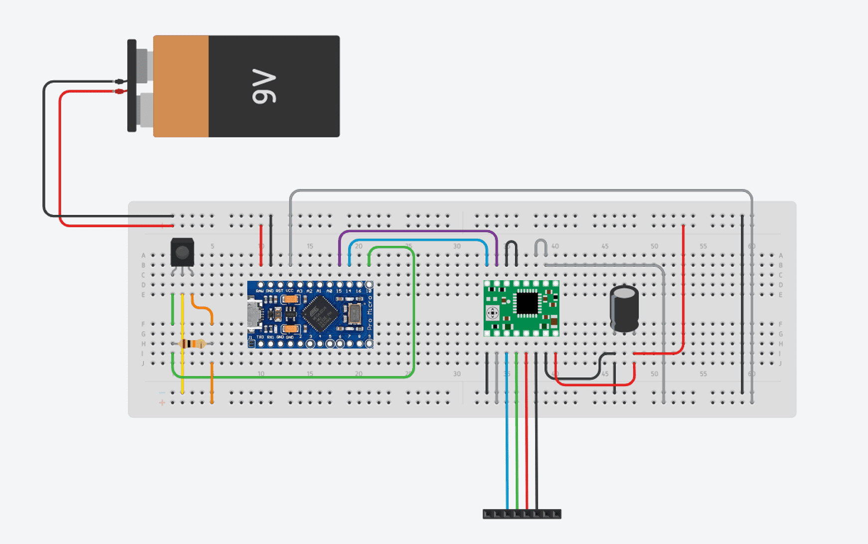
The resistor goes across the infrared sensor’s 5V and data pins and the capacitor across the power supply to the stepper motor driver. You can use a supply voltage between 5 and 12 volts, but a higher voltage produces power from the motor. The motor drive will accept up to 36V, but you can’t go above 12V with this format as the Arduino Pro Micro is limited to a 12V supply voltage.
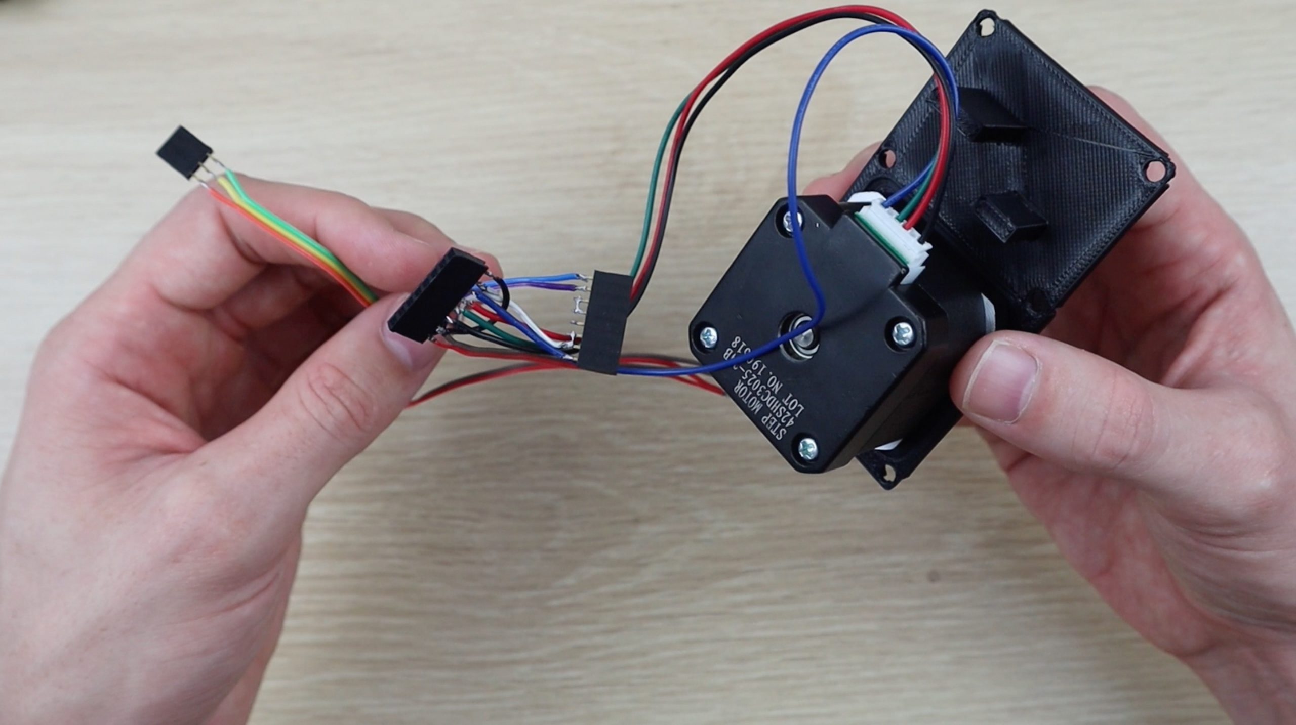
The connections to the sensor and boards are all made on sections of header strips which are cut to size according to the components. You’ll need two 8 pin strips for the stepper motor driver, one 12 pin strip for the Arduino, as you’re only using pins on one side, and one 3 pin strip for the infrared sensor.
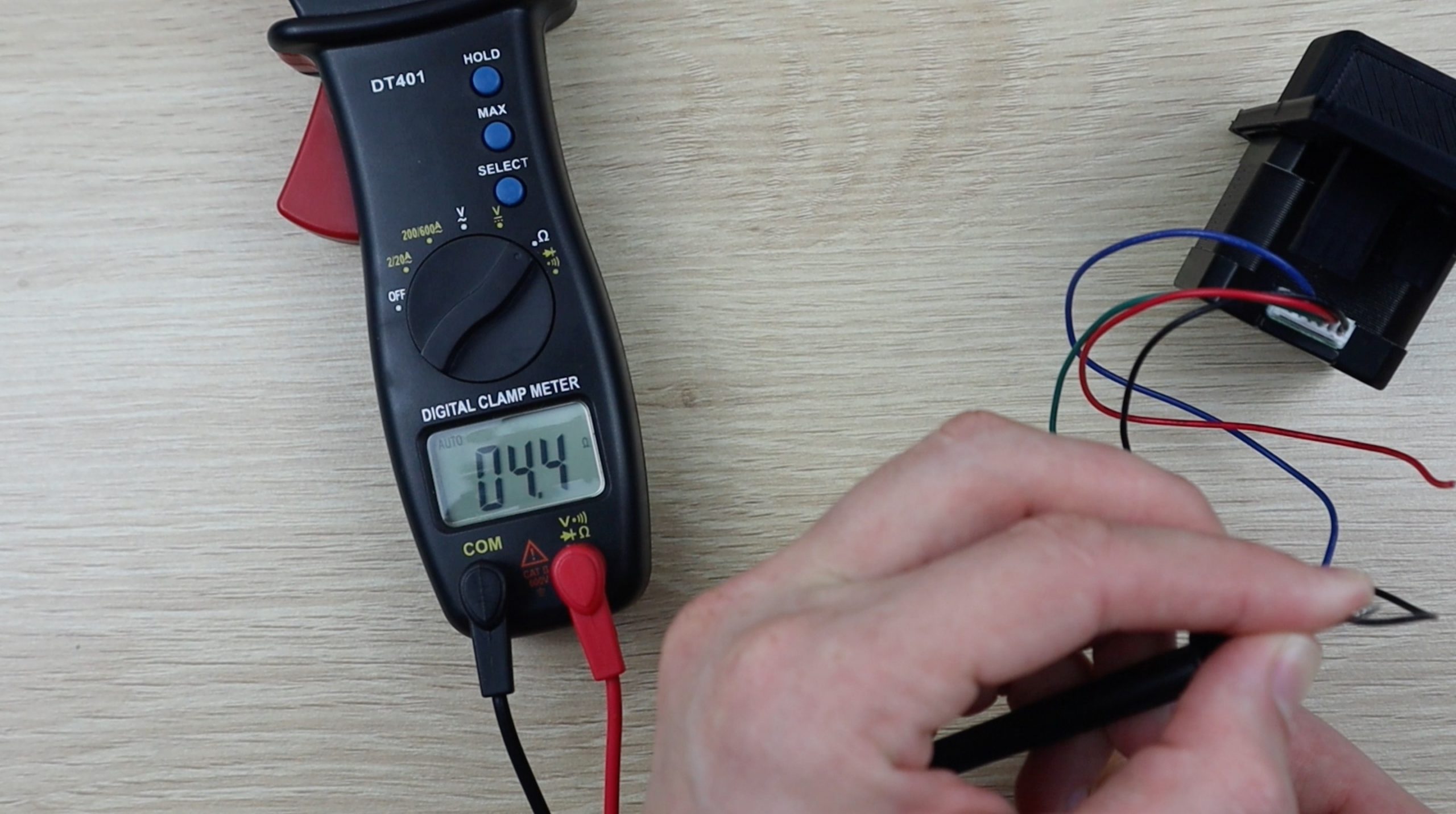
You’ll need to figure out which of the stepper motor leads belong to each of the two coils in order to connect them to the driver terminals. If you’re not using the same motor as I’ve used, use a multimeter to measure the resistance across each wire pair. The pairs associated with each coil should read about 4-5 ohms (this figure is usually on the motor data sheet as well) while you should get a mega-ohm reading for the other combinations. On this motor, one coil is connected to the blue and black leads and the other to the green and red.
Once your wiring harness is complete, you can connect it to your motor.
There is one more thing to set up before powering up your Arduino. You need to set the motor current limit on the driver. To do this, you’ll need to power up the driver, which can be done by supplying 5V to the logic circuit using the supply from your Arduino.
Then calculate your reference voltage using the following formula.
V(ref) = I(mot) x 8 x R(sen)
Your reference voltage is calculated by multiplying your motor’s maximum current, by 8 and then by your driver’s current sensing resistance. Your motors maximum current can be found on its data sheet, ours is .9 amps. The drivers current sensing resistance is .068 ohms for most newer drivers. You can find more information on using these motor drivers and setting them up properly here – Using An A4988 Motor Driver With An Arduino.
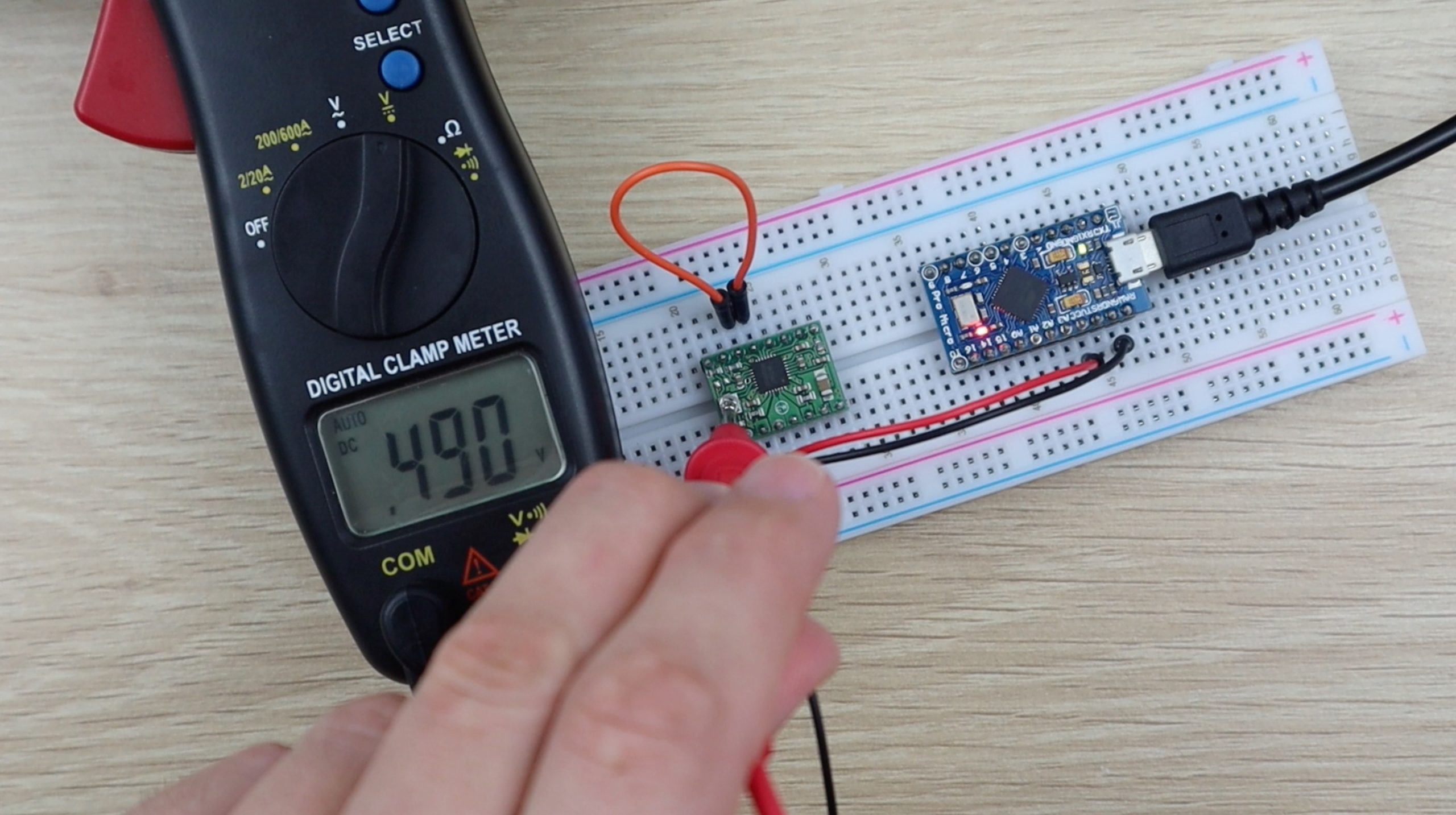
Using this formula, we calculate that our reference voltage should be about 0.49V.
This voltage is measured and set on the pot on the bottom of the motor driver using a small screwdriver to make the adjustments.
Start by measuring the reference voltage using your multimeter. Then make small adjustments, clockwise to increase and anticlockwise to decrease the voltage until this matches your calculated reference voltage. If you have clips on your multimeter leads, clip the positive on onto the metal part of your screwdriver and you’ll be able to see the voltage change and you adjust the pot.
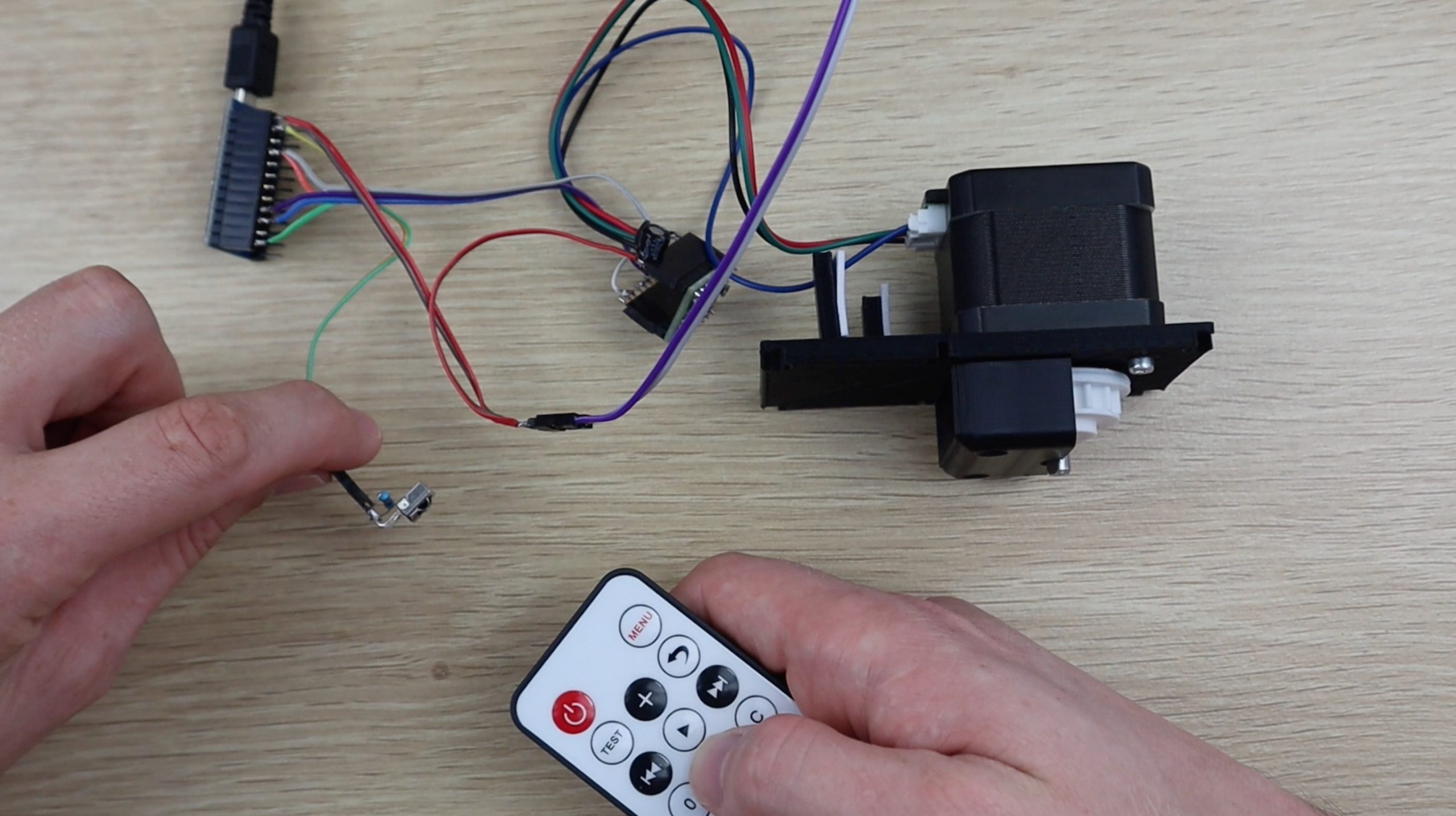
Once your current limit is set, you’re ready to power up your Arduino and upload the code. Connect your boards, stepper motor and IR receiver to your wiring harness and plug it into your computer to upload the code.
Upload The Code To Your Arduino
Here is the final version of the Arduino Automatic Blinder Code which I have uploaded to my Arduino:
//The DIY Life
//Michael Klements
//26 March 2020

#include <IRremote.h>

int iRPin = 10;            //IR sensor connected to Pin 4
IRrecv irrecv(iRPin);     //Create an IR object of the class
decode_results results;

int stepPin = 15;      //Define stepper motor step pin
int dirPin = 14;       //Define stepper motor direction pin

int blindDir = 0;         //Reverse default up direction if needed
int blindLength = 80000;   //Number of steps for full blind length
int blindPosition = 0;    //Initial blind position, 0 is fully open
int blindSpeed = 1;     //Delay between pulses, smaller delay, higher speed

void setup()
{
  Serial.begin(9600);       //Only used to get HEX value for each button
  irrecv.enableIRIn();        //Start the IR receiver
  pinMode(stepPin, OUTPUT);   //Define the stepper motor pins
  pinMode(dirPin, OUTPUT);
}

void loop()
{
  if (irrecv.decode(&results))  //Wait for an IR signal to be received
  {
    Serial.println(results.value, HEX);   //Only used to get HEX value for each button
    driveMotor(results.value);    //Change the LED accordingly
    irrecv.resume();             //Wait for next signal
    delay(200);
  }
}

void driveMotor(unsigned long value)  //Function to read the IR code and decide what the motor should do
{
  switch (value)  //Determine which button has been pressed
  {
    case 0xFF02FD:    //Button + Pressed - Open Slightly
      if (blindPosition >= 2000)
      {
        moveMotor(0,2000);
        blindPosition = blindPosition - 2000;
      }
      break;
    case 0xFF9867:      //Button - Pressed - Close Slightly
      if (blindPosition <= blindLength-2000)
      {
        moveMotor(1,2000);
        blindPosition = blindPosition + 2000;
      }
      break;
    case 0xFF6897:      //Button 0 Pressed - Open Fully
      moveMotor(0,blindPosition);
      blindPosition = 0;
      break;
    case 0xFF30CF:    //Button 1 Pressed - Close Fully
      moveMotor(1,blindLength-blindPosition);
      blindPosition = blindLength;
      break;
    case 0xFF18E7:      //Button 2 Pressed - Blind Preset 2 (1/4 Closed)
      if (blindPosition > blindLength/4)
      {
        moveMotor(0,blindPosition-(blindLength/4));
      }
      else if (blindPosition < blindLength/4)
      {
        moveMotor(1,(blindLength/4)-blindPosition);
      }
      blindPosition = blindLength/4;
      break;
    case 0xFF7A85:      //Button 3 Pressed - Blind Preset 3 (1/2 Closed)
      if (blindPosition > blindLength/2)
      {
        moveMotor(0,blindPosition-(blindLength/2));
      }
      else if (blindPosition < blindLength/2)
      {
        moveMotor(1,(blindLength/2)-blindPosition);
      }
      blindPosition = blindLength/2;
      break;
  }
}

void moveMotor(int moveDir, int noSteps)  //Function to move the motor in direction moveDir and number of steps noSteps
{
  if (moveDir == blindDir)
    digitalWrite(dirPin, HIGH);
  else
    digitalWrite(dirPin, LOW);
  for(int i=0 ; i<=noSteps ; i++)
  {
    digitalWrite(stepPin, HIGH);
    delay(blindSpeed);
    digitalWrite(stepPin, LOW);
    delay(blindSpeed);
  }
}
Download the code – Blind Opener Code
The code makes use of the IRRemote library for the infrared sensor inputs, creating an infrared object with pin 10 as the sensor’s input pin.
The stepper motor driver is connected to pins 14 and 15 to control the direction and provide the pulse signals respectively.
We then have a couple of parameters for the blinds which will need to be adjusted.
The first is for the blind movement direction, with zero being the default and 1 being reverse. You’ll need to test this out on your blinds to make sure that when you push the down button, the blinds close and visa versa.
The second is the blind length, which is the numbers of motor pulses to drive the full length of the blind. You can calculate this by equating the motor pulses per revolution (taking into account the motor driver mode) to the number of balls on the gear and then to actual blind movement. The easiest would be to use the default as a starting point, see how far it moves up or down and then adjust it accordingly.
The next parameter is the blind’s initial position, 0 being fully open. This doesn’t really need adjustment, unless you want to “power on” with the blinds closed rather than open. It’s important to note here that the opener remembers the blind position based on the number of pulses given, so if the power to your Arduino is interrupted, you’ll need to reset the blind position to the correct initial position before operating it again. You could overcome this by installing a limit switch at the fully open or closed positions for calibration but this would involve extra wiring external to the actual opener, which I wanted to avoid.
Finally, the blind speed which is essentially the the motor speed, a lower number is a shorter delay between pulses, which is a faster speed.
You can also increase the motor speed by changing the delay to microseconds instead of milliseconds or running the driver in full step or quarter step modes. Full step mode would be the fastest.
In the setup function we start the serial communication. This is initially used to get the infrared codes from your remote in order to add them to the code and can be commented out once you’ve done this. We then start the infrared receiver and assign the motor driver output pins.
The loop function waits for a single to be received from the infrared remote, then displays it on the serial monitor. This can also be commented out after setup. The driveMotor function is then called to drive the motor before waiting for the next infrared signal. The delay is just added for stability.
The drive motor function gets the infrared signal as an unsigned long variable type. A switch statement then decides what the motor should do based on the signal received. The hex codes in this section need to be changed according to what was shown in your serial monitor when you push the corresponding button on your own remote. You can use the remote which came with your sensor or an old TV remote or a universal remote, as long as your Arduino can read the signal from it.
You can decide what you’d like to be able to do with the remote control, I’ve set up the up and down arrows on my remote to open or close the blinds in small increments, allowing me to position them as I’d like. I’ve then set up the 0 and 1 buttons to fully open or fully close the blinds and I’ve got two more presets, one for 1/4 of the way closed and one for 1/2 way closed. You could set up as many presets as you’ve got available buttons on your remote.
Each case in the switch statement decides on the motor movement based on the blinds current position and the desired position and then tells the motor how to move by calling the move motor function, giving it a direction and number of steps.
The move motor function then sets the direction on the motor driver and generates the pulses to the motor.
It’s a good idea to test this out, get your code working properly and make any adjustments to travel limits before putting the electronics into the housing.
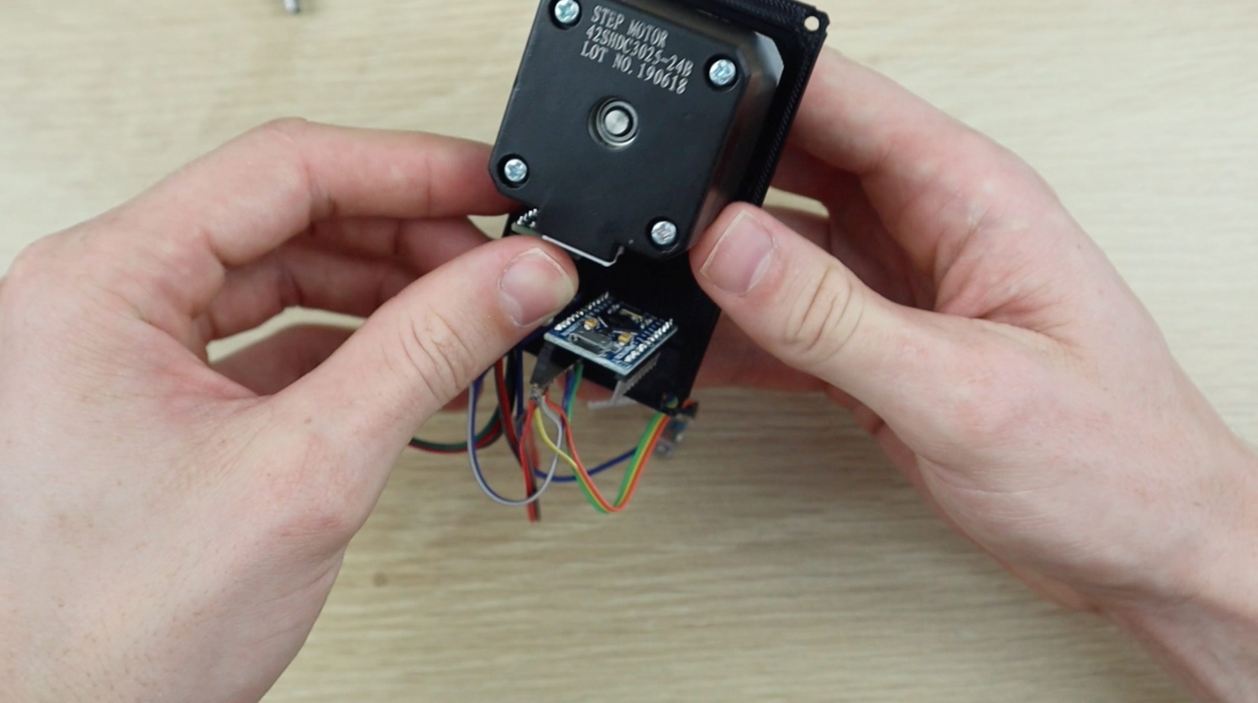
Once you’re happy with the code, stick the Arduino and motor driver to the supports on the housing using double sided tape. Don’t forget to add your heatsink to your motor driver too. Don’t worry about needing to make adjustments to your code, the USB port on your Arduino is still accessible with it stuck in place.
The IR sensor gets stuck into the aperture in the side of the back part of the housing. This is why we have a header strip on it, so that it can be disconnected from the electronics mounted to the front cover to attached it to a wall or frame.
You can now upload the final version of your code and close up the housing.
Using Your Arduino Automatic Blind Opener
I haven’t put any holes into the housing to mount it as there are a number of different ways this automatic blind opener could be mounted and I didn’t want the housing to be full of spare holes. The most simple would be to use two screws through the back or sides of the housing. You should be able to mount the back of the housing using one of the back or side faces and then screw on the front face with all of the electronics, so that the screws are no longer visible. You can drill holes through the back or sides, the best would be to add the holes to the model before 3D printing it.
Once the opener is mounted, use your remote control to open and close your blinds using the buttons which have been set up in the code. You should be able to open or close the blind in small increments as well as press a button for fully open, fully closed, 1/4 open and 1/2 open positions.
Have a look at the video in the introduction for the Automatic Blind Opener in action.
I may look at trying to dampen some of the sound from the stepper motor with a rubber pad in future, as it is quite noisy when running.
Use Your Automatic Blind Opener With A Smart Home Device
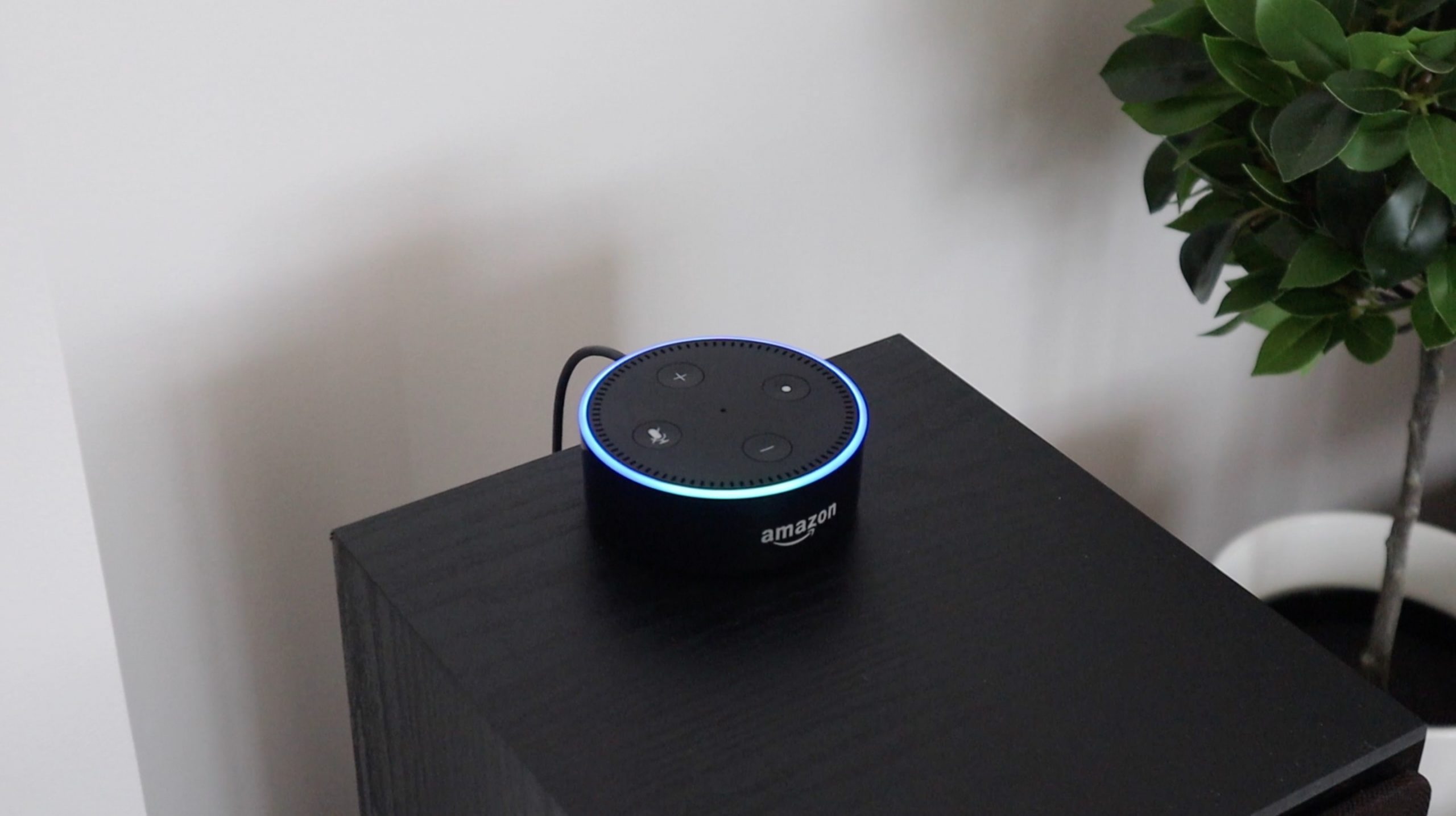
One of the great things about controlling your Automatic Blind Opener using an IR remote is that you can use a smart home universal remote to operate it as well. This allows you to open and close your blinds using voice commands through an Amazon Echo or Apple Home Pod or set up routines to automatically open and close your blinds at certain times in the day.
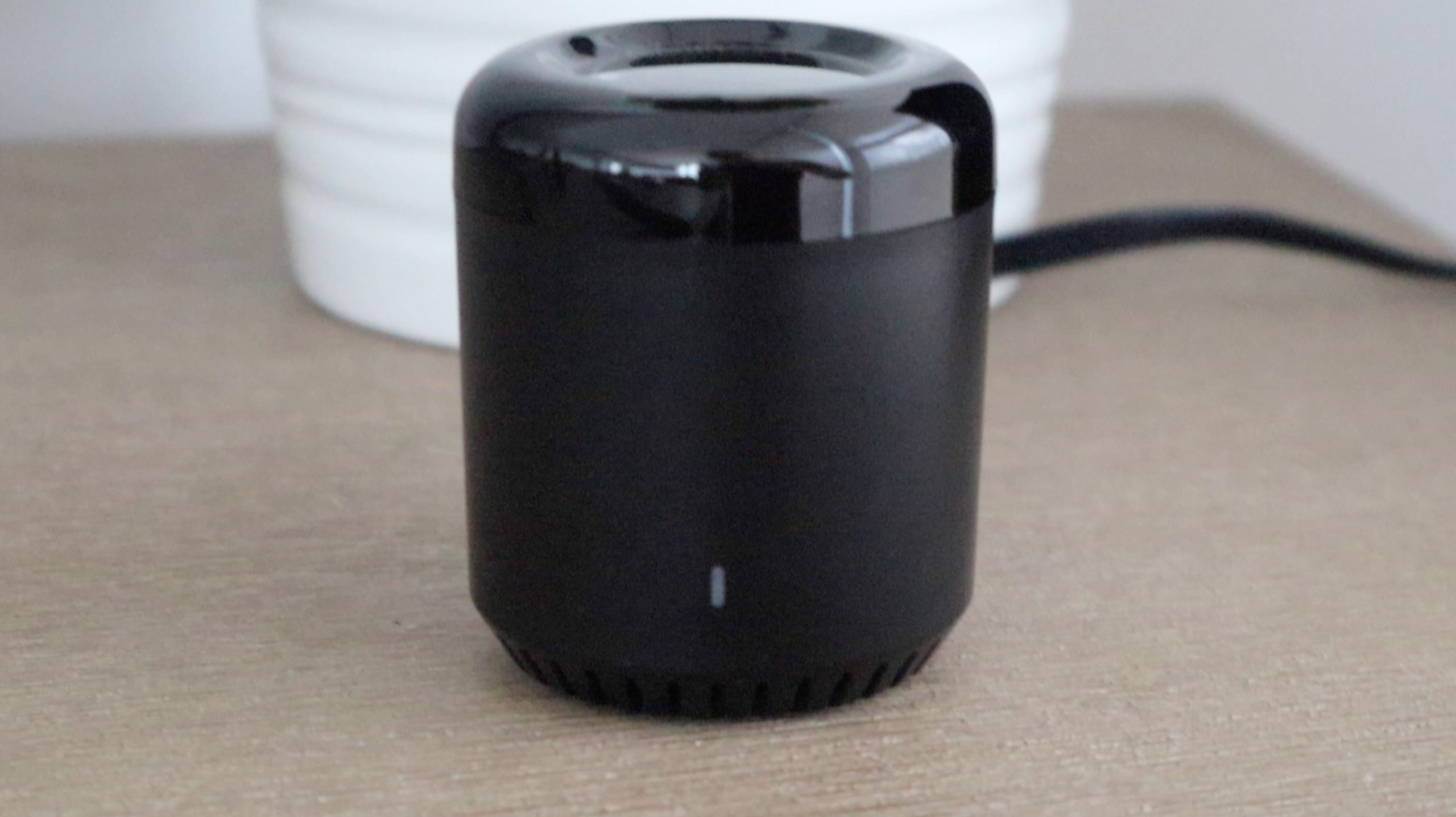
To operate your opener with an Alexa enabled amazon device, you’ll need a smart home universal remote like this RM Mini 3 which is linked in the parts list. The RM Mini 3 is not the best smart home remote control but it is quite cheap and easy to use.
If you do get this remote control, use the Intelligent Home Centre app (not the one in the user manual) to teach the remote the signals from your existing remote and you’ll then be able to add these commands to your echo devices and integrate the opening and closing of the blinds into your routines or using timers.
Good luck with this project and le us know what functionality you’ve added or changes you’ve made in the comments section below.
Hello, I did the project but the motor is not strong enough to operate the roller. It stays blocked. I have used the Nema 17 motor from Torque 1.8 which is the closest thing I have found. Could you tell me the exact number of the engine you use? Thanks
I used a salvaged motor from an old 3D printer, so I don’t have a datasheet for it. The motor’s ability to lift the blind depends quite significantly on the design of the blind though – how wide, long and heavy it is, as well as how well the mechanism works. You should be able to just find a stronger stepper motor though.
I love this project and can’t wait to get started on mine.
The only thing I don’t see is how you power it once everything is closed up.
Mine is powered with a 9V wall adaptor connected as shown in the circuit diagram. I just made a small hole for the cable between the joins in the case.
Do you have a cad drawing or similar as I think the cog will not fit my cord ?
Hi, is the gear also printable in the same file or did you got it from elsewhere?
I 3D printed the gear as well
Thank you very much for your answer. I did take ur file but didn’t get the chance to open it 🙁 . Thank you once again ?
Thank you very much for your answer. I did take ur file but didn’t get the chance to open it 🙁 . Thank you once again ?
Hello Michael ,
Need your help , i get the following error verifying the Sketch
Arduino: 1.8.19 (Windows 10), Board: “Arduino Uno”
BlindOpener:5:10: fatal error: IRremote.h: No such file or directory
#include
^~~~~~~~~~~~
compilation terminated.
exit status 1
IRremote.h: No such file or directory
This report would have more information with
“Show verbose output during compilation”
option enabled in File -> Preferences.
I figured it out !!!! 🙂
Hello,
First of all, thanks for sharing all this, great way to practice my soldering which i’ve neglected in the past ^^
My blinds have very small beads so i’ll have to change it.
I was wondering what you suppose is the easiest way to modify the gear to be spaced differently.
Is it possible to have the model files?
Kind regards,
Thomas
Hi Thomas,
Unfortunately I made this case and gear in Tinkercad, so it’s not really useful for editing or making changes to it. You’ll probably need to design a new one to suit your bead size.
Hello sir,
First of all I would like to thank you for sharing your project with us.
I need your opinion and (if it’s possible) your help to adding limit switches to your code.
I’m using the codes for the my DIY TV lift project (believe me or not NEMA 17 can lift up 6 kg. TV easily:)) but and of the day I need to stop the motor with switches for security. (In case of power loss I have to disassemble everything)
I tried a code with limit switches but I don’t know why it’s fried my arduino’s power regulator chip.
I will be appreciated if you help me.
Sincerely, Kaan.
Hello Michael,
Thanks for posting this project, it has given me a better start then most i have seen!
Just one (maybe 2 questions)
How hard is it to convert you code to use a webserver type function to be able to connect to Alexa? I am trying to accomplish this by not spending a great deal more on parts and would like to forego the remote control and just have Alexa( or google) to open my vertical blinds at 7am and close them at say 5pm.
I cannot for the life of me find a tutorial to aid me in this as yet as they are all one way or another way.
Im hoping you can help me
Thanks in advance
Mark
Could someone make a version for Arduino nano pls?