I’ve designed this simple Arduino based automatic colour sorter which allows you to easily sort Skittles, M&Ms and other small coloured candy. Simply fill up the hopper and switch it on to sort your Skittles into five plastic test tubes. The sorter uses a cheap TCS34725 colour sensor module and a decision tree algorithm to sort the Skittles.
I’ve designed a few basic 3D printed components which you’ll need to print out in order to make your own sorter. The rest of the components are all widely available standard parts which I’ve linked in the materials list.
This guide assumes that you’ve worked with an Arduino micro-controller before and know the basics of programming an Arduino. If you do not, follow the linked guide for more information on creating and uploading your first sketch.
Here’s the video guide if you don’t feel like reading through the build:
What You Need To Build Your Own Arduino Based Skittles Colour Sorter
- Arduino Uno (Or Other) – Buy Here
- Arduino Power Supply – Buy Here
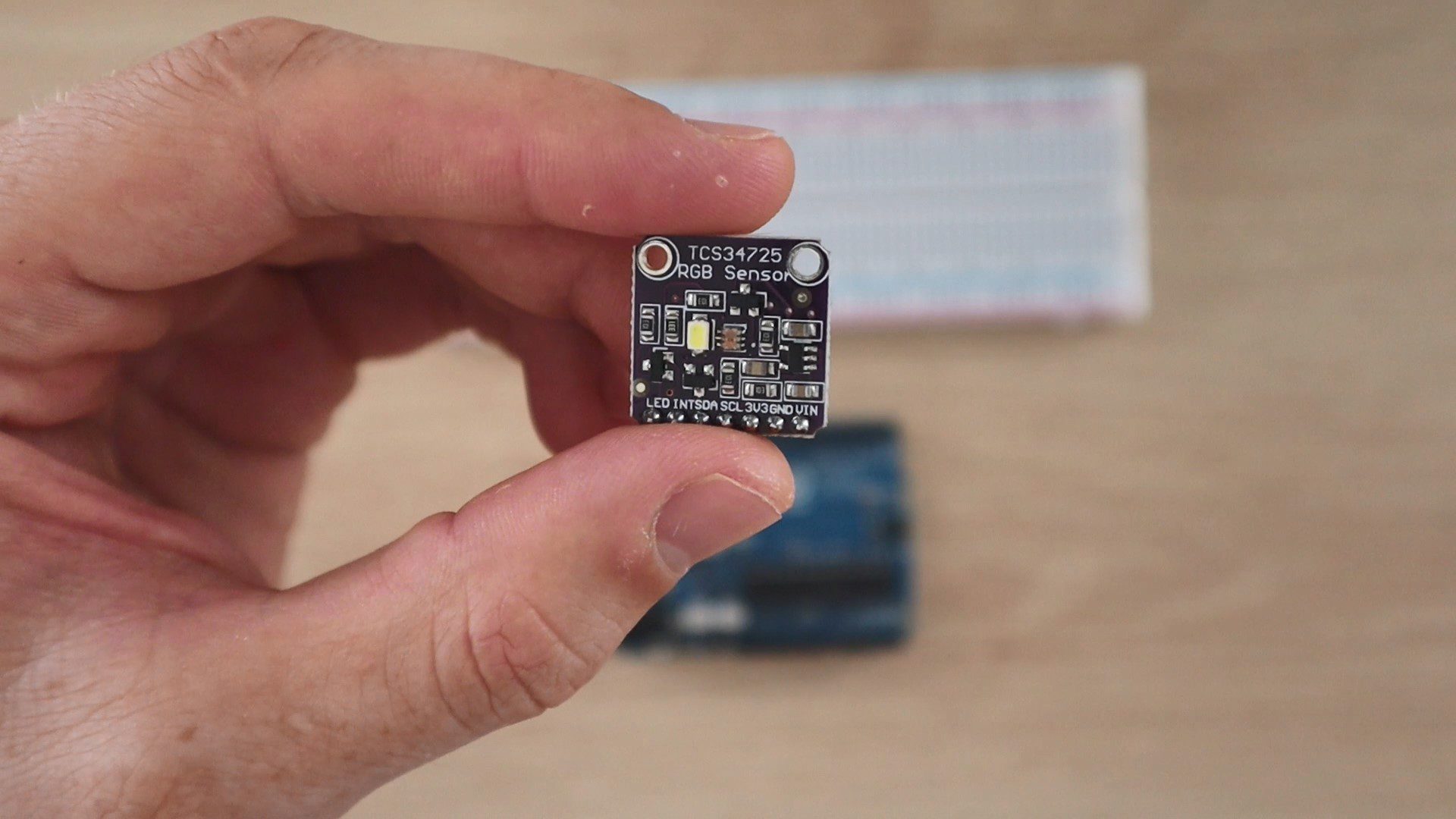
- TCS34725 RGB Sensor – Buy Here
- Breadboard & Jumpers for Testing – Buy Here
- 2 x Micro Servos – Buy Here
- 16mm Square Aluminum Tubing – Available at Hardware Stores – A Wooden Dowel Can Be Used As Well
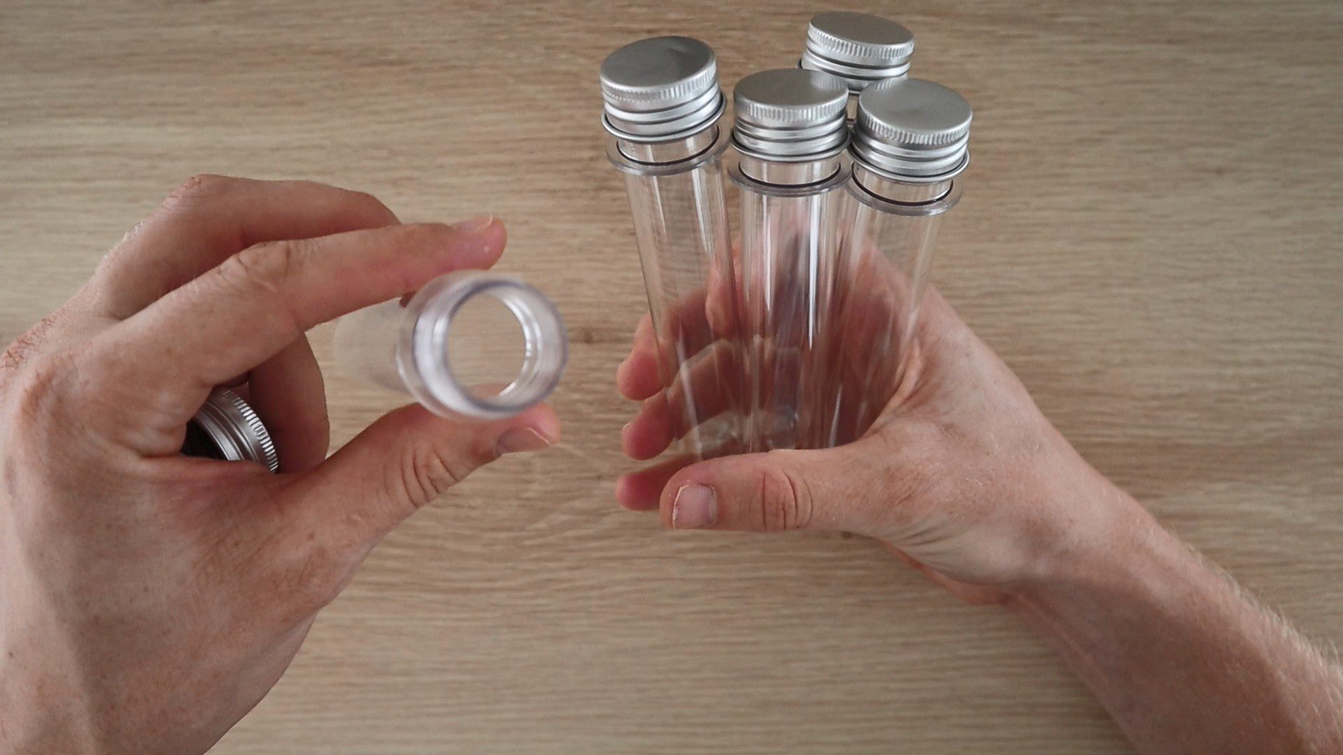
- 5 x Clear Plastic Test Tubes – Buy Here
- 3D Printer & White/Black Filament (Optional for Housing) – This One Used
- Skittles (For Calibration & Sorting) – Buy Here
In addition to these, you’ll need basic tools for working with electronics and a glue gun or epoxy adhesive to assemble the components.
Assembling the Arduino Based Skittles Colour Sorter
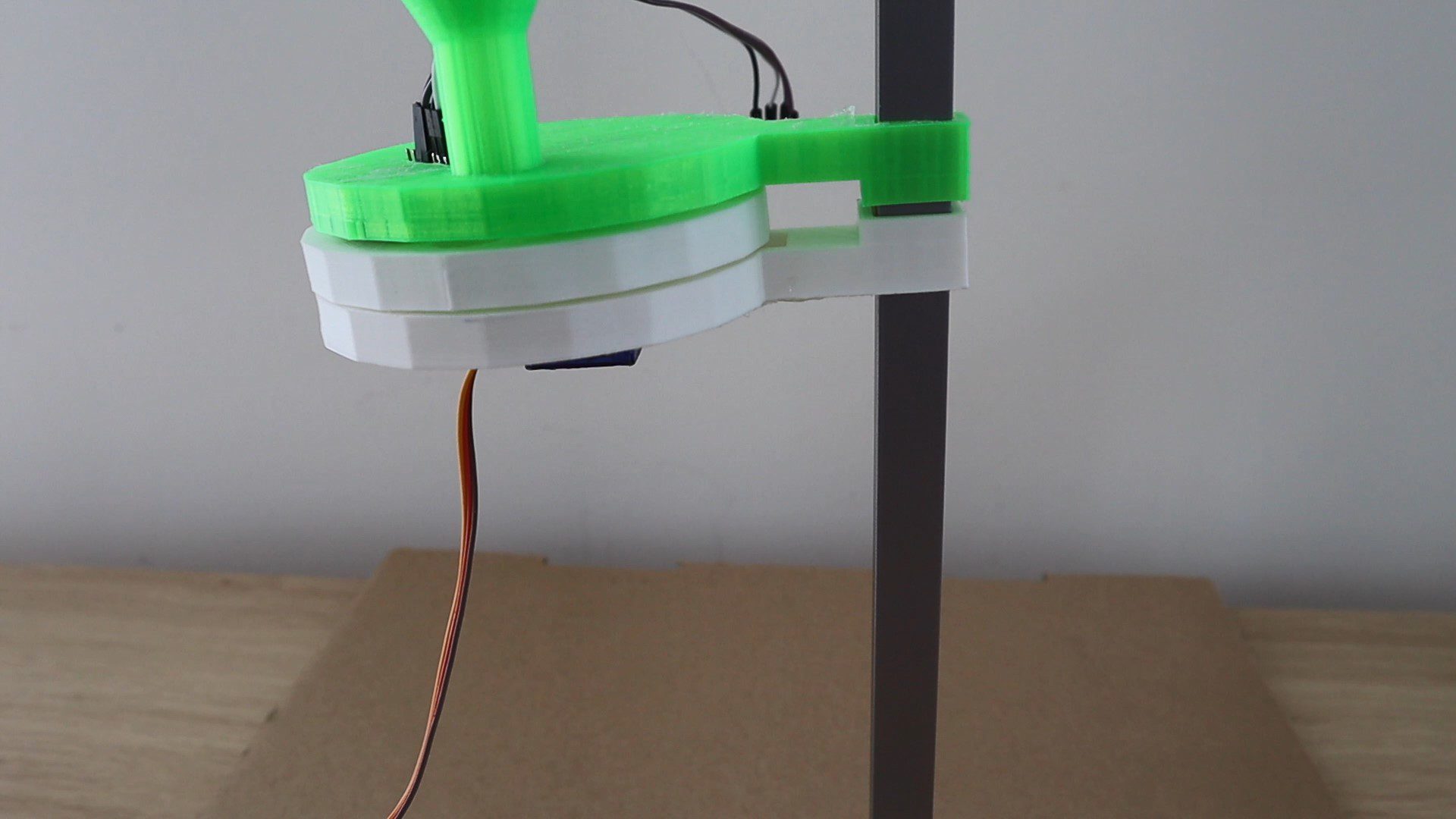
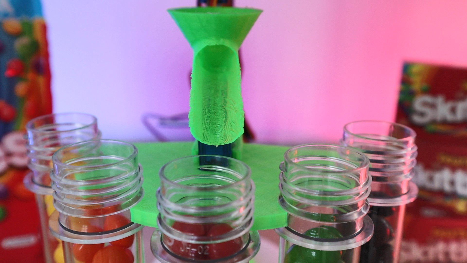
The sorter is designed as two separate assemblies, the selecting assembly which selects a Skittle from the hopper/funnel, moves it to the colour sensor for identification and then moves it on to a hole which allows it to drop into the sorting chute. The sorting assembly holds the sorting tubes in place and supports the servo driving the sorting chute to direct each Skittle into the correct tube.
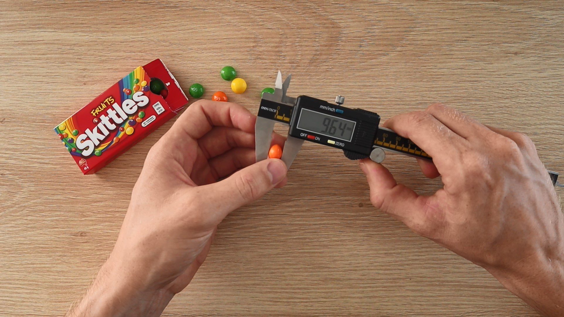
I have designed the selector and sorter assemblies to sort Skittles, so the components have been designed around the size of an average Skittle. But you can quite easily customise either of these assemblies to accommodate your own candy and make adjustments for materials which you may already have at home. If you’d like to sort M&Ms then you’ll need to add a 6th test tube, or you could change the test tubes for plastic cups if you already have them at home etc.
3D Print the Sorter Components
You’ll need to start off by 3D printing your components, the 3D print files can be downloaded here: Colour Sorter 3D Print Files
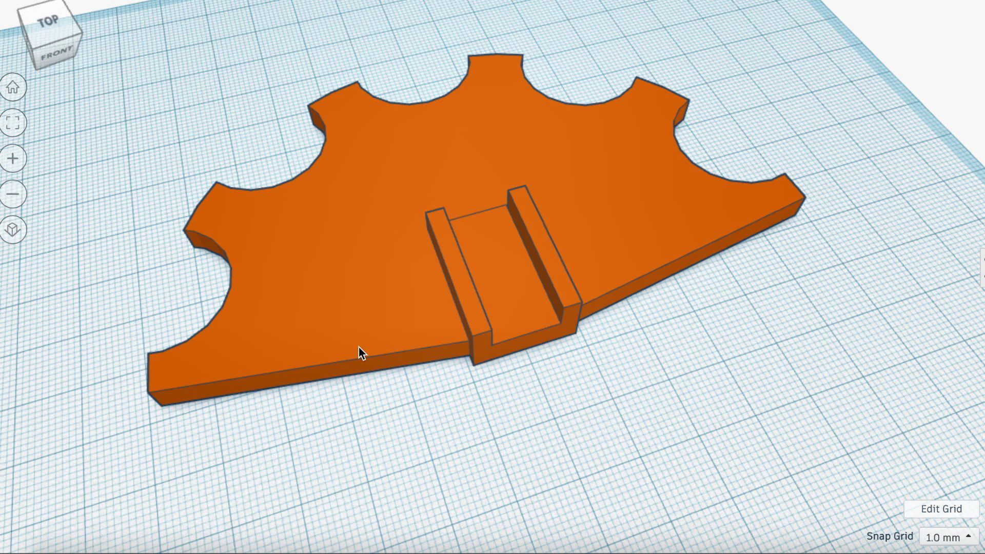
I used white and green PLA for mine and printed them at 15% infill. You can use any colours you like but I’d suggest using black, white or grey for the selector bottom and middle plates to avoid introducing reflected colour to your sensor module.
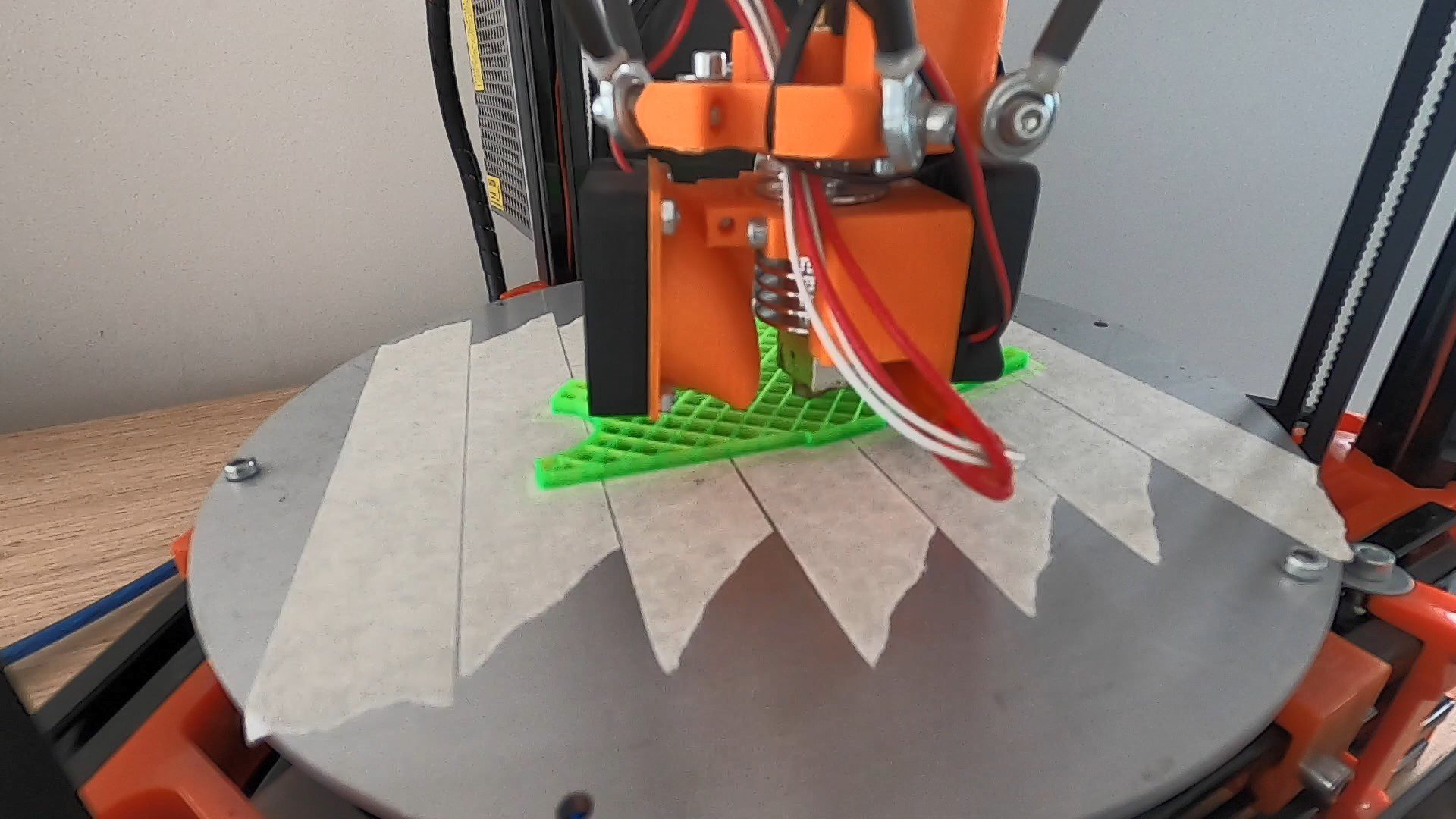
After 3D printing, make sure that you trim off or sand any stringy or warped areas and check that your Skittles are able to easily pass through the openings otherwise you’ll have continuous problems with Skittles getting stuck in the selector.
You’ll need a print bed of around 150mm (6”) to 200mm (8”) in order to comfortably print all of the components, the tube holders are the largest (longest) components in terms of lay-down area.
Assemble the Components
Once your components are 3D printed, you can begin assembling them.
Glue the two base pieces together and then insert your square tubing into the pocket in the base and glue it to secure it.
The tubes get glued into place on the top and bottom sorter pieces, you could also use a hook and loop cable strap to hold them in place if you’d like to be able to remove the tubes individually afterwards.
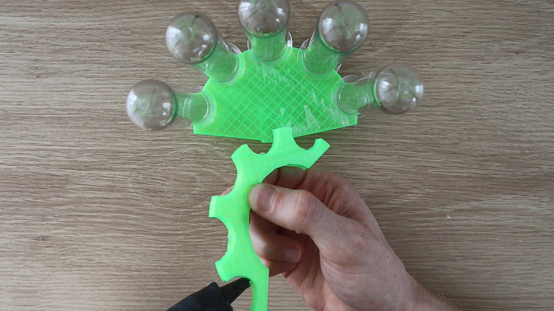
Then glue the servo arm into the pocket in the bottom of your sorting chute.
Finally, push the sorting chute onto the servo and glue the servo into place in the slot on the top sorting section. Try to ensure that your servo is in the middle of its travel range and that your chute is facing the centre tube. This isn’t critical as you can easily re-position the chute once your servo is powered up – see the calibration step at the end. Position it so that there is a small gap of about 3mm (0.1”) between the end of the chute and the centre tube. If you put it too close then your chute may catch on the tubes or the Skittles will overshoot the tubes and if you put it too far away then the Skittles will fall into the gap between the end of the chute and the tube.
Next you’ll assemble the selecting mechanism.
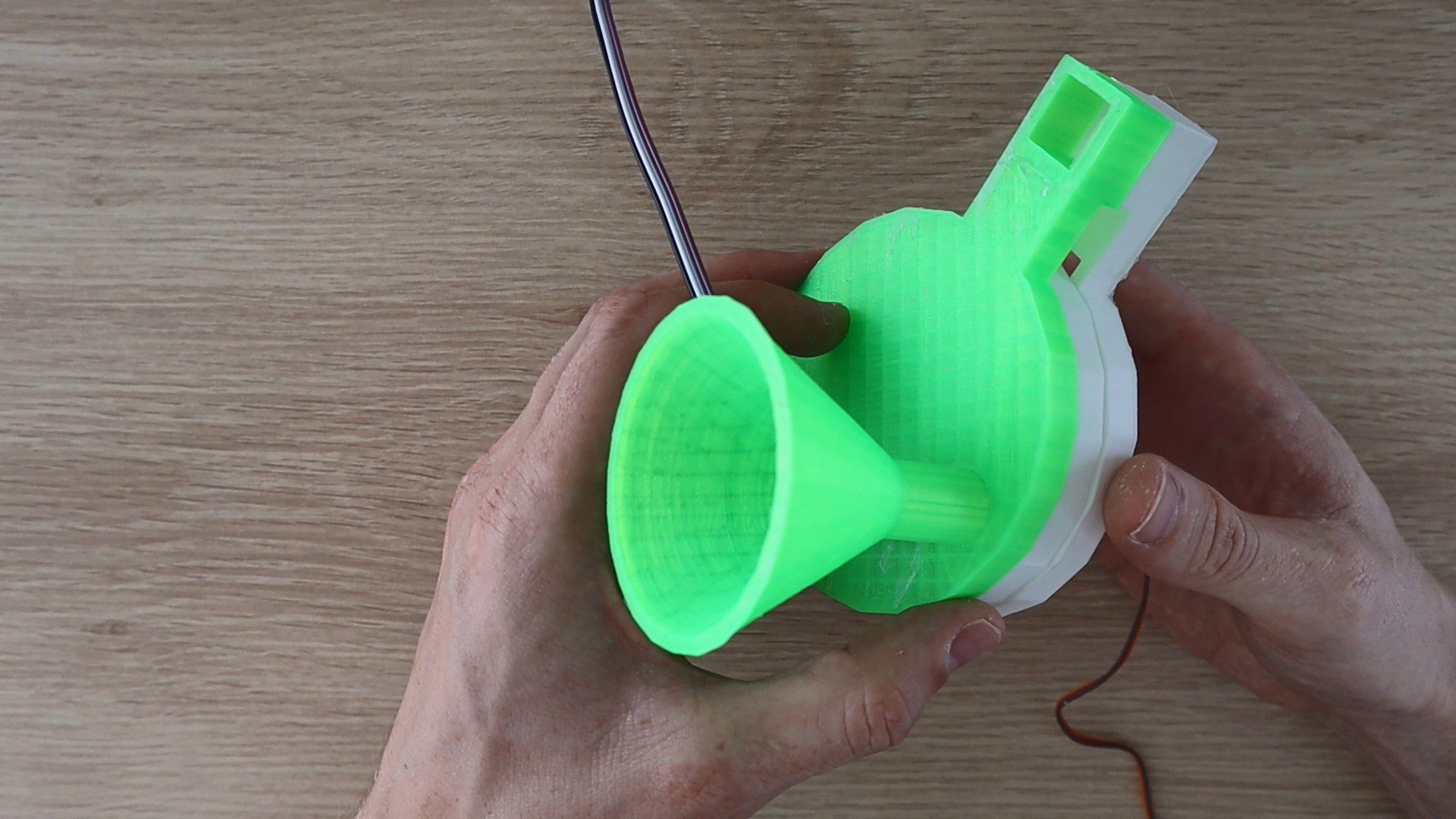
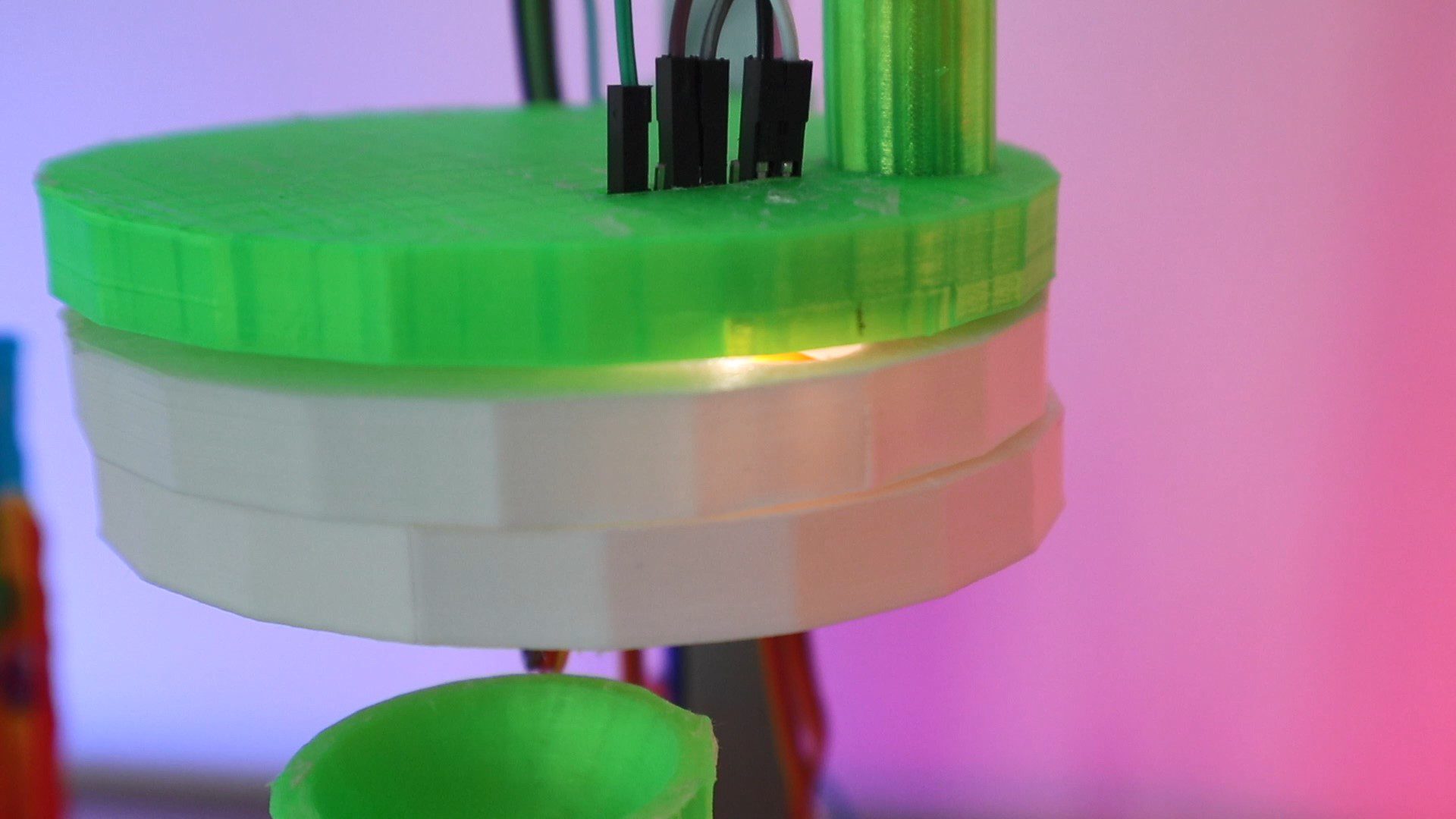
Push your TCS34725 RGB sensor into the recess in the top plate such that the pins stick out of the top of the plate. The recess should be a tight fit around the sensor so that you don’t have to glue it into place.

Plug your jumper leads into the pins on the back of the sensor module, then install the hopper/funnel.
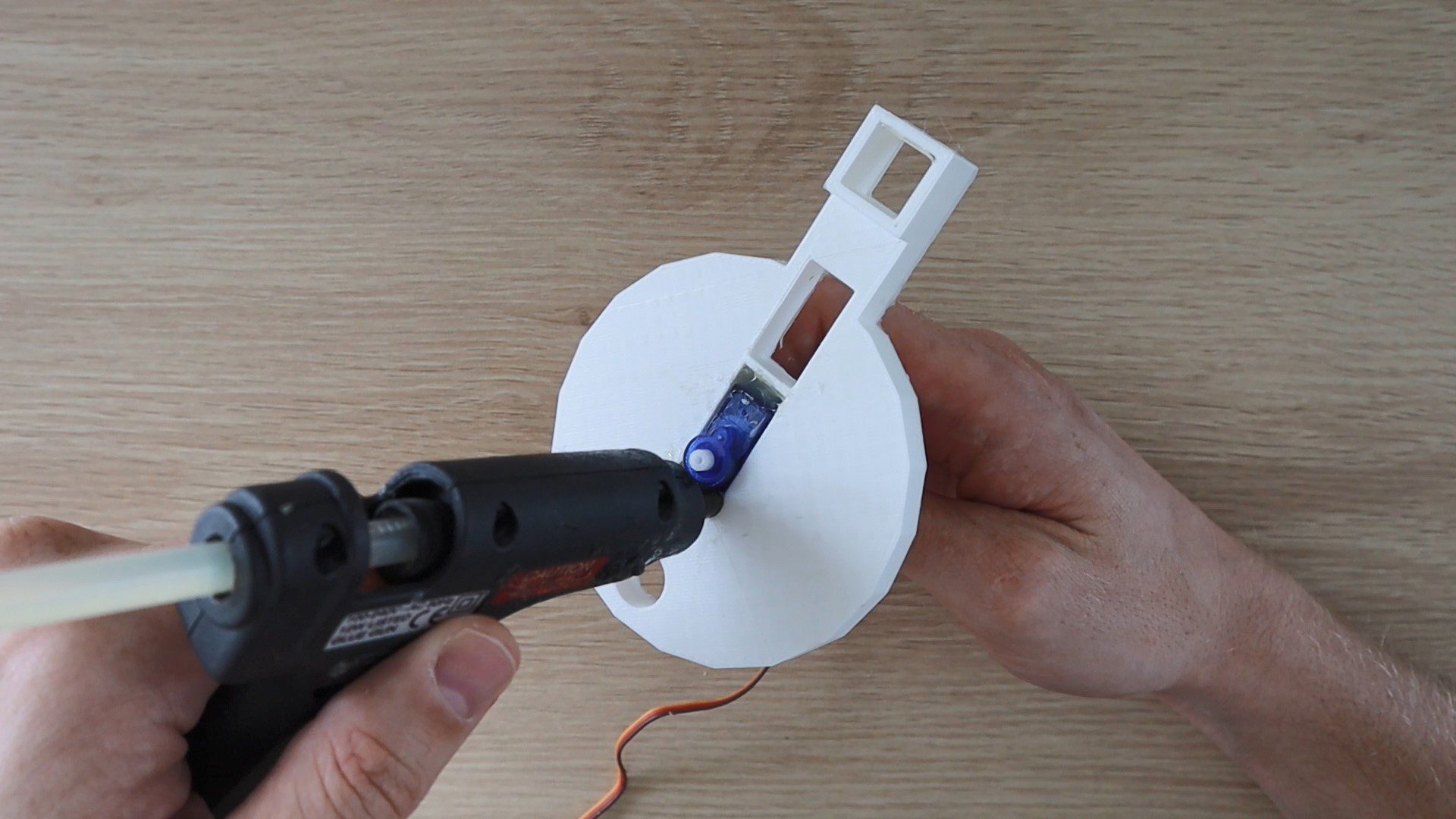
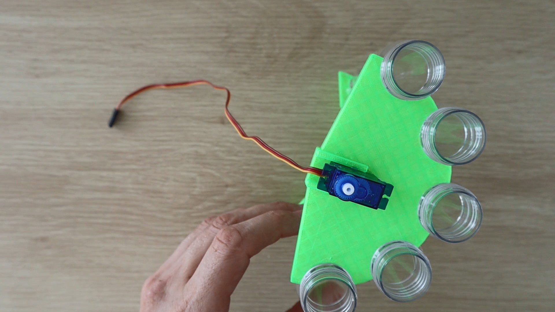
Glue the selecting servo into the cutout in the bottom plate so that the center or rotating point of the servo arm is in the center of the plate.
Next, glue the servo arm into the middle plate and then push the plate onto the bottom plate. Make sure that your servo is in the center of its range of movement and try to position the hole roughly where the colour sensor module will be. This way you’ll avoid having to re-position the disk once you’ve powered on the servo and found that the holes are out of the travel range.
Push all three plates onto the aluminium tube stand and position them so that there is a gap of about 15mm (0.6”) – 20mm (0.8”) between the bottom plate hole and the top of the sorting chute before gluing the bottom plate into place on the stand. Don’t glue the top plate into place as you’ll need to be able to open it up for calibration and troubleshooting.
Depending on how long your servo extensions are and where you choose to position your Arduino, you may need to add jumper extensions onto them in order to reach the pins.
Connecting the Skittles Colour Sorter Circuits
The connections to your Arduino for this project are quite straight forward, shown in the below diagram:
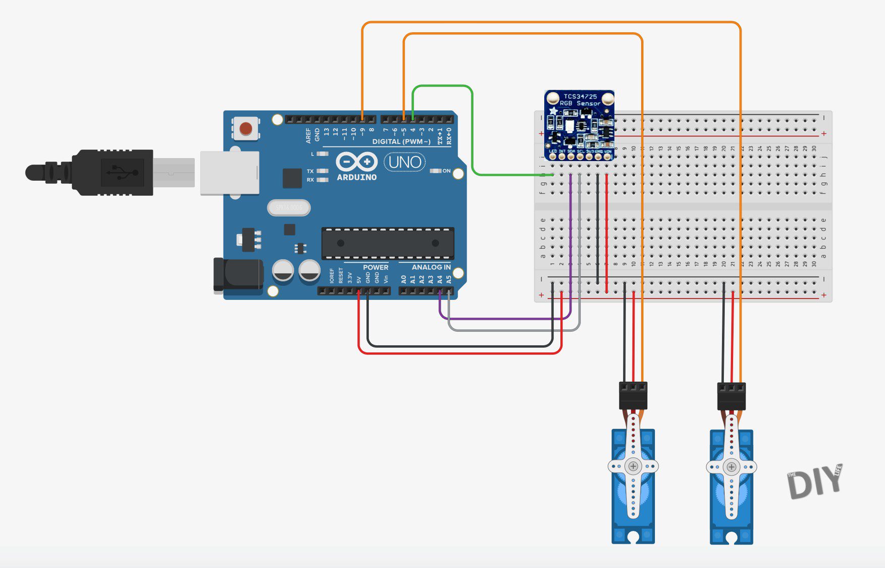
We’re simply connecting a servo for the skittle selector to Arduino Pin 5, another servo for the sorting chute to Arduino Pin 9 and then the colour sensor to your Arduino using the I2C interface on Pins A4 and A5 with an optional connection to Pin 4 to control the onboard LED (otherwise the LED just stays on permanently).
If you’re going to be using a different Arduino board, make sure that the I2C pins are correct as these are different on different boards. For example the Pro Micro uses Pins 2 & 3 for SDA and SCL respectively, not A4 and A5 as in this project on the Uno.
All 3 of the connections (the two servos and colour sensor) require a 5V supply. This is easy to connect using a breadboard as shown in the diagram. I made a small adaptor which plugs into the 5V and GND pins on the Arduino and expands them to 3 female pins each, allowing me to remove the breadboard for my final assembly.
You’ll also need to connect a dedicated power supply or battery to your Arduino as the two servos draw too much power for the USB connection. You may find that your sorter works intermittently when using only the USB connection but it’ll be much more reliable with a stable power supply as the servos will be stronger and make more firm movements.
Programming Your Skittles Colour Sorter
Now that you’ve assembled your sorter and made the connections to your board, you can load the code onto your Arduino and check that the components work correctly.
// Michael Klements
// Skittles Colour Sorter
// 11 January 2019
// www.the-diy-life.com

#include <Wire.h>               //Include the required libraries
#include "Adafruit_TCS34725.h"
#include <Servo.h>

Adafruit_TCS34725 tcs = Adafruit_TCS34725(TCS34725_INTEGRATIONTIME_50MS, TCS34725_GAIN_4X);   //Setup the colour sensor through Adafruit library
Servo selector;
Servo sorter;

int pinLED = 4;      //Assign pins for the colour picker LED, push button and RGB LED

int colourRedSP = 85;                           //Setpoint for Red to determine Yellow, Orange, Red from Green & Purple
int colourGreenSPGP = 97;                       //Setpoint for Green to determine Green from Purple
int colourGreenSPY = 91;                        //Setpoint for Green to determine Yellow from Orange and Red
int colourGreenSPO = 81;                        //Setpoint for Green to determine Orange from Red

int selectorPosition[3] = {26,80,130};    //Selector positions for Drop Area, Sensor and Hopper
int selectorSpeed = 15;                   //Speed to move selector

int sorterPosition[5] = {8,42,82,120,157};   //Sorter colour positions for Yellow, Orange, Red, Green and Purple
int sorterSpeed = 5;                         //Speed to move sorter
int sorterPos = sorterPosition[2];           //Stores current sorter position

void setup()
{
  pinMode (pinLED, OUTPUT);     //Assign output pins
  selector.attach(5);
  sorter.attach(9);
  tcs.begin();                //Connect to the colour sensor
  digitalWrite(pinLED, LOW);  //Turn off the sensor's white LED
  selector.write(selectorPosition[0]);  //Set selector to drop position to start
  delay(500);
  sorter.write(sorterPos);            //Set sorter to middle position to start
  delay(500);
}

void loop()
{
  moveSelector(0,2);                    //Move selector from drop position to hopper
  delay(200);
  moveSelector(2,1);                    //Move skittle from hopper to sensor
  delay(200);
  float red, green, blue;
  digitalWrite(pinLED, HIGH);           //Turn the sensor LED on for identification
  delay(50);
  tcs.setInterrupt(false);              //Start measurement
  delay(60);                            //Takes 50ms to read
  tcs.getRGB(&red, &green, &blue);      //Get the required RGB values
  tcs.setInterrupt(true);
  delay(100);
  digitalWrite(pinLED, LOW);            //Turn off the sensor LED
  moveSorter (chooseTube(red,green));   //Move sorter to desired colour position
  moveSelector (1,0);                   //Drop skittle
}

int chooseTube (int red, int green)
{
  int tempPosition;
  if (red >= colourRedSP)                      //If red is high
  {
    if (green >= colourGreenSPY)               //If green is high
    {
      tempPosition = sorterPosition[0];        //Colour is yellow
    }
    else if (green <= colourGreenSPO)          //If green is low
    {
      tempPosition = sorterPosition[1];        //Colour is orange
    }
    else                                       //Else green must be medium
    {
      tempPosition = sorterPosition[2];        //Colour is red
    }
  }
  else                                         //Red must be medium or low
  {
    if (green >= colourGreenSPGP)              //If green is high
    {
      tempPosition = sorterPosition[3];        //Colour is green
    }
    else                                       //Else green must be medium or low
    {
      tempPosition = sorterPosition[4];        //Colour is purple
    }
  }
  return tempPosition;
}

void moveSelector (int pos, int target)
{
  if (pos < target)                            //Determine movement direction
  {
    for (int i=selectorPosition[pos]; i<=selectorPosition[target] ; i++)
    {
      selector.write(i);      //Move servo in 1 degree increments with a delay between each
      delay(selectorSpeed);
    }
  }
  else
  {
    for (int i=selectorPosition[pos]; i>=selectorPosition[target] ; i--)
    {
      selector.write(i);     //Move servo in 1 degree increments with a delay between each
      delay(selectorSpeed);
    }
  }
}

void moveSorter (int target)
{
  if (sorterPos < target)      //Determine movement direction
  {
    for (int i=sorterPos; i<=target ; i++) //Move servo in 1 degree increments with a delay between each
    {
      sorter.write(i);
      delay(sorterSpeed);
    }
  }
  else if (sorterPos > target)
  {
    for (int i=sorterPos; i>=target ; i--) //Move servo in 1 degree increments with a delay between each
    {
      sorter.write(i);
      delay(sorterSpeed);
    }
  }
  sorterPos = target;           //Update current sorter position
}

void calibrateSorter ()
{
  for (int i=0; i<=4; i++)
  {
    moveSorter (sorterPosition[i]);
    delay(2000);
  }
}

void calibrateSelector ()
{
    selector.write(selectorPosition[2]);
    delay(2000);
    moveSelector (2,1);
    delay(2000);
    moveSelector (1,0);
    delay(2000);
}
Here is a link to the Skittles Colour Sorter Code: Skittles Colour Sorter Code
The code contains comments to guide you through each line their purpose.
The color identification is based on the Adafruit colorview example code. You will need to have the Adafruit libraries installed. This is easily done by clicking on Tools -> Manage Libraries in your IDE and then typing in “Adafruit TCS” in the search bar and installing the found library.
Some things to look out for in the code:
You don’t have to use the LED control pin on the colour sensor, connected to Pin 4 in the code. You can remove this connection and the lines in the code relating to this Pin and your colour sensor module will still function correctly, you’ll just have the LED on permanently.
Don’t worry too much about the set points and positions in the code at this stage, we’ll go through the set up process in the next step. Just make sure that the components move as expected and that the colour sensor LED is illuminated, or at least illuminated periodically.
The code initializes the sensor and servos and then begins with the continuous loop.
The loop then runs through moving from the drop position to the hopper to select a Skittle. It then moves the Skittle to the colour sensor to take a colour reading, then decides which colour the Skittle is, moves the chute to the correct tube and then moves the selector to the drop position to drop the Skittle into the sorting chute and onward into the correct tube.
The sorting algorithm, called chooseTube, only requires the measurements for the red and green values in order to provide accurate sorting so we don’t send it the blue value as well.
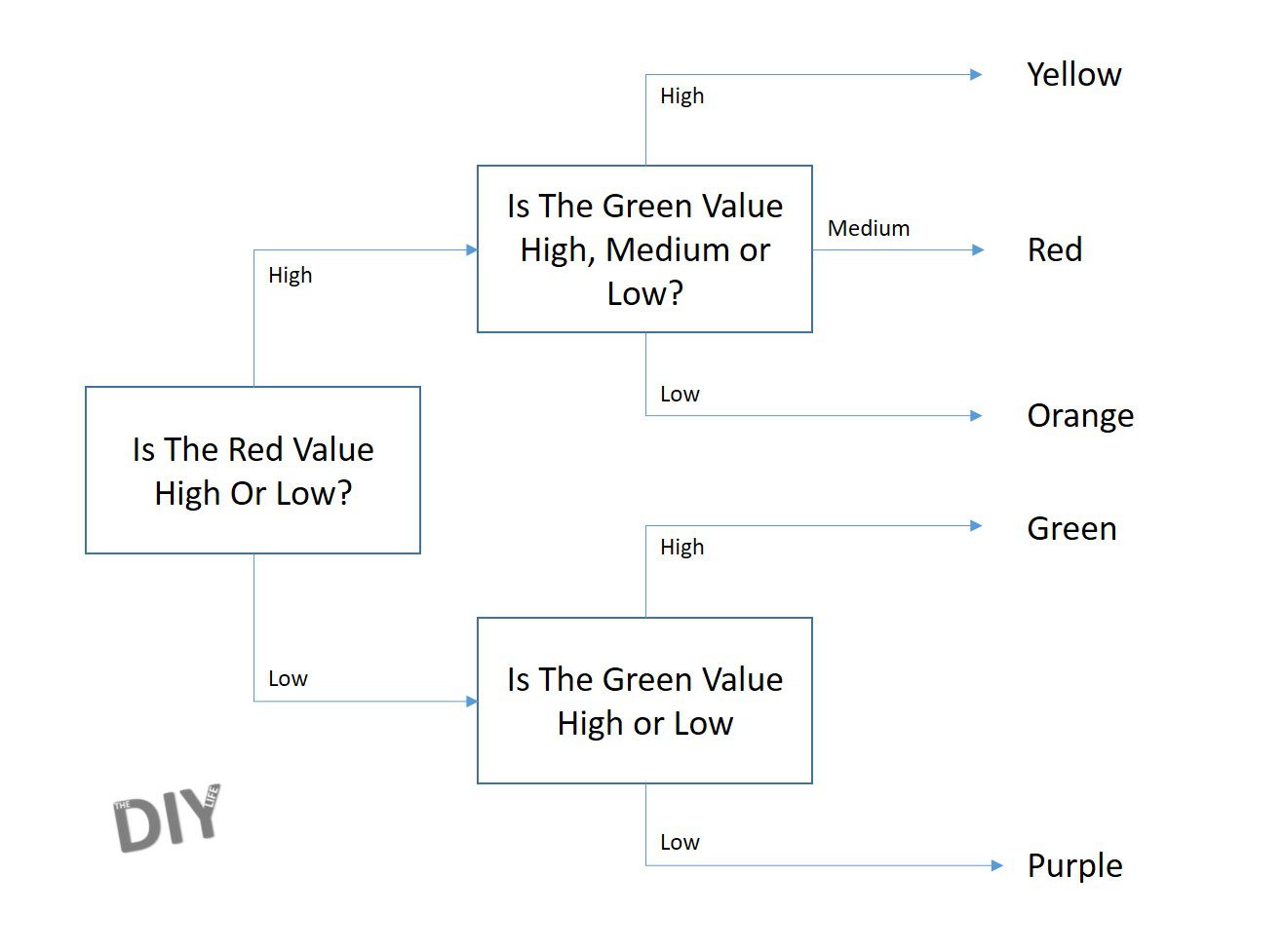
The chooseTube algorithm is structured as a decision tree which is based on the levels of measured colour as follows:
The servo movement functions work on two different principles but are both used to slow down the movement of the servos to make the movement more reliable and stable.
The moveSelector function is based on a position and target reference, either 0, 1 or 2 based on where the selector needs to move next. This is done because the selector moves in a predicable sequence – always from hopper to sensor, sensor to drop and then from drop to hopper again.
The moveSorter function is a bit more complicated because the chute can be in any of the 5 positions and may be required to move to any of the other 4 positions. For this reason there is a global variable sorterPos which keeps track of the sorter’s actual current position and we simply send the function a target position and the function then decides how to move the servo to get to the target position.
It’s just important for troubleshooting or to make adjustments to the code to understand that the one method works on being sent a position reference referring to the array position number 0,1,2 and the other method is sent an actual servo position from 0 to 180.
Setting Up Positions & Calibrating The Colour Set Points
You’ll need to calibrate and set up three things in the code before your sorter will work correctly, we’ll do them in order of increasing complexity.
The first is setting up the sorting positions, or more specifically, the positions of the chute towards each of the tubes. These positions are defined in the array sorterPosition for Yellow, Orange, Red, Green and Purple respectively.
You can test the positions by running the function calibrateSorter in your setup code. This will move the chute to each of the five positions with a two second delay between each movement. You can then make adjustments in the sorterPosition array to get the chute lined up with each tube at each position. This code adjustment will only work if your chute is roughly positioned around the middle tube when it is set to position 90 (the servos midpoint of travel). If not then position your servo at 90 and then reattached the chute so that it’s facing the center tube. You’ll also need to re-upload your code between each adjustment to see the effect it has on the position.
Your next set up is with the selector. You’ll need to do the same as you’ve done above for the chute but now for the selector disk by running the calibrateSelector function.
Check that at position 2, the hole in the selector plate should be aligned with the hopper/funnel hole. At position 1, the hole in the selector plate should be positioned in the middle of the sensor module and at position 0, the hole in the selector plate aligns with the drop hole in the bottom plate. You can test the travel out by placing a Skittle into the hopper and checking that it is picked, moved along to the sensor and then dropped out of the selector after the full travel movement.
Your final calibration is with the colour set points. These are required to ensure that your sorter correctly identifies each colour according to the decision tree. So you need to tell the sorter which values to use to compare the measured colour with. The only way to do this reliably is to test a range of Skittles and see what your sensor measures for each.
I took a sample of 8 of each different colour Skittle, put them into the sorter and displayed the red, green and blue values for each on the Serial monitor, also recording them on a spreadsheet as shown below.
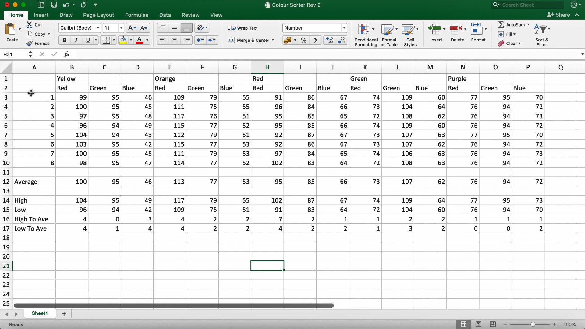
You don’t really need to record the blue values as these were not required in the code. This decision was only made after seeing the values for blue and then adapting the sorting algorithm to suit.
Once you’ve recorded all of your values, you’ll need to look at the recordings and decide on values for the below set points:
colourRedSP – This should be a value which is lower than the lowest red value recorded for the yellow, orange and red Skittles but higher than the highest recorded red value for the green and purple Skittles. This set point allows you to separate the yellow, orange and red Skittles from the green and purple Skittles.
colourGreenSPGP – This should be a value between the lowest green value recorded for the green Skittles and the highest green value recorded for the purple Skittles. This value allows you to separate the green Skittles from the purple Skittles.
colourGreenSPY – This should be lower than the lowest green value recorded for the yellow Skittles and higher than the highest green value recorded for the red Skittles. This value allows you to separate the yellow Skittles from the orange and red Skittles.
colourGreenSPO – This is the final set point and should be lower than the lowest green value recorded for the red Skittles but higher than the highest green value recorded for the orange Skittles. This value allows you to do the final separation of the orange Skittles from the red Skittles.
Once you’ve chosen these values and put them into your code, you’ll be ready to upload the code to your Arduino again and see how your sorter performs.
You may need to make adjustments to your selector and sorter servo positions as you go if Skittles are getting stuck in the hopper or selector or if they’re missing the tubes. You may also need to make adjustments to the set points if you land up with incorrectly sorted Skittles in each tube.
My one initially mixed up Green and Purple skittles quite often as well as Yellow and Orange ones. Playing around with the set points has now resulted in it never getting them wrong, well at least not while sorting a full family sized bag of Skittles.
Skittles do occasionally get stuck in the funnel/hopper, I’ll be trying to design a servo agitator which agitates the Skittles between each sort to ensure that the hopper doesn’t get blocked up.
Have you tried making your own Skittles colour sorter? Let us know in the comments section below or send us your pictures. We’d love to share you designs, tips and tricks.
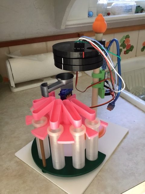
Community Builds
Have a look at this great build by Jeff Trionfante. He added on a 6th tube to sort M&Ms and made some neat additions to the chutes to better guide the M&Ms and Skittles into the correct tubes.
Enjoying making you sorter. Decided to make one for m&ms but the servo for the chute would not travel the full 180° I needed for the extra tube. I decided to substitute a cheapy stepper motor instead. Printing out the modified upper sorter plate now. Will be a nice challenge to code it correctly. Anyway, thanks for the design. Best one I’ve seen so far. Will send a picture when its up and sorting
Thanks for the great feedback Jeff. That sounds awesome, let me know if you run into any trouble with the code, it shouldn’t be too difficult to modify. It would be great to see some pictures when you’re done. Good luck!
Michael,
Decided the stepper route was more complicated then I thought as I would have to reset the starting position at every startup with a switch which my stepper was too weak to engage. I redesigned the upper sorter plate to incorporate the less then 180° travel of the servo, got all the stops recorded and have finished the color calibrations of all the m&ms. The brown ones have the widest ranges. Next step, programming.
Btw, how do I send you a picture on this site? See no place for attachments.
Jeff
Yes, it is quite a bit more complicated in that with a servo you just provide a position reference while with a stepper motor, you need to actually control the movement in order to achieve a specified position. This presents problems with losing power and in particular with this type of project where the movement does not follow a predictable pattern. It just lands up being quite a complicated sketch.
That would be great, you can email some pictures through to admin(at)the-diy-life.com and I’ll get them added.
Hello again, got everything working, but having a problem sorting between red and orange. I will have to play around with the settings. Decided to start with skittles first. My values are a bit different then yours, for instance, the red skittles average are r-163, g-54 and b-51. I used adafruit colorview sketch to get all the readings. Maybe the colors are different in the states owing to whatever food dye regulations there are. Anyway, once I have the skittles down, I’ll tackle the m&ms. Great winter project.
Latest update. Seems I have a faulty sensor. Processing sketch colorview shows no difference between orange and red or yellow and brown. Also showing nearly same values for those colors, which explains why I can’t get them to separate. The sensor did work correctly when I first got it, so I know the wiring is correct. Anyway, I think that is the main problem so I’ve ordered a new one. Let you know when its all working . Bye for now.
Success! Got everything working for the skittles. Didn’t need a new sensor after all (always good to have an extra, though). Changed the gain on line 10 to 60x and the colors were picked up exactly. Tweaked a few variables on lines 16 to 19 and each color went onto its proper tube. Thanks again for all your work on this project. Hope you got my photo.
Today, Skittles. Tomorrow, M&Ms.
That’s great to hear, glad you’ve managed to get it working! I love the additions you’ve made to the chutes. Let us know how you get along with the M&Ms.
Hello, Can we replace the sensor with a arduino camera? Will the same modules be used if we use a arduino camera? My idea is for the camera to take a picture of the subject, then take a histogram of the picture and thus recognize the color of the object.
Hi Sheva,
I’m not sure what type of camera you’re referring to? Arduino’s do not have enough power to do onboard image processing, but you could probably get an external camera to work in this way. Something like a Pixy2 may be able to do what you’re wanting to do.
What is an alternative then to print the 3D design? I can’t afford to buy a $300+ printer. I’m in beginning stage on work on the color sector. What part was most difficult for you?
You could make the components out of wood, mdf or cardboard as well. I’ve seen some pretty cool designs made almost entirely out of cardboard. Getting the system calibrated and identifying the different colours reliably was one of the most difficult parts.
Hello,
great project. Do you have the CAD files by any chance?
Thanks
i have no idea how the code works how can i make it so in the beginning the servo with the motor sets itself to position 0?
i have no idea how the code works how can i make it so in the beginning the servo with the motor sets itself to position 0?
The hopper isn’t in the print files. Do you happen to have it/can you update the zip file to include it?
I have everything set up and the top servo is working fine but cant get the selector servo to work all? Have I miss something?