This is a really easy RFID door lock mechanism which is based on the Arduino Uno and the RC522 RFID sensor, which allows you to use RFID tags or cards to lock and unlock a door, drawer or cupboard. You can load as many RFID tags as you’d like onto the Arduino and add or remove tags to provide more or fewer people with access. The lock is actuated with a micro servo, which can be used along with the 3D printed lock provided in this example, or any standard bolt type lock available from your local hardware store.
This guide assumes that you’ve worked with an Arduino micro-controller before and know the basics of programming an Arduino. If you do not, follow the linked guide for more information on creating and uploading your first sketch.
Here is a summary of the build, continue reading for full step by step instructions along with the code and print files:
What You Need To Make Your Own Arduino Based RFID Lock
- Arduino Uno (Or Other) – Buy Here
- Arduino Power Supply – Buy Here
- RC522 RFID Sensor – Buy Here
- Breadboard & Jumpers for Testing – Buy Here
- Micro Servo – Buy Here
- 2 x LEDs – Buy Here
- 2 x 220Ω Resistors – Buy Here
- 3D Printer & Filament (Optional for Lock) – This One Used
How To Make Your RFID Door Lock
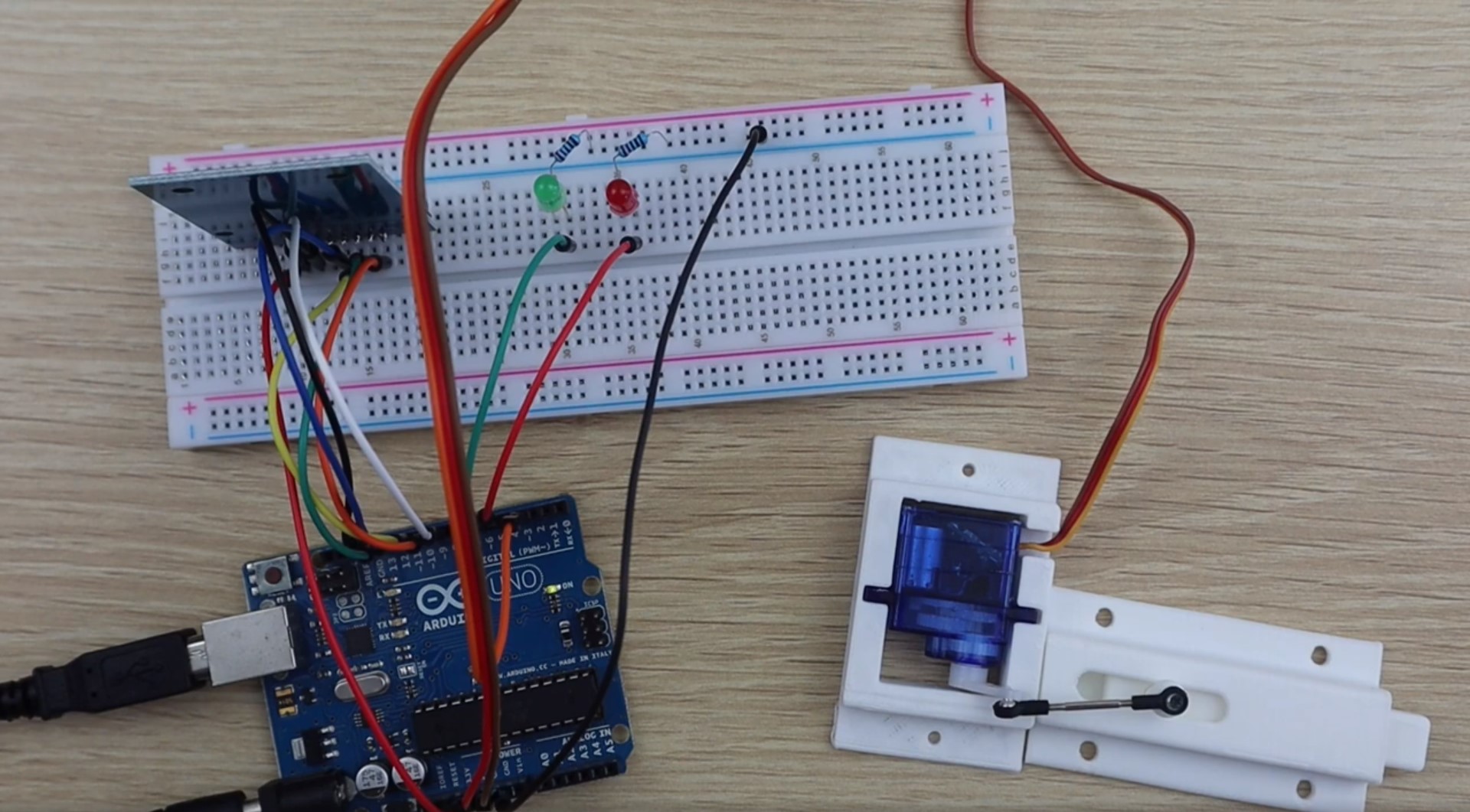
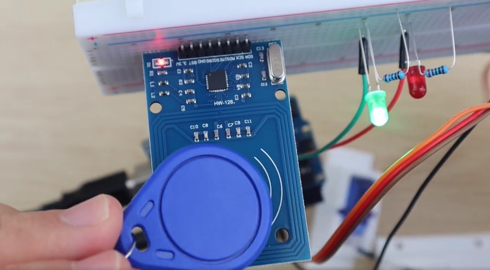
To start off, lets connect the RFID sensor, LEDs and servo to your Arduino using a breadboard. This will enable you to test the circuits and to read the serial numbers from your tags in order to load them into the array in your code so that they open the lock.
The Circuit
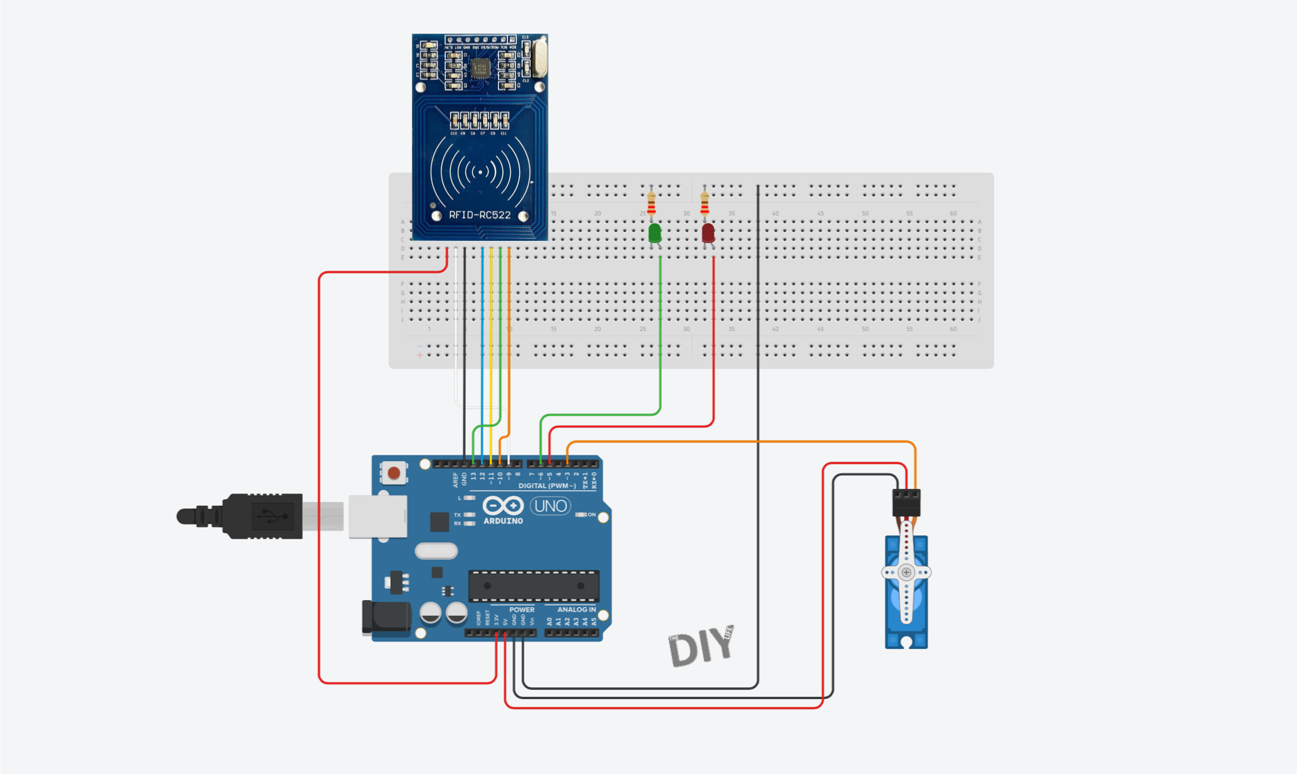
The RC522 sensor is going to be connected to our Arduino using the SPI interface. We are then going to connect a green LED which will flash to show that a tag has been read and access has been granted and a red LED which will flash to indicate that a tag has been read an access has not been granted. Lastly, a micro servo will be used to open and close the locking mechanism. The LEDs and micro servo are connected using typical Arduino circuits.
Here is the circuit:
Once you’ve got the circuit connected on your breadboard, you’ll need to print and assemble your lock mechanism.
Building The Lock Mechanism
If you’ve got a 3D printer, the easiest way to get started with an RFID door lock is to print out the below components and servo bracket. The lock mechanism is based on this sliding lock design by Sagittario which I have scaled down to 65% of the original size.
I 3D printed the lock mechanism and servo holder using white PLC at 185C and 20% infill.
Download 3D Print Files: RFID Lock 3D Print Files
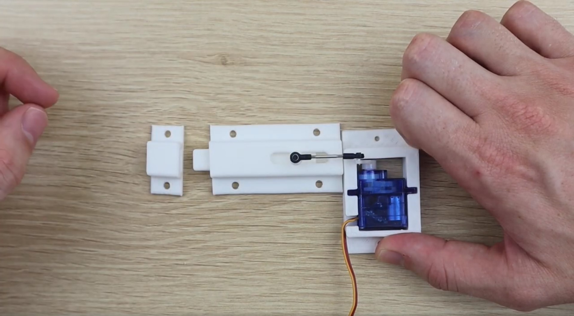
If you don’t have a 3D printer, you can use any standard bolt type sliding lock available from your local hardware store. You’ll just need to attach one end of the servo push rod to the bolt to actuate it. You’ll also need to build a simple servo bracket to hold the servo in place behind the lock. You can just epoxy or glue the servo in place, but a screwed on bracket is usually a bit stronger.
Uploading The Code
Once you’ve assembled your lock mechanism, you’re ready to upload your code and load your tag numbers into the array.
Here is the code:
//The DIY Life
//Michael Klements
//27 January 2020

#include <SPI.h>
#include <RFID.h>
#include <Servo.h>

RFID rfid(10, 9);       //D10:pin of tag reader SDA. D9:pin of tag reader RST
unsigned char status;
unsigned char str[MAX_LEN]; //MAX_LEN is 16: size of the array

String accessGranted [2] = {"310988016", "19612012715"};  //RFID serial numbers to grant access to
int accessGrantedSize = 2;                                //The number of serial numbers

Servo lockServo;                //Servo for locking mechanism
int lockPos = 15;               //Locked position limit
int unlockPos = 75;             //Unlocked position limit
boolean locked = true;

int redLEDPin = 5;
int greenLEDPin = 6;

void setup()
{
  Serial.begin(9600);     //Serial monitor is only required to get tag ID numbers and for troubleshooting
  SPI.begin();            //Start SPI communication with reader
  rfid.init();            //initialization
  pinMode(redLEDPin, OUTPUT);     //LED startup sequence
  pinMode(greenLEDPin, OUTPUT);
  digitalWrite(redLEDPin, HIGH);
  delay(200);
  digitalWrite(greenLEDPin, HIGH);
  delay(200);
  digitalWrite(redLEDPin, LOW);
  delay(200);
  digitalWrite(greenLEDPin, LOW);
  lockServo.attach(3);
  lockServo.write(lockPos);         //Move servo into locked position
  Serial.println("Place card/tag near reader...");
}

void loop()
{
  if (rfid.findCard(PICC_REQIDL, str) == MI_OK)   //Wait for a tag to be placed near the reader
  {
    Serial.println("Card found");
    String temp = "";                             //Temporary variable to store the read RFID number
    if (rfid.anticoll(str) == MI_OK)              //Anti-collision detection, read tag serial number
    {
      Serial.print("The card's ID number is : ");
      for (int i = 0; i < 4; i++)                 //Record and display the tag serial number
      {
        temp = temp + (0x0F & (str[i] >> 4));
        temp = temp + (0x0F & str[i]);
      }
      Serial.println (temp);
      checkAccess (temp);     //Check if the identified tag is an allowed to open tag
    }
    rfid.selectTag(str); //Lock card to prevent a redundant read, removing the line will make the sketch read cards continually
  }
  rfid.halt();
}

void checkAccess (String temp)    //Function to check if an identified tag is registered to allow access
{
  boolean granted = false;
  for (int i=0; i <= (accessGrantedSize-1); i++)    //Runs through all tag ID numbers registered in the array
  {
    if(accessGranted[i] == temp)            //If a tag is found then open/close the lock
    {
      Serial.println ("Access Granted");
      granted = true;
      if (locked == true)         //If the lock is closed then open it
      {
          lockServo.write(unlockPos);
          locked = false;
      }
      else if (locked == false)   //If the lock is open then close it
      {
          lockServo.write(lockPos);
          locked = true;
      }
      digitalWrite(greenLEDPin, HIGH);    //Green LED sequence
      delay(200);
      digitalWrite(greenLEDPin, LOW);
      delay(200);
      digitalWrite(greenLEDPin, HIGH);
      delay(200);
      digitalWrite(greenLEDPin, LOW);
      delay(200);
    }
  }
  if (granted == false)     //If the tag is not found
  {
    Serial.println ("Access Denied");
    digitalWrite(redLEDPin, HIGH);      //Red LED sequence
    delay(200);
    digitalWrite(redLEDPin, LOW);
    delay(200);
    digitalWrite(redLEDPin, HIGH);
    delay(200);
    digitalWrite(redLEDPin, LOW);
    delay(200);
  }
}
Download the code: RFID Sensor Sketch
Before you upload your code, you’ll need to install the RFID library which is bundled with the sketch zip file. This is easily done in your Arduino IDE by clicking on Sketch -> Include Library -> Add .ZIP Library and the selecting the zipped library file.
In the code we first include the required libraries and then set up the sensor object and an array to return the read tag serial number.
The next array and its associated size is used to store the serial numbers for all of the tags which you’d like to grant access to. You’ll need to find and update these numbers using the serial monitor by uploading this code and then scanning your tags. The Serial monitor will display the tag’s serial number and then state that access is denied. Copy this number into the array accessGranted, update the array size (number of tags registered) and then re-upload the code. You could also write a short section to enable you to register a new tag by pushing a button inside the sensor component box or inside the door for example.
We then set up the servo object and it’s travel limits. You may need to make adjustments to these limits to get your servo to move through it’s full range without over-travelling in either direction.
In the setup code, we connect to the RFID sensor, define the LED pins and then run through a quick LED flash startup sequence before making sure that the lock is in the locked position. You can remove the Serial monitor output lines in the code in your final version, these are just useful for registering your tags and debugging the system when you first assemble it.
We then run through the loop which waits for a card or tag to be scanned, determines its serial number and then passes this serial number through to a function called checkAccess to verify whether the tag number can grant access or not.
The checkAccess function simply takes the read tag number and then cycles through the array of accepted numbers to see if it is an accepted tag. If a match is found then the green LED is flashed and the lock is either opened or closed, depending on the previous state. If the tag number is not found in the array then the red LED is flashed and the lock is not opened.
Adding or Removing Accepted Tags
As mentioned in the previous step, the array accessGranted is used to store the serial numbers of the accepted tags and the integer accessGrantedSize stores the number of entries in this array.
To add a tag, you’ll need to scan the tag with the Serial monitor open on your PC. You’ll then get a message saying that the card has been read along with the serial number of the card and a message saying “Access Denied”. Simply copy this number into the array and update the size integer to reflect the new number of tags. Re-upload the code and you should now get an “Access Granted” message on the Serial monitor.
To remove a tag, find the tag serial number in the array (you may need to scan it as done previously) and remove it from the array. Update the array size for any tags which you remove as well.
It is fairly easy to include a push-button or two on the inside of the door or in the component box which will allow you to add or remove tags without having to update the code.
Using the Lock
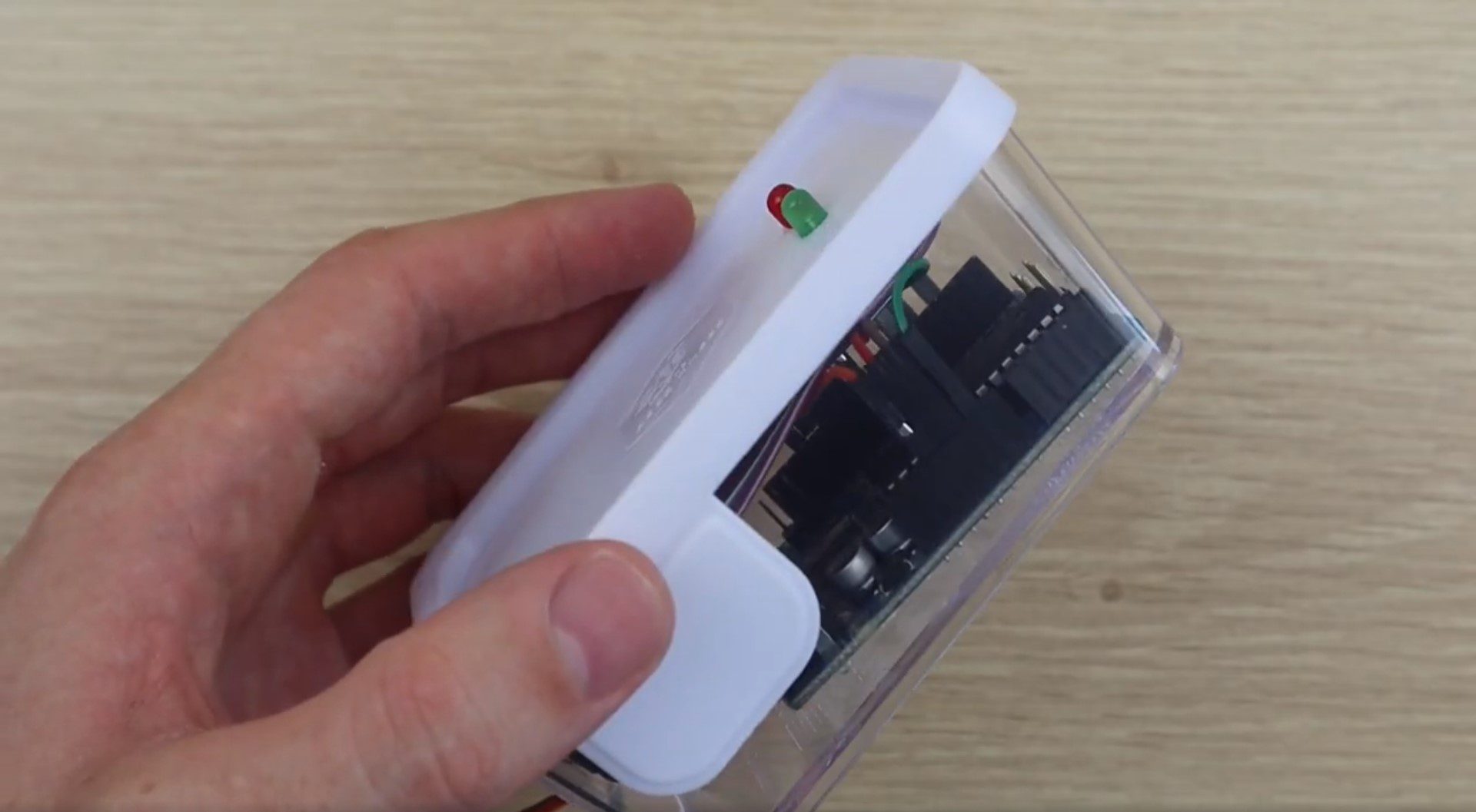
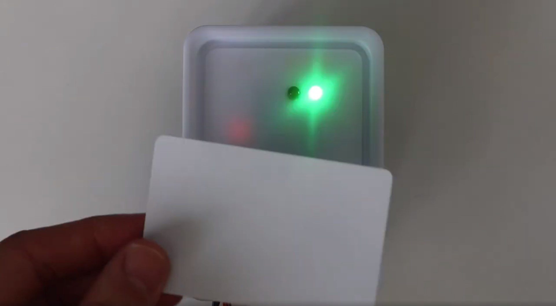
You should now have a functioning RFID locking mechanism which can be easily installed onto a door, cupboard or container to restrict access to it. You can also put the sensor components into a simple container or housing to mount on the front side of the door, like this:
There are a couple of ways to make this lock a bit more secure if you’re actually going to be using it to secure a room or cupboard.
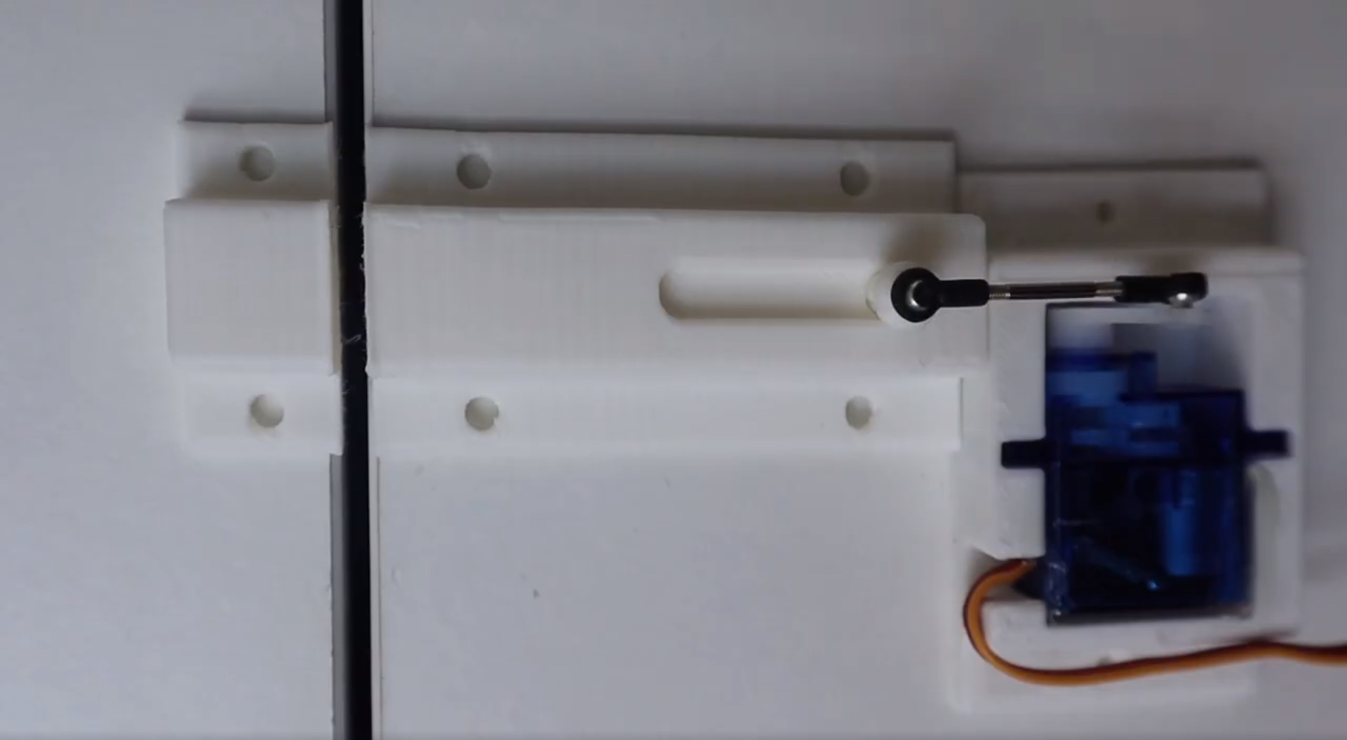
Start by replacing the 3D printed lock with a proper metal lock from a hardware store. Make sure that you have a solid connection between the lock and the servo and try to position the servo such that the arm is in line with the push-rod and the head of the slider when it is in the locked position. This will ensure that you can’t slip a thin object through the gap in the door and try to push the slider open, you’ll be pushing against the centre of the servo and not relying on the torque provided by the servo to keep the slider in place.
Next, place as few of the electronic components outside as possible. It is better to have the actual Arduino and servo connection inside the room or box and place only the RFID sensor and LEDs outside. It’s much more difficult to trick the Arduino into opening the lock using the RFID sensor connection than it is to simply provide a PWM signal to the servo to unlock the door.
Have you built your own RFID door lock using an Arduino? Is there anything you’d suggest doing differently?Let us know in the comments section below.
mine just has a red light but dosnt read or anything when i try to scan
Same here. I do not know how to fix it
Ua mine dose the same
mine says the .zip library doesn’t contains a valid library
He packaged it very badly lol. You have to keep clicking on the folders inside of each other until you get to the folder right before the examples and stuff.
There are only two folders in the package, one called RFID which contains the sketch and another called RFID Library which contains the zipped library file. This .zip library is a standard format for a library and should just be imported into the IDE, not unzipped as well.
mine says
RFID.h: no such file or directory
what should i do
Install the RFID.h library which is included in the download
du kleiner Wi**ser
p
how do i install the library file its not working for me
Drop the zip file into your libraries folder or import library from zip in your IDE
Hello you help me what’s app +989189230140 chat yes help soory
How to fix with “A library named RFID already exists.” Thank you!
Open your libraries folder and delete the old RFID library then re-install the new one.
I am having trouble registering my tags. When i click on serial monitor, my two lights turn on and off but nothing happens when i scan my tags.
Hi Ty,
It’s likely a communication issue between the reader and your Arduino. Are you using the tags that came with the reader?
Whatesapp
I am having the same problem as Ty I have built the circuit correctly and the LEDs light up the RFID reader just isn’t reading the cards I don’ know if it that i am using the blue version of the RC-522 or not.
same here!
i am using the blue reader and mine works perfectly fine, maybe try checking the code to see if there are any issues there
i am using the blue reader and mine works perfectly fine, maybe try checking the code to see if there are any issues there
How do you drop the zip file
? I have been trying to get this working but it just isn’t
the lib is not working for me its saying RFID.h such directory is not found
You need to install the RFID library that is bundled with the download.
hey there, I uploaded the code and so far it was good but when I opened the serial monitor it would not scan the card or tag which came with the reader. every time i upload the code a light on the RFID sensor blinked. the led’s wont light up either, how would i go about to fix this?
I had the same problem, if your RC 522 is blue you need to convert the pins so it can read the card.
Could you share some more information on this? The RC 522 I’ve used here is blue and didn’t need any pin conversions?
hi am padi
cant find most of the things needed for the project on the proteus so cant draw them how do i go about it
Hi there, I have followed all the instructions you have posted yet I have had no success. I have wired all the components properly by following your schematic and have used your RFID library. When I uploaded the code the LED’s lit up but when I went to scan the cards which came with the reader nothing was displayed on the serial monitor. I even went as far as buying new components because I was under the impression that the parts I had received were faulty. Please help as it would be much appreciated. 🙂
Hi there, I have followed all the instructions you have posted yet I have had no success. I have wired all the components properly by following your schematic and have used your RFID library. When I uploaded the code the LED’s lit up but when I went to scan the cards which came with the reader nothing was displayed on the serial monitor. I even went as far as buying new components because I was under the impression that the parts I had received were faulty. Please help as it would be much appreciated. 🙂
i TO
hi i have an error :Arduino : 1.8.13 (Windows 10), Carte : “Arduino Mega or Mega 2560, ATmega2560 (Mega 2560)”
RFID:6:10: fatal error: RFID.h: No such file or directory
#include
^~~~~~~~
compilation terminated.
exit status 1
RFID.h: No such file or directory
Ce rapport pourrait être plus détaillé avec
l’option “Afficher les résultats détaillés de la compilation”
activée dans Fichier -> Préférences.
please help
you have to download the library
Sorry I meant to say red here are the conversions if your RC-522 is red
VCC – 3.3v
RST – 9~
GND – GND
MIOS – 12
MOSI – 11
SCK – 13
NSS – 10
RQ – goes no where
This should work if you have problems with the RC – 522 reading a card or if it is a different colour to what was used in the video
Hope this is helpful
Will
Thanks for providing this information!
Michael, this may be a crazy question. Do the power source have to be plugged into the board in order to use? Meaning, how long does it operate without being plugged into a power source
Yes ofc the power source has to be plugged into the board, how else would anything plugged into the arduino operate? if there is no power source it would just be off.
I am not Michael but I can still answer your question
The board has to be plugged into a power source such as a PC or a battery to work. So trying to use it unplugged wont get you very far
I swipe the card and it just doesn’t do anything. I tried to understand this from the card but I really didn’t.
There are no errors in the code.
Help please!
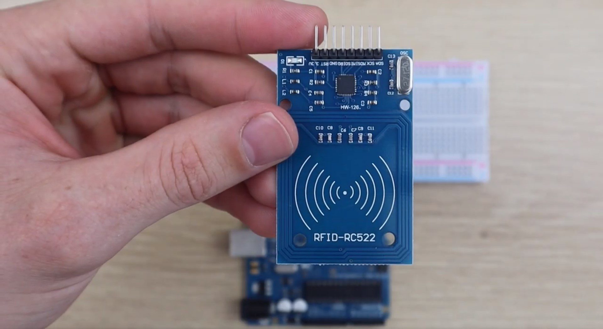
the sensor should be placed vertically as shown in the picture. i know it sounds stupid but trust me it works. place the sensor vertically and it will read your cards then.
As I said earlier in the comments if your RC – 522 is red then you have to change the pin order accordingly to this:
VCC – 3.3v
RST – 9~
GND – GND
MIOS – 12
MOSI – 11
SCK – 13
NSS – 10
RQ – goes no where
The pins on the right side are the RC – 522 for reference.
hi, what if your RC is blue?
How can i do this in bluetooth?
If I could open the lock using your cell phone…
You would need a Bluetooth module and then you’d then need to code a mobile phone app that allowed you to activate the lock based on a button or something similar.
compilation terminated.
exit status 1
Error compiling.
whats the problem?
does anyone have a solidwork file for lock?
Hello, I love this idea but I don’t have an Arduino Uno. Can I use the Mega 2560?
Error:
Four_Digital:615:1: error: a function-definition is not allowed here before ‘{‘ token
{
^
Four_Digital:634:1: error: a function-definition is not allowed here before ‘{‘ token
{
^
Four_Digital:656:1: error: a function-definition is not allowed here before ‘{‘ token
{
^
Hi, I succeeded in this project and I enjoyed it very much. Though when I unplug the upload cable it doesn’t activate the servo motor, even though I attached a 9v battery. Help?
When I try to upload the library, my IDE keeps showing an error message saying “The specified fill does not contain a valid library”. How do I fix it?
pg slot, which game is good the current new game, the best PG SLOT in 2023 New website currently open That is very popular in the form of online slots games, PG slots online, the best
The best slot games from PG are engaging in many beneficial activities for all gamers. Which the main reasons why we have to join this camp are: PG SLOT
Hi Everyone – I was having the same issues as lots of folks here, and I got it working using the article here: https://lastminuteengineers.com/how-rfid-works-rc522-arduino-tutorial/
Turns out the issue is that I was using an Arduno Mega2650, so the SPI pins are different. I moved my wires around according to that article’s mapping for the mega, and it still didn’t work! Then I noticed the line in the code RFID(10,9). The 10 pin there was part of my remapping, so I updated the code to match my new SDA pin location.
Anyways, hope this helps, I now have my codes for the sensor!
Could you please explain what you did?
thank you for this useful informations. we are เล่นสล็อต mega the best slot game. please visit my webside please
how to install the rfid library i download the file but I did not find anything
I am just starting out with Arduino boards and programming and this project was exactly the type that got me attracted to this new hobby in the first place.
I successfully repeated all the instructions provided using the recommended hardware (RFID-RC522 ‘blue’ and Arduino Uno R3). Reading through some of the other comments and questions, I encountered a similar initial problem with installing the RFID library – but this was resolved by making sure to Upload the RFID.zip file that is LOCATED WITHIN the RFID Library folder – rather than the trying to upload the downloaded all-inclusive RFID.zip file (which contains the RFID Library folder).
A second initial problem was that I mistakenly had the RFID-RC522 installed in reverse direction within the breadboard – a quick check of the header pin labels showed the correct way. All works perfectly.
Cheers,
What do you mean by “within the RFID Library Folder”. I click on the file and it doesn’t allow me to go inside it. Just says the same thing over and over which is “error in opening zip file”. What am I doing wrong? Please someone help me with uploading the library.
hi, what if your RC is blue?
Hello everyone, I was facing similar issues to many of you. To fix the RFID reader not scanning anything/nothing showing up on the serial monitor put the RFID-RC522 the other way around. In the schematic it placed the wrong way.
Hello my friend,
I’m following your works and it’s amazing.
I’m looking for to have RFID access the same here but with wider range (about 1 to 2 meters), can we have the same with that distance.
appreciated your support.
This RFID door lock project sounds super cool! I love how easy it seems to set up with the Arduino Uno and RC522 sensor. It’s great that you can customize access by adding or removing tags. I’m imagining all the practical uses, like keeping my secret stash of snacks in a locked drawer. Have you tried using different types of RFID tags? I wonder if some work better than others. And how do you think this could be adapted for a larger, more commercial door?
Thank you very much! It is very interesting!