Have you ever wanted to take crisp photos of lightning during a storm without having to rely on chance or leaving the camera on a really long exposure. You have just under 200 milliseconds to see the lightning, push the camera’s shutter release and allow the camera time to take the photo which is next to impossible to get right once, never mind for a range of photos. You need an automatic camera trigger to get the shot.
The Arduino lightning trigger is the answer, it will detect the lightning strike and trigger your camera for your to ensure that you get the right timing and a clear photograph. All you need is an SLR camera which is able to be remotely triggered, an Arduino controller and a couple of cheap components.
You can also use this device to trigger your camera from far away using a laser pointer.
This project assumes you know the basics of Arduino programming, otherwise read our article on getting started with Arduino.
What You Will Need For An Arduino Lightning Camera Trigger
- An Arduino (Uno used here) – Buy Here
- An LDR (Light Dependent Resistor) – Buy Here
- A 10K Resistor – Buy Here
- A 220Ω Resistor – Buy Here
- An Optocoupler (4N35 Used Here) – Buy Here
- Lower Resistance Option (PC817) – Buy Here
- Camera Trigger Connection Lead – Buy Here Canon, Nikon & Sony
How To Build A Lightning Camera Trigger
The LDR is the sensor in this project, the light from the lightning changes the resistance of the LDR which the Arduino detects as a change in voltage and the Arduino then triggers the camera through the optocoupler. The optocoupler is not entirely necessary and you can get around using one by assigning the pins on the Arduino differently however, for the few cents it costs, it offers isolation and protection for the camera which can cost a few hundred or thousand to repair if the Arduino puts the wrong signal or voltage onto the cameras trigger terminals and damages the cameras circuitry.
Assemble The Components
First you need to assemble your components, if you are making a temporary trigger then a breadboard is perfect. Assemble the components as shown in the circuit diagram below.

Note that the LED and battery in the below breadboard model are merely used in this example to illustrate that the optocoupler has been triggered, in reality these shouldn’t be connected as you don’t want a voltage to be applied to the camera trigger.
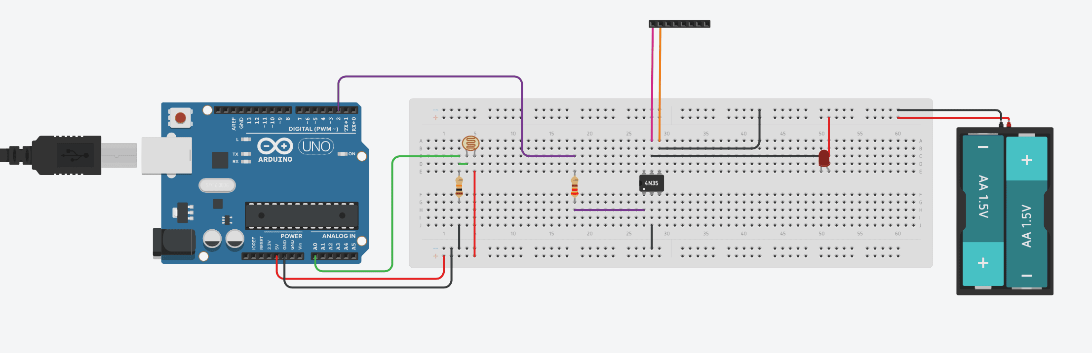
Connect your camera trigger cable’s ground to the purple wire going to the black header and the cable’s shutter release to the orange wire on the header.
Note that the optocoupler is only used to trigger the shutter release pin on your camera, your camera’s trigger cable may have three wires, the third is to remotely trigger the focus. Triggering the focus has been omitted in this project as it generally takes too long for the camera to focus and trigger in the time that the lightning is visible. The camera should therefore be used in manual focus mode. If your camera insists on the focus pin being used to release the shutter then connect it to the ground pin and this keeps the camera focus locked.
Some people have reported that the 4N35 is not able to trigger their SLR due to its high internal resistance. I have therefore added a lower resistance option to the parts list, the PC817. You can also use a EL 817-c.
Upload the Sketch
Now you can upload your sketch onto your Arduino, if you haven’t uploaded a sketch before then follow this guide on getting started.
//The DIY Life
//Michael Klements
//13 December 2016

int shutterPin = 2;  //Assign the LDR and optocoupler pins
int triggerPin = 0;
int triggered =0;

void setup()
{
  pinMode(shutterPin,OUTPUT);    //Define the shutter pin as an output
  digitalWrite(shutterPin,LOW);  //Set the shutter pin to low / off / no voltage
}

void loop()
{
  triggered = map(analogRead(triggerPin), 0, 1023, 0, 1023);  //Read the output from the LDR
  if (triggered >= 100)  //If light is detected, trigger the camera
  {
    delay(50);    //Wait for lightning to be the brightest
    digitalWrite(shutterPin,HIGH);  //Trigger camera
    delay(1000);
    digitalWrite(shutterPin,LOW);   //Reset camera trigger output for next photo
    triggered = 0;
  }
}
Here is the link to download the Lightning code.
The code first assigns the shutter release to pin 2 and sets the output to Low or Off.
Next the Arduino takes constant readings from the LDR until the reading exceeds the set point in Row 18 (100 in this case). The controller then activates the optocoupler which triggers the camera.
Calibrate the Set Point & Timing
There are two settings which need to be adjusted to suit your light conditions and your camera’s timing.
The first is the trigger sensitivity, the number in line 18 which is tested by the if statement. In this case, it is set to trigger on any value over 100 which is suitable for quite dark surroundings and will trigger with a small amount of light. If the sensitivity is too high, the camera will be set off all the time, adjust this parameter upwards with a higher number. If the sensitivity is too low and the camera is missing lightning strikes then adjust this parameter downwards with a lower number. This parameter will probably have to be changed every time you use the trigger as it is dependent on the current conditions.
The second parameter to adjust is the timing in line 20. This depends on two things, one is how bright and developed you want the lightning to appear in the photograph and the second is how fast your camera responds to the trigger command. More modern cameras react faster and therefore longer delays are needed to allow the lightning to fully develop before triggering the camera. Adjust the delay to be shorter if the camera is missing the lightning and longer if the camera is taking the photo before the lightning is fully developed.
Potentiometer Set-Point Modification
I’ve included this modification as an adaptation to the original circuit as a number of people have asked me how they can make the trigger set-point adjustable in the field instead of having to take their computer along with them.
This can easily be done by adding a 10K potentiometer circuit onto one of your Arduino’s analogue inputs and changing a few lines in the code.
Add a 10K potentiometer onto your Arduino analogue input A1 as shown in the diagram below:
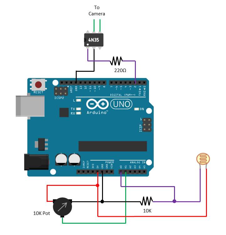
Now you’ll need to modify your Arduino code to accept the potentiometer input as your new trigger set-point.
To do this you’ll need to add two new variables, one for the triggerPointPin and one for the actual set-point measured from the pot – triggerPoint. Then you’ll need to read in the potentiometer value in the setup loop and save the value to the triggerPoint variable. Lastly you’ll change the set-point comparison line to be compared to the triggerPoint variable instead of the preset value.
//The DIY Life
//Michael Klements
//13 December 2016

int shutterPin = 2;  //Assign the LDR and optocoupler pins
int triggerPin = 0;
int triggerPointPin = 1;
int triggered =0;
int triggerPoint = 0;

void setup()
{
  pinMode(shutterPin,OUTPUT);    //Define the shutter pin as an output
  digitalWrite(shutterPin,LOW);  //Set the shutter pin to low / off / no voltage
  triggerPoint = map(analogRead(triggerPointPin), 0, 1023, 0, 1023); //Read the output from the potentiometer
}

void loop()
{
  triggered = map(analogRead(triggerPin), 0, 1023, 0, 1023);  //Read the output from the LDR
  if (triggered >= triggerPoint)  //If light is detected, trigger the camera
  {
    delay(50);    //Wait for lightning to be the brightest
    digitalWrite(shutterPin,HIGH);  //Trigger camera
    delay(1000);
    digitalWrite(shutterPin,LOW);   //Reset camera trigger output for next photo
    triggered = 0;
  }
}
Here is the link to download the Modified Lightning code.
I’ve added the potentiometer reading to occur in the setup loop of the code so that you’re not wasting processing time in the main section of the code to keep your Arduino’s reaction time as fast as possible. This does have one disadvantage in that you’ll need to reset your Arduino each time you make adjustments to the pot in order to “take” the new setting. This will take a second or so, so it shouldn’t be much of an issue. If you have a fast camera then you may be able to include it in the main section of the code as well without compromising the performance of the circuit.
Community Builds
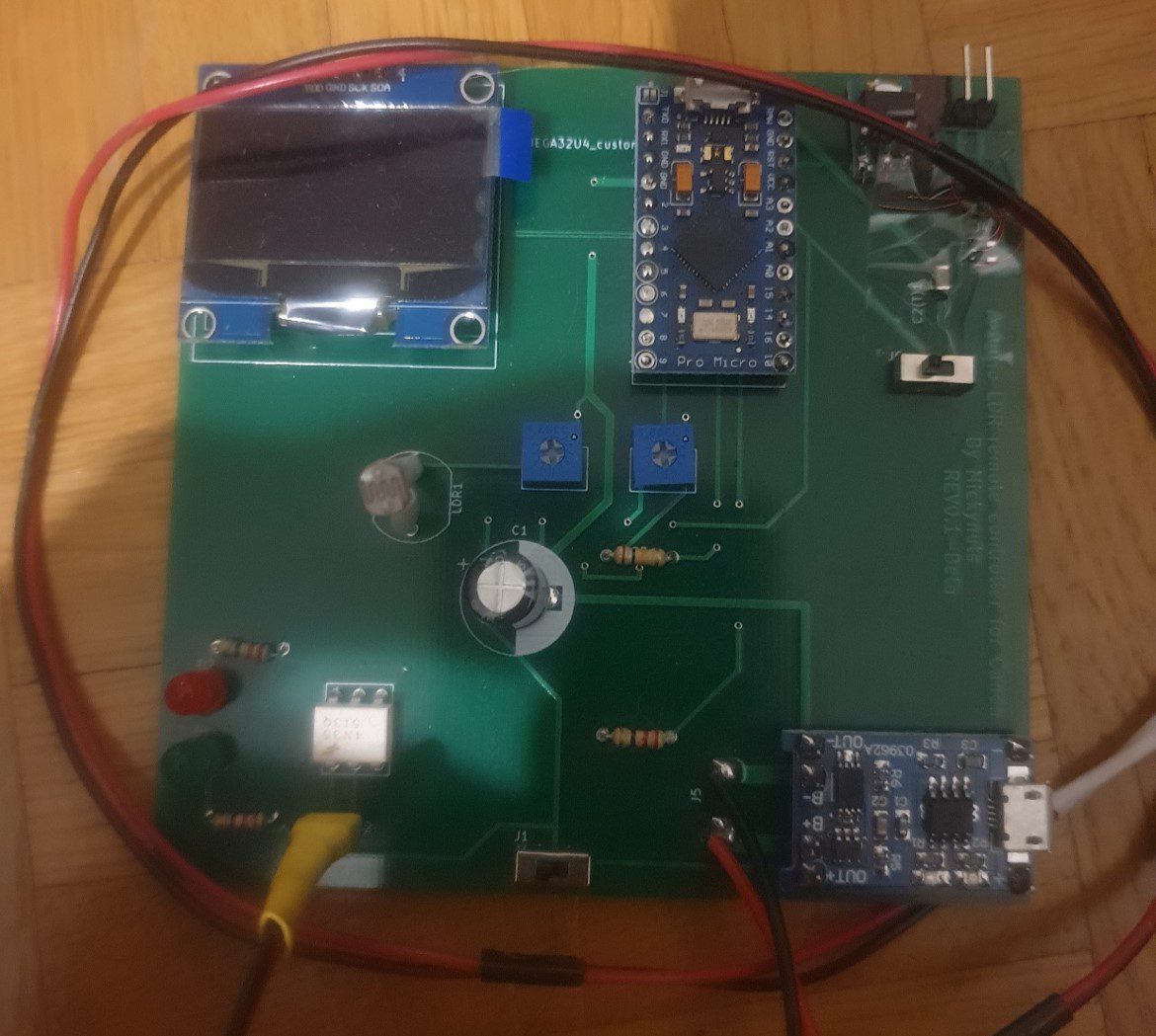
Michael Aramini has built upon the design and turned the camera trigger into a PCB which is driven by an Arduino Pro Micro and has setpoint adjustments for the light trigger level and the delay time using two pots. These setpoints, as well as the current light level, are displayed on an OLED display.
Here is the PCB:
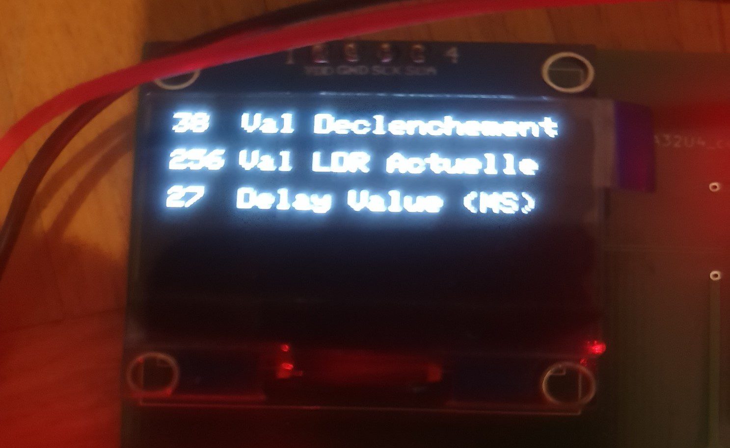
When in use, the OLED display shows the current light level as measured, the lightning light level setpoint, and the delay setpoint.
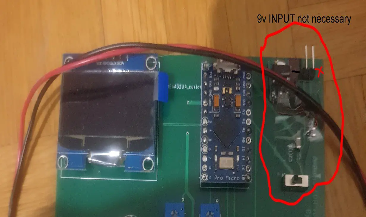
The board is powered using an old mobile phone battery and has a USB charger module designed onto the PCB to charge the phone battery.
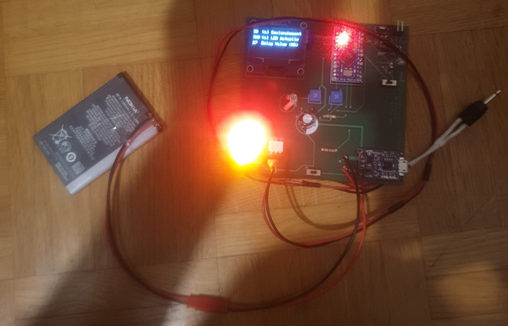
There is also a circuit on the top to power the board using an external 9V battery.
What You’ll Need To Build Your Own
To build your own lightning trigger PCB, you’ll need:
- Arduino Pro Micro 5V – Buy Here
- 3.7V Lithium Ion Battery (From Old Mobile Phone)
- I2C OLED Display – Buy Here
- 220uf 10v Capacitor – Buy Here
- 2 x 5mm LEDs – Buy Here
- 3 x 220Ω Resistors – Buy Here
- 10K Resistor – Buy Here
- LDR – Buy Here
- 4N35 Optocoupler – Buy Here
- TP4056 Charge Controller – Buy Here
- 2 x 10K Trim Pot – Buy Here
- 2 x Micro Slide Power Switch – Buy Here
To Build The 9V Battery Power Circuit:
- 22uf Tantal or céramic SMD
- 10uf Tantal or céramic SMD
- AMS1117 5v
The Code
I have modified the code slightly to include comments, make it a bit easier to follow, and translated his French display text to English, the general functionality is still identical:
int ledSignal = 14;                               //Assign the LED pin
int shutterPin = 15;                              //Assign the optocoupler pin number
int triggerPin = 0;                               //Assign the LDR analog pin number
int triggerPointPin = 1;                          //Assign the trigger setpoint analog pin number
int delayValPin =2;                               //Assign the delay setpoint analog pin number
int triggered =0;                                 //Variable to store the LDR reading
int triggerPoint = 0;                             //Variable to store the trigger setpoint
int delayVal = 0;                                 //Variable to store the delay setpoint


#include <SPI.h>                                  //Include the libraries to control the OLED display
#include <Wire.h>
#include <Adafruit_GFX.h>
#include <Adafruit_SSD1306.h>
#define OLED_RESET 4
Adafruit_SSD1306 display(OLED_RESET);             //Create the display object

void setup()
{
  Serial.begin(9600);                             //Start serial communication (only required for debugging)
  display.begin(SSD1306_SWITCHCAPVCC, 0x3C);      //Connect to the display
  display.clearDisplay();                         //Clear the display
  display.setTextColor(WHITE);                    //Set the text colour to white
  pinMode(shutterPin,OUTPUT);                     //Define the shutter release pin mode
  pinMode(ledSignal,OUTPUT);                      //Define the LED pin mode
  digitalWrite(shutterPin,LOW);                   //Set the shutter pin to low / off
}

void loop()
{
  triggerPoint = analogRead(triggerPointPin);     //Read in the trigger setpoint
  triggered = analogRead(triggerPin);             //Read in the current LDR level
  delayVal = analogRead(delayValPin);             //Read in the delay setpoint
  display.clearDisplay();                         //Display the read in values on the OLED display
  display.setCursor(0,0);
  display.print(triggerPoint);
  display.setCursor(23,0);
  display.println("Trigger Setpoint");
  display.setCursor(0,15);
  display.print(triggered);
  display.setCursor(23,15);
  display.println("LDR Reading");
  display.setCursor(0,30);
  display.print(delayVal);
  display.setCursor(23,30);
  display.println("Delay (ms)");
  display.display();
  Serial.println("A1-Trigger Setpoint");          //Display the read in values on the serial monitor
  Serial.println(triggerPoint);                           //Can be removed after debugging
  Serial.println("A0-LDR Reading");
  Serial.println(triggered);
  Serial.println("A2-Delay (ms)");
  Serial.println(delayVal);
  if (triggered >= triggerPoint)                  //If measured light is higher than the setpoint
  {
    delay(delayVal);                              //Wait the delay time for lightning to be the brightest
    digitalWrite(shutterPin,HIGH);                //Trigger camera
    digitalWrite(ledSignal,HIGH);                 //Light up the LED
    delay(1000);                                  //Wait one second, avoids retriggering if lighting is still bright
    digitalWrite(shutterPin,LOW);                 //Release the trigger
    digitalWrite(ledSignal,LOW);                  //Turn off the LED
  }
}
Download The Sketch – PCBTriggerSketch
Here are the PCB files if you’d like to get your own PCB made. Remember that this is a first revision of the PCB, so you should check the circuit and suitability with your own components before ordering your own – Download the PCB Files.
Well done on a great build!
Have you tried any other methods for taking photos of lightning? Let us know in the comments section below.

Can you setup a POT to replace the sensitivity value? So there is no need to edit the code while out taking pictures (i.e. leaving the laptop at home)…
Hi David,
Yes you can do that, I would suggest that you put the pot into the setup function of the code though so that you don’t slow down the trigger response time. This would then require you to reset the Arduino each time you make a change to the pot but this takes less than a second with this amount of code.
Why are you using an optocoupler as opposed to a transistor? I’m not saying that you SHOULD use a transistor, I’m just wondering why you chose that. I’m self-taught with electronics and things like this interest me. Thanks!
Hi Mark,
An optocoupler provides galvanic isolation from the Arduino circuit. It’s just another layer of protection for your camera. If anything goes wrong on the Arduino or with your IO you still won’t put a voltage onto your cameras trigger which may permanently damage it. You could use a transistor and you could just drive it directly from the Arduino’s IO.
Can you please show us a layout of when a pot is used in the circutry and the codes associated with it? Thanks a lot.
Hi Farzad,
I have added in a section at the end which explains how to add the potentiometer and associated code for an adjustable set-point.
It will not work with a Cannon camera the optocoulpler has too much resistance. It is still an open circuit as far as the camera is concerned.
Hi Jim,
I first built this circuit for a motorised dolly time-lapse rig which I used with a Cannon 77D, Cannon 80D and a Cannon 5D and it worked perfectly with all of them. I have also used this lightning trigger with the Sony Alpha A100. I haven’t tested it on a Nikon but since the triggers are generally compatible (with adapters), I can’t see it being a problem.
Does it work during the day?
Yes it does, you’ll just need to increase the trigger set point to account for the increase in light.
I have tested it with a led and ohm meter it works but due to the resistance of the Optocoupler the shutter will not trip . I am going to try a different optocoupler I have found one that has less resistance. It does not matter how the light is set it will not work with my camera. The camera shutter will trip if I short the legs on the optocoupler, like I have said it is a resistance problem with that part number optocoupler there are others that have less resistance.
I finally have the trigger working. The 4N35 just had too much resistance to trigger my camera so I swapped it for a EL 817-c and it works great.
Great to hear you’ve got yours working. I have added a note to the end of the hardware section and another option to the parts list for lower internal resistance optocouplers. Thanks for your contribution.
Could this be setup to send IR trigger? I feel that an IR trigger wouild be much safer as i’s not conneted to the camera.
Hi Tom,
Yes you could set it up to send an IR trigger however this is typically much slower on the Arduino and camera and a lot of the newer SLRs do not have IR anymore. With an optocoupler there really isn’t any risk to your camera.
Do you have a link to the sketch for the trigger with potentiometer adjustment?
Hi Thomas,
I have added a link to download the sketch.
Thanks, I just got all the parts, will build it since it’s Monsoon Season in Arizona now and lightning will be all around for a while.
This works great as long as I use the arduino but would like to
move it to a standalone with atmega328p on Bread Board.
I cant get it to work for some reason. would you please help with pinout
on atmega. Thanks for a great project.
Bobby Lawrence
Merci beaucoup pour ce partage. J’ai pu reproduire votre shéma et adapté et sa fonctionne. [Thank you so much for sharing. I was able to reproduce your schematic and adapted and it works.]
https://youtu.be/2Uu_0LnnI2g
Can you build this project but with PIR sensor?
And if yes with wireless system?
Hi Vasilis,
A PIR sensor is not really the right type of sensor for this application. They generally have a short sensing distance as they’re designed to detect humans or animals a short way away from the sensor, in a room or in the bounds of a property. They’re intentionally designed to not pick up things far away as this would cause false triggering of lights and alarms.
I’m also not sure why you’d want to use a PIR sensor? LDRs are really cheap and work reliably for this type of application.
Hi again.
Ask for a RIP sensor for a new projector. No the same.
A system how can detect animals.
Wildlife systems not for lighting.
Can you get this to work without it being connect to my laptop
The code shouldn’t require it to be continuously connected to a computer. You can disconnect it and provide a power supply and it will work as a standalone system.
I made a suitable code. It is not perfect.
But it supports the change of the sensitivity and also of the delay. And it displays everything on an oled screen. I have developed PCB boards and I can give you the plans and code (free) if you want. It’s not professional. This is my first card but it works. I can put a zip archive on OneDrive and you can adapt it after
Hi Michaël,
That sounds awesome! Yes, if you’re happy to share the plans and code, please send the link to OneDrive through to admin(at)the-diy-life(dot)com and I’ll get them uploaded.
Hello,
I’m very interested in Michaël’s code. Have you received it?
I hope you are able to make it available for download.
Hi Sami,
Unfortunately not yet, I will post it here as soon as I do.
I have send files, photo, code, kicad, partlist to email right now.
Thanks Michael, I have received them. I’ll get the files compiled and uploaded through the course of the week.
Merci beaucoup pour le partage de mon projet basé sur le votre et l’édition du code. (plus clair que le mien) je suis très content de lire vos articles.
hi is that working on nikon d5500 and can you make a video on it so it will be much easier to under stand
This is pretty cool looking. Does anyone make these to sell. I can make an enclosure but circuit boards are a bit above me.
I’m not aware of them being for sale commercially anywhere although some camera shops sell similar products for sound and light triggers.
It makes no sense to map the analog value to the value range it already has 😉
Just triggered = analogRead(triggerPin);