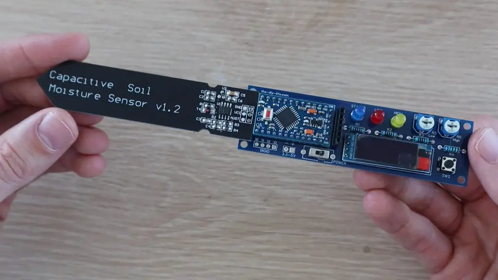
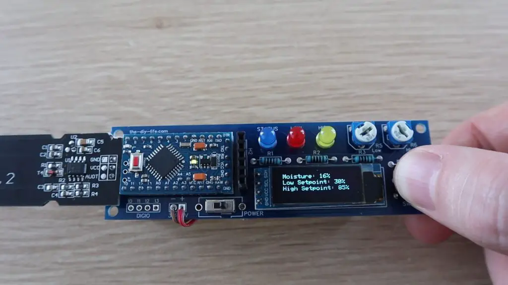
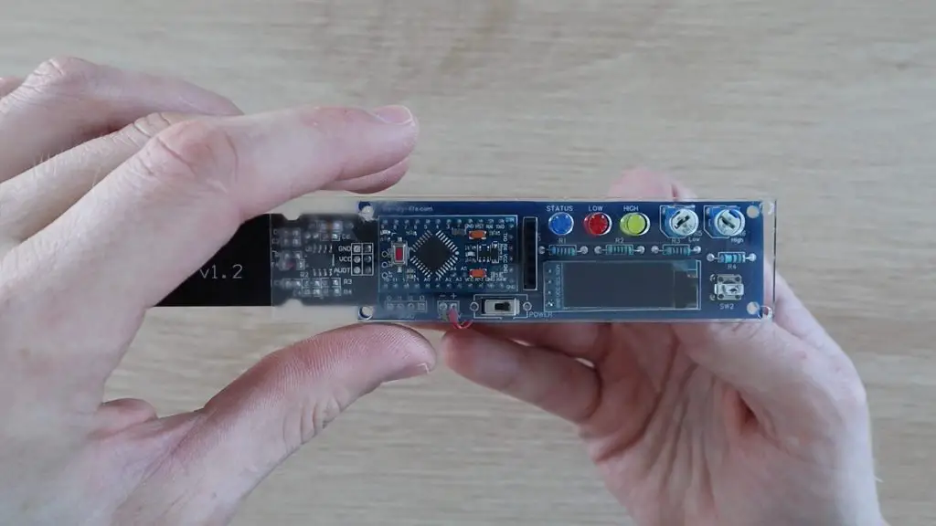
Do you often forget to water your indoor plants? Or perhaps you give them too much attention and over-water them. If you do, then you need to make yourself a soil moisture monitor. This Arduino based, battery-powered monitor uses a captive sensor to measure the moisture level of the soil it is stuck into and then flashes LEDs and provides an OLED display readout telling you whether you’re over or under watering your plant.
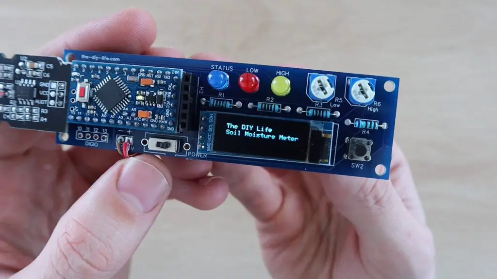
Two potentiometers on the monitor allow you to set a maximum and minimum moisture level which then activates either the red LED, to indicate a low moisture level, to tell you that you need to water your plant, or the yellow LED on a high moisture level, to tell you that you’re overwatering your plant. You can also push the button next to the display to turn on the OLED display and to see the exact moisture level as well as the two set points.
Here’s a video of the build and the monitor being turn on and used, read on for the step by step instructions to build your own.
What You Need To Build Your Own Soil Moisture Monitor
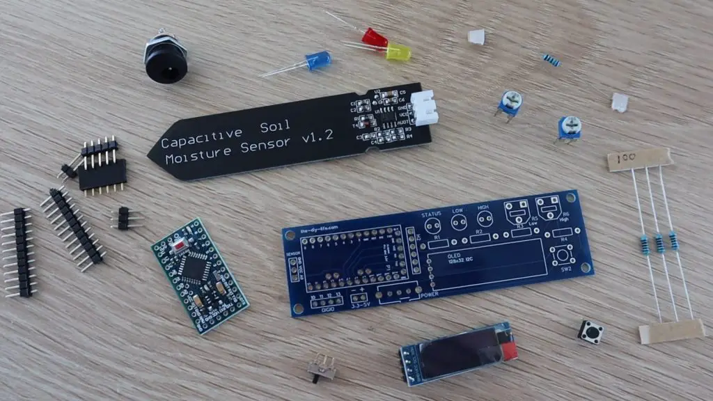
- 3.3V Arduino Pro Mini – Buy Here
- The 5V Version Can Be Used With A Different Battery & 220Ω LED Resistors
- USB Programmer – Buy Here
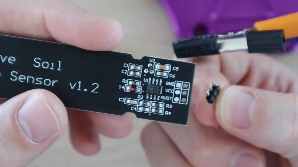
- Capacitive Soil Moisture Sensor – Buy Here
- 3 x 5mm LEDs (Preferably Different Colours) – Buy Here
- 10K Resistor – Buy Here
- 3 x 100Ω Resistors – Buy Here
- 2 x 10K Trim Pots – Buy Here
- Tactile Pushbutton Switch – Buy Here
- Slide Power Switch – Buy Here
- 128×32 I2C OLED Display – Buy Here
- Male Header Pins – Buy Here
- Female Header Pins – Buy Here
- Ribbon Cable – Buy Here
To Power The Monitor
How To Build Your Soil Moisture Monitor
Assembling The Electronics
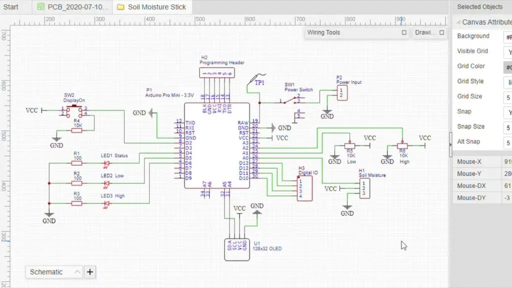
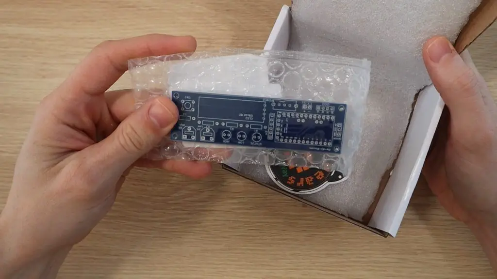
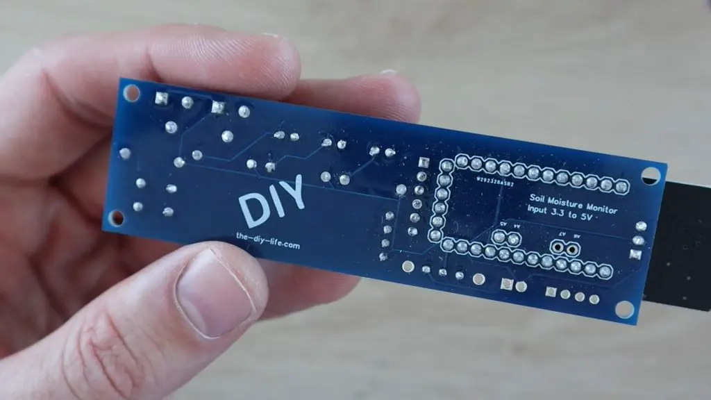
I started out by designing the circuit, with the intention of making it into a PCB. There are quite a few external components to this monitor, so a PCB helps make assembly easy, with fewer loose wires, and makes the monitor into a more robust device that can be mounted onto the moisture sensor spike.
If you don’t want to build the monitor onto a PCB, it can also be easily assembled onto a breadboard and you can just use the lead included with the capacitive moisture sensor to connect the sensor to the breadboard.
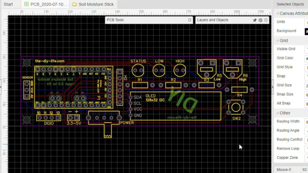
I ordered the boards from PCB Way, which charges only $5 for 5 basic PCBs up to 100 x 100mm. They were manufactured and shipped out just three days later and arrived in less than a week.
I was also really happy with the quality of the boards, they’re a lot better quality than the typical cheap PCBs available online.
I’d really recommend trying them out for your own PCBs. I’ve put links to my PCB files which you can order from PCB Way if you’d like to try build your own moisture monitor.
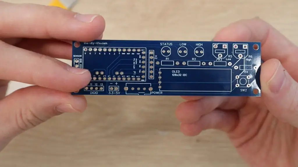
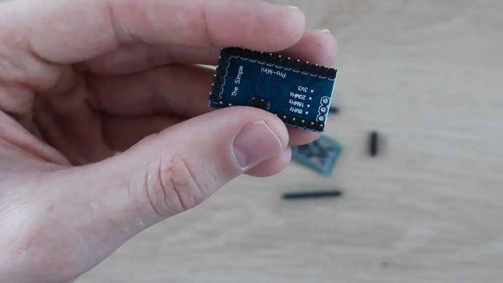
The board is designed for a 3.3V Arduino Pro Mini to be run on a single 18650 lithium battery, but you can also use a 5V Pro Mini, you’ll just need to use a higher voltage battery pack to supply the board and use 220Ω LED resistors.
If your Arduino Pro Mini came without the header pins attached, you’ll need to start by attaching them. Also, remember that this design needs the two analog pins A4 and A5 to communicate with the OLED display, so don’t forget to add these two pins as well.
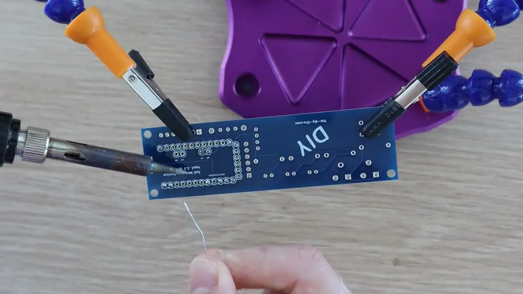
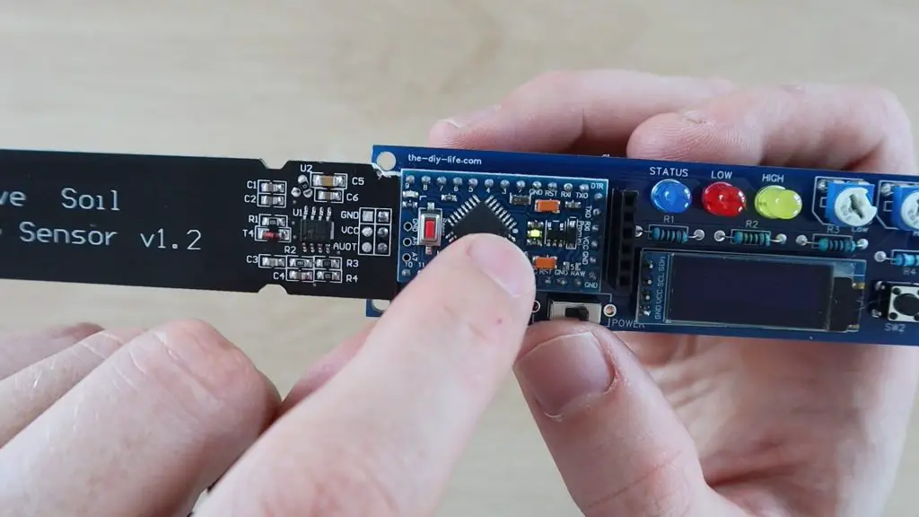
Solder the components into place on the circuit board, paying attention to the orientation of the LEDs and the tactile push-button.
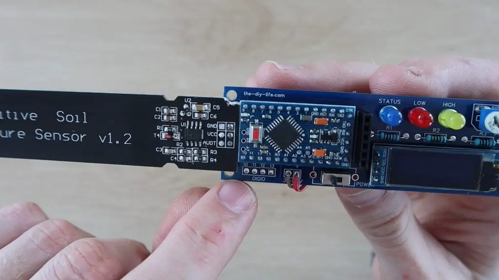
In order to connect the moisture sensor to your circuit board, you’ll need to remove the connector which comes pre-soldered onto the sensor. You can then add three male header pins and solder the sensor directly onto your circuit board.
Once you’re done, use some side cutters to clip the ends off of the header pins to make the board more compact.
Your soil moisture monitor is now complete and just needs a power source.
I powered my monitor using a single 18650 lithium cell mounted into one of these USB charging boards. You can use a different battery if you’d like or power your monitor using a USB charger or power bank.
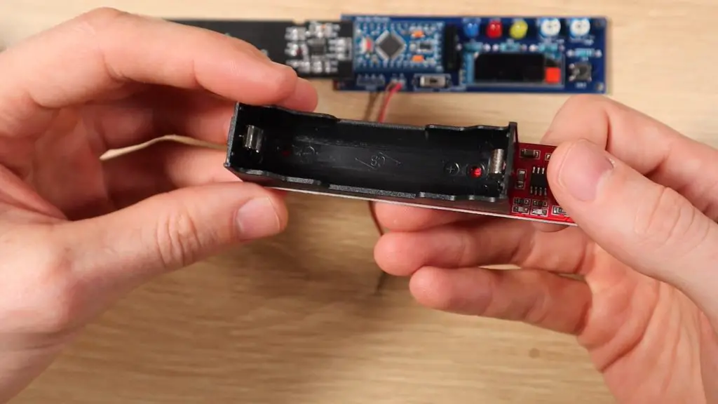
Connect your battery pack or power supply to the power supply terminals on the side of the circuit board, paying attention to the polarity.
If you’re using a single battery, or a compact battery pack, try glue the battery to the back of the circuit board so that it’s all one unit.
Programming Your Monitor
To program the Arduino Pro Mini, you’ll need to use a USB programmer. Plug jumpers between the programmer and the header strip on the circuit board, making sure that the programmer pins go to the correct Arduino pins and that you use the correct Vcc voltage pin on the programmer to suite the board you are using, 3.3V for the 3.3V Pro Mini and 5V for the 5V Pro Mini.
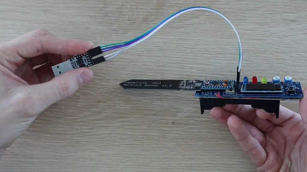
You’ll also need to use the programmer when you’re using Serial communication to transmit the sensor values to your computer in order to calibrate your moisture monitor.
Here is the code:
//The DIY Life
//Michael Klements
//31 July 2020

#include <SPI.h>                                  //Import the libraries required for the display and low power mode
#include <Wire.h>
#include <Adafruit_GFX.h>
#include <Adafruit_SSD1306.h>
#include <LowPower.h>

#define SCREEN_WIDTH  128                         //OLED display width, in pixels
#define SCREEN_HEIGHT 32                          //OLED display height, in pixels

#define OLED_RESET     -1                         //Reset pin # (or -1 if sharing Arduino reset pin)
Adafruit_SSD1306 display(SCREEN_WIDTH, SCREEN_HEIGHT, &Wire, OLED_RESET); //Create the display object

#define statusLED 4                               //Define the LED & sensor pins
#define lowLED 5
#define highLED 6
#define sensorPin 10                              //Only used for the additional low power settings

#define dryCal 1000                               //Define the wet and dry calibration limits
#define wetCal 500

#define buttonPin 2                               //Define the button pin number

#define moisturePin A0                            //Define the analog input pin numbers
#define lowSetPin A1
#define highSetPin A2

int moisture = 0;                                 //Create variables for the analog inputs
int lowSet = 0;
int highSet = 0;

int cycleCount = 0;                               //Create a counter to flash the status LED

void setup()
{
  Serial.begin(9600);
  display.begin(SSD1306_SWITCHCAPVCC, 0x3C);      //Connect to the display
  display.clearDisplay();                         //Clear the display
  display.setTextSize(1);                         //Normal 1:1 pixel scale
  display.setTextColor(SSD1306_WHITE);            //Draw white text
  display.setCursor(10,5);                        //Display splash screen
  display.print(F("The DIY Life"));
  display.setCursor(10,15);
  display.print(F("Soil Moisture Meter"));
  display.display();
  delay(2000);
  display.clearDisplay();                         //Clear display
  display.display();
  pinMode(statusLED, OUTPUT);                     //Set the pin modes
  pinMode(lowLED, OUTPUT);
  pinMode(highLED, OUTPUT);
  pinMode(sensorPin, OUTPUT);
  pinMode(buttonPin, INPUT);
}

void loop()
{
  updateValues();                                 //Call the function to update the analog input values
  if (digitalRead(buttonPin) == HIGH)             //If the button is pushed
  {
    while(digitalRead(buttonPin) == HIGH)         //While the button stays pushed
    {
      display.clearDisplay();                     //Display the analog input values
      display.setCursor(10,3);
      display.print(F("Moisture: "));
      display.print(moisture);
      display.print(F("%"));
      display.setCursor(10,13);
      display.print(F("Low Setpoint: "));
      display.print(lowSet);
      display.print(F("%"));
      display.setCursor(10,23);
      display.print(F("High Setpoint: "));
      display.print(highSet);
      display.print(F("%"));
      display.display();
      delay(1000);                                //Wait 1000ms between each display update
      updateValues();                             //Get updated analog input values, allows pots adjustments to be seen
    }
    display.clearDisplay();                       //When button is released, clear the display to turn it off
    display.display();
  }
  if(moisture<=lowSet)                            //If the soil moisture level is low, flash the low LED
  {
    digitalWrite(lowLED, HIGH);
    delay(50);
    digitalWrite(lowLED, LOW);
  }
  if(moisture>=highSet)                           //If the soil moisture level is high, flash the high LED
  {
    digitalWrite(highLED, HIGH);
    delay(50);
    digitalWrite(highLED, LOW);
  }
  if(cycleCount>=5)                               //Every 5 cycles, flash the status LED and reset the counter
  {
    digitalWrite(statusLED, HIGH);
    delay(50);
    digitalWrite(statusLED, LOW);
    cycleCount=0;
  }
  LowPower.powerDown(SLEEP_8S, ADC_OFF, BOD_OFF); //Enter low power mode for 8 seconds
  cycleCount++;                                   //Increment the cycle counter
}

void updateValues ()                                              //Function to update the analog input values
{
  //digitalWrite(sensorPin, HIGH);                                //LOW Power Mode - Turn the moisture sensor on
  //delay(200);                                                   //LOW Power Mode - Wait for it to power up and stabilise
  moisture = map(analogRead(moisturePin),wetCal,dryCal,100,0);    //Read the soil moisture measurement
  Serial.println(moisture);
  //delay(50);
  //digitalWrite(sensorPin, LOW);                                 //LOW Power Mode - Turn the moisture sensor off
  lowSet = map(analogRead(lowSetPin),0,1023,0,100);               //Read in the low setpoint pot value
  if (lowSet>=highSet)                                            //Make sure that the low setpoint cannot be greater than the high
    lowSet=highSet-1;
  highSet = map(analogRead(highSetPin),0,1023,0,100);             //Read in the high setpoint pot value
  if (highSet<=lowSet)                                            //Make sure that the high setpoint cannot be less than the low
    highSet=lowSet+1;
}We start by importing the libraries required for the OLED display and the low power mode. The library for low power mode is used to put the Arduino into a state where it uses less power than usual in order to prolong the battery life of the monitor.
We then set up the display parameters and create the display object.
We then define the LED and sensor PIN numbers. The sensorPin is only required for the additional low power settings which are explained later on.
We then have the wet and dry calibration set points, the button pin and then the analog input pin numbers.
Finally, we have variables to read in the analog inputs and a counter which is used to flash the status LED every 5 cycles.
In the setup function, we start Serial communication, which is used during setup to get the raw sensor values to set up the calibration, then connect to the display and show a splash screen. After two seconds of displaying the splash screen, we clear the display and then define the pin modes.
The loop function is quite simple. We call a function called updateValues to update the sensor and potentiometer readings, then check if the button has been pushed. If the button has been pushed, we then have a while loop which runs until the button is released again, which displays the soil moisture reading and potentiometer set points on the OLED display and updates the displayed values once every second.
When the button is released, the OLED display is turned off again to save power and the LED set points are then checked. If the soil moisture level is higher than the high set point, then the high LED is flashed and if the soil moisture level is lower than the low set point then the low LED is flashed.
We also have an if statement which flashes the status LED every 5 cycles or around 40 seconds to tell us that the monitor is still on. This is useful if you remove the Arduino’s power LED, are described in the additional low power settings, in order to further prolong battery life.
We then put the Arduino into a low power sleep for 8 seconds in order to save battery power and then increment the cycle counter.
The update values function reads in the soil moisture level and maps the reading between the two calibration values to a moisture level between 0 and 100%.
We also read in the two potentiometer set points and map them to a 0 to 100% range and have checks to ensure that the low set point can’t be set higher than the high set point and that the high set point can’t be set lower than the low set point.
Additional Low Power Settings
You’ll notice that there are a couple of lines which have bee commented out and some notes mentioning some further low power settings.
The current setup without any code or hardware modifications draws around 8-10mA. This means that a 4200mA battery will last around 20 days before needing to be recharged.
This can be extended by connecting the Vcc pin on the sensor to the Arduino’s digital IO pin 10 so that the sensor is only turned on during readings.
The sensor alone draws about 5mA, so turning it off for 8 seconds between readings dramatically increases the battery life. This will slow the code down a bit too as you’ll need to wait for the sensor to startup and stabilise before getting meaningful readings from it. This won’t really affect the normal operation of the monitor but will be noticeable when the OLED display is on, as you’ll need to wait longer for readings to update.
Another thing to do to further improve the battery life is to physically remove the Arduino’s green power LED or cut through the PCB trace to it to turn it off. This reduces another 2-3mA.
Doing both of the above modifications will allow this monitor to run for around 50-60 days on a single charge.
Using The Soil Moisture Monitor
When powering the soil moisture monitor on, you should first see the splash screen and then the display should turn off.
Once off, you can push the button and then wait a few seconds for it to finish the sleep cycle and then turn the display on. You can then see the actual measured moisture level and the two set points.
Calibrate The Wet & Dry Levels
Before you get meaningful information from the monitor, you’ll need to calibrate the wet and dry limits and update the values in the code.
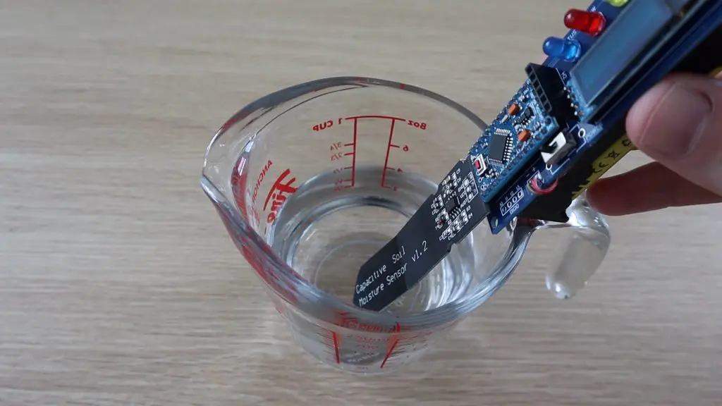
Use the USB programmer and your Serial monitor to display the raw sensor values being read on the analog input. Start by taking readings in dry air and then in glass or jug of water, making sure that you don’t submerge any of the components. Use the maximum and minimum values displayed as the two calibration limits in the code.
Try The Monitor Out
Once you’ve updated the calibration limits, you should be getting more meaningful results from your monitor. You can see the moisture level go up if you put your hand around the sensor.
Use a screwdriver to set the high and low setpoints on the two potentiometers.
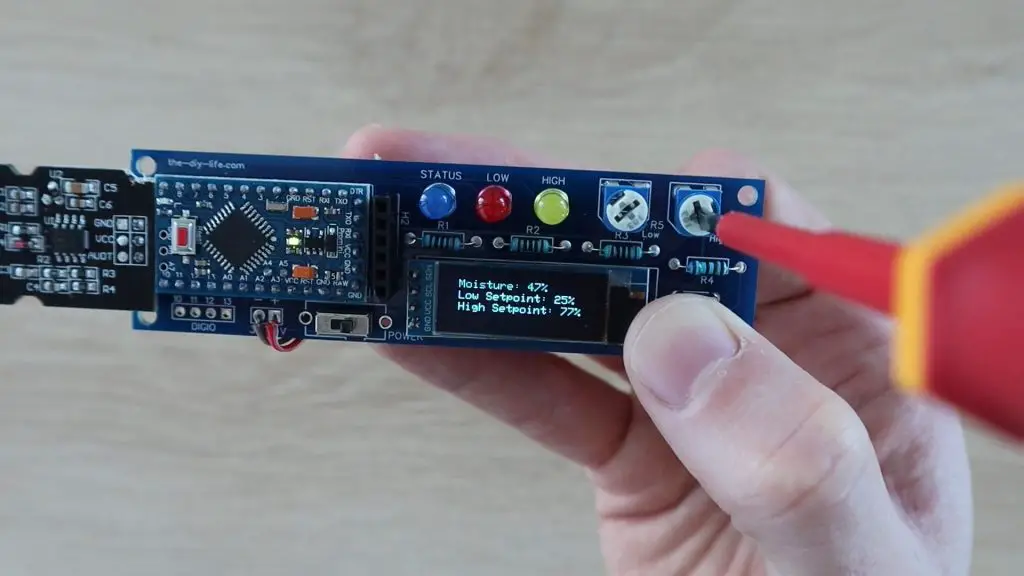
You’ll notice that you can’t set the high potentiometers lower than the low setpoint and likewise, you can’t set the low setpoint to be higher than the high set point.

Stick the sensor into the soil in your indoor plant, making sure that the soil does not touch the electronics, and then leave it for a few seconds to stabilise.
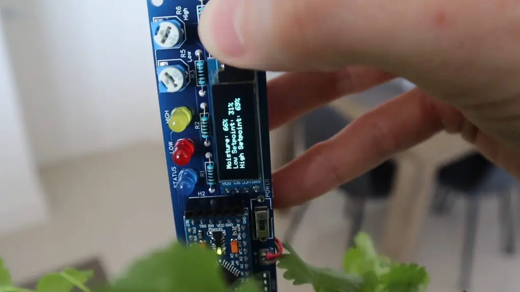
You should then get a soil moisture reading and you can start setting the correct set points depending on the type of plant you have. This may require some trial and error in the beginning as certain plants like more water than others.
I also added a simple acrylic faceplate to screw over the PCB to protect the electronic components from leaves and water droplets
Have you tried making your own soil moisture monitor? Let me know what you built and how you used it in the comments section below.
Share This Project

hey michael,
I am trying to order the PCB board, but have no idea how to start lol. is there a way I can just copy and paste yours some where? any help would be appreciated
thanks,
JD
Hi JD,
The .zip file for the PCB contains all of the files you need to order the PCB – referred to as a Gerber file. It contains a number of files which tell the manufacturer what each layer of the PCB should look like. You can use an online service to upload this combined .zip file for a quote. This is the one I used – https://www.pcbway.com/QuickOrderOnline.aspx
The website will auto-detect most of the settings, you might just need to choose your board colour and silkscreen colour (the text and guides printed onto it).
Hope this helps!
Thank you very much !
Hey Michael, board came out very well. I ordered the usb programmer you had in parts list. I noticed mine and yours is slightly different. I’m using 3.3v, so would I just match what the usb says, to the board and just skip out on the 5v, part of the programmer? If I match them it’s only 4 plugins. Thanks! First timer over here….
JD
Hi JD,
That’s great! The difference on the programmers is the DTR pin. I couldn’t find one exactly like the one I’ve used on Amazon. The one I used also has 3.3V and 5V and I’ve just left the 5V disconnected.
The DTR pin takes care of the reset before uploading the program to your Arduino, so you’ll need to press and hold the reset button on your Arduino, then click upload, keep the button pressed while compiling, and then release the button as the IDE starts saying uploading.
I am finished building it and i get the light on and the blinking light while the USB is in. I am using the Arduino Editor and am using the usb and the pro mini board 3.3 v 8mhz. it wont let me get the file uploaded, i keep getting Exit Status error at line 15 Adafruit ssd display width and height. any suggestions would be great thanks !
jd
Hey Michael,
Just wanted to let you know I completed everything and it works like a charm ! Sorry for all the comments, it was saying they didn’t send so I sent a lot!!!
Anyways thanks again and I really enjoy it !
JD
That’s great! Well done and no problem at all, that’s what the comments section is for!
Hey Michael I finished building and having trouble programming it says matching function for “ADafruit_ssd1306 display (screen width…..etc) any suggestions ? Thanks
JD
I am finished building it and i get the light on and the blinking light while the USB is in. I am using the Arduino Editor and am using the usb and the pro mini board 3.3 v 8mhz. it wont let me get the file uploaded, i keep getting Exit Status error at line 15 Adafruit ssd display width and height. any suggestions would be great thanks !
jd