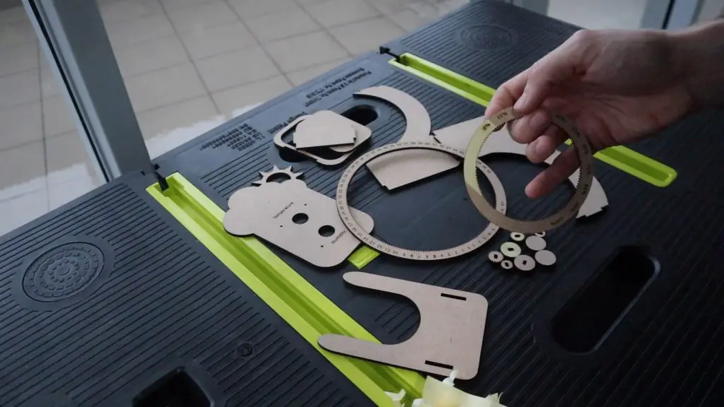
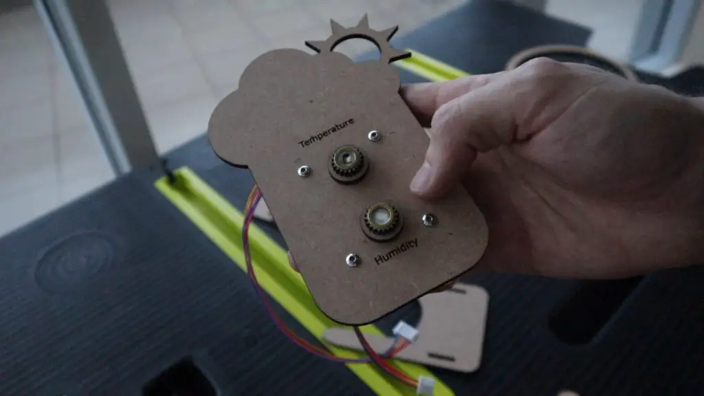
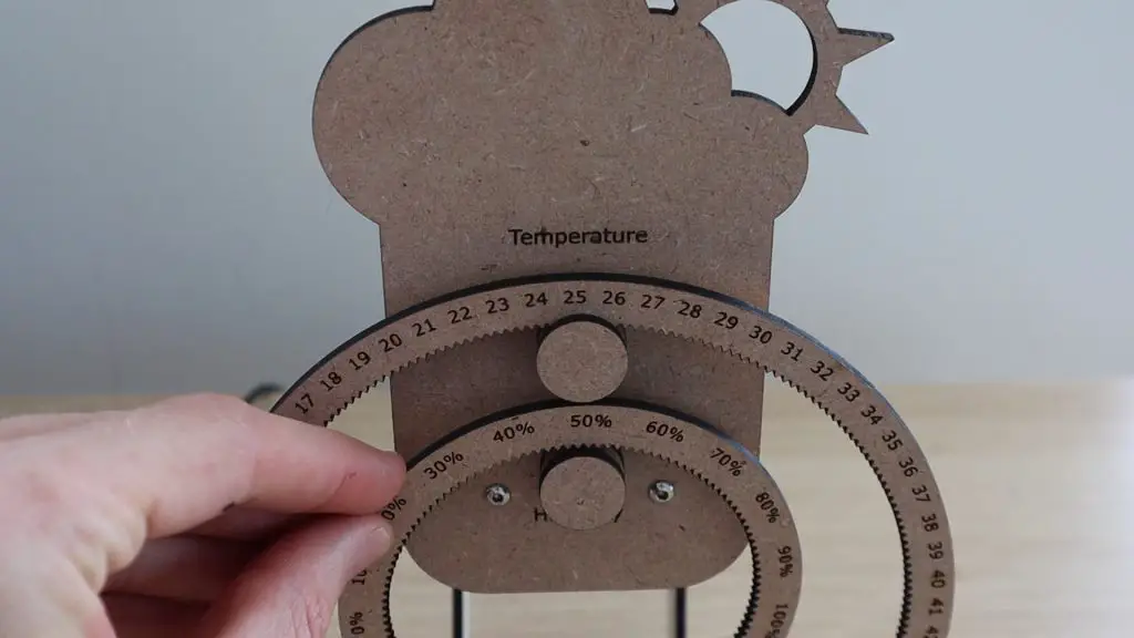
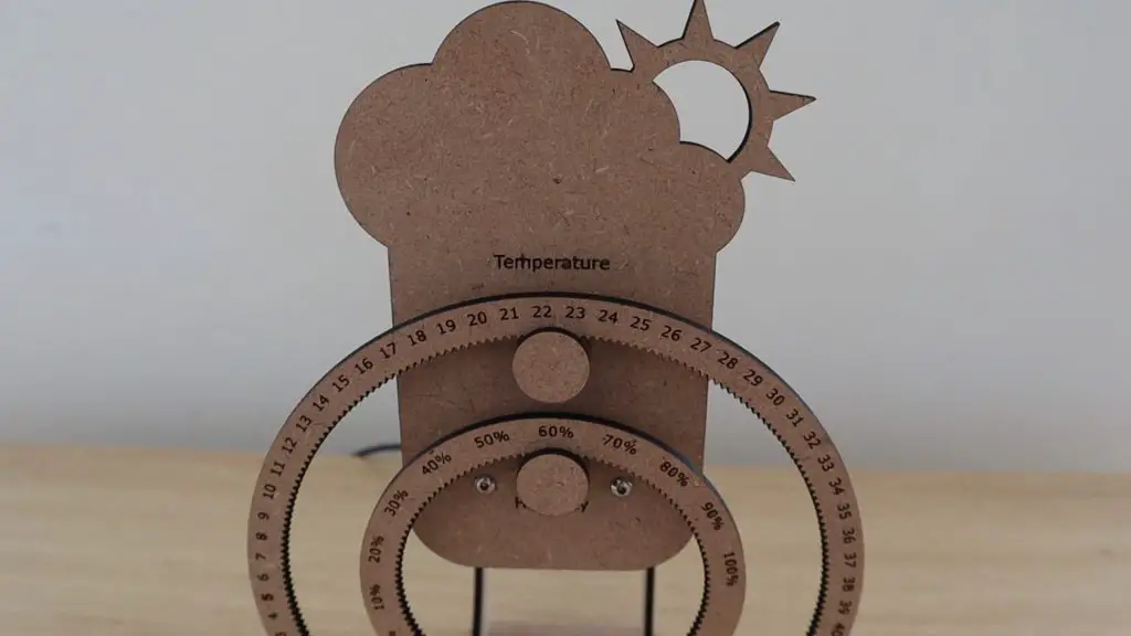
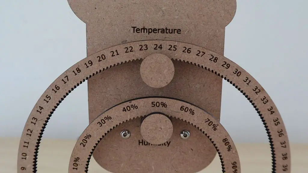
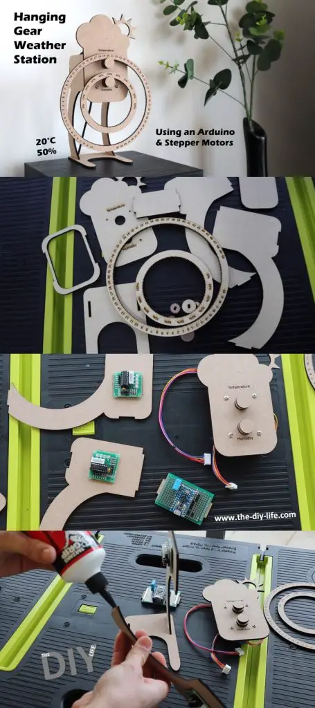
In this project, I’ll be showing you how to build your own hanging gear weather station, which is made from laser-cut MDF components. An Arduino Pro Micro uses a DHT11 sensor to take temperature and humidity measurements and then drives two stepper motors to turn the hanging gears to indicate the measured values.
The weather station is supported by two legs on a flat base, making it perfect to stand on your desk, or on a shelf or side table.
The DHT sensor has a range of 20-95% relative humidity and can measure temperatures between 0-50°C. I’ve designed the gears for the full humidity range and with a negative temperature range so that you can easily use a different sensor if you’d like to place the sensor outside to measure the outdoor conditions.
The stepper motors are almost silent and their noise level can be adjusted by slowing down their movement, so you won’t be bugged by them if you use the weather station on your desk.
Here’s a video of the build and weather station in operation:
What You Need To Build Your Weather Station
- 3mm MDF Board – Buy Here
- Arduino Pro Micro – Buy Here
- 2 x 28BYJ 48 Stepper Motors & ULN2003 Drivers – Buy Here
- 4 x M3 x 10mm Machine Screws & Nuts – Buy Here
- DHT11 Temperature & Humidity Sensor – Buy Here
- 10K Resistor – Buy Here
- 4×6 cm Prototyping PCB – Buy Here
- Male Header Pins – Buy Here
- Female Header Pins – Buy Here
Building Your Hanging Gear Weather Station
We’ll start off by laser cutting the MDF components, then assemble the electronics and install these onto the MDF components, then finish the assembly of the weather station and then finally program and set up the Arduino.
Laser Cut The MDF Components
I designed the laser cut components in Inkscape. The components are all on a single sheet in the download, so you’ll need to split them up to suit the bed size of your laser cutter.
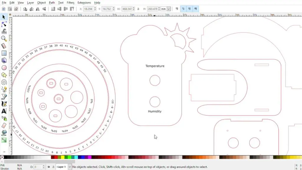
I used a cheap K40 laser cutter to cut and engrave these components. If you don’t have access to a laser cutter, consider using an online laser cutting service. There are a number of services available online and most will even deliver the components to you once they’re cut.
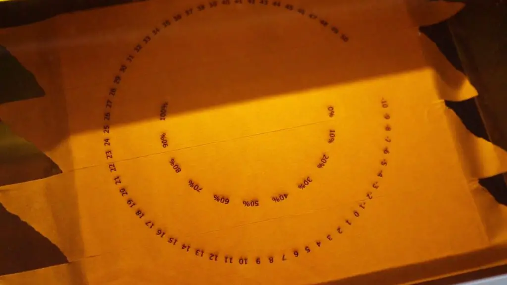
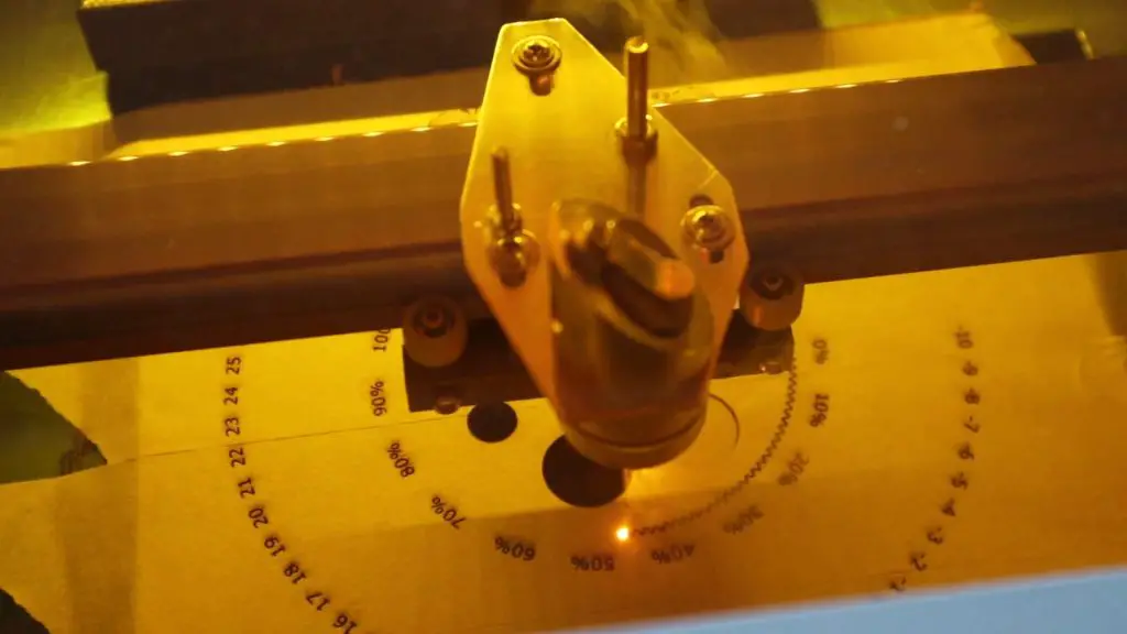
I started out by engraving and then cutting the gears. I always use masking tape over the MDF when engraving or cutting so that the smoke doesn’t mark the surface.
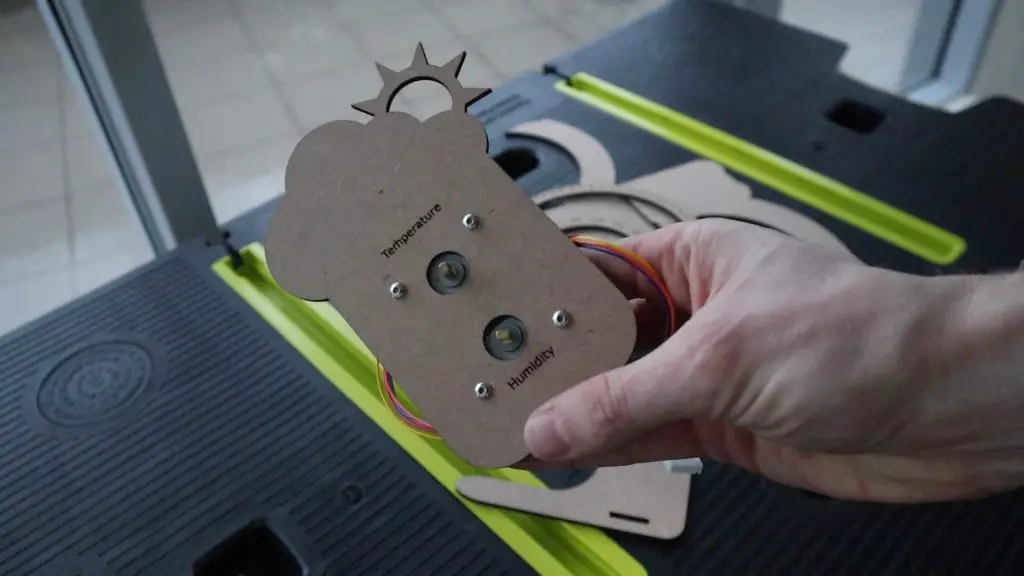
I then engraved and cut out the front panel, and finally cut out the remaining stand components.
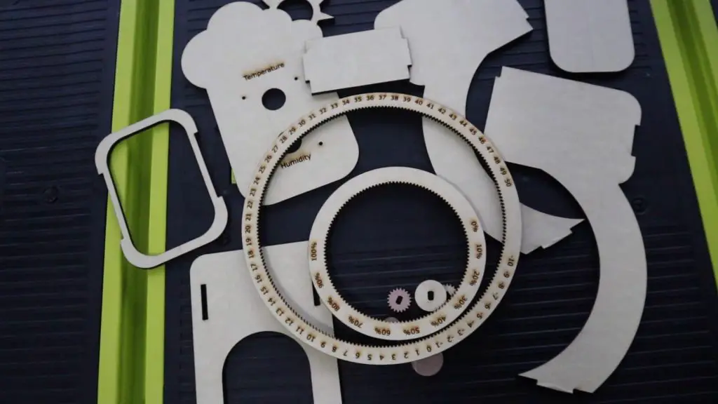
Once all of the parts have been cut, you’ll need to remove the masking tape from them.
Installing The Stepper Motors
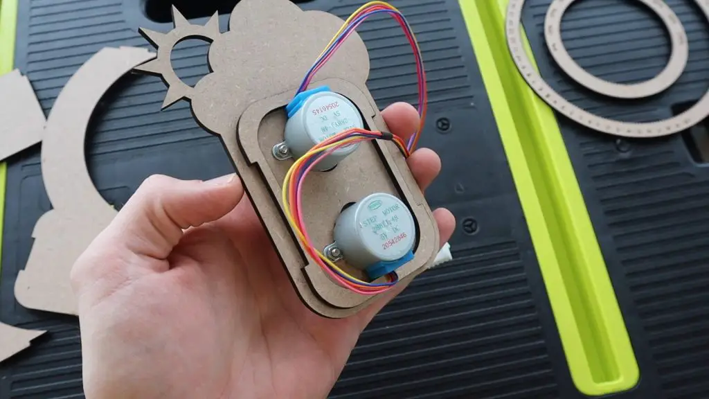
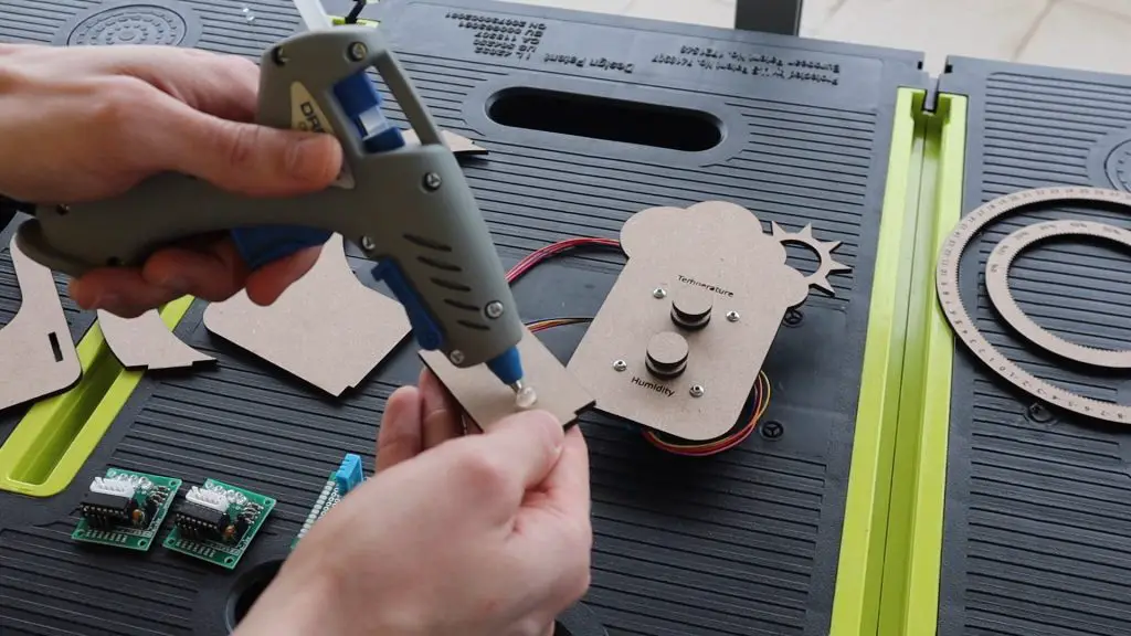
Next secure the two stepper motors to the front plate using two M3 x 10mm machine screws for each motor.
It’s a good idea to glue the stand support plate with the cutout for the motors to the back-side of the front panel before adding the motors, as it’s a bit easier than having to work around the motors later. It’s best to use wood glue to glue the MDF components together.
Next, you’ll need to assemble the gears.
Stack your gear pieces onto your servos with a drop of wood glue between each. Start with the disc with a hole in it and then the gear.
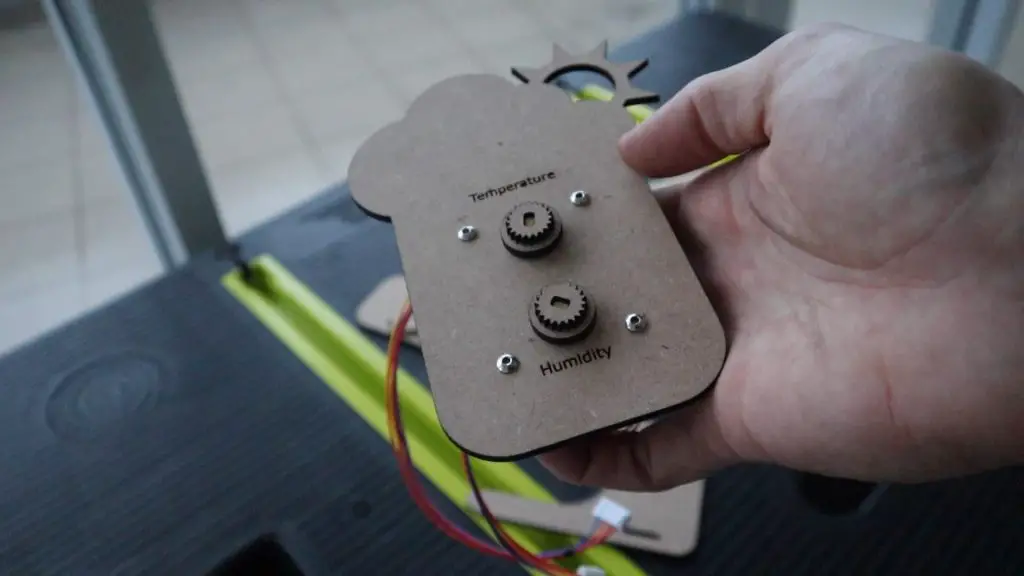
You’ll then need to add a small spacer between the gear and the front disc to create a bit of room for the gears to move freely. I used a flat washer for each of these. You could even use a small circle of thick card or plastic.

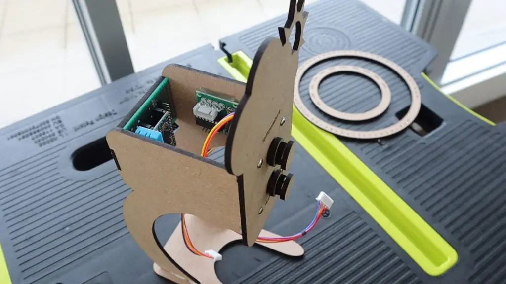
Assemble The Electronic Components
Here is a sketch of the connections between the Arduino and the DHT sensor and stepper motor drivers:
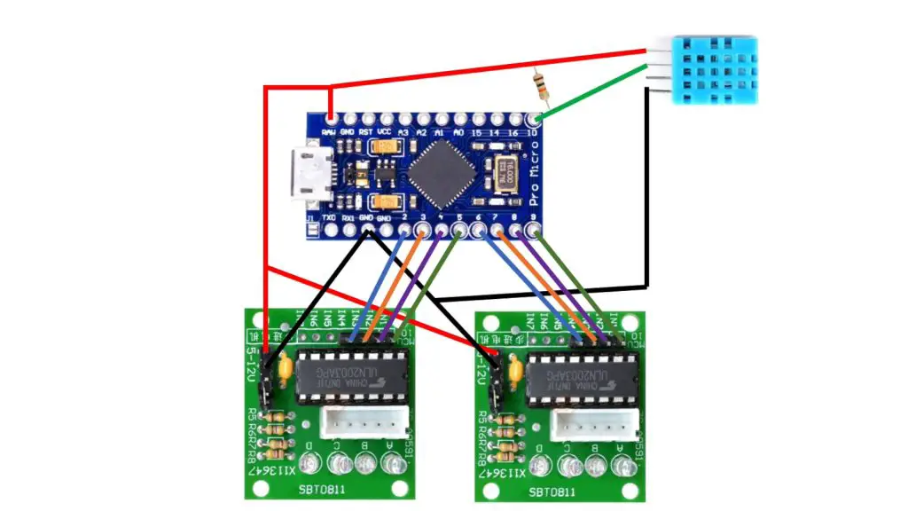
The circuit is quite simple and includes basic connections from digital IO pins 2 to 9 to the two stepper drivers and then a connection between the DHT11 sensor data pin and digital IO pin 10. You’ll also need to add your power connections to the sensor and stepper drivers as well as a 10k resistor between the connection to digital pin 10 and 5V.
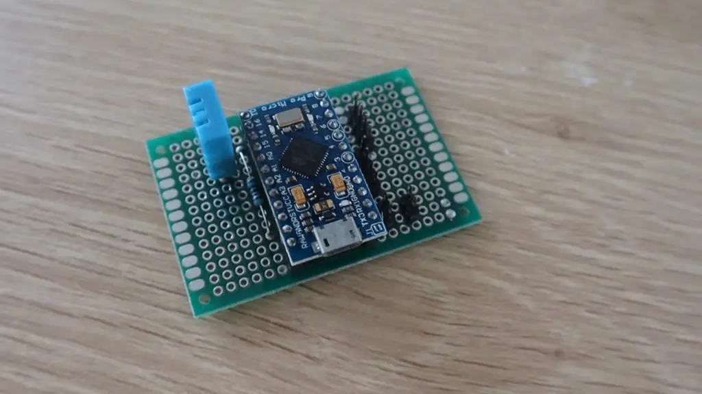
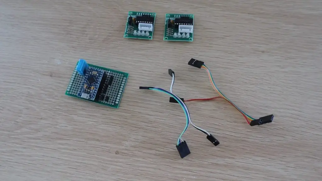
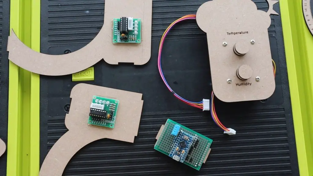
I assembled the header pin connections and DHT sensor onto a prototyping PCB so that the Arduino and stepper motor drivers could just be plugged into it.
I then made up some Dupont connector cables to connect the PCB and the stepper motor drivers. You can use jumpers or create your own header cables by soldering some ribbon cable to the female header pin connectors.
Now that the electronics are complete, let’s install them onto the MDF components and complete the assembly of the weather station.
Complete The Assembly Of The Weather Station
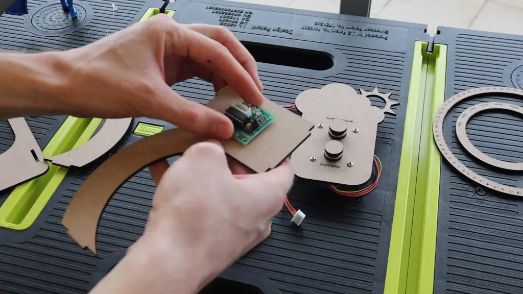
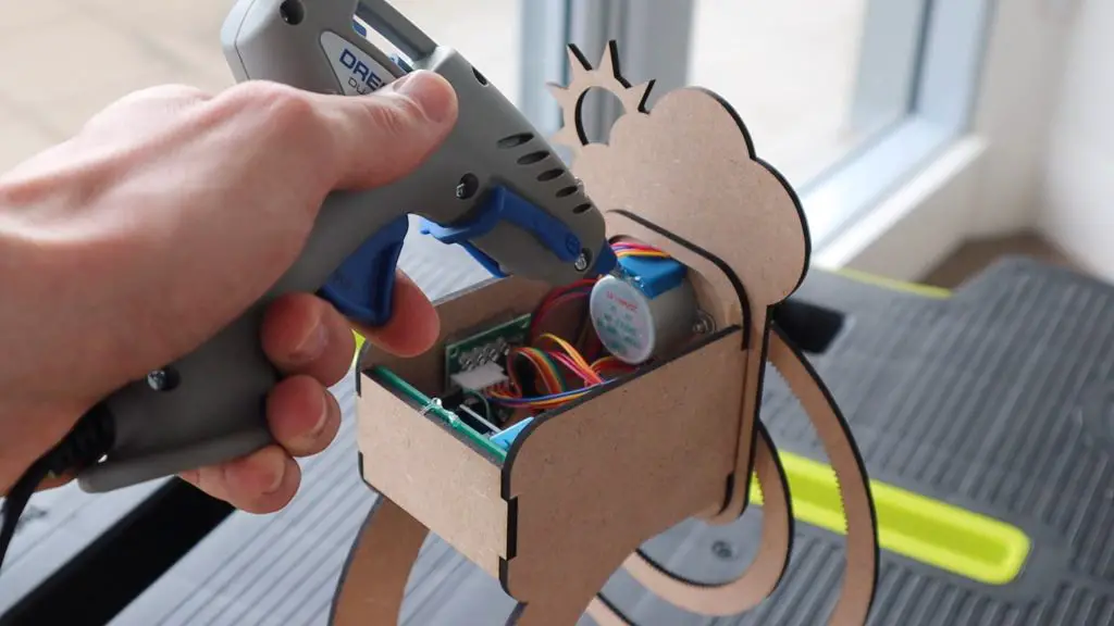
I used a glue gun to glue the Arduino PCB to the back plate of the weather station and the two stepper motor drivers onto the two side stand pieces.
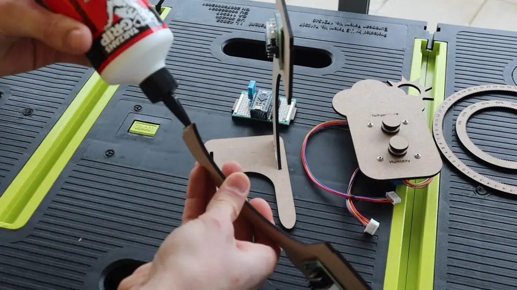
Once you’ve got the electronics glued into place, we can assemble the rest of the weather station using wood glue.
Glue the two legs into the base and then add the front plate onto the legs.
Finally, glue the back plate into place and allow the glue to dry. Make sure that the Arduino’s micro USB port is facing towards the base of the weather station.
Once the glue is dry, plug the stepper motors into the drivers and then connect the drivers to your Arduino using the cables you’ve made up.
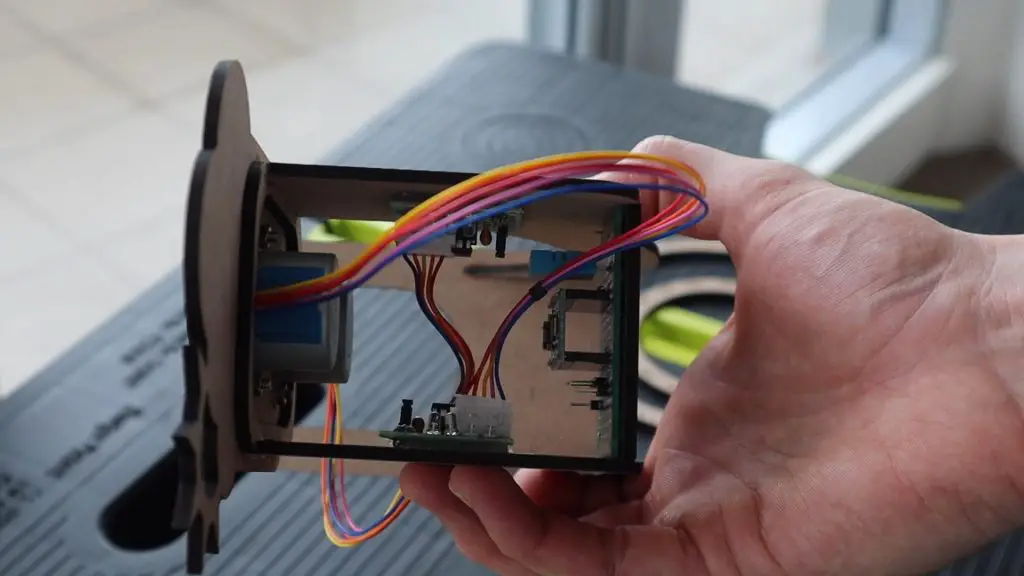
Try to tuck the cabling in so that it doesn’t hang out of the bottom or protrude out of the top of the back area.

If you’d like to close up the top, use the piece cut out of the support stand plate. Don’t glue this into place until you’ve tested out your stepper drivers and connections as you may need to access the cables again to make changes.
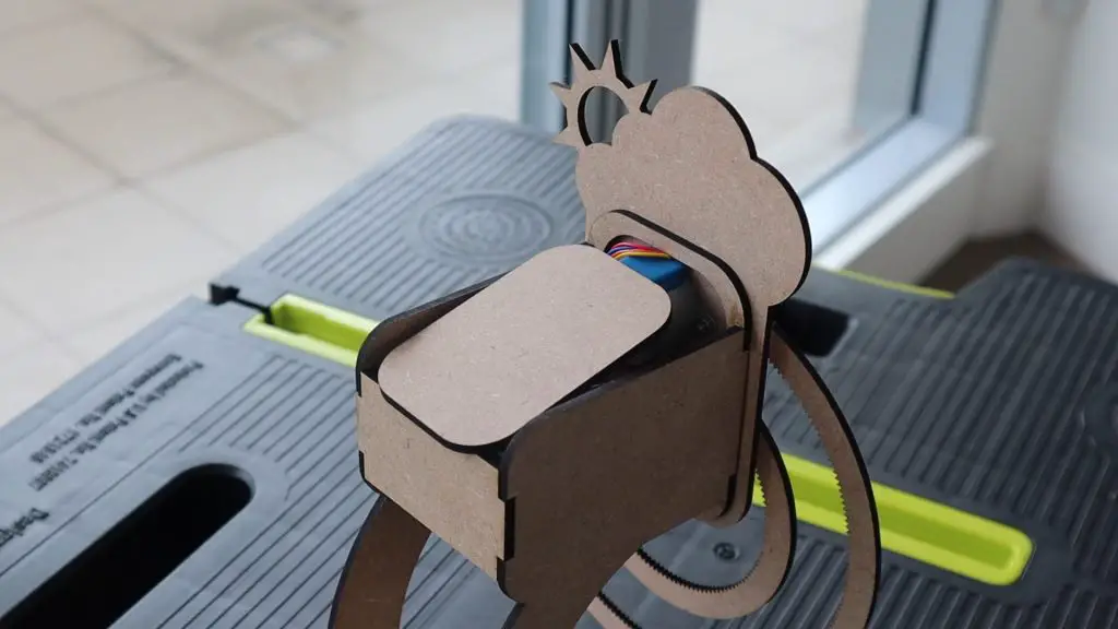
Plug your micro USB cable into the bottom of your weather station and you’re now ready to upload the code.
Programming Your Hanging Gear Weather Station
Now that your hanging gear weather station is built, you need to program the Arduino to take temperature and humidity measurements from the sensor and move the stepper motors to display the measured values.
Here is the sketch:
//The DIY Life
//Weather Station
//28 July 2020

#include "DHT.h"          //Import the required libraries for the sensor

#define DHTPIN 10         //DHT Sensor Pin
#define DHTTYPE DHT11     //DHT 11 Temperature & Humidity Sensor
DHT dht(DHTPIN, DHTTYPE);

int tempPins[] = {2,3,4,5};   //Define the temperature motor pins
int humidPins[] = {9,8,7,6};  //Define the humidity motor pins

int temp = 25;                //Create a variable for the temperature
int stepsPerDeg = 338;        //The number of motor steps for 1 degree celcius on the gear
int humid = 50;               //Create a variable for the humidity
int stepsPerPer = 69;         //The number of motor steps for 1 percent on the gear
int movementSpeed = 30;       //The motor movement delay in milliseconds

void setup(void)
{
  Serial.begin(9600);         //Used initially to display measured values
  for (int i = 0; i <= 3; i++)
  {
    pinMode(tempPins[i], OUTPUT);   //Assign the motor pin functions
    pinMode(humidPins[i], OUTPUT);
  }
  dht.begin();                      //Connect to the DHT Sensor
  delay(2000);
}

void loop(void)
{
  float startTime = millis();
  int newTemp = dht.readTemperature();   //Read in the current temperature
  int newHumid = dht.readHumidity();     //Read in the current humidity
  Serial.println(newTemp);               //Display values on serial monitor
  Serial.println(newHumid);
  int tempDiff = newTemp-temp;           //Calculate the difference between the actual indicated values
  int humidDiff = newHumid-humid;
  temp = newTemp;                        //Set the current values to the updated values
  humid = newHumid;
  int tempSteps = abs(stepsPerDeg*tempDiff);  //Calculate the number of motor steps to get to the new value
  int humidSteps = abs(stepsPerPer*humidDiff);
  bool tempDir = 0;                      //Create variables for the motor movement directions
  bool humidDir = 0;
  if (tempDiff < 0)                      //Set the motor movement directions
  {
    tempDir = 1;
  }
  if (humidDiff < 0)
  {
    humidDir = 1;
  }
  moveMotors(tempSteps, tempDir, humidSteps, humidDir);   //Call the moveMotors function to move the two motors
  float endTime = millis();
  if (endTime-startTime < 5000)    //Wait at least 5 seconds between updates
    delay(5000-(endTime-startTime));
}

void moveMotors(int tempSteps, bool tempDir, int humidSteps, bool humidDir)
 //Function to move motors
{
  for(int i=0; i<tempSteps ; i++)      //Move the temperature motor the required number of steps
  {
    static byte out = 0x01;
    if (tempDir)                       //Set the temperature motor direction
    {
      out != 0x08 ? out = out << 1 : out = 0x01;
    }
    else
    {
      out != 0x01 ? out = out >> 1 : out = 0x08;
    }
    for (int i = 0; i < 4; i++)        //Ring out the motor movement
    {
      digitalWrite(tempPins[i], (out & (0x01 << i)) ? HIGH : LOW);
    }
    delay(movementSpeed);              //Wait the delay time between steps
  }
  for(int i=0; i<humidSteps ; i++)     //Move the humidity motor the required number of steps
  {
    static byte out = 0x01;
    if (humidDir)                      //Set the humidity motor direction
    {
      out != 0x08 ? out = out << 1 : out = 0x01;
    }
    else
    {
      out != 0x01 ? out = out >> 1 : out = 0x08;
    }
    for (int i = 0; i < 4; i++)        //Ring out the motor movement
    {
      digitalWrite(humidPins[i], (out & (0x01 << i)) ? HIGH : LOW);
    }
    delay(movementSpeed);              //Wait the delay time between steps
  }
}We start by importing the library for the DHT11 sensor. We then assign the sensor pin and create a sensor object using the correct sensor type.
We then assign the pins for the two stepper motor drivers.
We then create variables for the temperature and humidity measurements as well as two values for the number of steps the stepper motors need to make in order to move the temperature gear by one degree and the humidity gear by one percent.
The values set as the temperature and humidity here are the initial values that should be set when you place the gears onto the motors before powering up the weather station. The gears will then move to the correct measured values from these starting values. You can make adjustments to these values if you’d like to more accurately suit the measured values you expect.
We also have a motor movement speed. The speed is essentially a delay between steps in milliseconds, so a higher value is a slower speed.
In the setup function, we start serial communication, which is used to see what the actual measured values are in order to compare them with what is displayed during the initial calibration and setup.
We then assign the stepper motor driver pins numbers and then connect to the DHT sensor.
In the loop function, we record the start time for the cycle. Then take a new temperature and humidity measurement. We display these on the serial monitor and then calculate the difference in temperature and humidity from the last measurements taken. We can then replace the old measurements with the new measurements.
We then take the differences and convert them into a number of steps required to get to that indication on each gear, then set the directions of motor movement and then call a function called moveMotors to move each of the motors the required number of steps and in a particular direction.
Finally, we check to see that at least five seconds have passed between each update. If not, because neither gear moved in that cycle, the delay waits out the additional time until 5 seconds have passed. This delay can be increased or decreased depending on how quickly your environment is likely to change. If you’re in a large room of outdoors then you could change the update time to be every couple of minutes rather.
The move motors function just rings out the movement of each motor by the required number of steps and in the required direction, with a short delay between each pulse to slow the motors down.
That’s the code, now let’s see how it works.
Setting Up And Using The Weather Station
Before you upload the code, place the two gears onto the motors, setting them to indicate the values set up initially in the code, these were 25°C and 50% humidity in my code.
You can then upload the code.
If you open up your serial monitor, you’ll see the first measurement taken by the sensor and the motors will then start moving the gears to get to these values from the initial values. Mine were 22°C and 62% relative humidity.
Once the movement finishes, you should see a second set of values and the gears may move again.
It usually takes a couple of minutes for the sensor readings to stabilise and you’ll then get move consistent data and less movement of the gears.
Calibrating The Gear Movement
If you notice that your displayed values are not the same as those shown in the serial monitor, first check that your motor movement directions are correct, then check your initial values are correct. If both of those are correct, you may need to make adjustments to the number of steps per degree or percent values in order to calibrate your weather station.
To do this, set the gear you’re calibrating to a known position, say 0°C or 0% humidity, and then set the corresponding motor to move a certain number of steps, the more the better. I’d suggest using around 5000 steps for each as a starting point. Wait for the motor to move the set number of steps and then make a note of the finishing position. In order to calculate the stepsPerDeg or stepsPerPer, simply divide the total number of steps moved by the motor by the number of degrees or percent moved on the gear.
For example, if I set my temperature motor to move 5000 steps and it moved from 0°C to 14.8°C, then my stepsPerDeg value should be 5000/14.8 = 338. Meaning that the motor needs to move 338 steps to move the temperature gear by one-degree celsius.
That’s it! Your weather station can now be set up on your desk or shelf to indicate the current temperature and humidity.
Let me know in the comments section if you’ve built a weather station before and what you used to display the values.
Share This Project
Ciao,intanto ti ringrazio per la condivisione di questo splendido progetto.
Stò iniziando i preparativi al taglio laser, ma mi sono accorto che il file scaricato è diverso dal progetto che stai montando.
Ho dedotto che il file da scaricare è di una versione più vecchia dove i rotori dei motori stepper non uscivano abbastanza dalla stazione, quindi hai modificato il progetto ma non il file.
E’ corretto?
grazie!
Hi Massimo,
That’s great, enjoy the build! I haven’t made any modifications to the project, the downloadable file is for the parts I used in the build as well.
Hello Michel, I find your project very interesting. For a school project we are in the process of realizing this one. Here comes the problem we have an arduino error when compiling the projects and we are unable to localize the problem, maybe you could help us. When compiling the programs this appears.
In file included from D:\Justin\Documents\Arduino\libraries\DHT_sensor_library-1.4.3\DHT_U.cpp:15:0:
D:\Justin\Documents\Arduino\libraries\DHT_sensor_library-1.4.3\DHT_U.h:36:10: fatal error: Adafruit_Sensor.h: No such file or directory
#include
Hi Justin,
It looks like your Arduino IDE doesn’t have the required libraries installed. Try searching for and installing them in the library manager.