In this tutorial, I’m going to be showing you how to connect up to 992 servos to an Arduino by using these 16 channel PCA9685 PWM drivers, which are controlled over the I2C interface. Each one of these boards can drive up to 16 servos or PWM outputs and you can chain up to 62 of them together, meaning that you could drive up to 992 servos – all controlled by just two pins on your Arduino. They’re also relatively inexpensive, there are good quality ones available for around $10 online, but you can also find ones from just $2-$3 each if you’re prepared to wait a bit longer for shipping.
Here’s a video summary of the tutorial and servos in operation, read on for the step by step instructions and the code:
What You Need For This Tutorial
- Arduino Uno – Buy Here
- 16 Channel PWM Driver – Buy Here
- Micro Servos – Buy Here
- Ribbon Cable – Buy Here
- Female Pin Header – Buy Here
- Male Pin Header – Buy Here
- 5V 5A Power Supply – Buy Here
How To Connect & Drive Your Servos
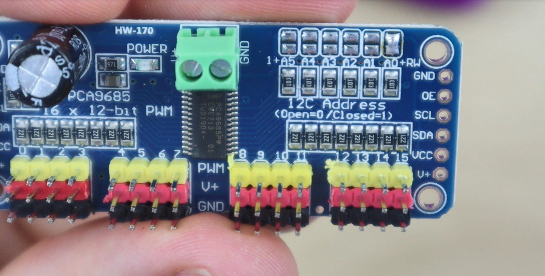
Each board has two sets of control input pins, one on each side. You can use either set of control inputs to connect your board to your Arduino, but they’re primarily useful to chain the drivers together. Each board can be plugged into the pins on the board before it, with the first connected to your Arduino.
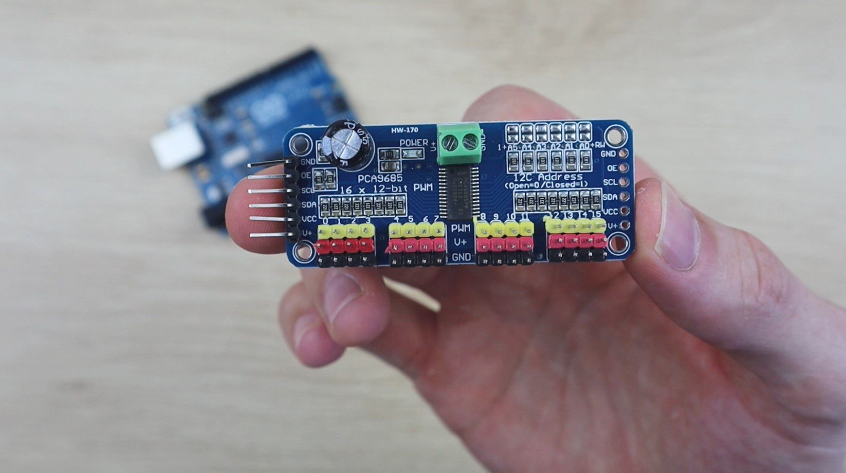
Each board also has two power terminals at the top to provide a dedicated 5-6V power supply to the outputs and then the 16 outputs along the bottom. What’s also nice about these boards is that they’re already set up to accommodate the 3 pin servo plugs. So you can plug your servos directly into the board instead of needing additional wiring like you’d need if you were plugging the servo directly into your Arduino.
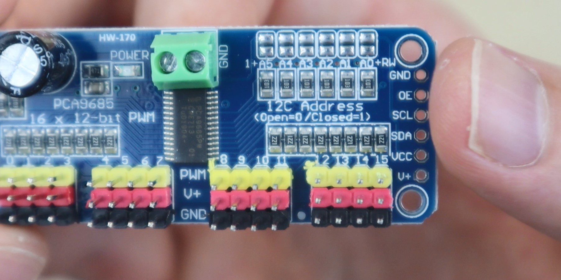
On the top right of each board is a set of bridgeable address jumpers which allow you to bridge different combinations to create a unique address for up to 62 different boards. To change the address of a board, you just need to solder a bridge across the two address terminals. This changes the address as follows:
- Board 0 – Address Terminals 000000 (no jumpers used) – Address 0x40
- Board 1 – Address Terminals 000001 (solder jumper over A0) – Address 0x41
- Board 2 – Address Terminals 000010 (solder jumper over A1) – Address 0x42
- Board 3 – Address Terminals 000011 (solder jumpers over A1 & A0) – Address 0x43
- And so on…
You can also use these boards to control LEDs, so you can control 992 LEDs individually and control their brightness as well. Although each channel is completely independent, each board must operate at the same PWM frequency. This means that if you’d like to use a combination of LEDs and servos, you’d likely need to split them up across two boards because servos typically operate at 50Hz and LEDs at 1kHz. Also, keep in mind that the maximum current output per pin is 25mA and there are already 220 home resistors in series with all of the PWM pins.
Have a look at this 7 segment display clock which was built using these PCA9685 servo drivers.
Connecting The Boards Together & To Your Arduino
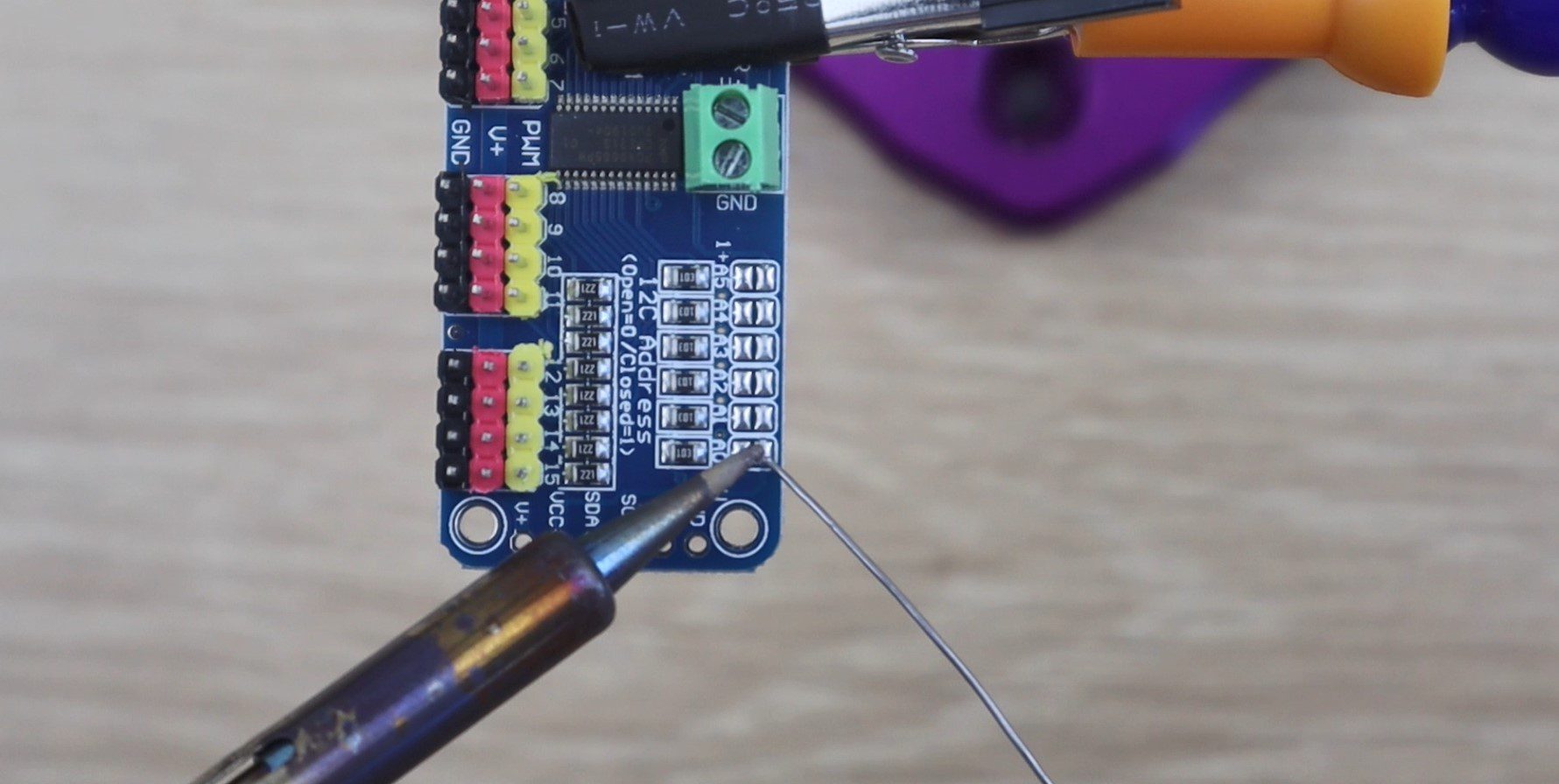
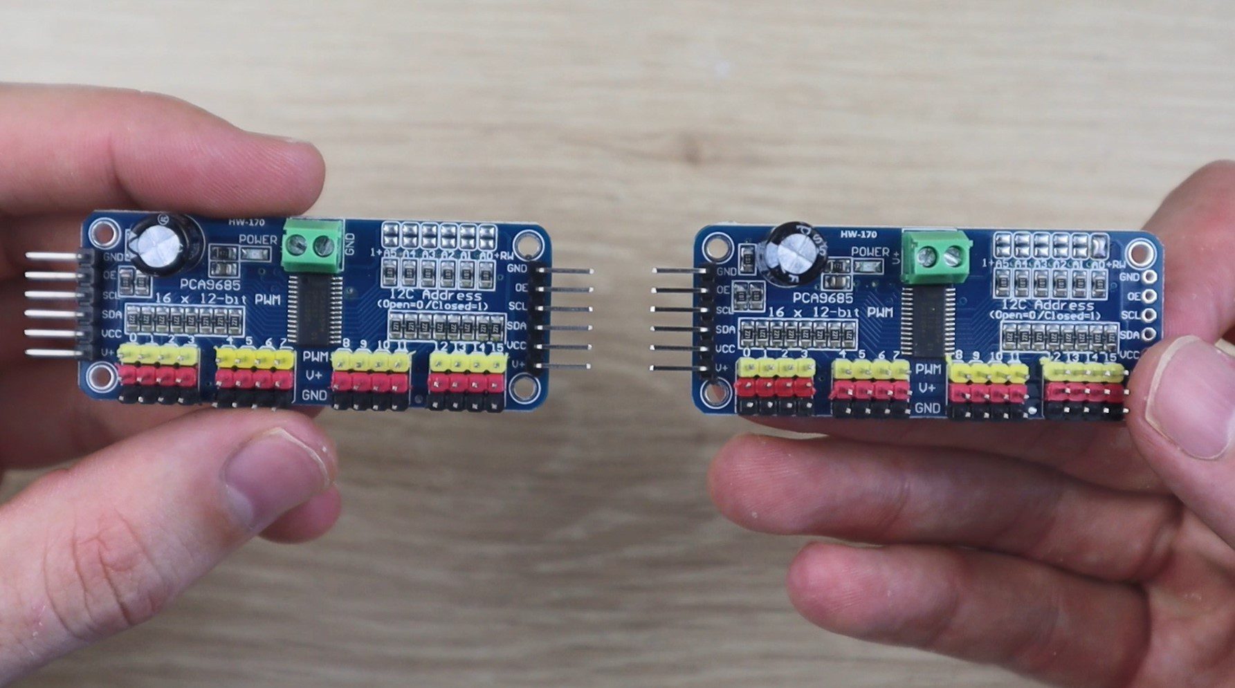
To chain two boards together, we’ll need to add some pins to the right side of the board to plug the next board into.
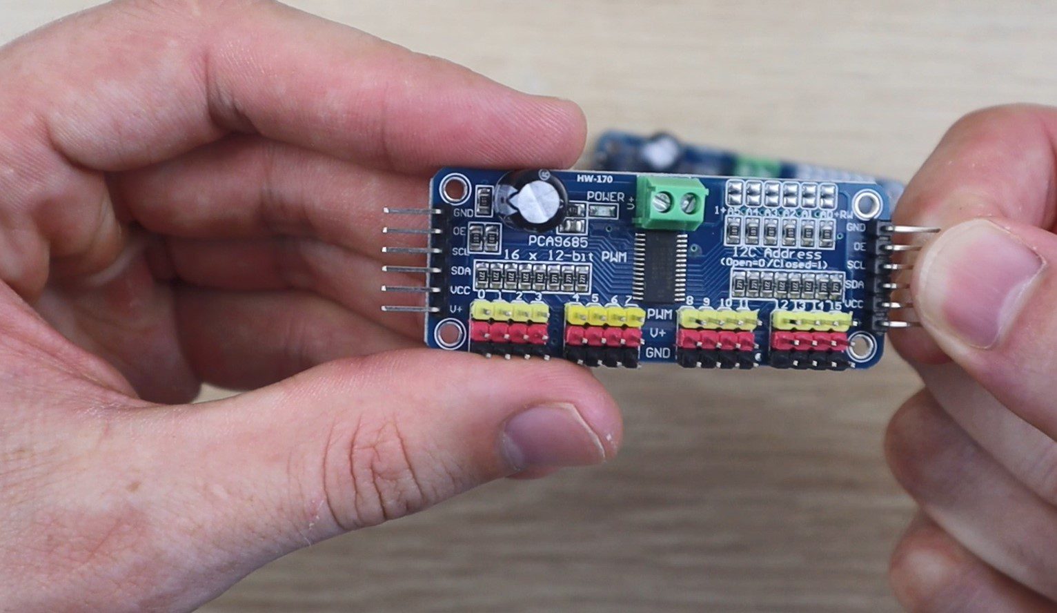
We’ll then bridge the first terminals on the right to change the address on the second board so that our Arduino can differentiate between the two.
Looking at the back of the board, the board accepts two supply voltages, one between 3 and 5 volts for the logic or onboard chip and the second up to 6V which is to supply the output pins. There is also a note to say that the terminals at the top have reverse polarity protection while the input on the side through the control pins does not.
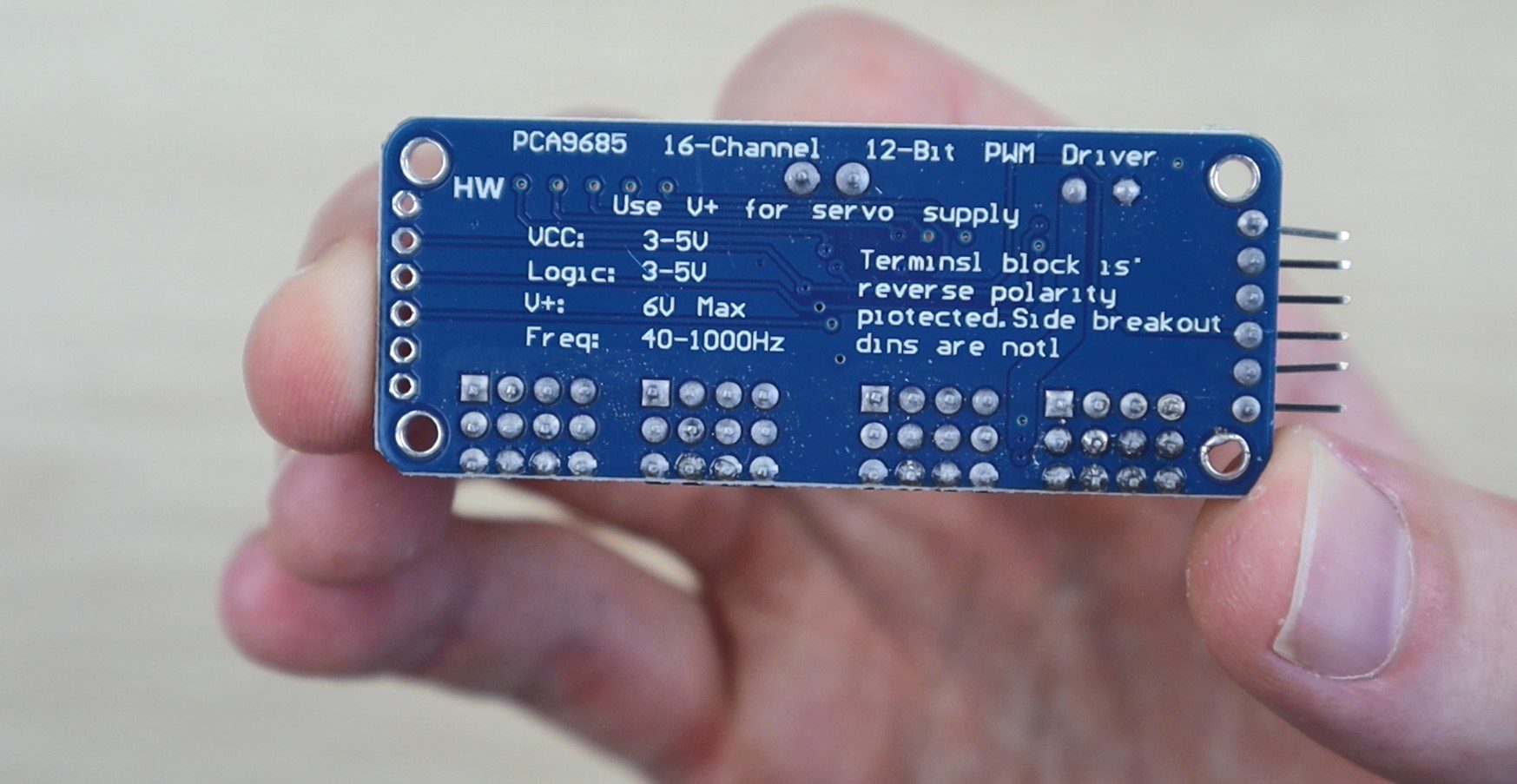
The power supplied through the terminals is fed to the V+ control pin, meaning that you don’t need to connect every board in the chain through the terminals, unless you’re drawing a lot of current on each.
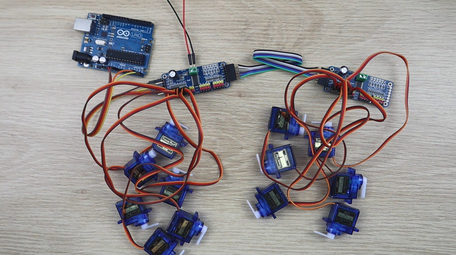
Now that we’ve added the second set of control pins and changed the address on the second board, we need to create a ribbon cable connector to join the two boards together. You only need to connect 4 pins to your Arduino and between each board, the ground, the two I2C pins and the logic supply voltage VCC. The other two pins, OE and V+ are used to enable or disable the boards and to supply voltage to the output pins. I’ve created ribbon cable to connect all six pins between the boards so that the output voltage is fed to the second board and so that I can use the enable pin in future if needed.
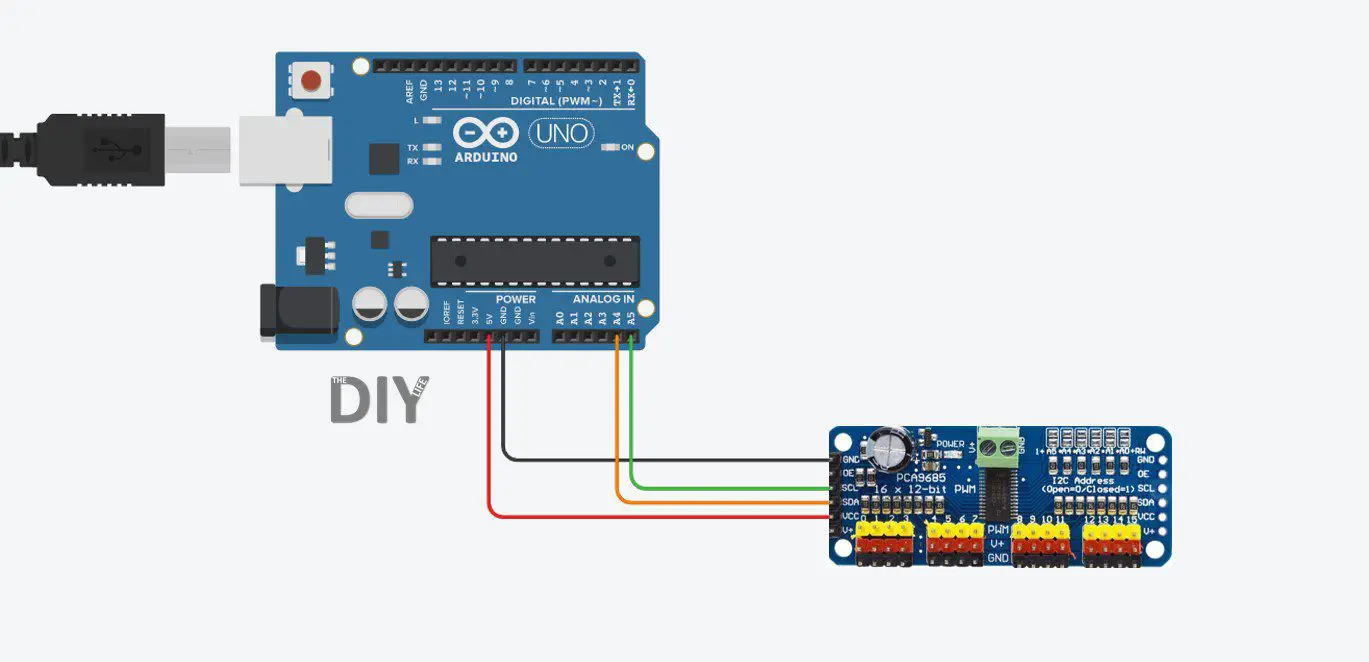
When connecting your PWM drivers to your Arduino, make sure that you use the correct I2C pins.
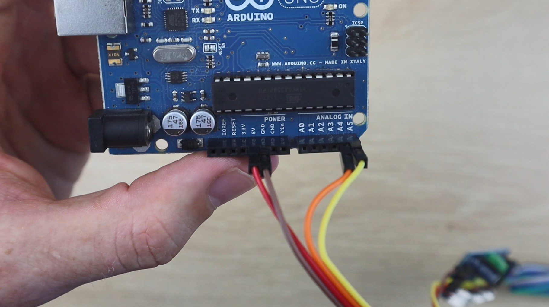
This is through analogue pins 3 and 4 on older Arduino Uno’s, through digital pins 20 and 21 on older Megas and through the dedicated SDA and SCL pins on later model Unos, Megas and Leonardos. Remember that Vcc is only to supply the logic circuits on the drivers, not the outputs. To drive the outputs it is recommended that you use a dedicated supply through the terminals.
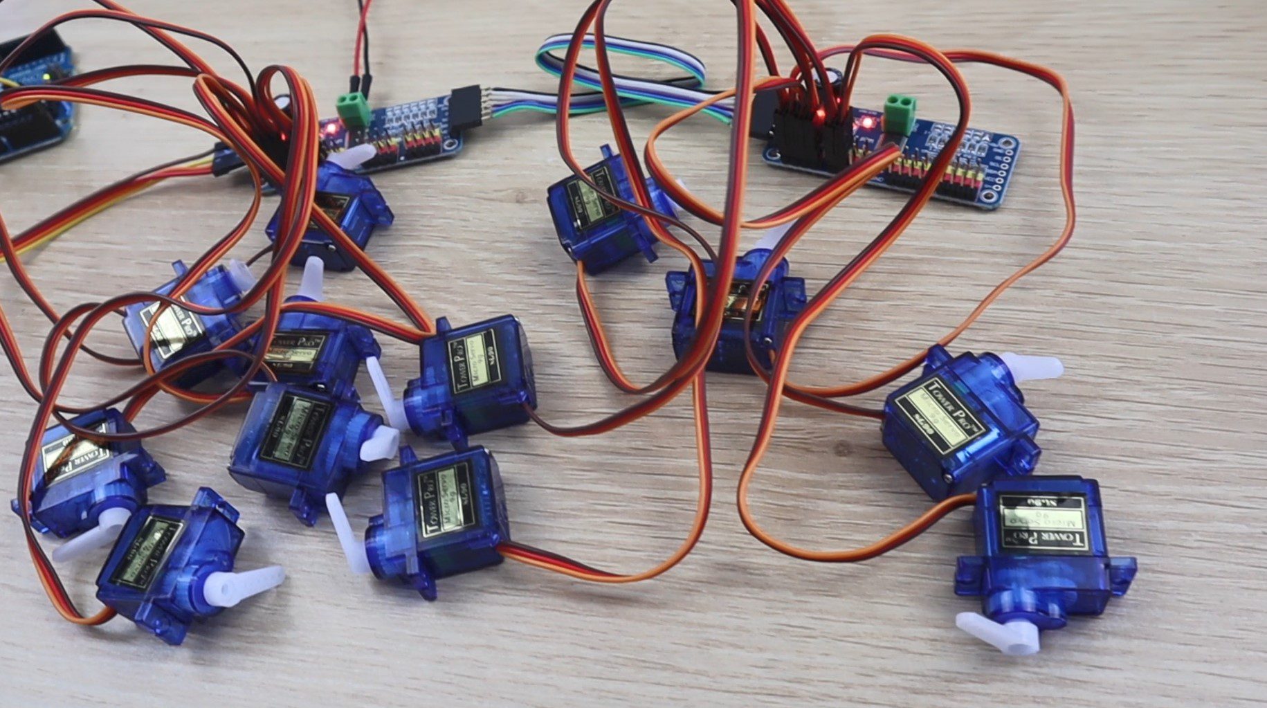
Now go ahead and plug your servos into the output pins on your boards. Make sure that the plugs are put in the correct way around, with the brown wire being ground and the orange wire being the PWM signal.
Programming Your Arduino To Control The Servos
Now let’s have a look at the code and how to control each servo.
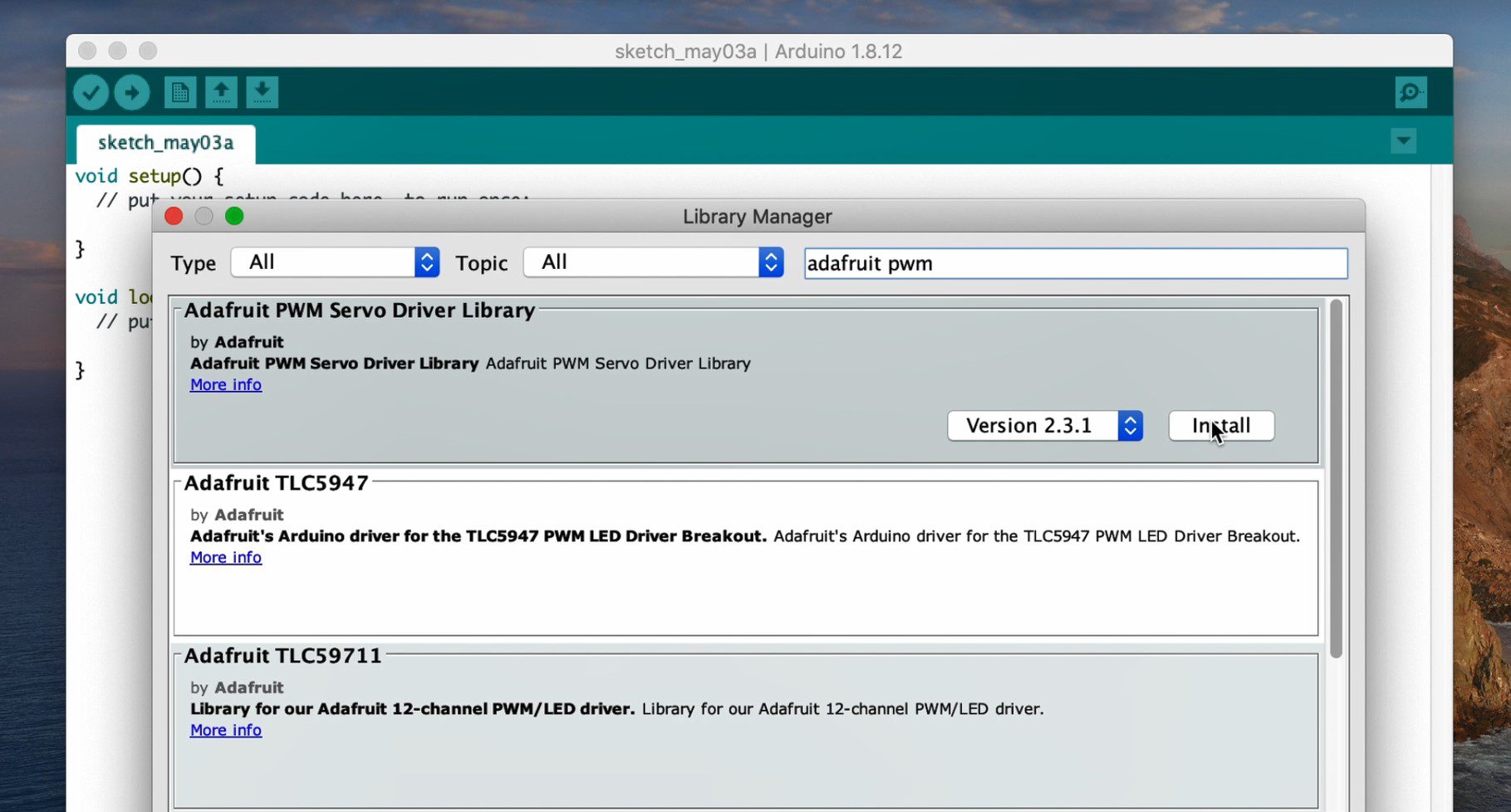
We’re going to be using the Adafruit PWM servo driver library. You can install this library easily from the Arduino IDE by going to Sketch -> Include Libraries -> Manage Libraries then searching for Adafruit PWM and clicking install.
Once the library is installed, we can write a simple program to move each of the 6 servos on each board individually.
//Michael Klements
//The DIY Life
//3 May 2020

#include <Adafruit_PWMServoDriver.h>                             //Include the PWM Driver library

Adafruit_PWMServoDriver pwm1 = Adafruit_PWMServoDriver(0x40);    //Create an object of board 1
Adafruit_PWMServoDriver pwm2 = Adafruit_PWMServoDriver(0x41);    //Create an object of board 2 (A0 Address Jumper)

int servoMin =  150;        // This is the servos minimum pulse length count (out of 4096)
int servoMax =  600;        // This is the servos maximum pulse length count (out of 4096)
int servoFrequency = 50;    // Servo update frequency, analog servos typically run at ~50 Hz

void setup()
{
  pwm1.begin();             //Start each board
  pwm2.begin();
  pwm1.setOscillatorFrequency(27000000);    //Set the PWM oscillator frequency, used for fine calibration
  pwm2.setOscillatorFrequency(27000000);
  pwm1.setPWMFreq(servoFrequency);          //Set the servo operating frequency
  pwm2.setPWMFreq(servoFrequency);
}

void loop()
{
  for (int i=0 ; i<=5 ; i++)   //Cycle through moving 6 servos on each board
  {
    for (int pulseLength = servoMin ; pulseLength <= servoMax ; pulseLength++)    //Move each servo from servoMin to servoMax
    {
      pwm1.setPWM(i, 0, pulseLength);           //Set the current PWM pulse length on board 1, servo i
      pwm2.setPWM(i, 0, pulseLength);           //Set the current PWM pulse length on board 2, servo i
      delay(1);
    }
    delay(100);
    for (int pulseLength = servoMax ; pulseLength >= servoMin ; pulseLength--)    ////Move each servo from servoMax to servoMin
    {
      pwm1.setPWM(i, 0, pulseLength);           //Set the current PWM pulse length on board 1, servo i
      pwm2.setPWM(i, 0, pulseLength);           //Set the current PWM pulse length on board 2, servo i
      delay(1);
    }
    delay(100);
  }
  delay(500);
}
Download Sketch – PCA9685Tutorial
We start by importing the Adafruit library.
We then create a new object for each of the connected boards, remembering to change the address to suite the address jumpers we’ve used.
We then set a minimum and maximum travel limits for our servos. This is quite important so that you’re not over travelling your servos which may cause them to burn out or strip the gears. We also set the servo operating frequency. Most analogue servos run at 50hz.
In the setup function, we start each board then set the oscillator frequency and the servo frequency.
In the loop function, we’ve got a loop which cycles through the six servo numbers, numbered from 0 to 5 as per the board output numbers.
We then have a loop which drives the current servos, one on each board, from their minimum position to their maximum position with a 1ms delay between movements, which is a relatively slow servo movement.
We then wait 100 milliseconds and move the same two servos from their maximum position back down to their minimum position at the same speed.
We then wait another 100 milliseconds before moving onto the next two servos.
Once all 6 servos have been moved on each board, we wait 500 milliseconds and then start again moving the first two servos and the loop continues.
Let’s upload the sketch and have a look at the servos moving.
Being able to control servos like this enables you to build more complex projects by freeing up your Arduino’s IO and reducing the processing load because these servo drivers produce their own PWM signal. These are great for building robot arms, walking robots and projects involving a lot of LEDs, such as cubes, clocks and simple games.
Let me know in the comments section below what you plan on using these drivers for.
Hi, I read your amazing article. I have one quiestion. I am a beguinner I would like to know if this circuit can handle 12v servos. If not is there any other circuit capable of handling 12v servos ?? I see the maximun voltage is 6v.
No, these drivers are designed to work with 5V servos. I’m not really too familiar with 12V servos, if their PWM signal is also required to be 12V then you’ll probably find it quite difficult to find a microcontroller-based driver circuit for them as these are almost always 3.3V or 5V.
Following up for anyone asking the same thing now: If you have a board with no MOSFET, the only component limiting the V+ voltage appears to be the large electrolytic capacitor. If you remove it or replace it with one with a higher voltage rating, you should be able to run with a V+ up to the rating of the new capacitor.
If you have a board with a tiny MOSFET next to the capacitor, it must be removed, and you can jumper (bridge with a wire or solder) the source and drain pads and leave the gate pad (the one at the edge of the board) unconnected. This will remove your polarity protection (if it was working in the first place), but your V+ will only be limited by the rating of your large capacitor.
Hi Michael.
Do the boards have to be linked in address order? That is, does the board with address 0x40 have to be the first in the chain, followed by 0x41, 0x42, etc.?
Thanks
Ron Ventura
I don’t think they do. You set the address by soldering pins on the board and then sending data to that specific address with arduino, so they should work in any order you like.
A word of warning: Many of the PCA9685 servo driver boards being sold on Amazon either do not have reverse polarity protection AT ALL (including the boards labeled “HW-170” like those in this article!), or have faulty or non-functional reverse polarity protection.
My findings, and how you can tell:
1. The boards in this article do not have any MOSFET (tiny black rectangular component with 3 pins) on the board next to the green screw terminals. V+ and the + of the green terminal appear to be directly connected. This works, but there is no reverse polarity protection.
2. Boards that have a MOSFET (the tiny 3-pin SOT23) often do not function. I’m not sure if this is because of bad MOSFETS, incorrect ones, or bad circuit design. The result is that hooking power to the green terminal does nothing. My solution is to remove the MOSFET and jumper the source and drain pads, leaving the gate (the one at the edge of the board) unconnected. This allows you to power V+ from the green terminal, but you won’t have reverse polarity protection.
3. Boards that have the larger AOD417 MOSFET presumably function fine with reverse polarity protection. I don’t have one of these as they’re harder to find, but I’m guessing changing the design to use the smaller MOSFET was a cost-cutting measure, resulting in problems on the other boards.
Perks: If you use one of the boards without polarity protection (either the one in this article, or one where you’ve removed the MOSFET and jumpered its source and drain pads), I believe the only component limiting V+ is the large electrolytic capacitor. Most boards come with one rated at 10V, meaning you can drive up to 10V servos through V+. As far as I could tell, the V+ line on these boards only runs to the capacitor and the center pins of the servo outputs. I ran the board happily at 10V.
i.e. if your board has no MOSFET or you have removed the MOSFET and jumpered as described above, you can replace the capacitor with a higher voltage one and run with V+ up to the voltage rating of your new capacitor (you can actually just remove the capacitor if your V+ power supply is steady enough and close to the board).