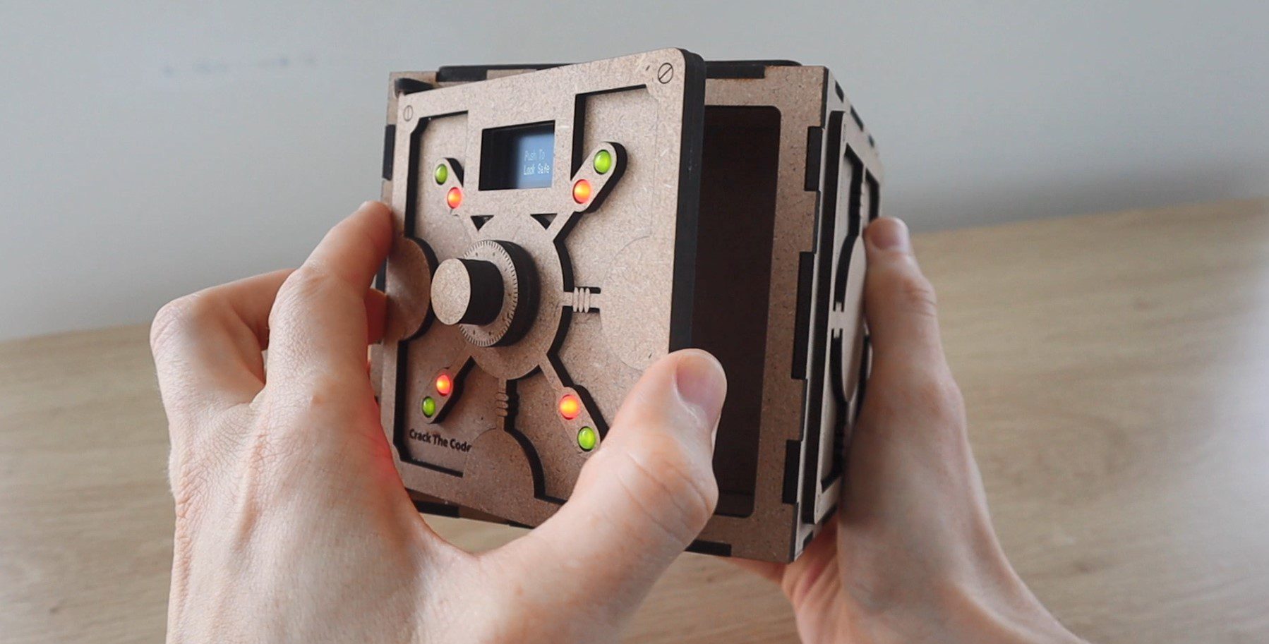
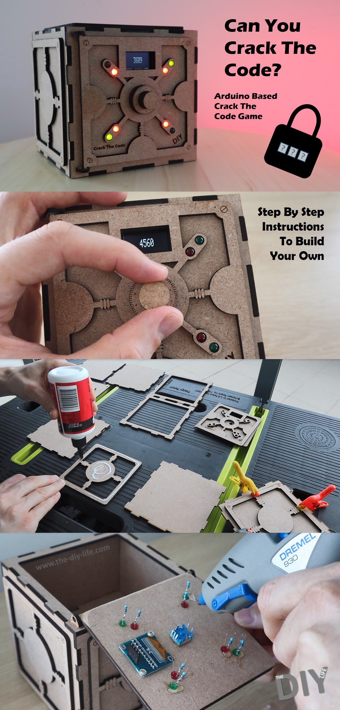
In this project, I’m going to be showing you how to build your own Arduino based crack the code game. You use a dial to guess the randomly generated code to the safe and 8 LEDs on the front of the safe then tell you how many of the digits you’ve guessed are correct and how many are in the right place as well. Using this feedback you can work your way towards cracking the code to the safe, and once you do, the game will then tell you how many attempts it took you to crack.
Here’s a video of the build. Read on for the full step by step instructions.
This project assumes you know the basics of Arduino programming, otherwise read our article on getting started with Arduino.
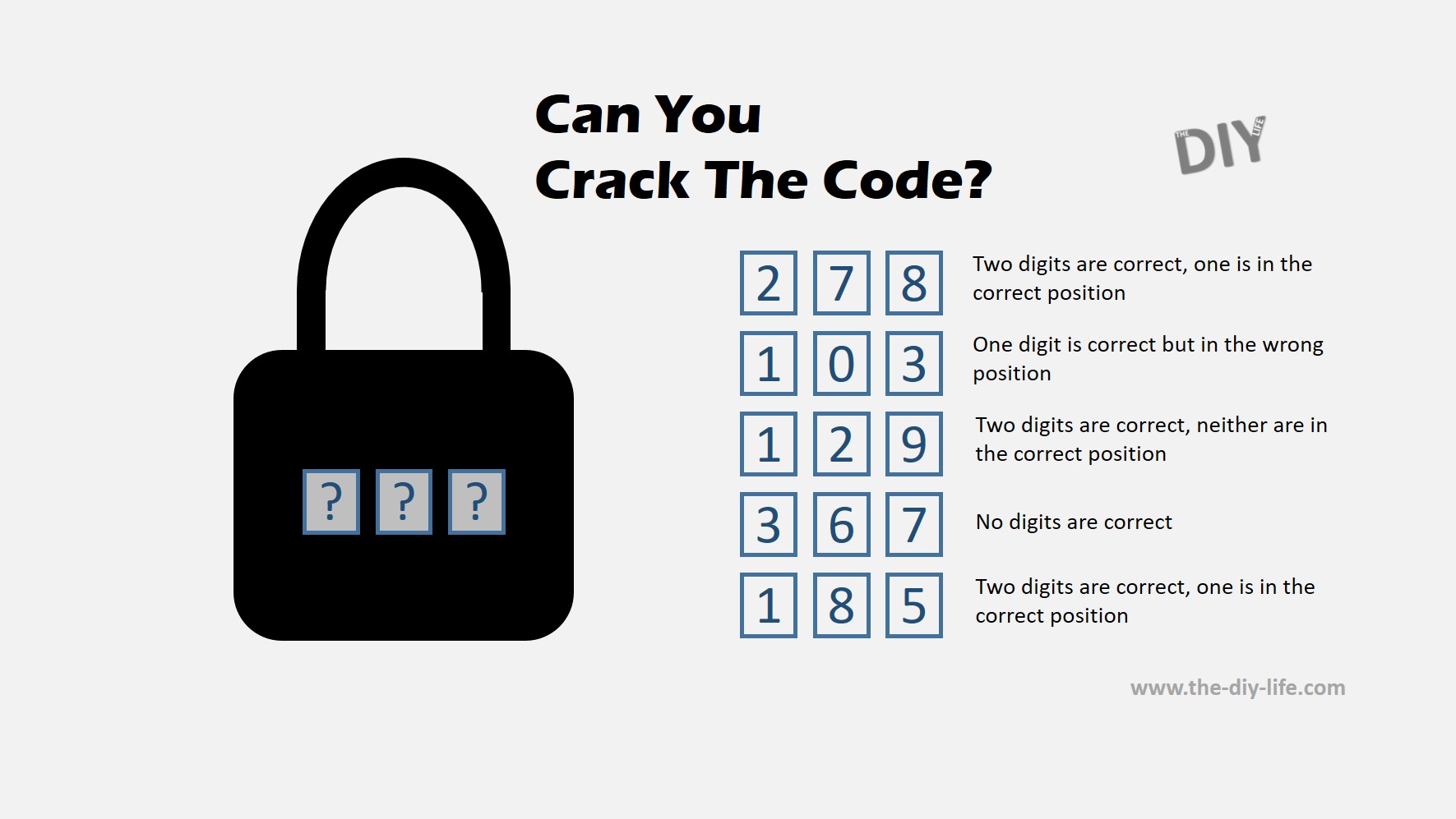
There have been a number of different forms of this game over the years, from physical pegboards in the 70s to video games, and more recently you may have seen these types of puzzles as single images on social media platforms.
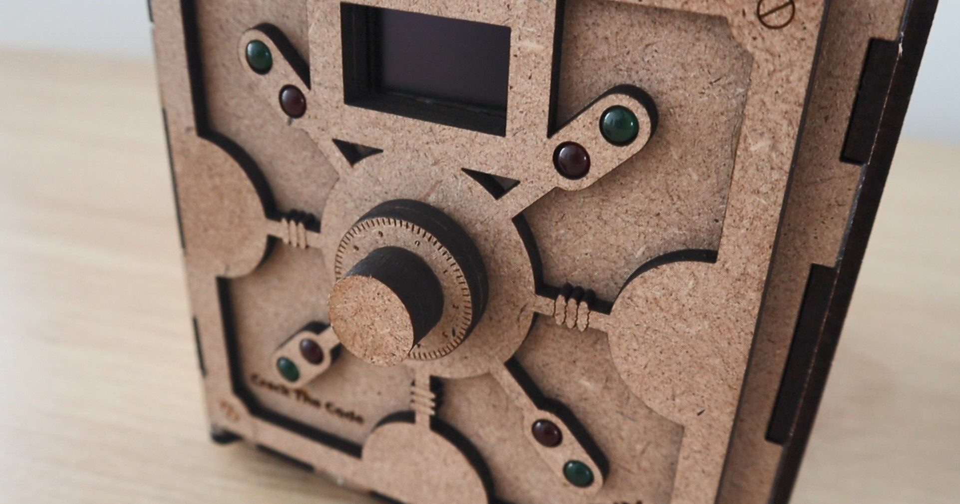
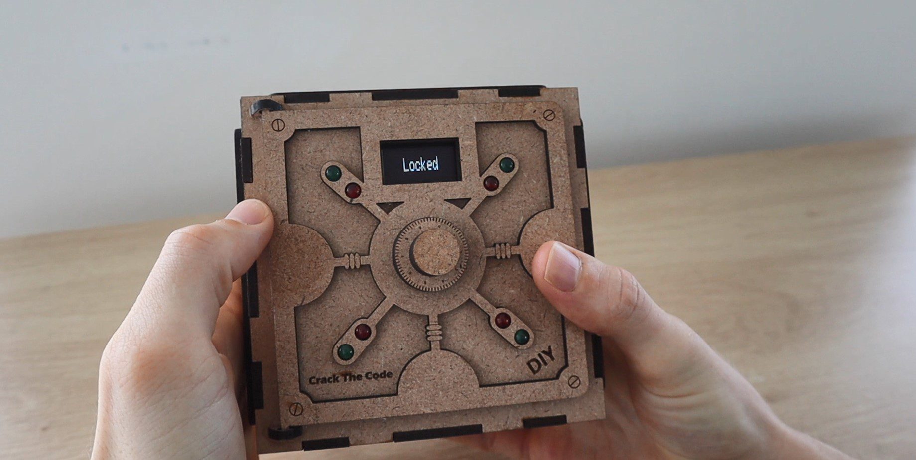
The safe is initially open, allowing you to put something into the inside compartment. You then push the dial to lock the safe using a servo on the inside of the door and a random code is generated.
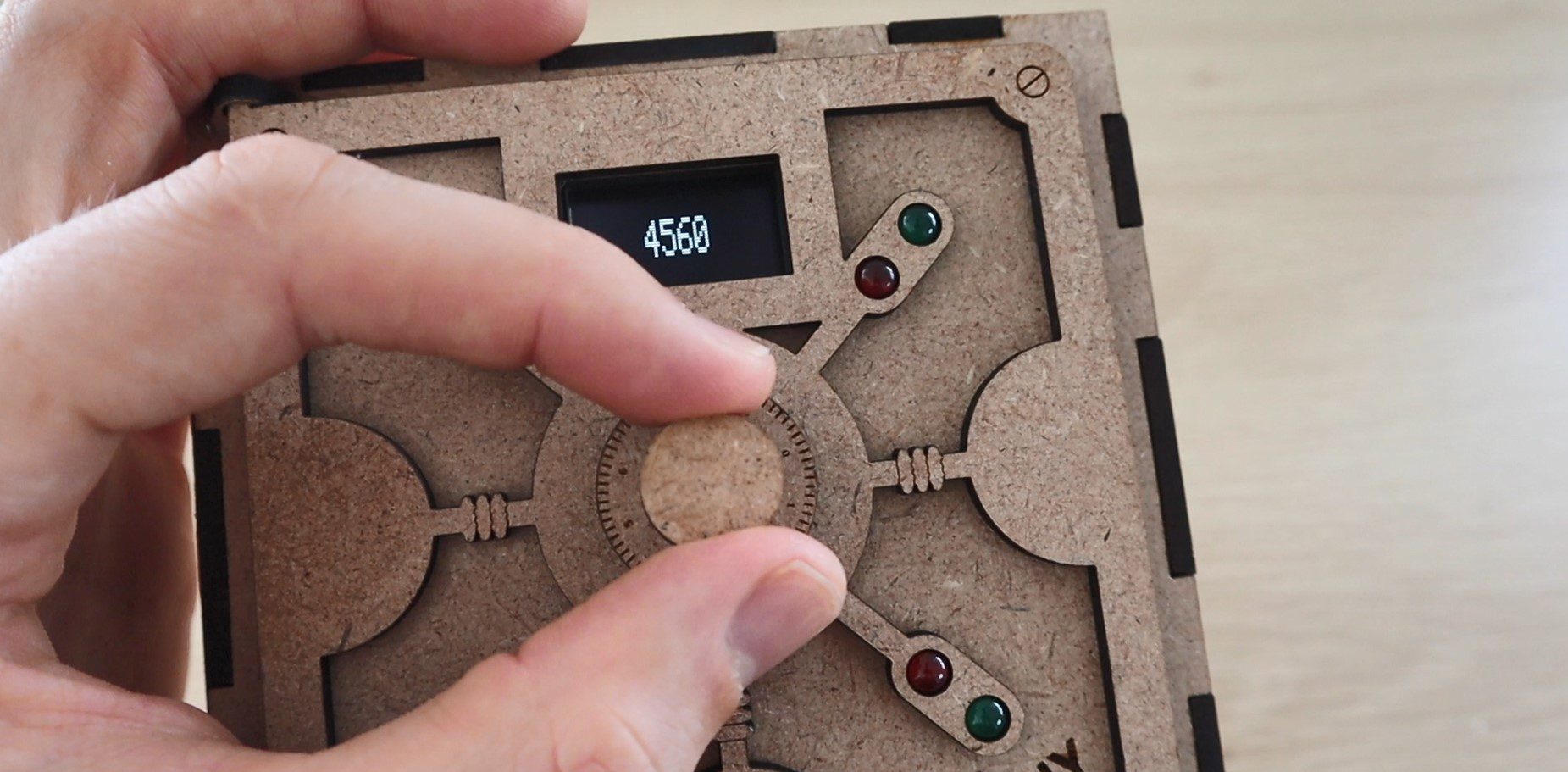
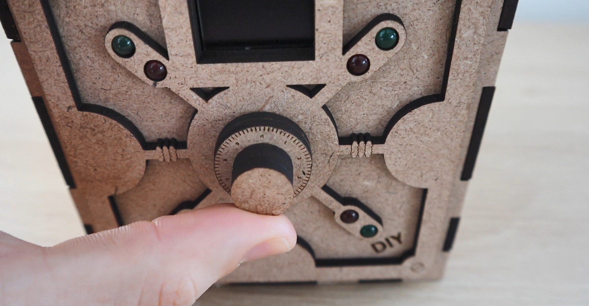
You then need to input the code by turning the dial to select the digits and pushing the dial to confirm each digit.
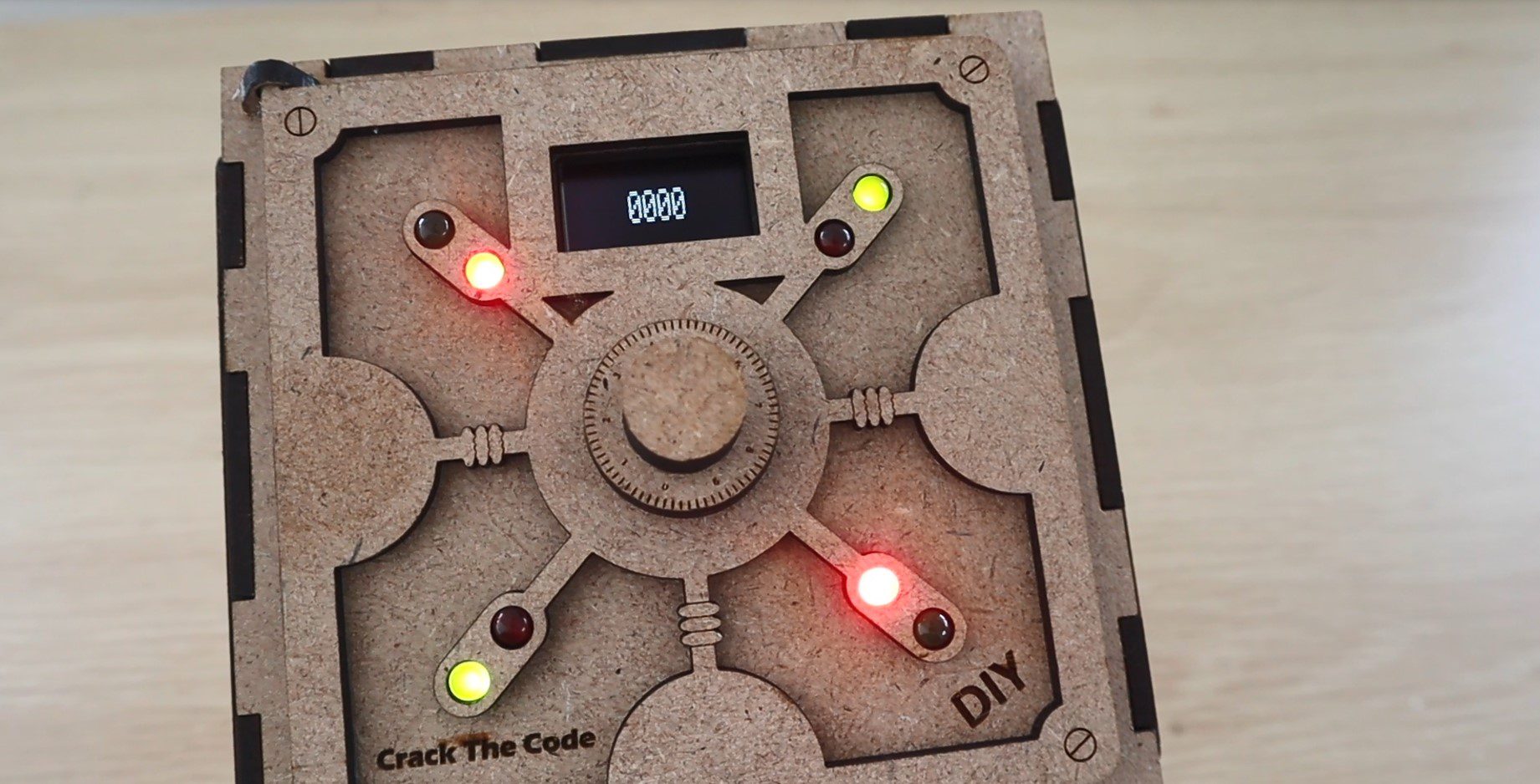
After your fourth digit is chosen, the safe displays how many of your digits are correct and how many of them are in the correct place using the red and green LEDs on the door. A red LED indicates a correct digit and a green LED indicate that it’s also in the correct place. So you’re looking to light up all four red and green LEDs in order to crack the code and open the safe.
The safe keeps track of how many guesses you’ve made in order to crack the code. It may sound complicated at first but it’s actually not that difficult. You just need to remember and build upon your previous guesses. Most of the time you should be able to crack the code in 5 to 10 guesses, depending on how lucky your initial guesses are.
What You Need To Build Your Own Crack The Code Puzzle Box
- Arduino Uno – Buy Here
- I2C OLED Display – Buy Here
- Pushbutton Encoder – Buy Here
- 4 x 5mm Red LEDs – Buy Here
- 4 x 5mm Green LEDs – Buy Here
- 8 x 220Ω Resistors – Buy Here
- Micro Servo – Buy Here
- Ribbon Cable – Buy Here
- Header Strips – Buy Here
- Power Switch – Buy Here
- 3mm MDF Sheet – Buy Here
In addition to these, you’ll also need some basic tools, a soldering iron, glue gun and some wood glue. You’ll also need to have access to a laser cutter to cut the box. If you don’t have access to one, consider using an online laser cutting service. There are quite a few options available and they’re quite affordable, they’ll even deliver to your door.
If you’re interested in a laser cutter, this is the one I’ve used for this project.
K40 Laser Cutter – Buy Here
How To Build Your Own Crack The Code Safe Box
Cutting & Assembling The Safe Box
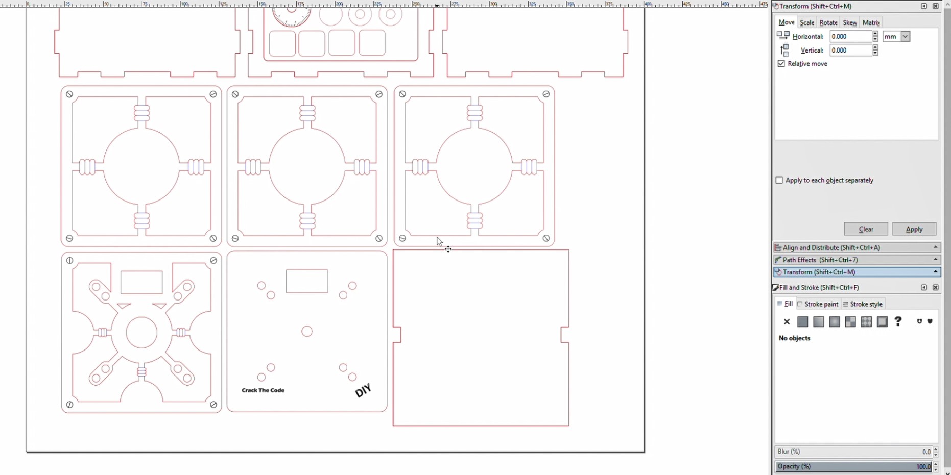
I started off by designing the safe box in Inkscape. It had to be large enough to house an Arduino Uno, have a compartment to put something into and look like a traditional safe. The pieces are designed to be cut from 3mm MDF, you could also cut the parts from 3mm acrylic or plywood. If you use a different thickness material then you’ll need to modify the edges of the box pieces so that the slots fit together.
Download The Laser Cutting File – Box Cutting Files
The download above includes svg, dxf and A3 printable pdf files to give you a couple of options for cutting or printing.
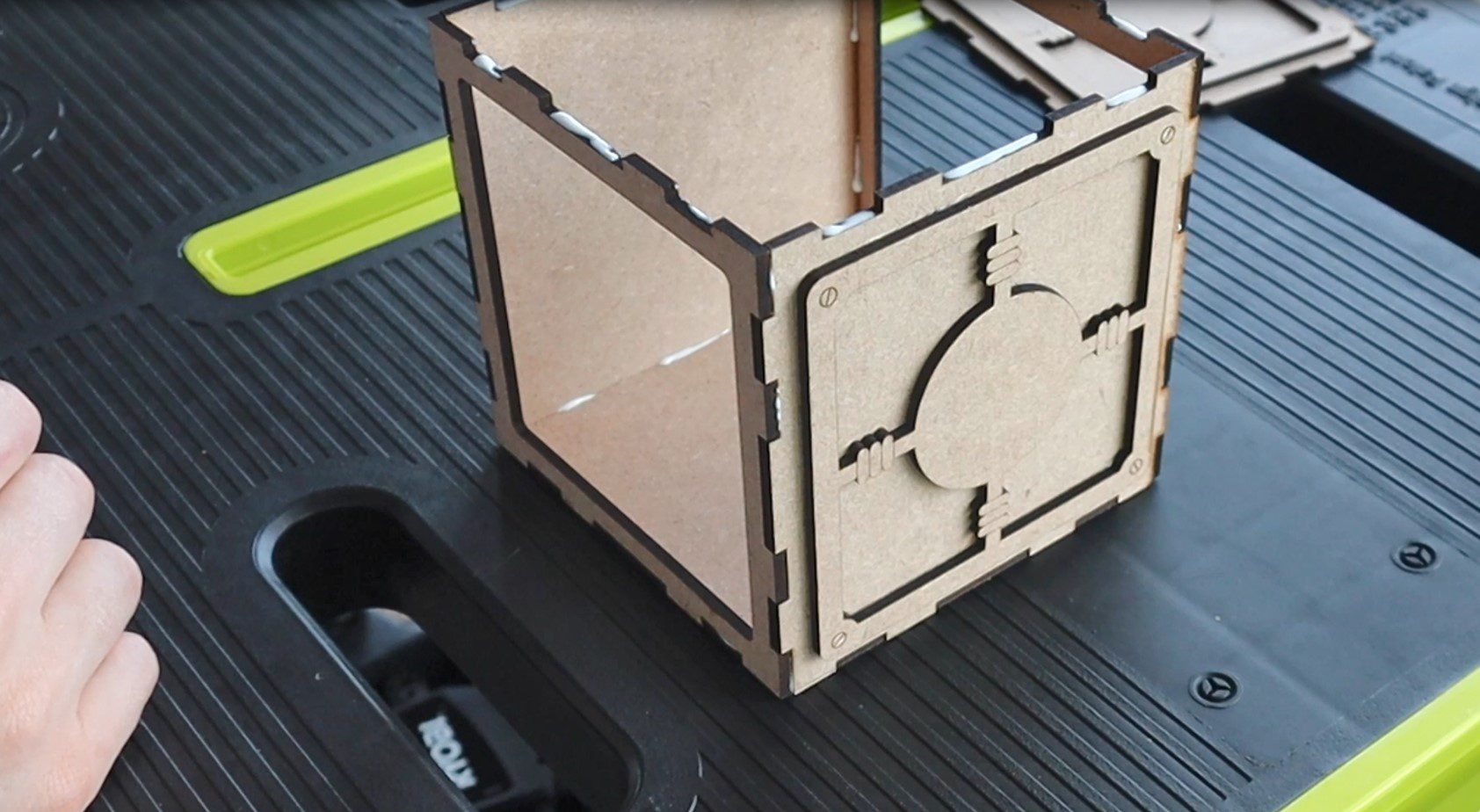
There are 6 main panels which make up the box. The front panel has a cutout in it for the door and the back has one for the Arduino and battery compartment cover. The 6 main panels are labelled in the cutting file so that you’re able to identify them.
The dial is also made up from laser-cut pieces which are then glued together.
There are three decorative panels which are stuck onto the top and two sides of the box to make it look more like a safe. There are also two panels which make up the door and a divider panel which goes into the middle of the box to separate the safe compartment from the electronics compartment.
The pieces fit onto a single piece of MDF 400 x 500mm. They can be divided up into smaller pieces, as I’ve done, if your laser cutter isn’t big enough to cut them all in one go. I cut out two sections at a time.
Let’s cut out the pieces.
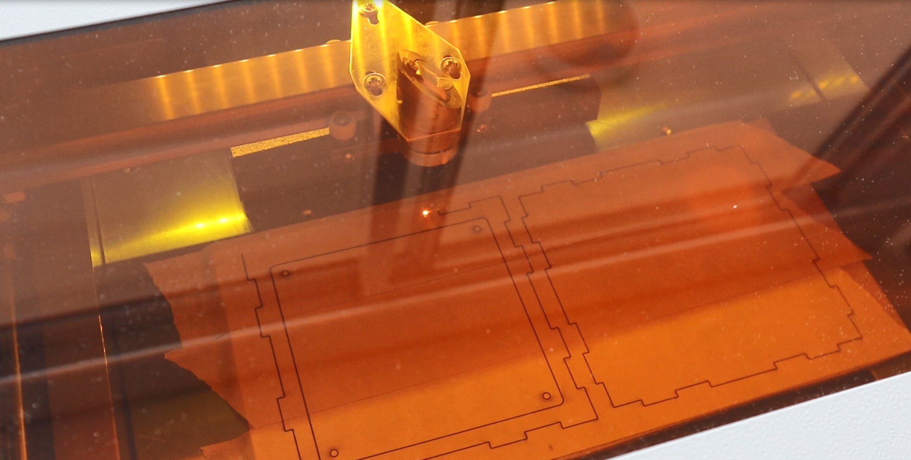
I used some masking tape to prevent the smoke from the laser from marking the wood. I had to take this off before gluing the box together, which is a little tedious but produces a much better end product.
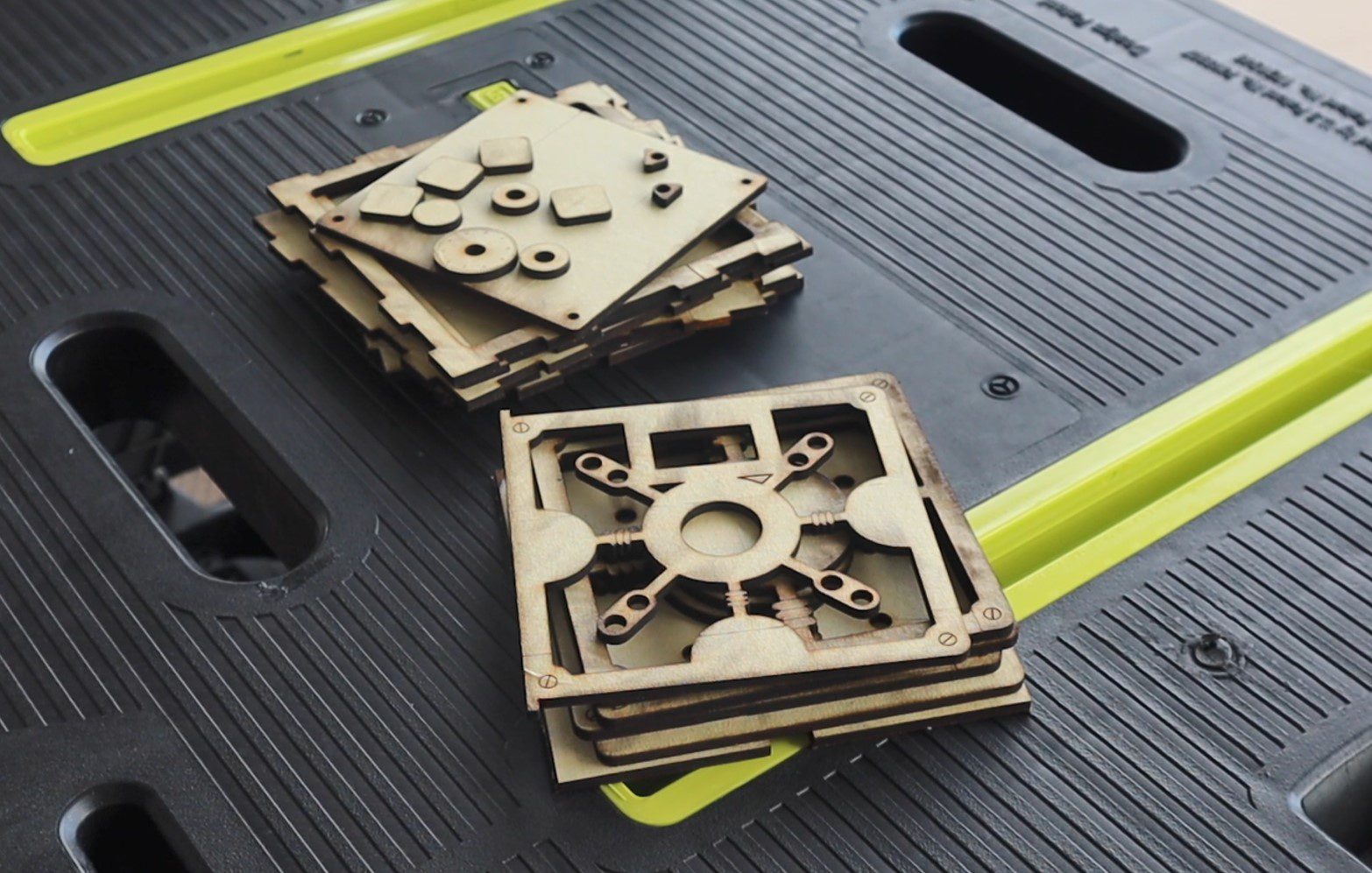
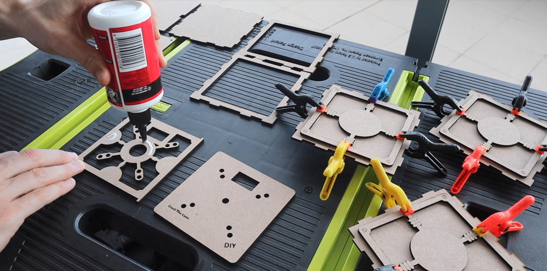
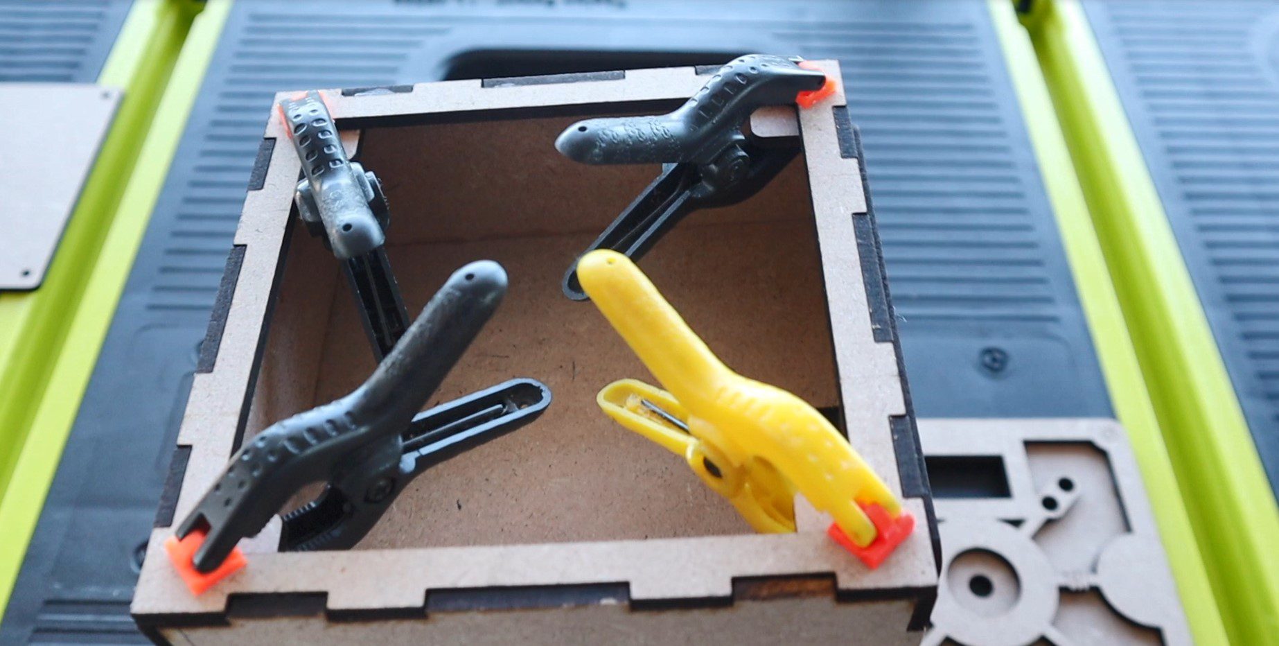
I started out gluing the decorative panels onto the top and sides first using some PVA wood glue and small plastic clamps. Make sure that you’ve got the pieces in the correct order so that you know which are which. There are three different pieces; the top and bottom are the same, the sides are the same and the front and back are the same. I’ve put text labels under each in the laser cutting file. Then glue the two door panels together.
Once the panels are dry, you can assemble the box.
Make sure the cutouts for the centre divider are on the sides. These are to run any wires from the front of the box to the back of the box where the Arduino and battery sit.
The hinges are also laser cut and just glue into place once you’ve lined up the door. Make sure that they’re parallel to the door or you’ll have difficulty opening it. Also, make sure that the door is positioned over the centre of the cutout in the box so that there are no gaps visible.
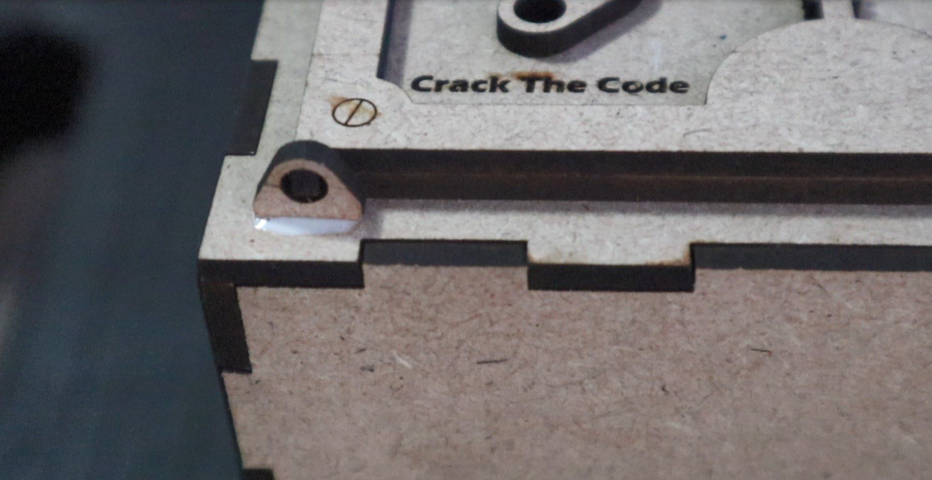
You may also need to sand a little bit off of the inside hinged edge of the door once the hinges are dry so that it doesn’t rub on the inside edge of the box cutout as it moves past.
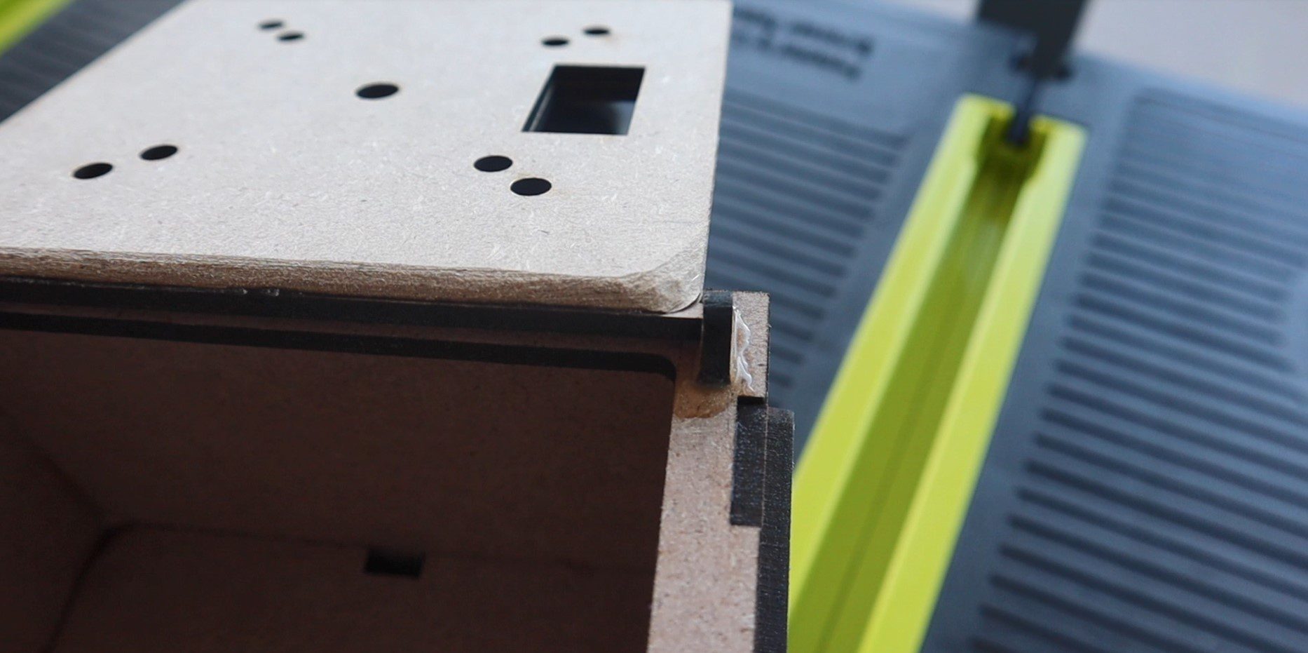
Glue the four square pieces into the corners behind the back panel to hold the screws for the back cover in place.
Then drill holes for the screws. I used a couple of spare screws I had lying around which came with the micro servos.
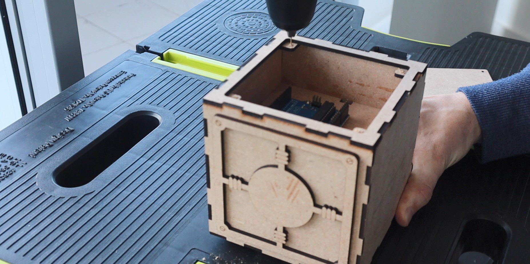
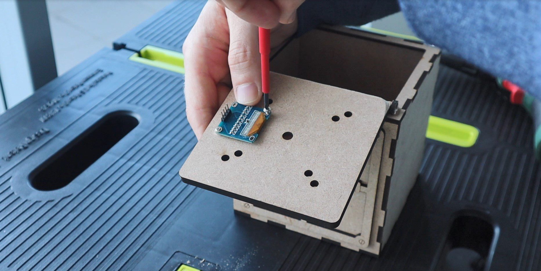
You can then mount the screen onto the door with two screws, the Arduino into the back compartment and lastly the encoder through the front door. The nut for the encoder is hidden by the recess provided by the front panel.
Connecting The Electronics
Now that the box is complete, we can start connecting the electronic components together.
Here is the schematic:
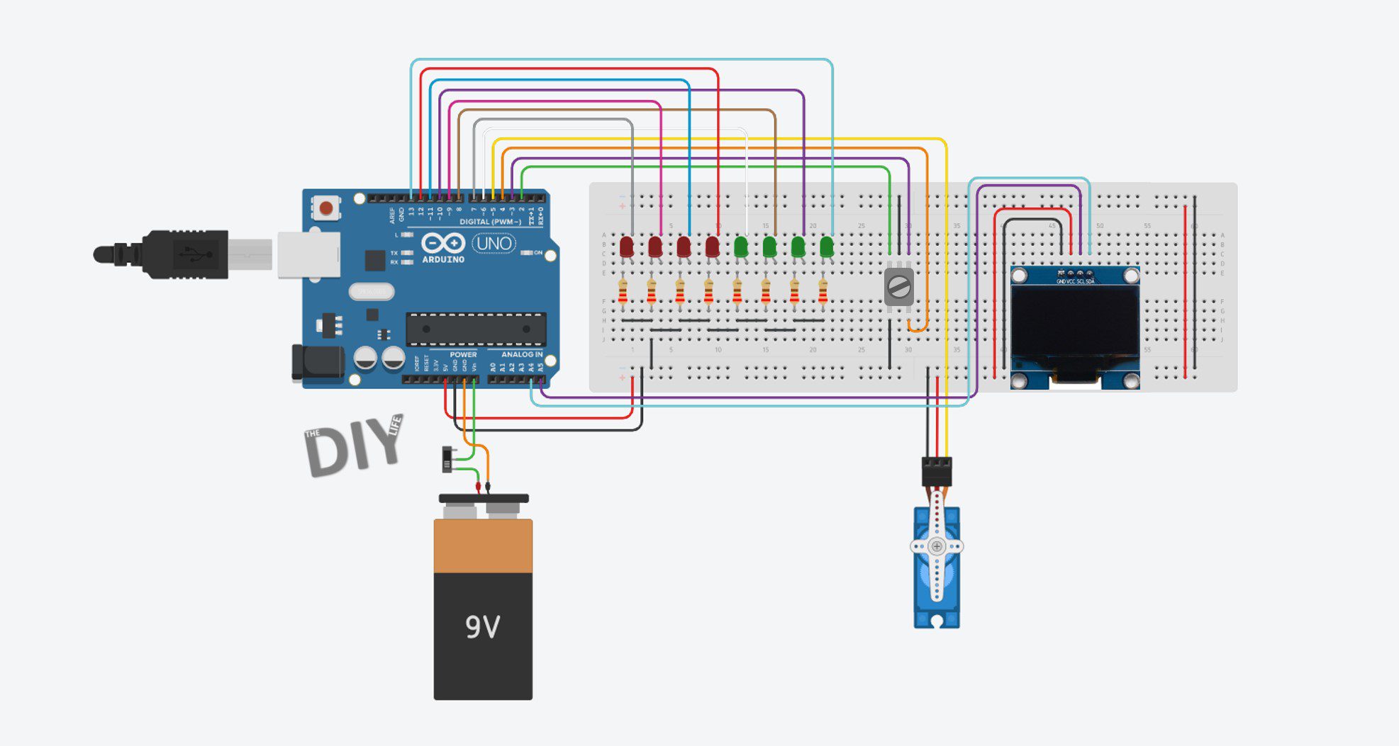
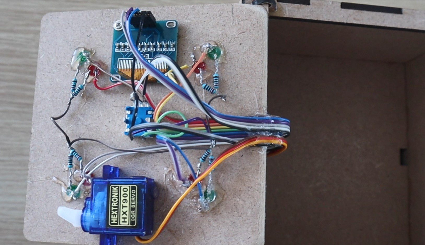
We’ve got 8 LEDs connected to the digital IO pins 6 to 13. The locking servo connected to pin 5. The encoder connected to pins 2, 3 and 4 and the OLED display connected to the Arduino’s I2C interface.
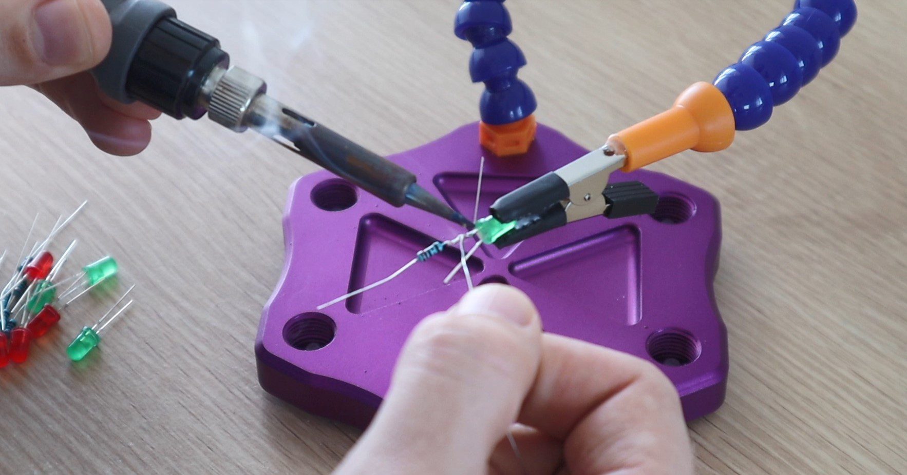
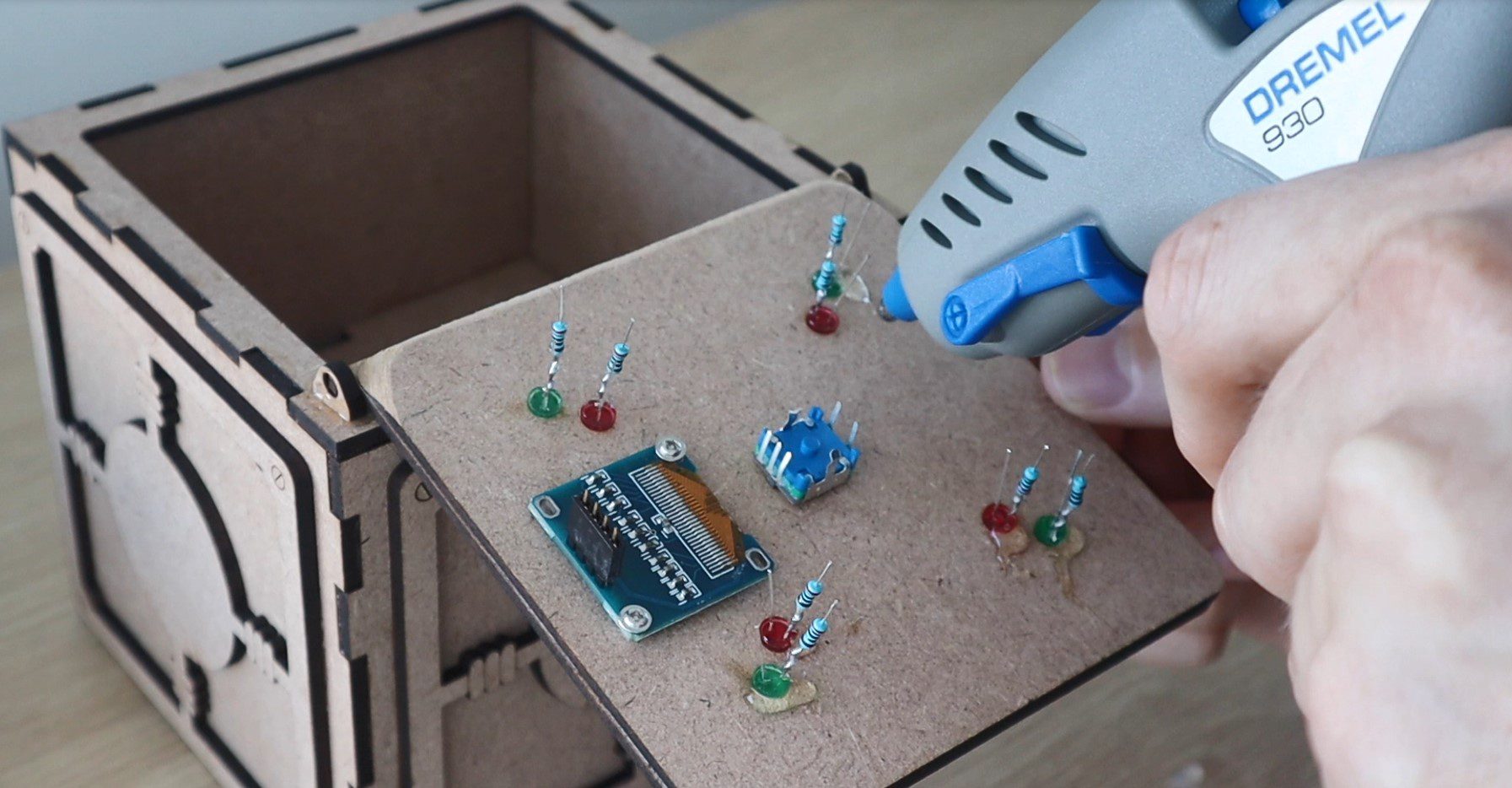
I used a 220 ohm resistor for each LED, which I soldered directly onto the cathode (negative pin) of the LED before gluing them into place with a glue gun.
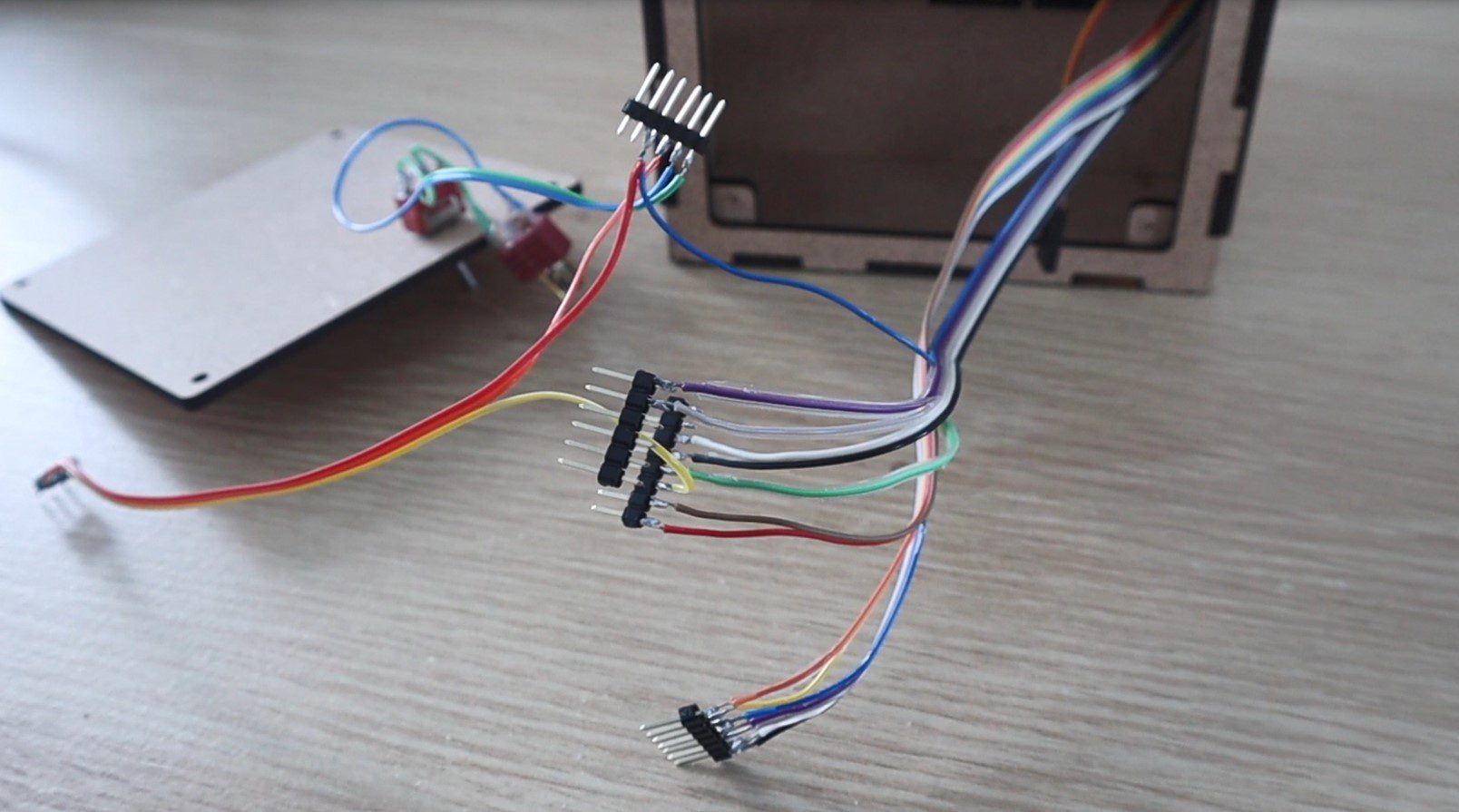
I connected the components together using coloured ribbon cable to keep the wiring neat and to help keep track of which wire needed to go to each Arduino pin.
I pushed the ribbon cables through to the back compartment and the soldered sections of header strips onto the ends to plug directly into the Arduino.
I also mounted a power switch onto the back cover and connected this to a battery plug to connect to a rechargeable battery to power the game. I used a 3 cell, 800mAh LiPo battery which I had from some RC aircraft. You could also use a 9V battery or a battery holder which houses 4 AA batteries.
Lastly, you’ll need to mount the locking servo on the door. Position it towards the edge of the door so that it passes over the lip in the box and the arm is able to push up against the inside of the lip to lock the box. This isn’t the strongest locking mechanism but it is really simple and it works for the game’s purpose.
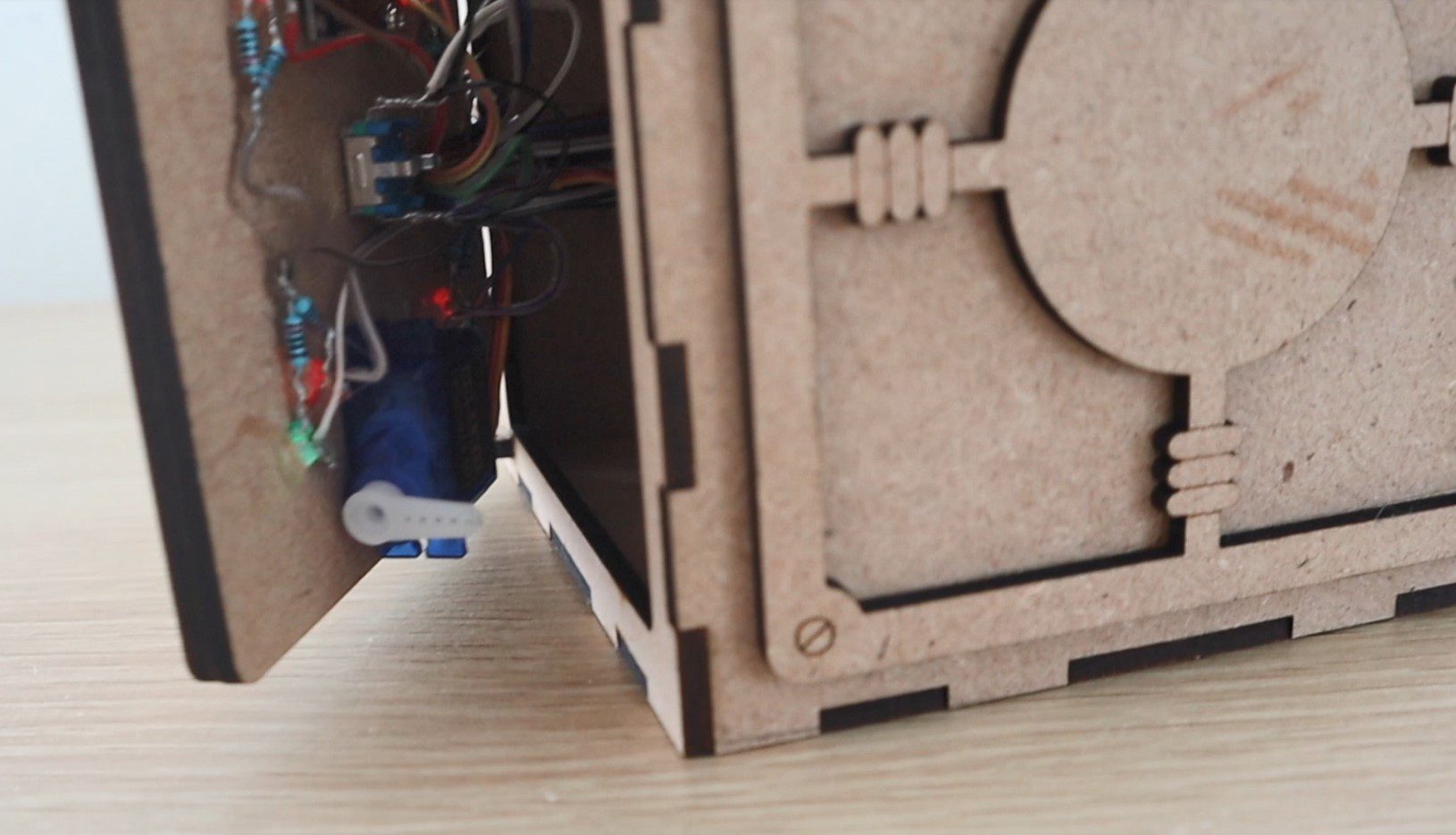
The safe box is now complete.
Coding The Game
The code for this game isn’t that complicated but is quite lengthy. I’ve tried to make the code as readable as possible by splitting it up into functions and putting in a lot of comments.
The code makes use of an interrupt routine to take the inputs from the rotary encoder, this is based on Simon Merrett’s example for a rotary encoder input which I found online. It was the most simple I could find and didn’t require any additional libraries to function.
Here is the code:
//Code Breaker
//Michael Klements
//The DIY Life
//15 May 2020
//Encoder interrupt routine adapted from Simon Merrett's example code
#include <SPI.h> //Import libraries to control the OLED display
#include <Wire.h>
#include <Adafruit_GFX.h>
#include <Adafruit_SSD1306.h>
#include <Servo.h> //Import library to control the servo
Servo lockServo; //Create a servo object for the lock servo
#define SCREEN_WIDTH 128 // OLED display width, in pixels
#define SCREEN_HEIGHT 32 // OLED display height, in pixels
#define OLED_RESET -1 // Reset pin # (or -1 if sharing Arduino reset pin)
Adafruit_SSD1306 display(SCREEN_WIDTH, SCREEN_HEIGHT, &Wire, OLED_RESET); // Declaration for an SSD1306 display connected to I2C (SDA, SCL pins)
static int pinA = 2; //Hardware interrupt digital pin 2
static int pinB = 3; //Hardware interrupt digital pin 3
volatile byte aFlag = 0; //Rising edge on pinA to signal that the encoder has arrived at a detent
volatile byte bFlag = 0; //Rising edge on pinB to signal that the encoder has arrived at a detent (opposite direction to when aFlag is set)
volatile byte encoderPos = 0; //Current value of encoder position, digit being input form 0 to 9
volatile byte prevEncoderPos = 0; //To track whether the encoder has been turned and the display needs to update
volatile byte reading = 0; //Stores direct value from interrupt pin
const byte buttonPin = 4; //Pin number for encoder push button
byte oldButtonState = HIGH; //First button state is open because of pull-up resistor
const unsigned long debounceTime = 10; //Debounce delay time
unsigned long buttonPressTime; //Time button has been pressed for debounce
byte correctNumLEDs[4] = {9,12,7,11}; //Pin numbers for correct number LEDs (Indicate a correct digit)
byte correctPlaceLEDs[4] = {6,10,8,13}; //Pin numbers for correct place LEDs (Indicate a correct digit in the correct place)
byte code[4] = {0,0,0,0}; //Create an array to store the code digits
byte codeGuess[4] = {0,0,0,0}; //Create an array to store the guessed code digits
byte guessingDigit = 0; //Tracks the current digit being guessed
byte numGuesses = 0; //Tracks how many guesses it takes to crack the code
boolean correctGuess = true; //Variable to check whether the code has been guessed correctly, true initially to generate a new code on startup
void setup()
{
Serial.begin(9600); //Starts the Serial monitor for debugging
if(!display.begin(SSD1306_SWITCHCAPVCC, 0x3C)) //Connect to the OLED display
{
Serial.println(F("SSD1306 allocation failed")); //If connection fails
for(;;); //Don't proceed, loop forever
}
display.clearDisplay(); //Clear display
lockServo.attach(5); //Assign the lock servo to pin 5
for(int i=0 ; i<=3 ; i++) //Define pin modes for the LEDs
{
pinMode(correctNumLEDs[i], OUTPUT);
pinMode(correctPlaceLEDs[i], OUTPUT);
}
pinMode(pinA, INPUT_PULLUP); //Set pinA as an input, pulled HIGH to the logic voltage
pinMode(pinB, INPUT_PULLUP); //Set pinB as an input, pulled HIGH to the logic voltage
attachInterrupt(0,PinA,RISING); //Set an interrupt on PinA
attachInterrupt(1,PinB,RISING); //Set an interrupt on PinB
pinMode (buttonPin, INPUT_PULLUP); //Set the encoder button as an input, pulled HIGH to the logic voltage
randomSeed(analogRead(0)); //Randomly choose a starting point for the random function, otherwise code pattern is predictable
display.setTextColor(SSD1306_WHITE); //Set the text colour to white
startupAni(); //Display the startup animation
}
void loop()
{
if(correctGuess) //Code between games to reset if the guess is correct, initially true to open safe and then generate new code
{
lockServo.write(140); //Unlock the safe
delay(300);
updateLEDs (0,4); //Flashing LED sequence
delay(300);
updateLEDs (4,0);
delay(300);
updateLEDs (0,4);
delay(300);
updateLEDs (4,0);
delay(300);
updateLEDs (4,4); //Turn all LEDs on
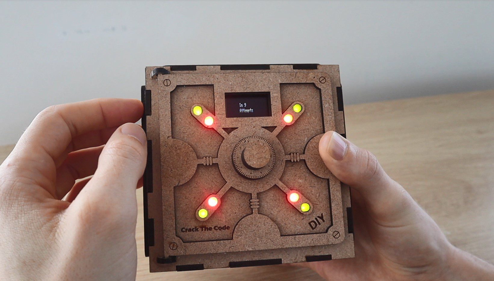
if(numGuesses >= 1) //Check that its not the start of the game
{
display.clearDisplay(); //Clear the display
display.setTextSize(1); //Set the display text size to small
display.setCursor(35,10); //Set the display cursor position
display.print(F("In ")); //Set the display text
display.print(numGuesses); //Set the display text
display.setCursor(35,20); //Set the display cursor position
display.print(F("Attempts")); //Set the display text
display.display(); //Output the display text
delay(5000);
}
display.clearDisplay(); //Clear the display
display.setTextSize(1); //Set the display text size to small
display.setCursor(35,10); //Set the display cursor position
display.print(F("Push To")); //Set the display text
display.setCursor(35,20); //Set the display cursor position
display.print(F("Lock Safe")); //Set the display text
display.display(); //Output the display text
display.setTextSize(2); //Set the display text size back to large
boolean lock = false; //Safe is initially not locked
boolean pressed = false; //Keeps track of button press
while(!lock) //While button is not pressed, wait for it to be pressed
{
byte buttonState = digitalRead (buttonPin);
if (buttonState != oldButtonState)
{
if (millis () - buttonPressTime >= debounceTime) //Debounce button
{
buttonPressTime = millis (); //Time when button is pressed
oldButtonState = buttonState; //Remember button state
if (buttonState == LOW)
{
pressed = true; //Records button has been pressed
}
else
{
if (pressed == true) //Makes sure that button is pressed and then released before continuing in the code
{
lockServo.write(45); //Lock the safe
display.clearDisplay(); //Clear the display
display.setCursor(30,10); //Set the display cursor position
display.print(F("Locked")); //Set the display text
display.display(); //Output the display text
lock = true;
}
}
}
}
}
generateNewCode(); //Calls function to generate a new random code
updateLEDs (0,0);
correctGuess = false; //The code guess is initially set to incorrect
numGuesses = 0; //Reset the number of guesses counter
}
inputCodeGuess(); //Calls function to allow the user to input a guess
numGuesses++; //Increment the guess counter
checkCodeGuess(); //Calls function to check the input guess
encoderPos = 0; //Reset the encoder position
guessingDigit = 0; //Reset the digit being guessed
codeGuess[0] = 0; //Reset the first digit of the code
updateDisplayCode(); //Update the displayed code
}
void updateDisplayCode() //Function to update the display with the input code
{
String temp = ""; //Temporary variable to concatenate the code string
if(!correctGuess) //If the guess is not correct then update the display
{
for (int i=0 ; i<guessingDigit ; i++) //Loops through the four digits to display them
{
temp = temp + codeGuess[i];
}
temp = temp + encoderPos;
for (int i=guessingDigit+1 ; i<=3 ; i++)
{
temp = temp + "0";
}
Serial.println(temp); //Output to Serial monitor for debugging
display.setTextSize(2); //Set the display text size
display.clearDisplay(); //Clear the display
display.setCursor(40,10); //Set the display cursor position
display.println(temp); //Set the display text
display.display(); //Update the display
}
}
void generateNewCode() //Function to generate a new random code
{
Serial.print("Code: ");
for (int i=0 ; i<= 3 ; i++) //Loops through the four digits and assigns a random number to each
{
code[i] = random(0,9); //Generate a random number for each digit
Serial.print(code[i]); //Display the code on Serial monitor for debugging
}
Serial.println();
}
void inputCodeGuess() //Function to allow the user to input a guess
{
for(int i=0 ; i<=3 ; i++) //User must guess all four digits
{
guessingDigit = i;
boolean confirmed = false; //Both used to confirm button push to assign a digit to the guess code
boolean pressed = false;
encoderPos = 0; //Encoder starts from 0 for each digit
while(!confirmed) //While the user has not confirmed the digit input
{
byte buttonState = digitalRead (buttonPin);
if (buttonState != oldButtonState)
{
if (millis () - buttonPressTime >= debounceTime) //Debounce button
{
buttonPressTime = millis (); //Time when button was pushed
oldButtonState = buttonState; //Remember button state for next time
if (buttonState == LOW)
{
codeGuess[i] = encoderPos; //If the button is pressed, accept the current digit into the guessed code
pressed = true;
}
else
{
if (pressed == true) //Confirm the input once the button is released again
{
updateDisplayCode(); //Update the code being displayed
confirmed = true;
}
}
}
}
if(encoderPos!=prevEncoderPos) //Update the displayed code if the encoder position has changed
{
updateDisplayCode();
prevEncoderPos=encoderPos;
}
}
}
}
void checkCodeGuess() //Function to check the users guess against the generated code
{
int correctNum = 0; //Variable for the number of correct digits in the wrong place
int correctPlace = 0; //Variable for the number of correct digits in the correct place
int usedDigits[4] = {0,0,0,0}; //Mark off digits which have been already identified in the wrong place, avoids counting repeated digits twice
for (int i=0 ; i<= 3 ; i++) //Loop through the four digits in the guessed code
{
for (int j=0 ; j<=3 ; j++) //Loop through the four digits in the generated code
{
if (codeGuess[i]==code[j]) //If a number is found to match
{
if(usedDigits[j]!=1) //Check that it hasn't been previously identified
{
correctNum++; //Increment the correct digits in the wrong place counter
usedDigits[j] = 1; //Mark off the digit as been identified
break; //Stop looking once the digit is found
}
}
}
}
for (int i=0 ; i<= 3 ; i++) //Compares the guess digits to the code digits for correct digits in correct place
{
if (codeGuess[i]==code[i]) //If a correct digit in the correct place is found
correctPlace++; //Increment the correct place counter
}
updateLEDs(correctNum, correctPlace); //Calls a function to update the LEDs to reflect the guess
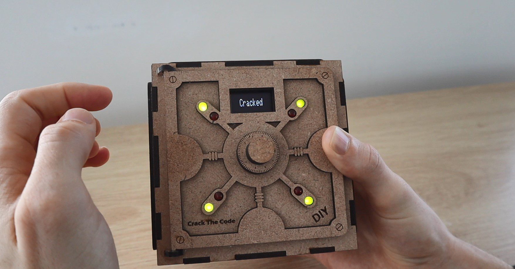
if(correctPlace==4) //If all 4 digits are correct then the code has been cracked
{
display.clearDisplay(); //Clear the display
display.setCursor(20,10); //Set the display cursor position
display.print(F("Cracked")); //Set the display text
display.display(); //Output the display text
correctGuess = true;
}
else
correctGuess = false;
}
void updateLEDs (int corNum, int corPla) //Function to update the LEDs to reflect the guess
{
for(int i=0 ; i<=3 ; i++) //First turn all LEDs off
{
digitalWrite(correctNumLEDs[i], LOW);
digitalWrite(correctPlaceLEDs[i], LOW);
}
for(int j=0 ; j<=corNum-1 ; j++) //Turn on the number of correct digits in wrong place LEDs
{
digitalWrite(correctNumLEDs[j], HIGH);
}
for(int k=0 ; k<=corPla-1 ; k++) //Turn on the number of correct digits in the correct place LEDs
{
digitalWrite(correctPlaceLEDs[k], HIGH);
}
}
void startupAni ()
{
display.setTextSize(2); //Set the display text size
display.setCursor(35,10); //Set the display cursor position
display.println(F("Crack")); //Set the display text
display.display(); //Output the display text
delay(500);
display.clearDisplay(); //Clear the display
display.setCursor(45,10);
display.println(F("The"));
display.display();
delay(500);
display.clearDisplay();
display.setCursor(40,10);
display.println(F("Code"));
display.display();
delay(500);
display.clearDisplay();
}
void PinA() //Rotary encoder interrupt service routine for one encoder pin
{
cli(); //Stop interrupts happening before we read pin values
reading = PIND & 0xC; //Read all eight pin values then strip away all but pinA and pinB's values
if(reading == B00001100 && aFlag) //Check that we have both pins at detent (HIGH) and that we are expecting detent on this pin's rising edge
{
if(encoderPos>0)
encoderPos --; //Decrement the encoder's position count
else
encoderPos = 9; //Go back to 9 after 0
bFlag = 0; //Reset flags for the next turn
aFlag = 0; //Reset flags for the next turn
}
else if (reading == B00000100) //Signal that we're expecting pinB to signal the transition to detent from free rotation
bFlag = 1;
sei(); //Restart interrupts
}
void PinB() //Rotary encoder interrupt service routine for the other encoder pin
{
cli(); //Stop interrupts happening before we read pin values
reading = PIND & 0xC; //Read all eight pin values then strip away all but pinA and pinB's values
if (reading == B00001100 && bFlag) //Check that we have both pins at detent (HIGH) and that we are expecting detent on this pin's rising edge
{
if(encoderPos<9)
encoderPos ++; //Increment the encoder's position count
else
encoderPos = 0; //Go back to 0 after 9
bFlag = 0; //Reset flags for the next turn
aFlag = 0; //Reset flags for the next turn
}
else if (reading == B00001000) //Signal that we're expecting pinA to signal the transition to detent from free rotation
aFlag = 1;
sei(); //Restart interrupts
}
Download The Code – CrackTheCode
We start by importing libraries to control the OLED display and the servo. The libraries are used to drive the OLED display, you can find more information on driving these OLED displays on Adafruit’s page on using I2C OLED displays.
We then set the parameters for the display and create all of our variables.
I’ve separated the variables into sections and given each a comment to identify their function. There are quite a few variables dedicated to tracking the encoder turns as these are done through rising edge interrupts on pins 2 and 3. The LED pins are assigned through to arrays which make updating them a bit easier. There are two code arrays created, on to store the randomly generated code and one to store the user’s current guess. There are also a few variables to track whether the uses code is correct, which digit is currently being guessed and how many guesses the user has made so far.
In the setup function, we start the display, which won’t progress unless the connection to the display is successful. Then attach the servo, set the LED and encoder IO pin modes. We then make use of the randomSeed function which reads in from an open analog input in order to randomise the starting point for the random function. If we don’t do this then the randomly generated codes will follow a predictable pattern which we’ll soon be able to identify. Lastly, we display the Crack The Code text animation on the display.
The loop function flashes the LEDs and displays the message “push to lock safe” which then waits until the user pushes the dial to start the game. The same code is run at the end of a game which then displays the number of attempts and waits for a dial press to start a new game.
There is some debouncing code on the encoder pushbutton and once pushed, the servo locks the safe and a random code is generated. The code then calls a function to ask the user to input their guess and then another to check the guess, this is repeated until the user guesses the code correctly. After each code guess, we increment the number of guesses counter and reset the input code so that the user can select a code from 0000 again. You could also change this to carry on from the previous code again if you’d prefer.
There is a function to update the code being displayed, which is called every time the encoder is turned and the displayed code needs to change. This just loops through the code guess array and displays the four digits.
The function to generate a new code simply assigns a random digit to each of the four elements in the code array.
The function to input a code guess allows the user to select a digit using the encoder and then confirm each digit input by pushing the encoder down. The displayed code is updated after each button push and any time that the encoder position has been changed. So the encoder updates the position variable using the interrupt function and this portion of the code checks if the variable has been changed and then updates the code accordingly. The interrupt doesn’t directly drive any portions of the code, it only updates the encoder position variable.
The check code guess function then looks through the guessed code and decides how many digits are correct and how many are in the correct place. There is more code to the logic behind the digits in the incorrect place so that duplicates in the user’s input and in the generated code are managed. So if the user guesses 5555 and the code contains one 5 then only one of the red LEDs will light up. The same goes for the user guessing a single 5 in their code while the generated code contains two 5s, only one red LED will light up. The correct digit in the correct place check is a simple comparison of the digits in each position of the two arrays.
The update LEDs function switches the correct number of red and green LEDs on based on the output from the check code guess function.
The startup ani function displays the three-word “Crack The Code” animation on startup.
Lastly, two interrupt functions manage the input from the encoder, one incrementing the digit upwards when turned clockwise and one downwards when turned anticlockwise. These are both rising edge interrupts available on pins 2 and 3 of an Arduino Uno. These could also be set as falling edge or low level interrupts. You can read more on the Arduino’s available interrupts if they interest you.
Now let’s upload the code and try it out.
Edit: Modify Code To Start With Locked Box
I’ve had quite a few people ask about how to start the box off locked rather than with the current push to start the game and lock the box. This is quite easy to change, you just need to modify three lines:
Add lockServo.write(45) into the setup function (at the end) to lock the safe when the box is turned on.
Move line 73 – lockServo.write(140) into the if statement below it (at the beginning). The statement starting on line 84, so insert it into line 86. This will then only unlock the box again once the guess is correct.
Change the displayed text in line 101 to read display.print(F(“Start”)). As the box will already be locked on startup.
This will then start the box off locked. You’ll still need to press the encoder to start the game but this won’t do anything to the lock in the first round as it will already be locked. In subsequent games, starting the game will lock the box again.
Playing The Game and Trying To Crack The Code
The guessed code is input using the dial to increment the digit and a push on the dial to go to the next digit or to confirm the code once all four digits are selected.
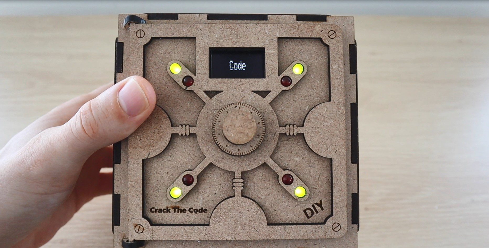
The LEDs on the front then light up to tell us what was correct in our guess. The red LEDs indicate that you’ve got a correct digit but not necessarily in the correct place and the green LEDs indicate that the digit is also in the correct place. The position or order of the LEDs is meaningless, they don’t give you any further information. Remember that you’ll need to be careful with double digits as the LEDs don’t light up multiples times for repeated digits unless you’ve repeated the digit in your guessed code.
The safe is initially unlocked, allowing you to put something inside it.
We then push the dial to lock the safe and generate a new code. You then have to try and figure out the code in order to open the safe again.
Once you’ve cracked the code, the box will unlock and display the number of attempts it took you to unlock it.
The easiest way to see how the game is played is to watch the video at the beginning which has two demonstrations near the end.
Enjoy building your own crack the code safe box. Let me know how it goes for you or what changes you’ve made to it in the comments section.
Community Builds
Asaf Matan has made some fantastic modifications to the puzzle box to make the storage area a little larger, separate the electronics and to run on an ESP32 instead of an Arduino. Take a look at his blog post for the code and some additional build images:


Share This Guide
Dear Michael
thanks for conceiving and sharing the crack-the-code-game and the vault.
I build it together with my son, and he liked it — well, actually, I did most of the building part and he did most of the cracking part 🙂
We did some changes to the original design though:
a) We used an ESP32 instead of an arduino and adapted the software. If you wish, I can share with you, so you can make it available for others.
b) The hinges glued to the frame are too weak and frequently become loose. I strengthened them using a lug. This however does not lock too well. Here I would suggest to change the geometry of the hinges, make them longer and add 2 rectangular openings to the front panel of the vault. The extended hinges could then be stuck through the holes. If each of the hinges have an additional hole it would be possible to fix them from the inside of the vault with an additional (wooden) pin.
c) My son want to have an integrated charger for the battery. So we added one:
https://www.ebay.de/itm/5V-18650-Lithium-Battery-Boost-UPS-Uninterrupted-Protection-Charging-Power-Board/173875727531
To mount it, we brought some leftover plywood in form, glued it to the back panel and mounted the UPS on it using small screws.
d) I widened one opening on the separator panel in the inside of the vault, so that all cables from coming from the door fit easily through and can slide a little forth and back, if the door is opened or closed
e) From some left over plywood I build a strain relieve for the cables connected to some device on the front door.
If you sent me your email address, I can sent you photos in return — that makes it maybe easier to understand the changes.
Best regards
Tilman
Hi Tilman,
Thanks for the great feedback. Yes I’d be happy to share your ESP32 code, and also any pictures if you’ve got available? You can send them to admin(at)the-diy-life(dot)com.
I also like your suggestions on the hinges, they are a bit fragile as currently designed.
Well done on the build!
Dear, I also wanted to cut out the parts with the laser. My laser can handle a maximum of A4 format. As a beginner, I cannot transfer your A3 format to an A4 format. May I ask you to do that for me please. I am 82 years old and it is sometimes a bit more difficult for me. Thanks in advance. Kind regards, Guido.
Hi, great article. Looking forward to build one… and also for version with integrated charger 🙂
Awesome, good luck!
Hello Michael,
Thanks a lot for sharing this project it is amazing. The first time I saw it I knew I had to build it. Since I don’t have access to a laser cutter I decided to port it to a 3d printer. So I took the svg files and manage to convert them into stl files so I can print them. I redesigned the button to my liking. Also, instead of using an Arduino Uno, I went for the Nano and because of that I was able to fit all the electronics on the front door, only 2 wires for the battery going to the back compartment.
Thanks again for sharing.
Best regards,
Jean
Hi Jean,
Thats great! Congratulations on your build and thanks for the feedback! Would you be happy to share some pictures of your build? I’d like to include a photo or two of a 3D printed one on the post as well.
Thank you!
Hello Michael,
I tried to post a picture on your blog but was not able so I posted a “Make” on Thingiverse with a picture of the safe.
https://www.thingiverse.com/make:883722
Regards,
Jean
Awesome, it looks great!
Hi Jean
Are those .stl files available? I just finished the electronics and it is a great puzzle.
Hi Bill,
Just added the stl files to the Thingiverse page.
Hello,
I am a beginner in Arduino coding and I want to do this project. It is really cool!
I am using an Arduino mega. I have changed the pins for the OLED pins accordingly. However, I am facing a problem with the rotary encoder: when I turn the button it doesn’t change the digits on the display (the rotary seems to work when I press it though, ie to start the game). I am not sure what the problem is. I have used the code file and did not change a thing. I would really appreciate some help as it is very frustrating 🙁
Thanks!
Best
The Arduino Mega has different hardware interrupt pins to the Uno, which the rotating of the encoder relies on. You’ll need to get these mapped correctly to get the encoder working. A quick look at the Mega’s pinout and I assume that you just need to change the following from 0 and 1:
attachInterrupt(0,PinA,RISING);
attachInterrupt(1,PinB,RISING);
to 4 and 5:
attachInterrupt(4,PinA,RISING);
attachInterrupt(5,PinB,RISING);
0 and 1 are for pins 20 and 21 on the Mega, which your encoder is not connected to.
Awesome, it works now, thanks!
Hoping this is still an active topic. I am trying to make this but extreme size, 10 digit code if possible. I know, seems kind of over the top, but hey, why not. I too am trying to use an Arduino Mega and for the time being I am laying it out on the Wokwi sandbox to prove it out first. I have successfully added the extra leds, increased the code up to 10 digits, but I cannot get the rotary to work. The switch works great, but the rotary doesn’t. I tried making the simulator with the 4 leds and 4 digit code, but I still cannot get the rotary to work. I tried the above interrupt, but the simulator still does not work.
https://wokwi.com/projects/359366933824183297
Hi Michael,
I am a beginner and only started recently with Arduino and coding. I love your “crack the code ” safe.
I copied your code and used the schematic to connect everything up. The encoder, the LED’s and the servo works perfectly. When I press the encoder to “start” the servo moves and the LED’s start to flash.
I have an issue with the OLED screen. At first I thought I’d damaged the screen somehow, because it had a fuzzy display. Then I did some research and it turns out Adafruit screens are not that common here and the screen I have bought, was a generic screen. It’s a OLED Display 128×64, 1.3inch, 4 PIN. I found a forum where the one person suggested including the “u8lid” library. I covers a wide range of displays. I tested the theory using a test code and adding the “u8glib”, and the display worked!
My problem now is changing the code so the screen works with the rest of the code. I have no idea how to do that. Is there any way you could maybe help changing, or advise how to change, just the display part of the code? I tried, but failed. I know too little about coding.
Kind Regards,
Lana
Hi Lana,
This is the first time I’ve heard of this issue, thanks for letting me know.
I’ll have a look at the u8lid library, I’ve never used it. You’ll probably need to go and change every line of code that is used to display content, it would be a fairly significant change to the code.
Hello,
can anyone write me how LEDs are paired? Whether according to the connection 1. green with 1. red or according to how they are numbered in the program (9 + 6) etc.?
Thank you for your help.
I’m not really sure what you are asking. The LEDs are connected as shown in the breadboard layout. The cathode (negative) legs LEDs are all connected together after the resistors to ground or 0V.
I’m sorry, I guess I wrote it wrong. I know electrically how to connect them. I wanted to know how they were paired together. For the first number, the second number, etc. Or does it matter which two LEDs are together and in what place?
Excuse my English, it’s just a Google translator.
Thank you for your answer and time.
Took a few attempts but finally managed to get the electronics working. I wired the LED’s the wrong way round to start with!! My bad! A brilliant tutorial, and lots of fun to construct. Thanks for taking your time to make this available.
That’s great to hear, I’m glad you’ve enjoyed putting it together!
Would you know if this will work on a Nano board? I would like to make a permanent soldered version. My UNO version works great, but I want to reuse the UNO for other projects. Thanks.
Steve
It shouldn’t be an issue to build on a nano, it has the required IO available.
Hi,
I built it using a Nano and it works great.
Jean
bonjour super project que je vient de terminé et qui fonctionne . ce pendant quand on et trop rapide sur l encodeur rotatif sa beug !!! ou sa fait un reset !! . auriez vous une idée du souci merci par avance .
Good to hear you’ve built your own puzzle box. I’m not really sure what you mean by your description of the encoder error you’re getting, could you explain it a bit further?
This is a brilliant project that begs to be made into a gadget geocache. Thanks for your hard work. I’ll post my modifications when I finish.
Just finished the geocache. It works great! I wish I could send you a picture of it. I modified your code to include some sounds made as you progress or fail. I’ll be hiding the container soon. Thanks again for your work!
could you tell the GC code of it?
it would be interesting to read logs..
I’m also making geocache of it.
by the way there are Instructables page of this project where I think you can place pictures of made projects: https://www.instructables.com/Crack-the-Code-Game-Arduino-Based-Puzzle-Box/
Best
I have a problem with the sketch for Arduino.
I keep getting the error message: CrackTheCode:52:3: error: ‘display’ was not declared in this scope
How can I fix that?
Ik heb al een paar keer aangegeven dat ik problemen had met de schets maar dat kreeg ik no altijd geen antwoord op.
Hi Michael,
I am a beginner.
If I want to make it with 16 led & change screen to LCD 20×4 display, do i need to change the codes?
hi michael, I am making the project to donate it, but I can’t make the numbers change, only the code 0000 remains and I don’t know what I can do, do you have any idea how to solve it?
hi michael, I am making the project to donate it, but I can’t make the numbers change, only the code 0000 remains and I don’t know what I can do, do you have any idea how to solve it?
Hi Michael,
I am making this safe for my school IT project. Thanks for making this available. I have two questions?
1. Can I simply use arduino nano without changing any code?
2. I am a confused about what needs to be connected to the the 5V pin wire (the right most side, where it is going across) in the circuit diagram. I can see the black wire (GND) is connected to the encoder. What about the 5V red pin – it seems to be not connected to anything on the top part of the diagram.
Eagerly waiting to your reply so I can finish my project.
regards,
Aaryan