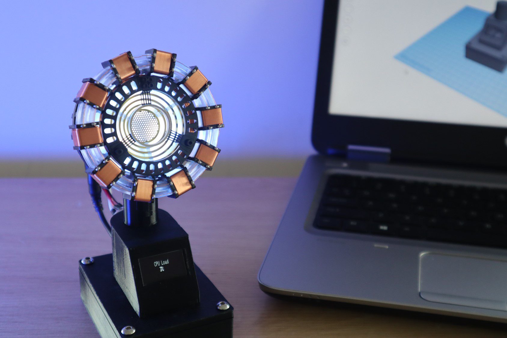
In this project, I’m going to be showing you how to turn one of these popular DIY arc reactor kits into a useful Arc Reactor CPU performance monitor for your computer. It plugs into one of your computers USB ports and displays your CPU performance on the OLED display and the arc reactor pulses according to your CPU usage, increasing the pulse frequency with an increased CPU load.
I started out by assembling an Arc Reactor kit, which has a built-in USB powered LED light and that got me thinking of a way to turn it into something useful for my desk. I initially thought about using an Arduino to make the LED pulse as some sort of readout or indication. This lead me to my computers CPU performance and I then decided to add the OLED display for a more accurate readout as well.
The arc reactor LED and OLED display are powered by an Arduino Uno in the base, which receives updates on the computers CPU usage every two and a half seconds and adjusts the pulse duration accordingly.
On the computer’s side, a python script reads the CPU performance data from a Hardware Monitoring application and posts this data to the Arduino through a serial communication port.
The device doesn’t need any external power, it is powered by the USB port as well.
Here’s a video of the build and the Arc Reactor in use, read on for the full step by step instructions as well as the code and print file downloads.
What You Need To Build Your Performance Monitor
- Arduino Uno – Buy Here
- USB A to B Cable – Buy Here
- Arc Reactor Kit – Buy Here
- 8050 NPN Transistor – Buy Here
- Current Limiting Resistor (500 ohm) – Buy Here
- OLED Display – Buy Here
- Ribbon Cable – Buy Here
- Male Pin Header Strips – Buy Here
- Female Pin Header Strips – Buy Here
- 4 x M3 x 8mm Hex Head Screws – Buy Here
- 4 x M4 x 8mm Hex Head Screws – Buy Here
- 1 x M5 x 8mm Hex Head Screws – Buy Here
You’ll also need to 3D print the components for the stand. If you don’t have a 3D printer and you enjoy DIY projects and building things, you should really consider getting one. They’ve become a lot more affordable and really expand your workshop capabilities.
How To Build Your Own Arc Reactor CPU Performance Monitor
I’ve split the build process up into a couple of steps to make it easier to follow. We’ll start by assembling the Arc Reactor (with is done according to the enclosed instructions), then solder the electronics, then assemble the base and finally upload the sketch and run the Python script.
Assemble The Arc Reactor
Theses Arc Reactor kits have been around for a couple of years and most of them are reasonably good quality, so you shouldn’t have any trouble following the enclosed instructions and assembling your reactor. There isn’t anything you need to modify or change during the build, you can even use one which is preassembled if you’ve got one you’ve already built.
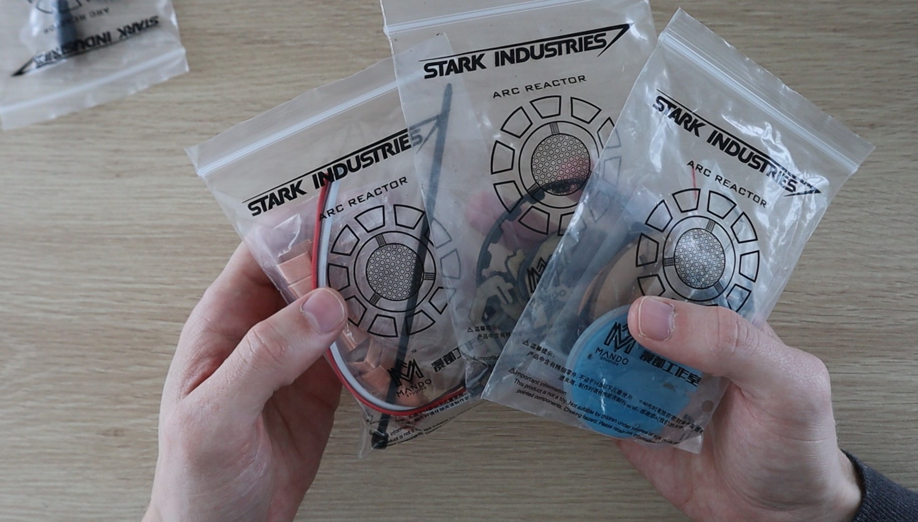
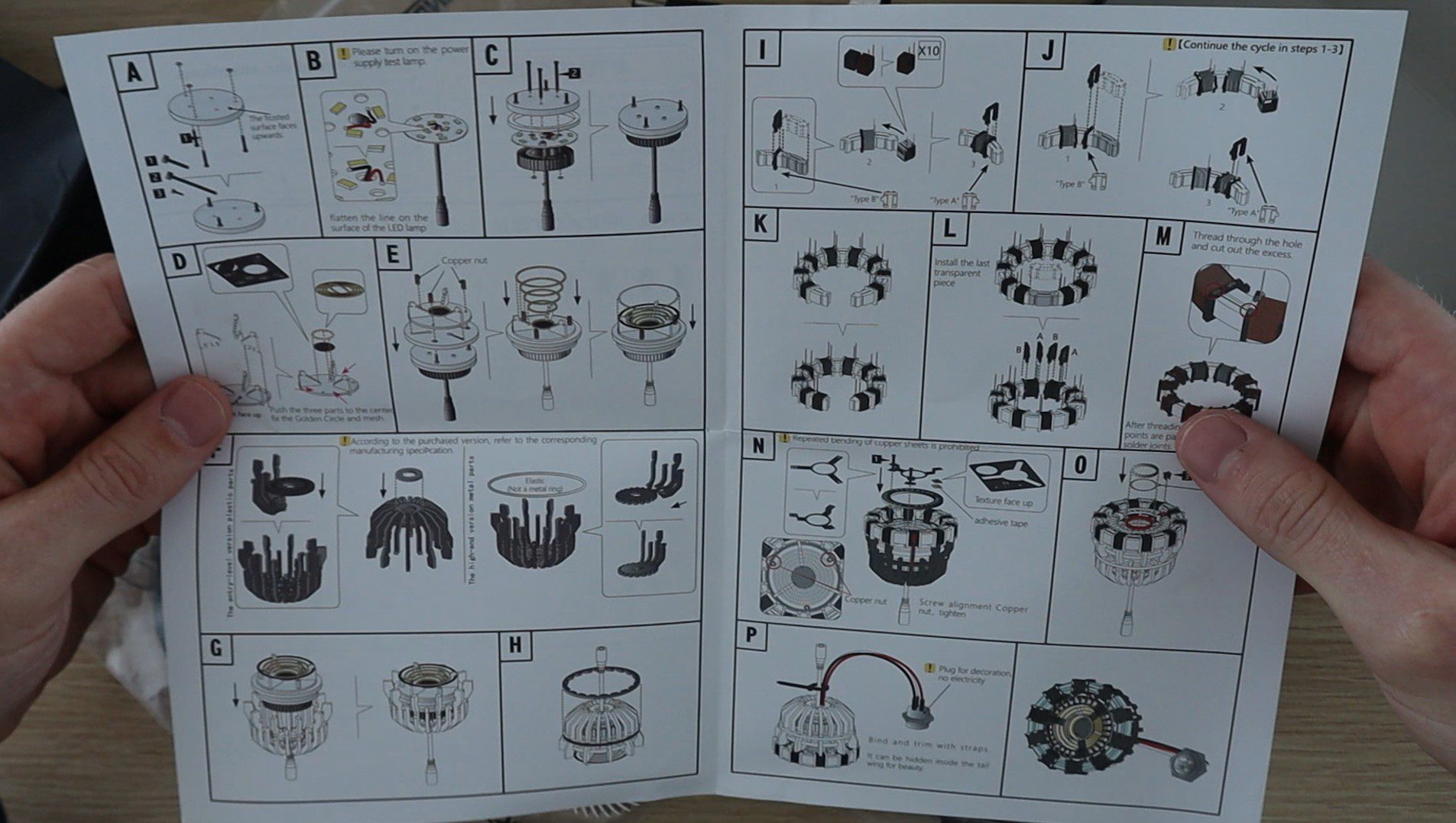
Depending on your kit, it should take around half an hour to an hour to assemble. Some kits do require you to wind your own coils or trim off a lot of excess plastic which can be time-consuming.
Solder The Electronic Components
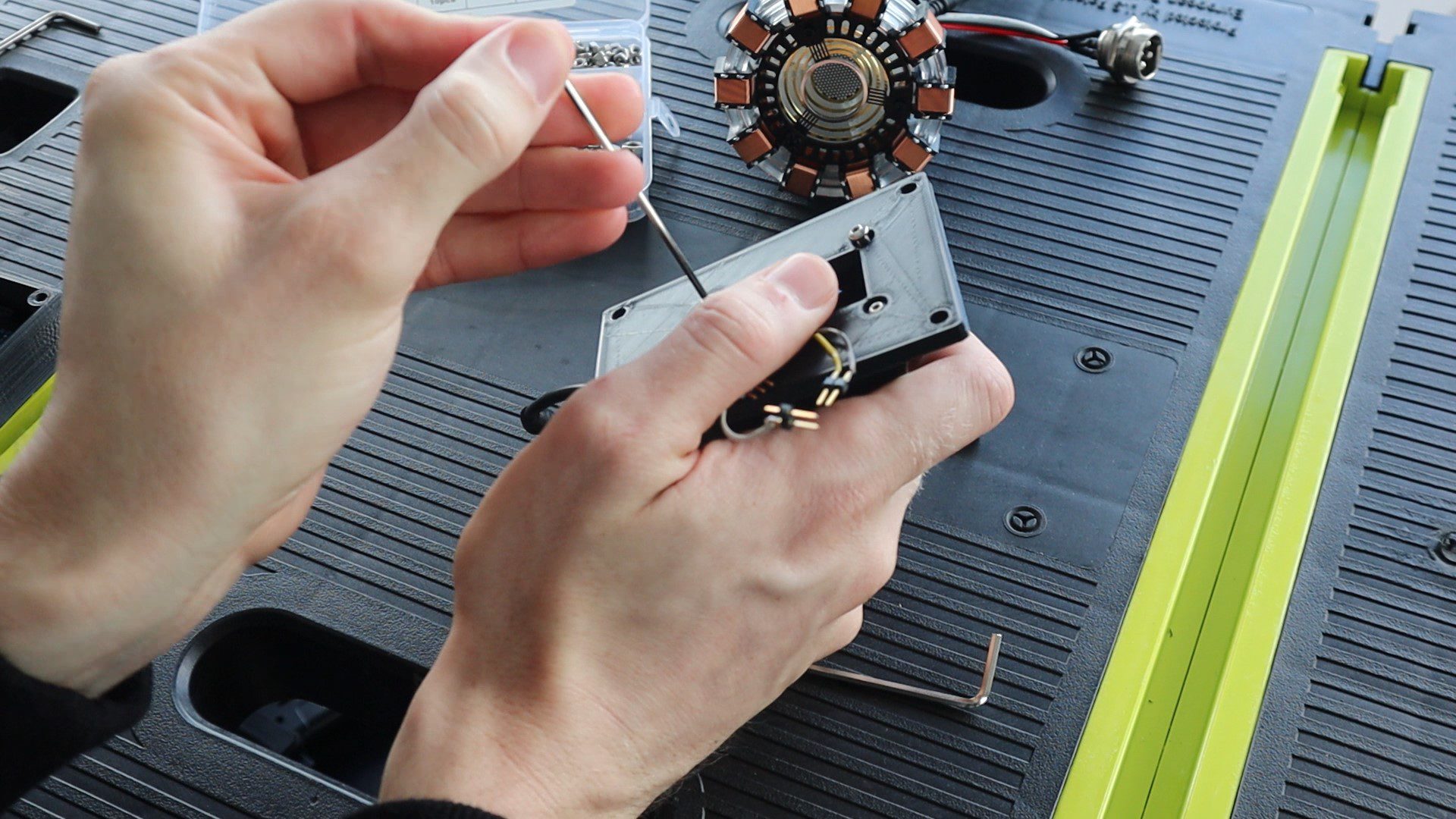
Before we assemble the base components, we need to make up the electrical circuit. The circuit for this project is quite simple and consists of an I2C connection between the Arduino Uno and the OLED display and then an NPN transistor connected to pin 5 of the Arduino to drive the Arc Reactor. The LED array on the Arc Reactor draws about 500 milliamps, which is too much to drive directly off of the Arduino. I added a 510Ω current limiting resistor onto the base leg of the transistor as well. I soldered this resistor directly onto the transistor and covered it with heat shrink tubing.
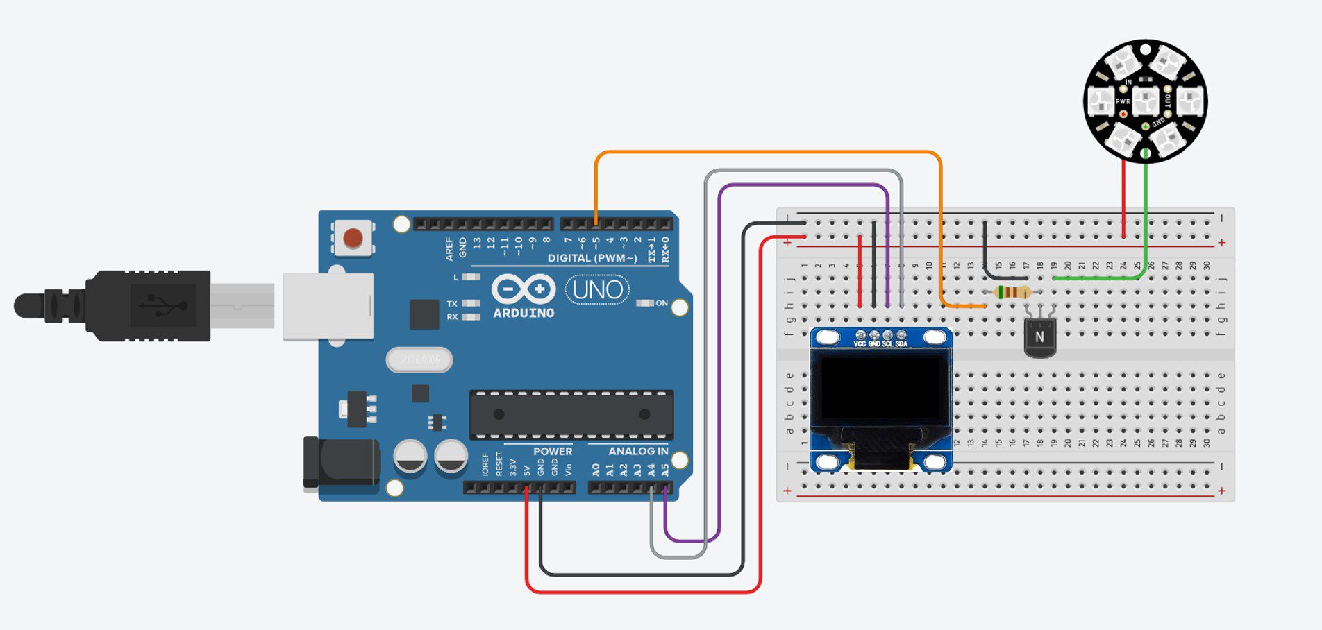
I connected the components using some coloured ribbon cable and header pins to plug into the Arduino and covered the exposed wiring on the transistor and plug with some heat shrink tubing.
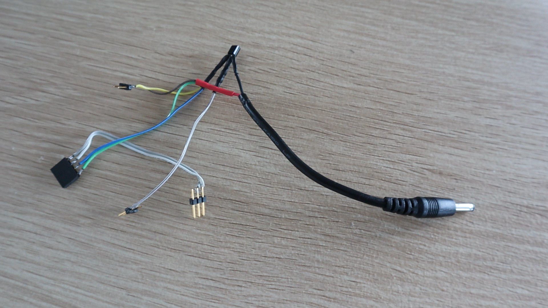
Important Note – There seem to be two variants of these OLED displays available online and they look very similar. One version has the GND pin first and the other the VCC pin first. They do not have any reverse polarity protection, so if you connect them the wrong way around they instantly “pop” and have to be thrown out. Make sure that you check this before soldering the pin connector.
Print & Assemble The Arc Reactor Stand
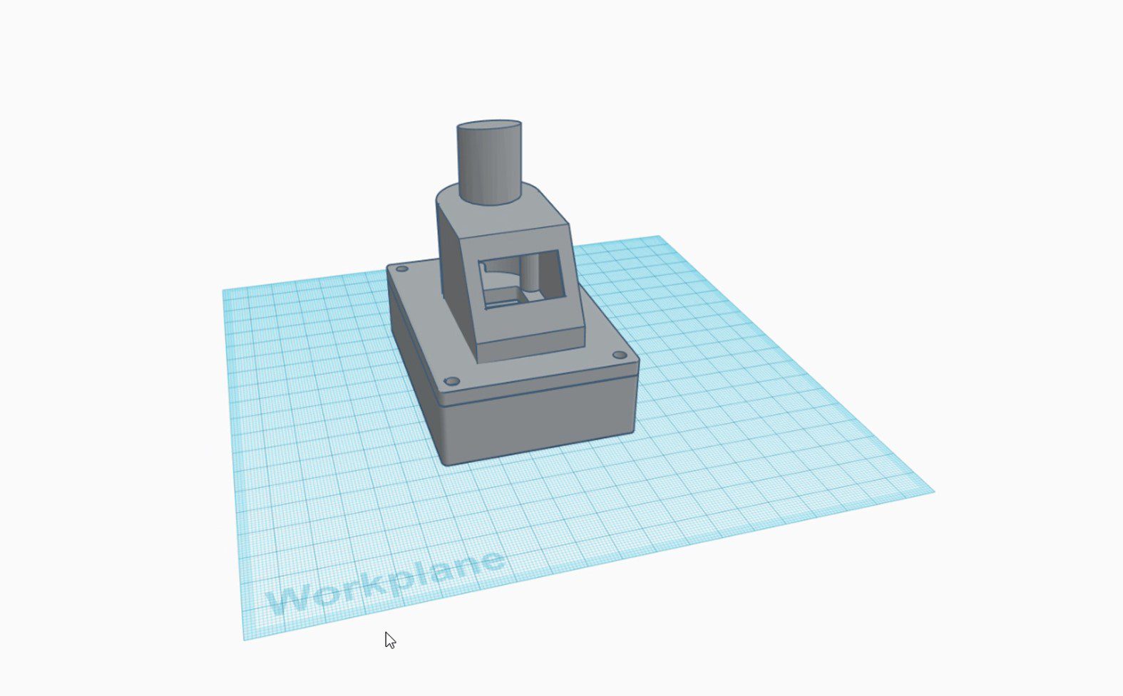
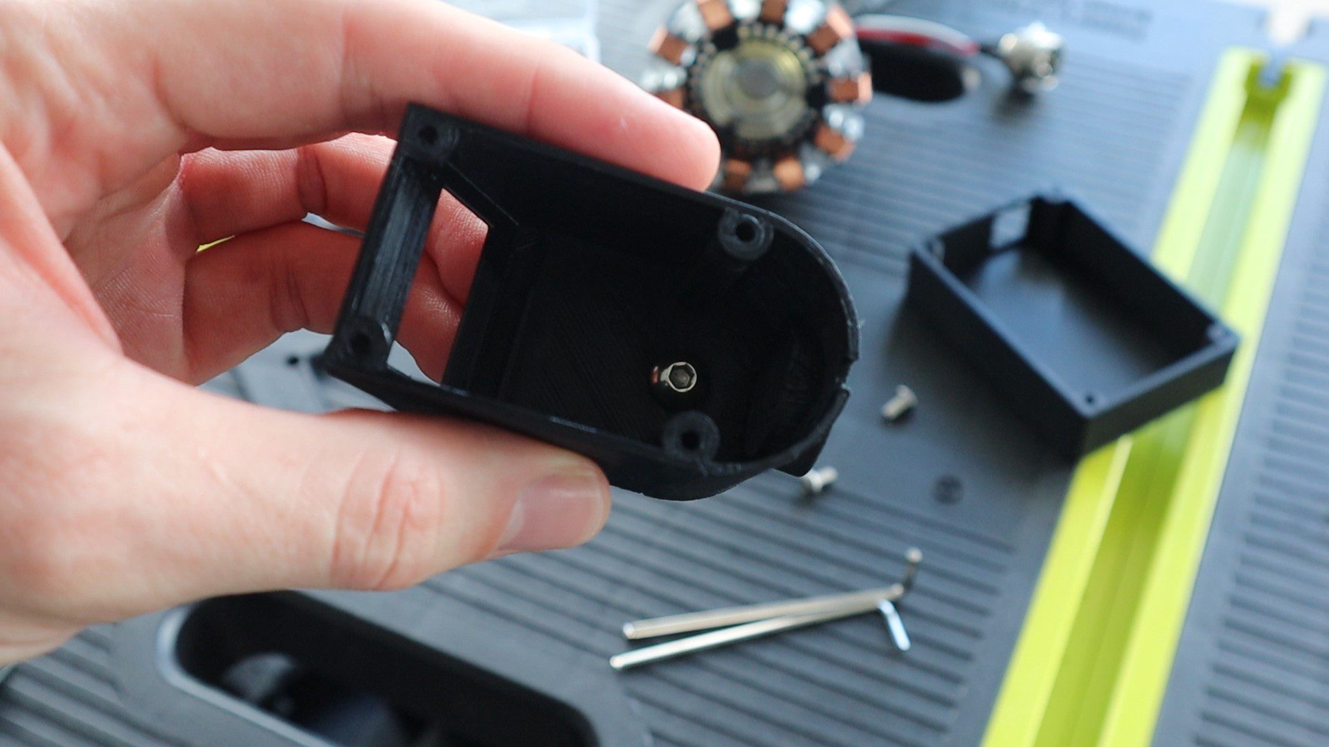
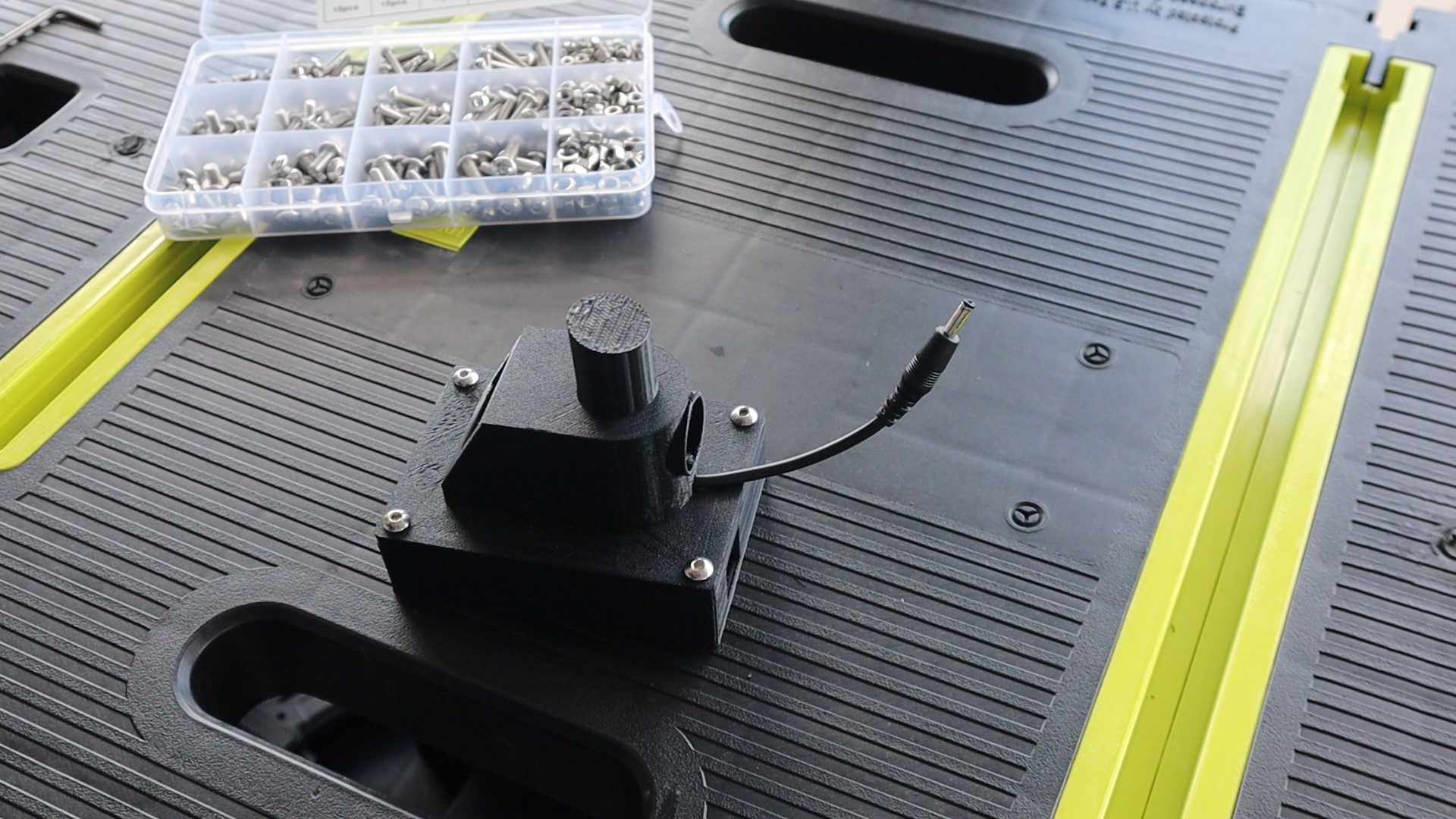
I designed four components which stack together with some hex head screws to make up the stand. There is a base compartment to house the Arduino. A cover to go over the base and connect to the display housing and then a post on top of the display housing to support the arc reactor.
Download The 3D Print Files – CPU Monitor Stand Files
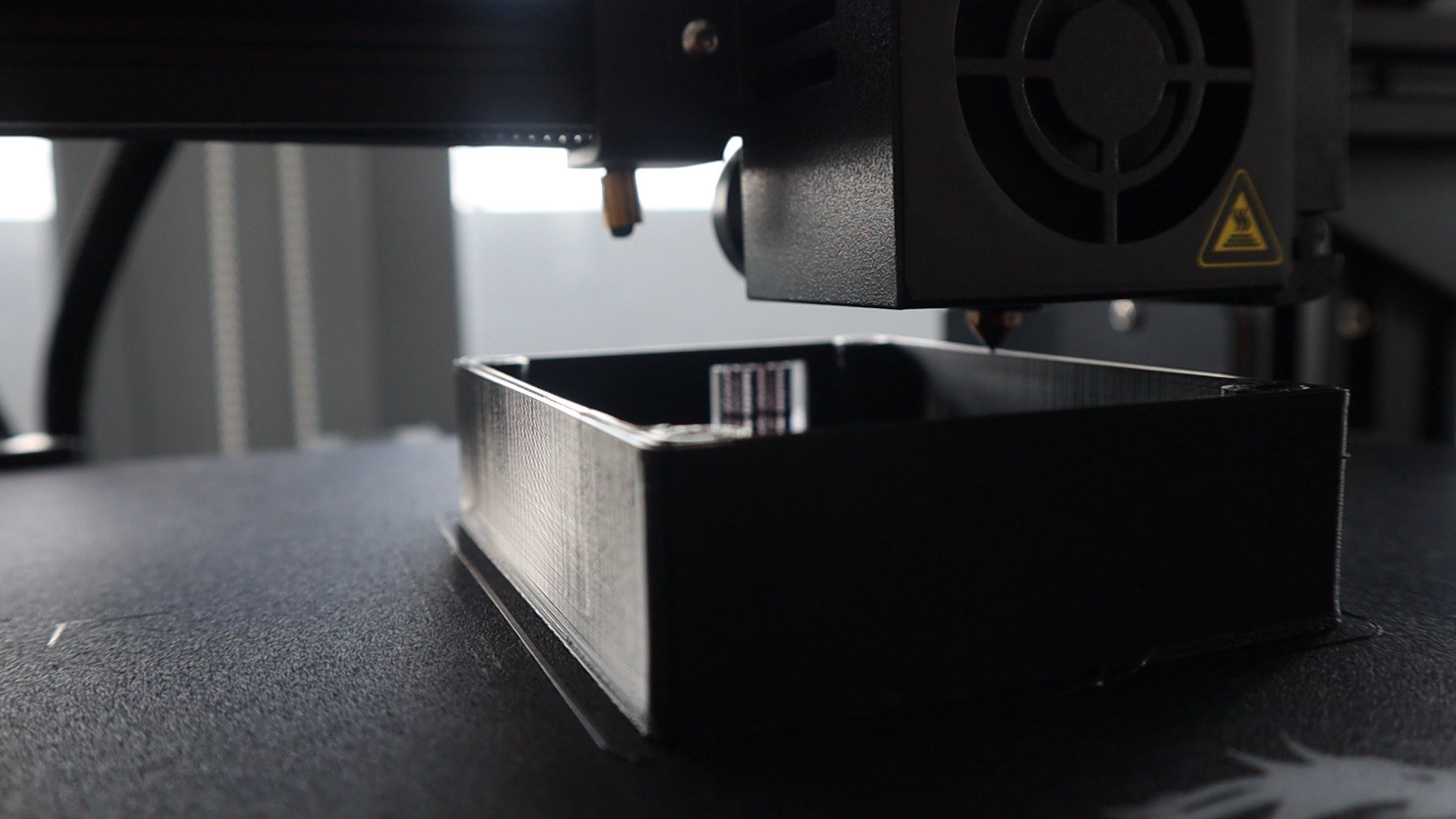
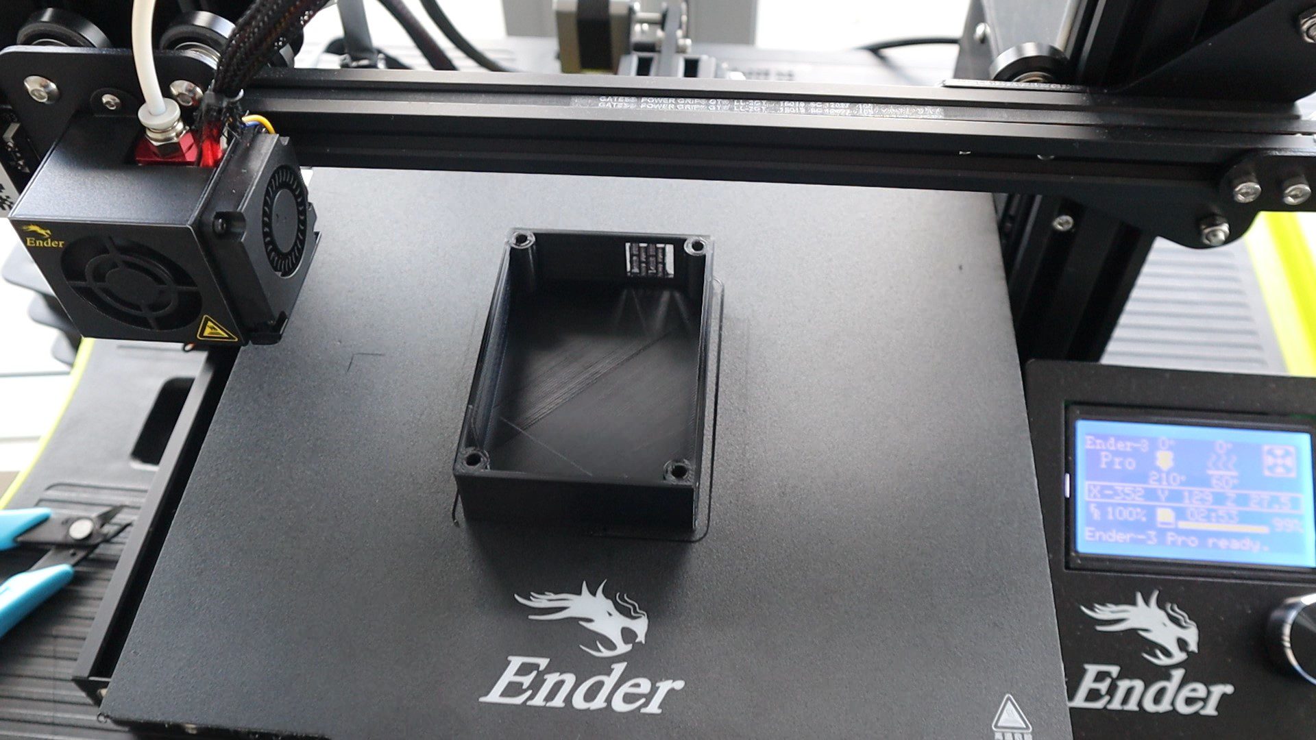
I 3D printed the components using black PLA with a 15% infill. You could print the base out of a different colour as well, it would probably look great in silver or grey too. I usually try to hide the screws underneath the housing, but in this design I wanted the screws to be visible to add a bit of detail to the base.
I’ve used a single M5 x 8mm hex head screw to secure the reactor post to the display housing. Make sure that the top surface of the post is angled to point the Arc Reactor slightly upwards, ie the highest point is in the front.
Then glued the OLED display into the housing using a glue gun.
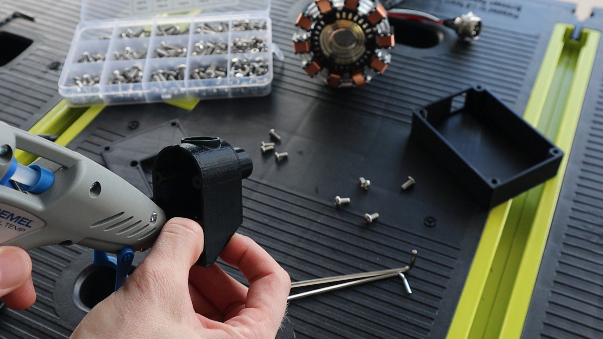
I then glued the Arduino Uno into the base, with the USB port lined up with the cutout.
I then plugged the connector into the OLED display and attached the Arduino cover plate using four M3 x 8mm screws.
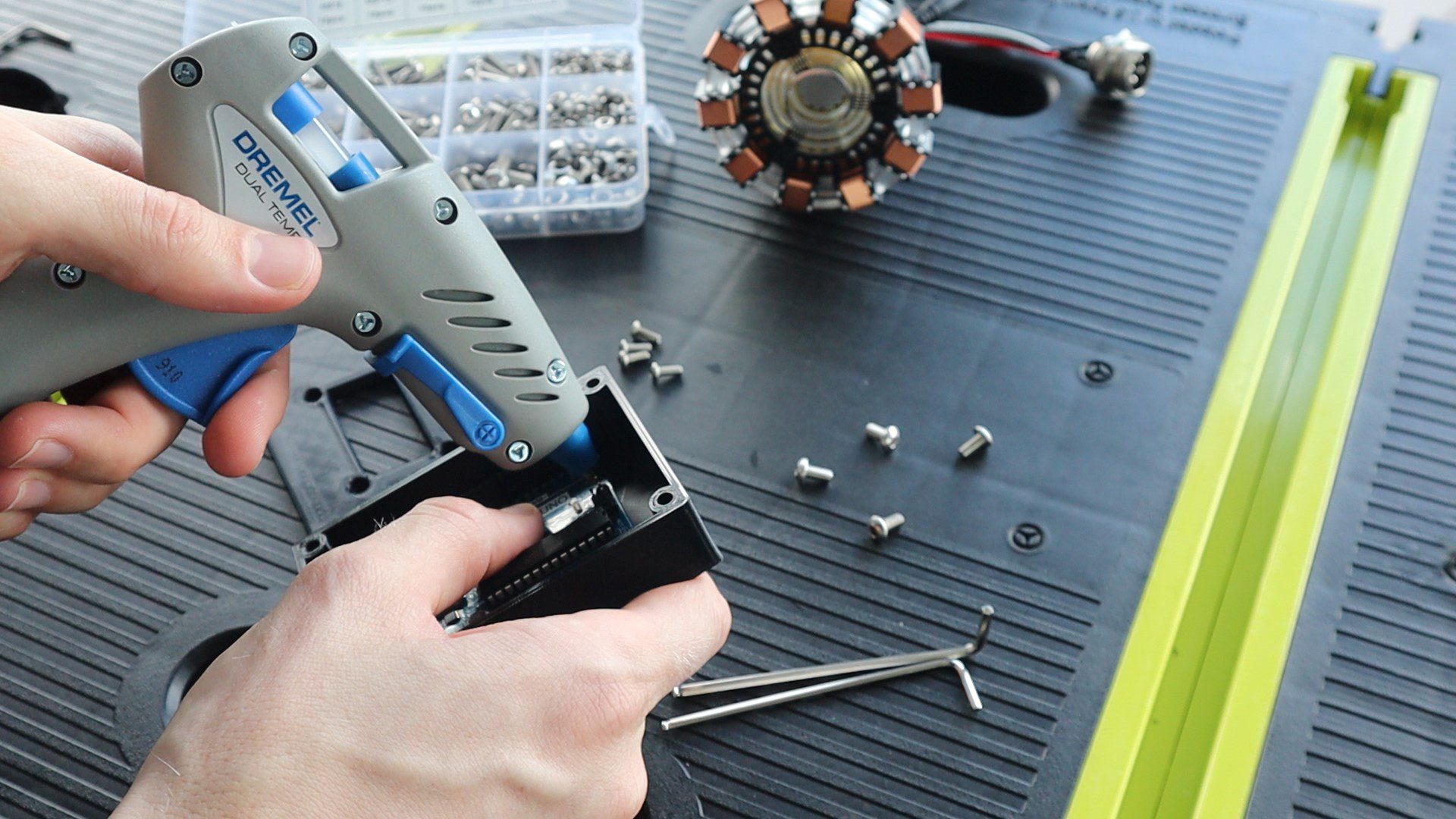
The cover then goes onto the base with four M4 x 8mm screws. I used M4 screws so that the heads are a bit larger and more visible on the base. You can switch these out for small M3 screws if you’d like, you’ll just need to modify the holes in the Arduino case to be slightly smaller.
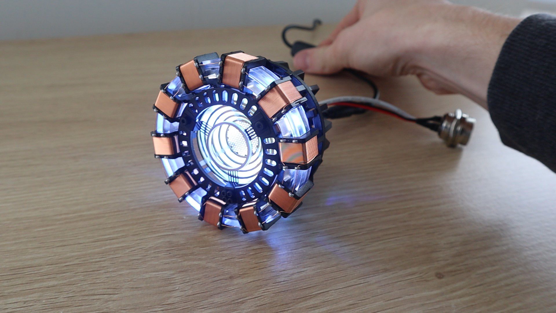
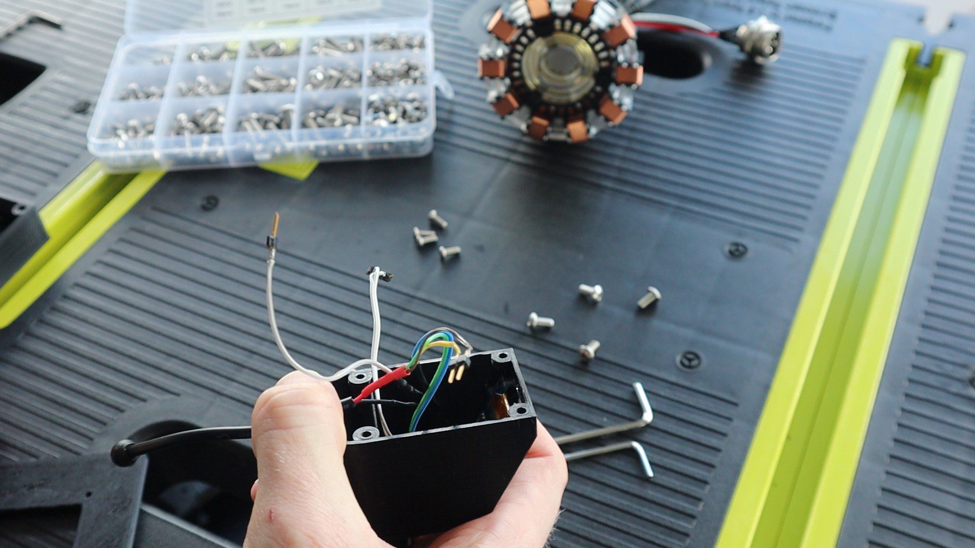
I attached the arc reactor to the base using the glue gun again. There isn’t really a nice flat surface on the bottom of the arc reactor, so you need to build up the glue around the supports until it’s held securely in place.
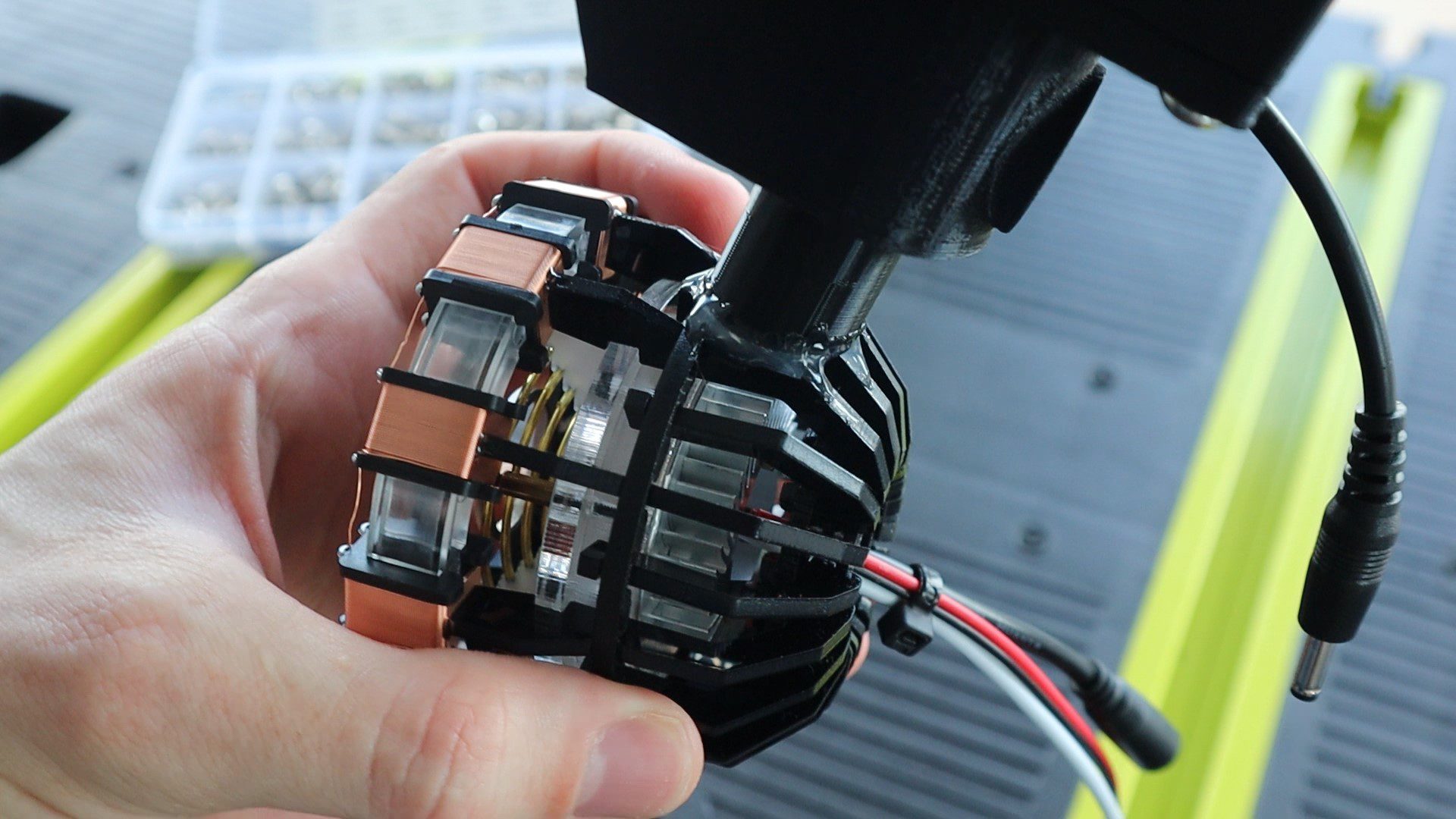
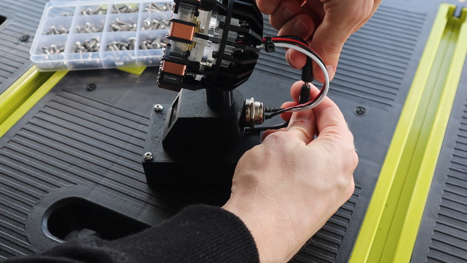
Lastly, glue the arc reactor plug into the back of the stand. This is just a dummy plug but it looks better if it’s actually plugged into something. If you’d like to neaten up the wiring even further, you could remove the existing plug on the LED and solder this plug’s leads onto the LED instead and then buy a real socket to plug the arc reactor into.

Remember to also connect the power lead to the LED.
And that’s the Arc Reactor CPU Performance Monitor’s hardware complete, now we just have to program it.
Programming The Arc Reactor CPU Performance Monitor
There are three things you need to set up to get your CPU data to be sent to your Arduino, a source of the data on your computer, a script to read the source on your computer and send the data through a serial communication port to your Arduino and the code on the Arduino to read the data, recompile it and then update the display and reactor LED.
We’ll start off with the Arduino’s code.
Programming The Arduino Uno
The Arduino’s code is fairly simple thanks to the OLED displays libraries. Most of the code is actually dedicated to turning the data received through the serial communication port back into usable data.
Let’s have a look at the code:
//Michael Klements
//The DIY Life
//Arc Reactor CPU Monitor
//25 May 2020

#include <SPI.h>                //Include the libraries for the display
#include <Wire.h>
#include <Adafruit_GFX.h>
#include <Adafruit_SSD1306.h>

#define SCREEN_WIDTH 128        //OLED display width, in pixels
#define SCREEN_HEIGHT 32        //OLED display height, in pixels

Adafruit_SSD1306 display(SCREEN_WIDTH, SCREEN_HEIGHT, &Wire, -1);   //Create the display object

int pinReactor = 5;             //Pin to reactor
int brightness = 25;            //How bright the reactor LED is at minimum. Its distracting if it turns off entirely.
int fadeAmount = 1;             //How many increments to fade the reactor LED by in each loop cycle

char receivedChars[5];          //Variables to track the incoming Serial data
boolean newData = false;

int cpuLoad = 0;                //Variable for the CPU load

void setup()
{
  Serial.begin(9600);                                     //Begin Serial communication with the PC
  if(!display.begin(SSD1306_SWITCHCAPVCC, 0x3C))          // Address 0x3C for 128x32 display
  {
    Serial.println(F("SSD1306 allocation failed"));
    for(;;);                                              //Don't proceed if it can't communicate with the display
  }
  display.clearDisplay();                                 //Clear the display
  display.setTextSize(1);                                 //Set the display text size
  display.setTextColor(SSD1306_WHITE);                    //Draw white text
  updateDisplay();                                        //Update the displayed CPU load, 0% initially
}

void loop()
{
  analogWrite(pinReactor, brightness);                    //Set the reactor LED brightness
  brightness = brightness + fadeAmount;                   //Increment the brightness by the fade amount
  if (brightness <= 25 || brightness >= 255)              //Reverse the direction of the fade increment once fully bright or dim
  {
    fadeAmount = -fadeAmount;
  }
  if (Serial.available())                                 //If an updated CPU load is received
  {
    delay(10);
    static byte ndx = 0;                                  //Index to keep track of received char position
    char endMarker = '%';                                 //Symbol indicating that the full CPU load value has been recieved
    char rc;                                              //Temporary variable to store the received char
    cpuLoad = 0;                                          //Reset CPU load variable to 0
    while (Serial.available() > 0 && newData == false)    //While data is being recieved
    {
      rc = Serial.read();                                 //Save data to rc
      if (rc != endMarker)                                //Check that the end of the data symbol hasn't been received
      {
            receivedChars[ndx] = rc;                      //Save char received to receivedChars array
            int temp = (int)rc - 48;                      //Convert ASCII char to int
            if(temp >= 0)                                 //Check that the converted char was not a space (ASCII 32)
            {
              if(ndx == 0)                                //Update CPU load based on 100s, 10s or units position
                cpuLoad = cpuLoad + temp*100;
              else if(ndx == 1)
                cpuLoad = cpuLoad + temp*10;
              else
                cpuLoad = cpuLoad + temp;
            }
            ndx++;                                        //Increment the index
        }
        else
        {
            receivedChars[ndx] = '\0';                    //Terminate the string
            ndx = 0;                                      //Reset the index
            newData = true;                               //Terminate the loop
        }
    }
    if (newData == true)                                  //Reset new data
    {
        newData = false;
    }
    updateDisplay();                                      //Update the displayed CPU load
  }
  int delayDuration = map(cpuLoad, 0, 100, 10000, 500);   //Maps CPU Load to a delay duration, higher load is a shorter fade time
  delayMicroseconds(delayDuration);                       //Wait the calculated delay duration
}

void updateDisplay ()                                     //Update the displayed text
{
  display.clearDisplay();
  display.setCursor(40,5);
  display.println(F("CPU Load"));
  display.setCursor(55,15);
  display.print(cpuLoad);
  display.print(F("%"));
  display.display();
}
Download the Sketch – ArcReactorCPUMonitor
We start off by importing the libraries necessary to control the OLED display, then set up the display parameters and create a display object.
We then define the Arc reactor LED control pin and set parameters for the initial brightness and the fade amount or difference in light intensity for each cycle. I created the initial brightness variable as a non-zero value so that the LED doesn’t turn off entirely between cycles, I found this “flashing” to be too distracting on my desk.
We then create a character array to receive the serial communication data and create a variable to store the CPU load.
In the setup function, we start the Serial communication, then establish a connection with the display and update it to display the initial CPU load, which will be zero. If the Arduino is not able to communicate with the display, the code will hang here and won’t continue into the loop. This is good for troubleshooting and makes sure that your Arduino is able to communicate with the OLED display
In the loop function, we start by updating the arc reactors brightness and then increment the brightness variable by the fade amount for the next loop cycle. We then have a check to see if the brightness has reached a maximum or minimum and if so, reverse the fade direction.
We then check if any Serial communication data is available. If there is data available then it is read into the character array until the % sign is received, indicating that the data is complete.
Data is transferred to the Arduino letter by letter in ASCII format, not as an integer. So each digit is received individually and the Arduino needs to know when the number is complete and then convert it into an integer. The rest of the code in this section does just that, converting each digit received into either hundreds, tens or units and then adding them together to form a complete integer which the Arduino can then quantify.
We then update the display to reflect the new CPU load and then map the CPU load to a delay duration between cycles, which corresponds to a faster or slower arc reactor pulse. The higher the CPU load, the faster the arc reactor will pulse.
Lastly, we have a function to update the display which just clears the previous display and displays the new CPU load.
While you’ve got your Arduino IDE open, also make a note of which com port is assigned to your Arduino Uno, as you’ll need to update this in the python script.
Getting Your CPU Load Data
In order to send the CPU load to your Arduino, we first need to be able to access it. One of the easiest ways to do this is using a freeware application called Open Hardware Monitor.
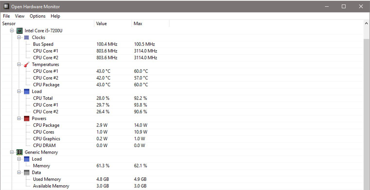
The Open Hardware Monitor app runs in the background on your PC and minimises to the system tray. It collects information on a number of different hardware items on your computer and makes it available to be read using a Python script.
You’ll need to make a note of your processor name displayed in the monitor as you’ll need to update this in the python script in order to access your CPU load.
You’ll also need to set the Open Hardware Monitor to run on startup so that you don’t need to open it every time you restart your PC. To do this, go to options and make sure that “Start Minimized”, “Minimize To Tray” and “Run on Windows Startup” are all checked. Then minimise the app.
Posting The Data To Your Arduino Using A Python Script
Lastly, we have a python script which transmits the CPU load through the serial com port to your Arduino. The script reads the data posted by the Hardware monitor app, finds the CPU load and then posts the value to the Arduino.
I didn’t write this code. I’ve modified the code from Leonidas Tsekouras’s Arduino PC Monitor example in which he sends a range of data to be displayed on an external LCD display.
Here is the code:
#!/usr/bin/env python
# -*- coding: utf-8 -*-

import json
import os
import time
from urllib.error import URLError, HTTPError
from urllib.request import Request, urlopen

import serial
import serial.tools.list_ports

serial_debug = False

def space_pad(number, length):
    """
    Return a number as a string, padded with spaces to make it the given length
    :param number: the number to pad with spaces (can be int or float)
    :param length: the specified length
    :returns: the number padded with spaces as a string
    """

    number_length = len(str(number))
    spaces_to_add = length - number_length
    return (' ' * spaces_to_add) + str(number)

def get_json_contents(json_url):
    """
    Return the contents of a (remote) JSON file
    :param json_url: the url (as a string) of the remote JSON file
    :returns: the data of the JSON file
    """

    data = None

    req = Request(json_url)
    try:
        response = urlopen(req).read()
    except HTTPError as e:
        print('HTTPError ' + str(e.code))
    except URLError as e:
        print('URLError ' + str(e.reason))
    else:
        try:
            data = json.loads(response.decode('utf-8'))
        except ValueError:
            print('Invalid JSON contents')

    return data


def find_in_data(ohw_data, name):
    """
    Search in the OpenHardwareMonitor data for a specific node, recursively
    :param ohw_data:    OpenHardwareMonitor data object
    :param name:        Name of node to search for
    :returns:           The found node, or -1 if no node was found
    """
    if ohw_data == -1:
        raise Exception('Couldn\'t find value ' + name + '!')
    if ohw_data['Text'] == name:
        # The node we are looking for is this one
        return ohw_data
    elif len(ohw_data['Children']) > 0:
        # Look at the node's children
        for child in ohw_data['Children']:
            if child['Text'] == name:
                # This child is the one we're looking for
                return child
            else:
                # Look at this children's children
                result = find_in_data(child, name)
                if result != -1:
                    # Node with specified name was found
                    return result
    # When this point is reached, nothing was found in any children
    return -1

def get_hardware_info():
    """
    Get hardware info from OpenHardwareMonitor's web server and format it
    """
    global serial_debug

    # Init arrays
    my_info = {}

    # Get data
    if serial_debug:
        # Read data from response.json file (for debugging)
        data_json = get_local_json_contents('response.json')
    else:
        # Get actual OHW data (Modify to your Open Hardware Monitor's IP Address)
        ohw_json_url = 'http://192.168.20.10:8085/data.json'
        data_json = get_json_contents(ohw_json_url)

    # Get info for CPU (Modify to your CPU name shown in Open Hardware Monitor)
    cpu_data = find_in_data(data_json, 'Intel Core i5-7200U')
    cpu_load = find_in_data(cpu_data, 'CPU Total')

    # Get CPU total load, and remove ".0 %" from the end
    cpu_load_value = cpu_load['Value'][:-4]

    my_info['cpu_load'] = cpu_load_value

    return my_info


def main():
    global serial_debug

    # Connect to the specified serial port (Modify to your Arduino's COM port)
    serial_port = 'COM3'
    if serial_port == 'TEST':
        serial_debug = True
    else:
        ser = serial.Serial(serial_port)

    while True:
        # Get current info
        my_info = get_hardware_info()

        # Prepare CPU string
        cpu = space_pad(int(my_info['cpu_load']), 3) + '%'

        # Send the strings via serial to the Arduino
        if serial_debug:
            print(arduino_str)
        else:
            ser.write(cpu.encode())

        # Wait until refreshing Arduino again
        time.sleep(2.5)


if __name__ == '__main__':
    main()
Download The Code – ArduinoPCMonitor
You’ll need to update the IP address that your Open Hardware Monitor is posting the data too. This can be found in the Open Hardware Monitor app by going to Options -> Remote Web Server -> Port.
You’ll also need to change your processor name and check that the Arduino’s com port is correct.
Both the python script and then hardware monitor can be set to automatically startup with your computer and run in the background, so you don’t have to keep running them every time you turn your computer off. The python script can be automatically started using the windows “Start a Program” utility.
Using The Arc Reactor CPU Monitor
Upload the code your Arduino and make sure that the Open Hardware Monitor app is running on your computer and then run the Python script to start posting the data to your Arduino. You should then start seeing updates to your CPU performance on the OLED display and the reactor pulsing accordingly.
On start-up, with no data being transmitted, the OLED display should still display CPU Load 0% and the reactor should be pulsing slowly.
If you open up a benchmarking application to increase the CPU load to 100%, you will see it pulse really quickly.
You can make your own adjustments to the pulse durations and brightness levels in the code. I found it too distracting to have the pulse turn off completely each cycle, so I limited the minimum brightness and also set the low CPU usage pulse duration to be quite long. You can edit these by making changes to the mapped delay, to the brightness variable and to the fadeAmount variable.
Let me know if you’re going to be building your own arc reactor CPU performance monitor or what you’ve done with an arc reactor you’ve built.
Share This Guide
??awesome