A while ago, I made a soil moisture monitoring stick that gives you some useful information about the soil moisture level for your indoor plants.
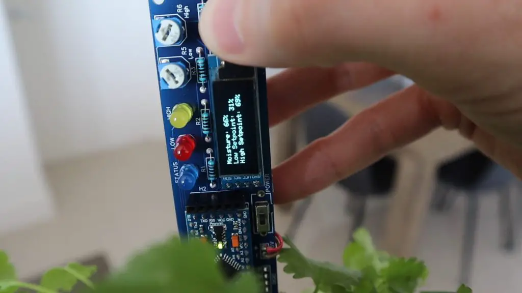
It does a great job, providing indication LEDs and giving you a numerical readout of the moisture content of the soil, but it looks quite ugly stuck into your pots and it’s not easy to see the flashing LEDs from far away. This got me thinking of a way to make a better-looking moisture level indicator which could give you all of the basic information you need at a glance, a smart indoor plant base.
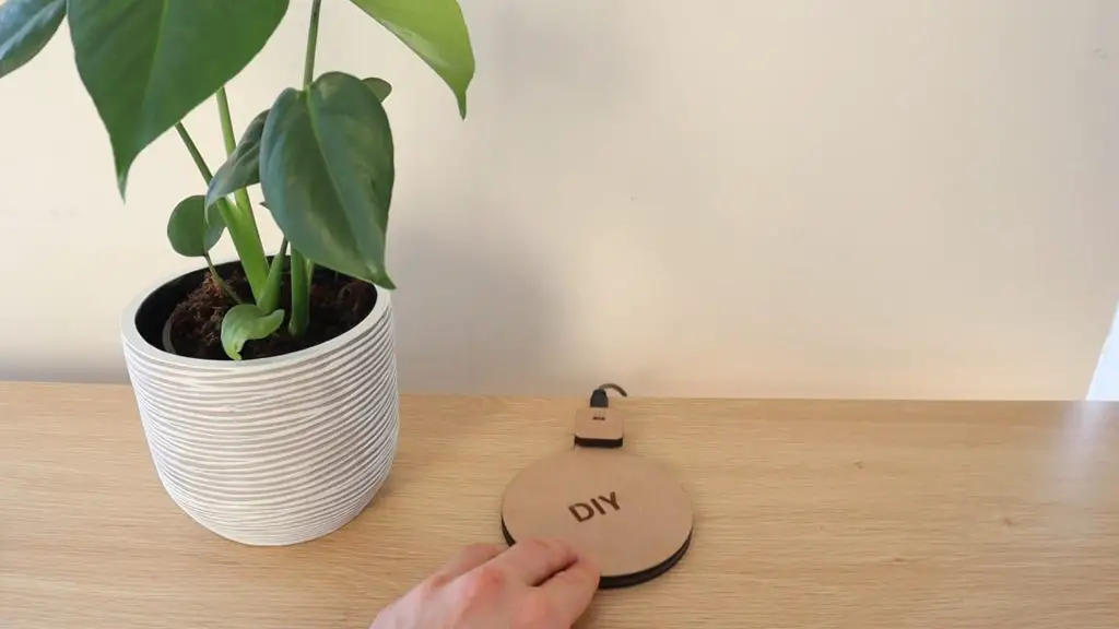
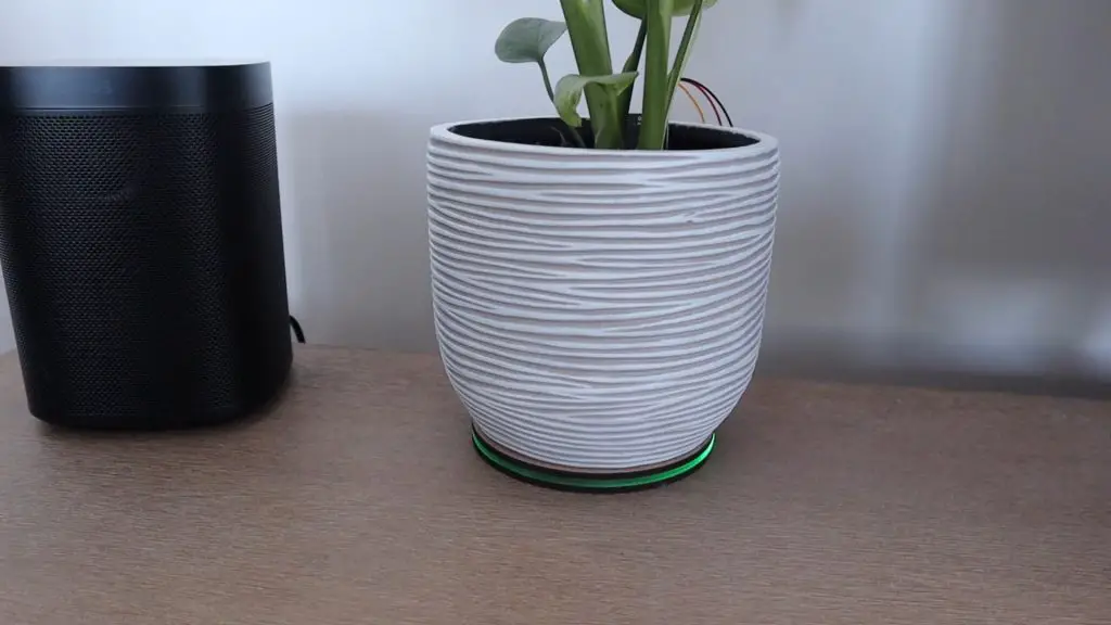
After throwing around a couple of ideas, I thought of making a round base for the pot to stand on, similar to a coaster, with an indicator layer which could be lit up in different colours to indicate whether your plant needs some attention.
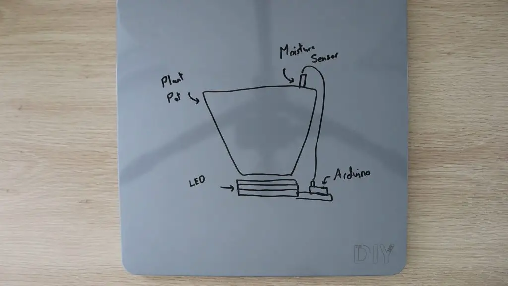
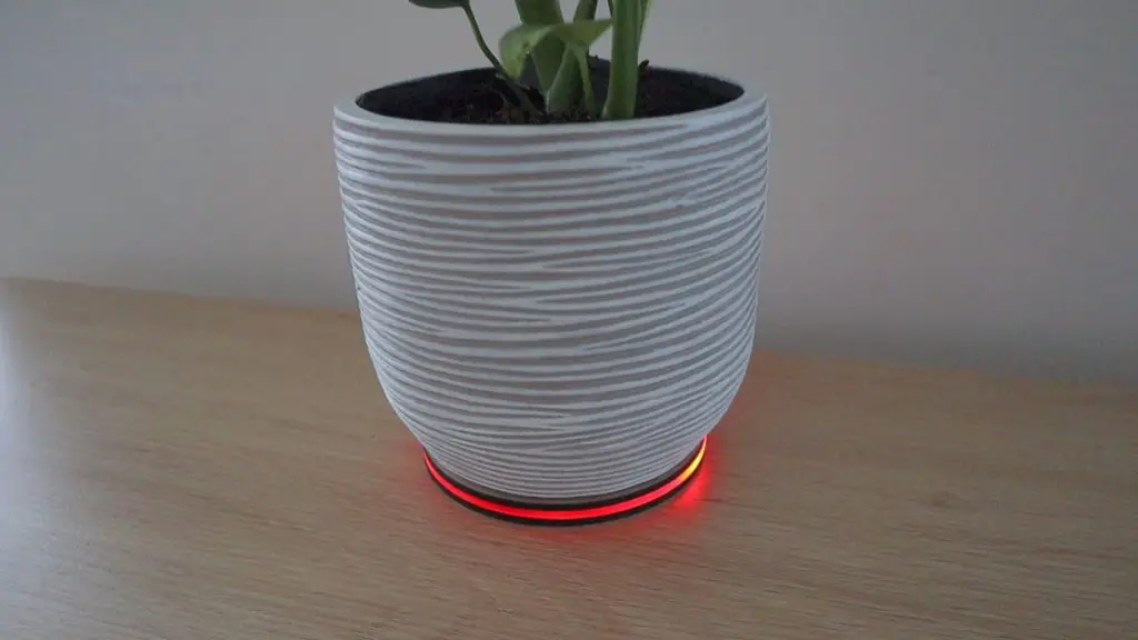
The indicator layer would be lit up in green when the plant had enough water and red when it needed more water. I could also create a colour fade between these two limits as a sort of level indicator. So a greeny-yellow would mean that there’s still a fair amount of water, while an orangy-yellow would mean that you’d need to water the plant soon.
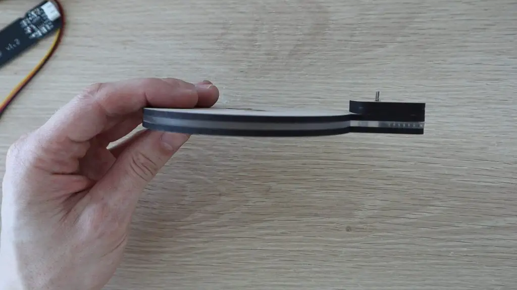
I didn’t want the base to become bulky and unattractive as well, so I wanted to keep it as thin as possible.
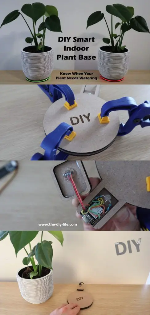
Here’s a video of the build and the smart indoor plant base in use, read on for the full step by step instructions.
What You Need To Make A Smart Indoor Plant Base
- Seeeduino Xiao – Buy Here
- Or Seeeduino Xiao From Amazon – Buy Here
- Capacitive Soil Moisture Sensor – Buy Here
- 5mm RGB LED – Buy Here
- 100Ω Resistor – Buy Here
- 220Ω Resistor – Buy Here
- Ribbon Cable – Buy Here
- Female Header Pins – Buy Here
- 3mm MDF – Buy Here
- 3mm Acrylic – Buy Here
- Epoxy Adhesive – Buy Here
Building The Smart Indoor Plant Base
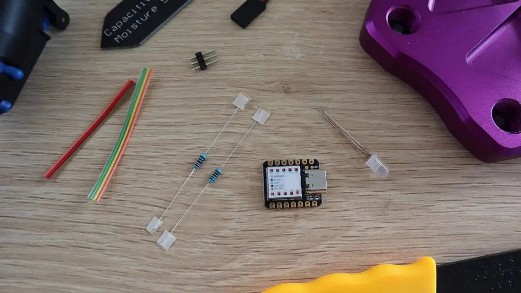
Get Your Components Together
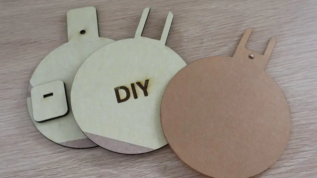
I decided to use a layer of 3mm acrylic wedged between two layers of 3mm MDF. An RGB LED on the back would illuminate the edges of the acrylic to be green when the plant was healthy and red when it needed some attention, with the levels in between being varying shades of yellow.
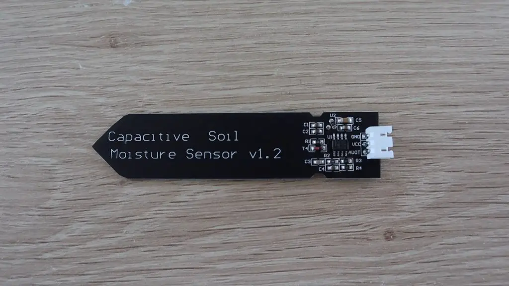
I’ll still be using the same soil moisture sensor that I used previously, only now it won’t have any other electronics attached to it, all of the processing will be done in the base by the small microcontroller.
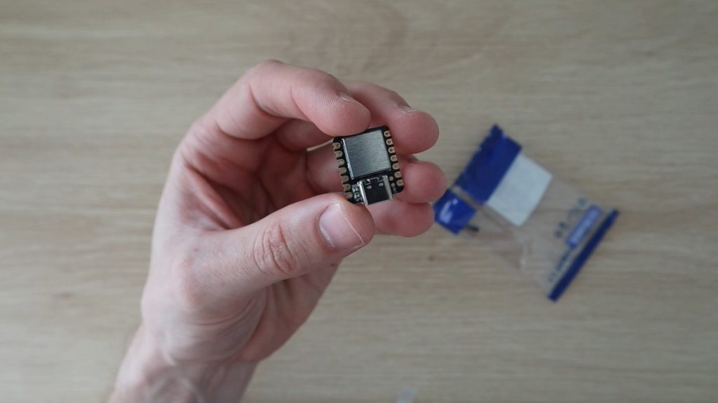
The microcontroller I decided to use was this Seeeduino XIAO. It’s really small, has an ARM Cortex CPU, and is Arduino compatible, so it’s easy to program and interface with the components. The best part is that they cost just $5 from Seeed Studio.
Designing The Smart Indoor Plant Base
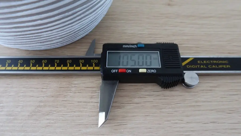
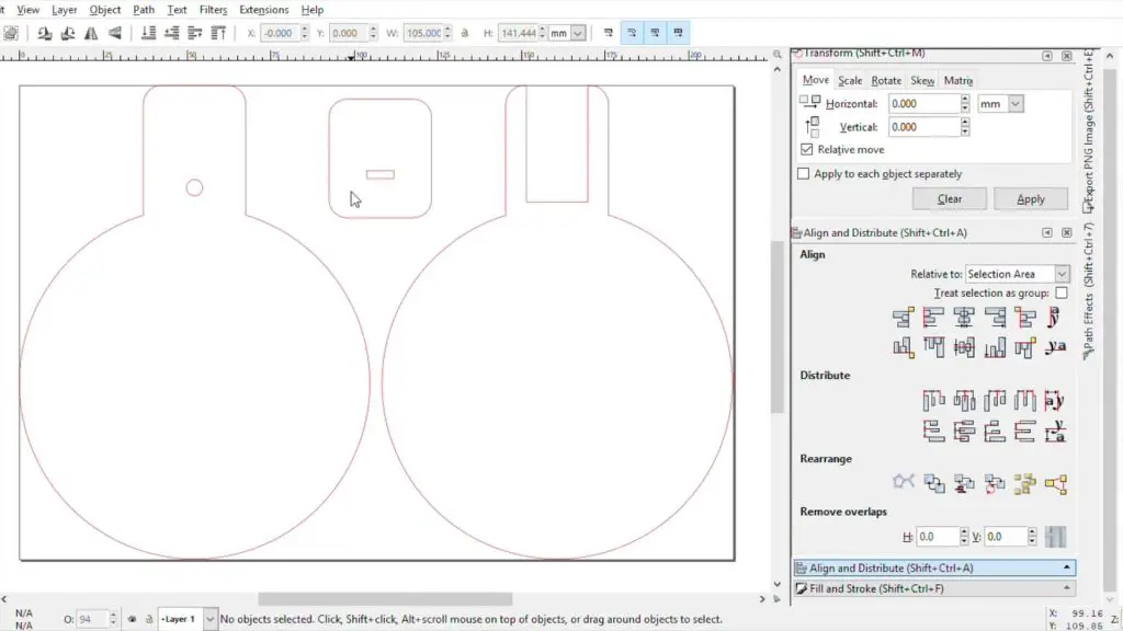
I started out by measuring the base of the pot so that I could design the new base to be slightly larger. I designed the three circular layers of the base and the small enclosure at the back to house the Arduino.
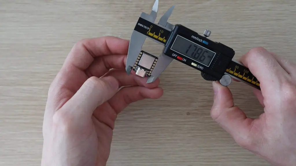
The Arduino has a built-in USB C port for power, so it’s easy to just plug the base into a USB outlet using a USB C cable to power it once it’s built.
The components were designed in Inkscape so that they can be exported for laser cutting.
Assembling The Base Components
Once the components were designed, I cut them out on my laser cutter.
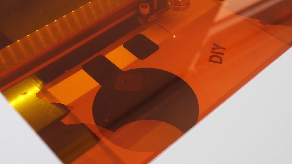
If you don’t have a laser cutter, you can also easily cut MDF and acrylic with a hand saw. Just print out the PDF template supplied with the laser cutting files and trace them out onto your MDF and acrylic.
In order for the edges of the acrylic to light up evenly, you need to roughen them with some sandpaper so that they’re opaque. The rough edges diffuse the light and make the acrylic layer look as if it is lit up entirely.
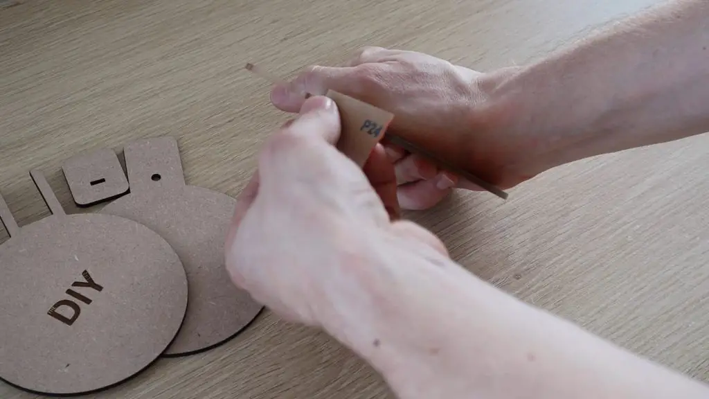
I used some 240 grit sandpaper until they had an even white appearance all around.
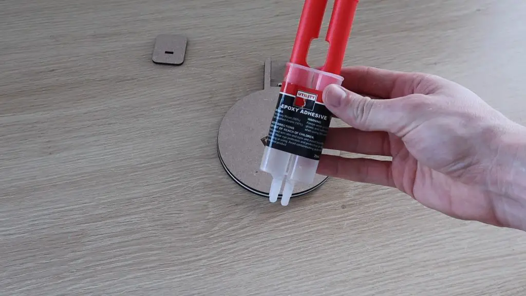
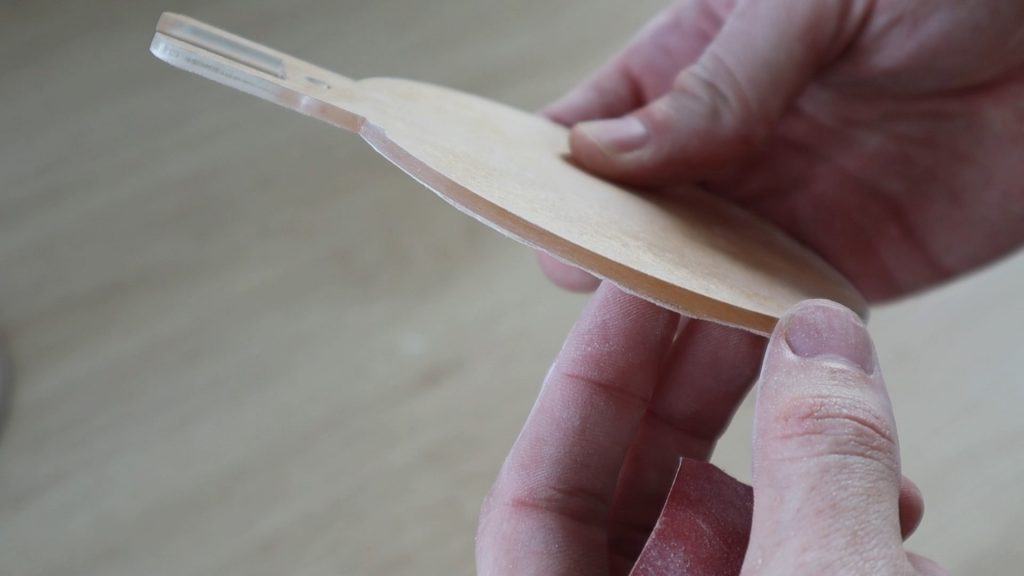
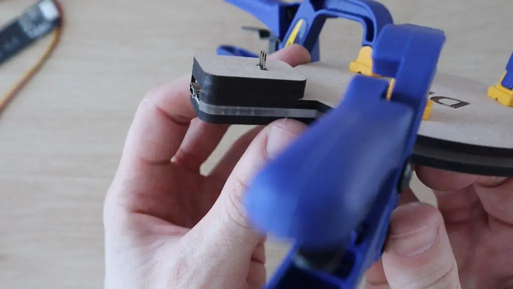
Next, I glued the three layers together using some epoxy adhesive.
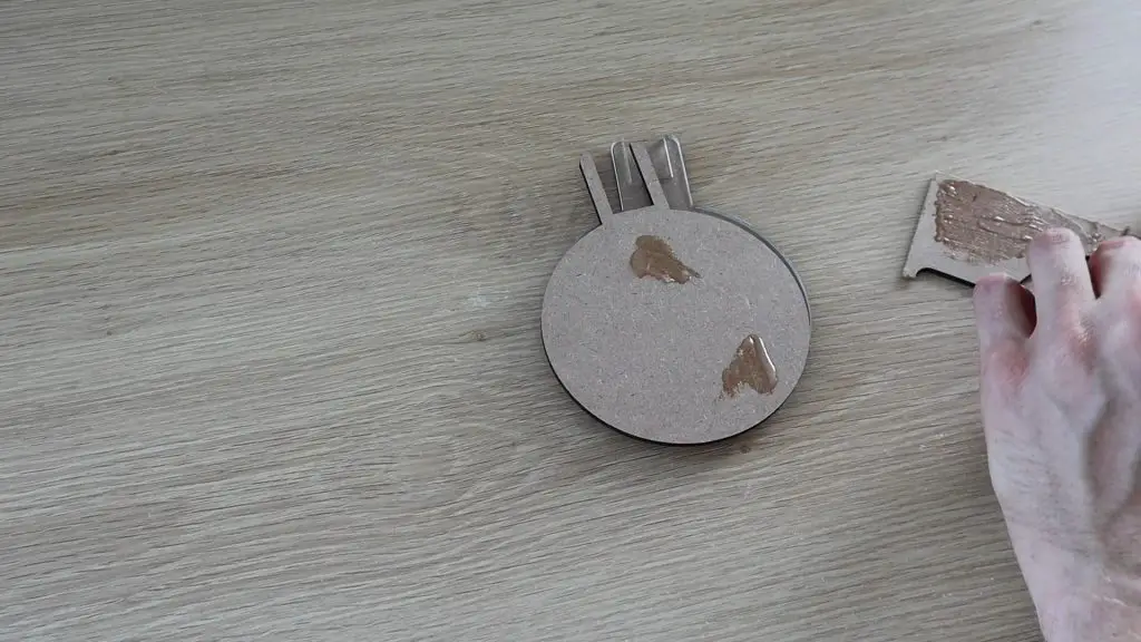
Use a small amount of epoxy, you don’t want it to seep out of the edges and onto the areas you’ve just sanded or you’ll need to sand them again.
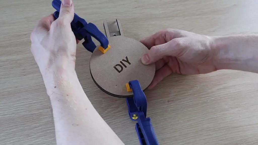
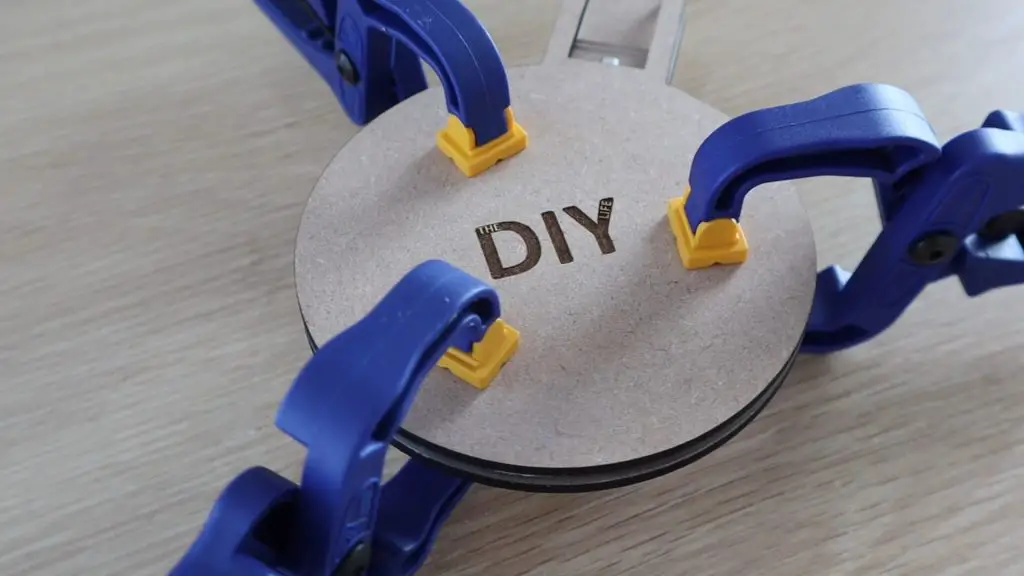
I used some small tool clamps to hold the layers in place while it cured.
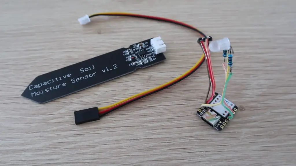
Solder The Electronic Components Together
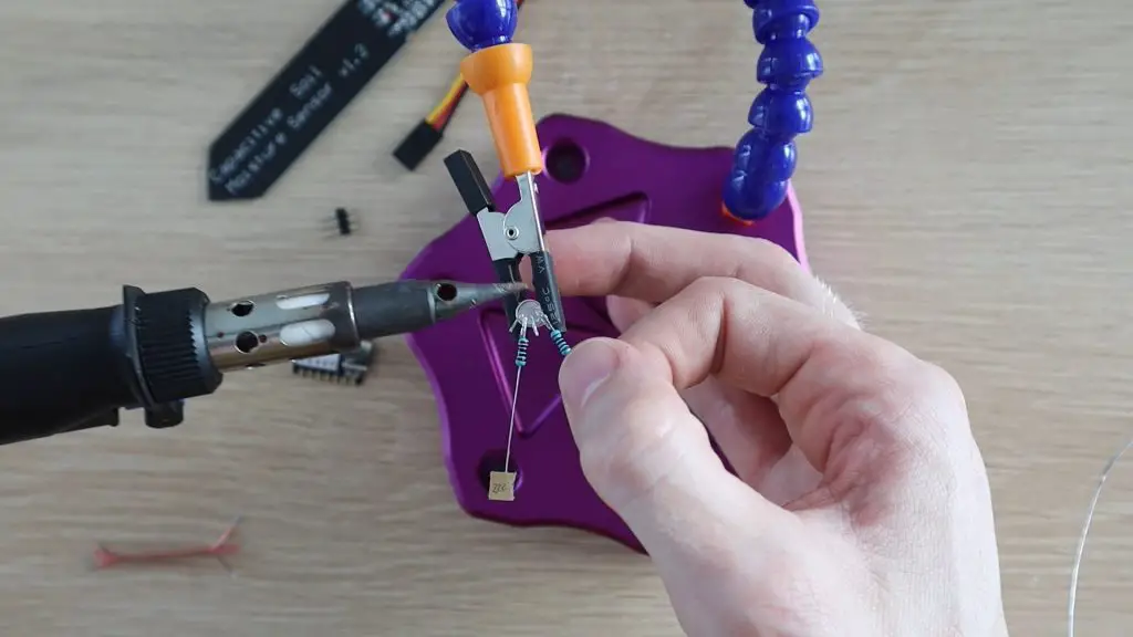
While the epoxy was curing, solder the electronic components together.
The circuit is not very complex as you’ve only got two components to interface with the Arduino, the sensor and the LED:
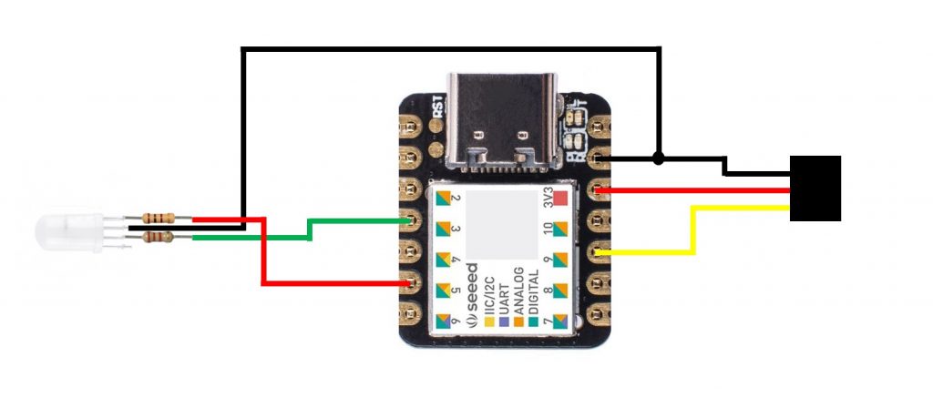
You need a current limiting resistor on each leg of the LED, 100Ω on the red leg and 220Ω on the green leg, and some header pins to plug the moisture sensor into. The green light from the LED tends to be more intense and washes out the other colours, so I used a higher resistance on the green leg than the red leg to balance it out.
I connected my soil moisture sensor the 3.3V output on the Arduino. I have noticed that some of these sensors don’t run reliably (or some even at all) on 3.3V, although they are supposed to be able to accept 3.3V to 5V. If yours is not working correctly, try powering it from the 5V supply on the Arduino – VCC. The sensor steps the voltage down in any case, so you’ll still only be supplying 3.3V back to the analogue input. Be careful if you’re using a different sensor as this Arduino’s analogue inputs can only accept a maximum of 3.3V.
Install The Electronics Into The Base
Next, you’ll need to install your soldered electronics into the housing at the back of the base.
When I tried to assemble my electronic components I saw that I had been a bit optimistic in thinking I’d get all of the components into the two-layer space. So I cut an additional spacer to create a bit more headroom. This spacer is included in the cutting file download and should be glued to the underside of the top cover.
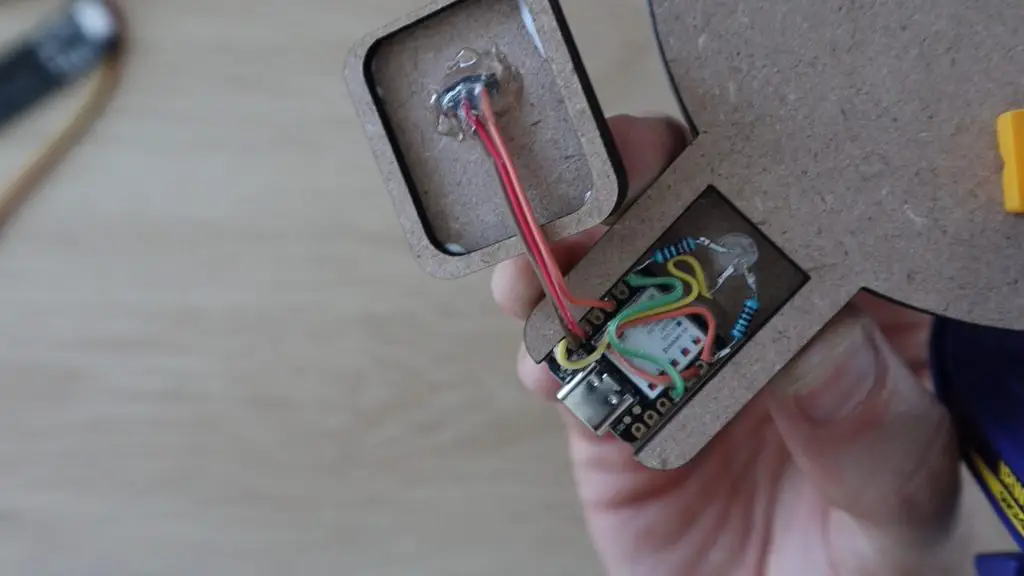
Push your LED into the hole in the acrylic, not too far as you want the brightest part to be in the acrylic layer. Then glue your Arduino into the housing and glue the pins into the cover layer. It’s a good idea to cover up the soldered joints on the header pins so that they don’t short out on the LED legs when you assemble it.
Lastly, close the housing up. I used a glue gun as it’s quicker to work with, but you can use your epoxy adhesive as well.
That’s it for the assembly, now we just need to program and calibrate it.
Programming The Arduino
The sketch is quite simple, it just takes analogue readings from the moisture sensor and then adjusts the LEDs proportionally between two limits.
You’ll need to calibrate and set the two limits up according to your own plant as some plants need more water and some can survive in dryer soil. Essentially you want the LED to be red when you need to water it and go green once you’ve given it enough water, you shouldn’t need to over-water the plant to get the base to turn green. There’s more about this setup step later on.
In my first revision of the sketch I just updated the LEDs with the value read from the sensor. I noticed that there was some variation between measurements and every so often there was a value significantly higher or lower which caused weird colour flicker to occur.

So I switched to a moving average system where the average of the past ten readings is taken and this produces much more consistent results and a slow fade when you water the plant. This is why the code looks a bit more complex than it should have been.
Here is the final version of the sketch:
//The DIY Life
//Michael Klements
//26 September 2020

#define greenLED 3                                        //Define the IO pin numbers
#define redLED 5
#define moisturePin 9

#define wetCal 750                                        //Wet and dry calibration limits
#define dryCal 1023

int measurements [10];                                    //Array to store the last 10 measurements
int counter = 0;                                          //Counter to keep track of the current array position

void setup()
{
  pinMode(greenLED, OUTPUT);                              //Define the pin modes
  pinMode(redLED, OUTPUT);
  for (int i=0; i<=9 ; i++)                               //Populate the array with starting readings from the sensor
    measurements [i] = analogRead(moisturePin);
}

void loop()
{
  addData(analogRead(moisturePin));                                       //Take a new reading and add it to the array
  int moistureLevel = getAverage();                                       //Get the new average of array readings
  if(moistureLevel > dryCal)                                              //Constrain reading between the high and low limits
    moistureLevel = dryCal;
  else if(moistureLevel < wetCal)
    moistureLevel = wetCal;
  int greenBrightness = map(moistureLevel, dryCal, wetCal, 0, 255);       //Calculate the green and red LED brightness according to the reading
  int redBrightness = map(moistureLevel, wetCal, dryCal, 0, 255);
  analogWrite(greenLED, greenBrightness);                                 //Set the green and red LED brightness
  analogWrite(redLED, redBrightness);
  delay(2000);
}

void addData(int num)                                                     //Function to add a reading to the array and increment the counter
{
  measurements [counter] = num;
  if (counter < 9)
    counter++;
  else
    counter = 0;
}

int getAverage()                                                          //Function to return the average of all readings in the array
{
  int ave = 0;
  for(int i=0; i<=9 ; i++)
    ave = ave + measurements [i];
  ave = ave/10;
  return ave;
}We start by defining the IO pin numbers and the calibration limits, we then have an array to store the last ten readings and a counter to keep track of the array position being updated.
In the setup function, we define the pin modes and then populate the array with ten initial readings from the sensor as a starting point.
In the loop function, we take a new reading and call the addData function to add the reading to the array in the current position. We then get a new average value for the array before checking that the value is within the wet and dry limits. If it is not, it is limited to a maximum and minimum, being the two limits.
We then map the average moisture level to a corresponding green and red led brightness and then set the LED brightness accordingly using a PWM output. We then wait 2 seconds before repeating the loop.
We then have two functions, addData and getAverage which manage the data in the array. The addData function just adds the latest measurement to the array at the current position and then increments the counter. The getAverage function returns the average of all of the values in the array.
Calibrate the Sensor
As mentioned previously, you’ll need to calibrate your sensor in order to get meaningful results from the base. The best thing to do is to start when your plant soil is “dry” or at a level where you’d expect to need to water your plant again.
Place your plant onto the base, push the sensor into the soil, and plug it into the header pin socket.
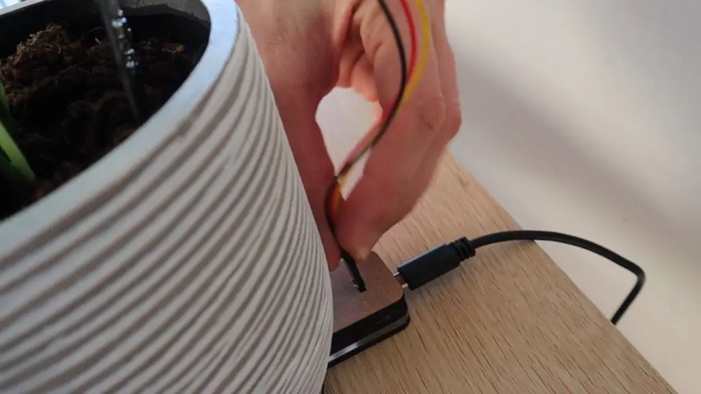
Connect the Arduino to your computer using a USB C cable, and open up your Serial monitor on your Arduino IDE. Output the soil moisture readings to the monitor, one every second or two, and note the average of around 10-20 readings once they’ve stabilised (aren’t varying significantly). This will be your dry setpoint.
Once you’re happy with your dry readings, you’ll need to water the plant. Water your plant as you would normally, giving it enough to be fully absorbed into the soil, but not over watered. Now do the same as you did before and take the average of around 10-20 readings on your serial monitor. This will be your wet setpoint.
Update the two setpoints in your code and then re-upload the sketch to start using the base properly.
Since you’ve just watered your plant to calibrate it, the indicator layer should now be green. It will slowly go red again over the next few days as the soil dries out.
Using The Smart Indoor Plant Base
You’ve now got a smart base for your indoor plants which shows you at a glance when your plant needs to be watered.
The Smart Indoor Plant Base when your plant needs more water:
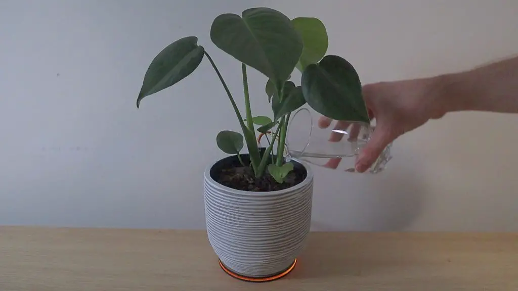
Give your plant some water:
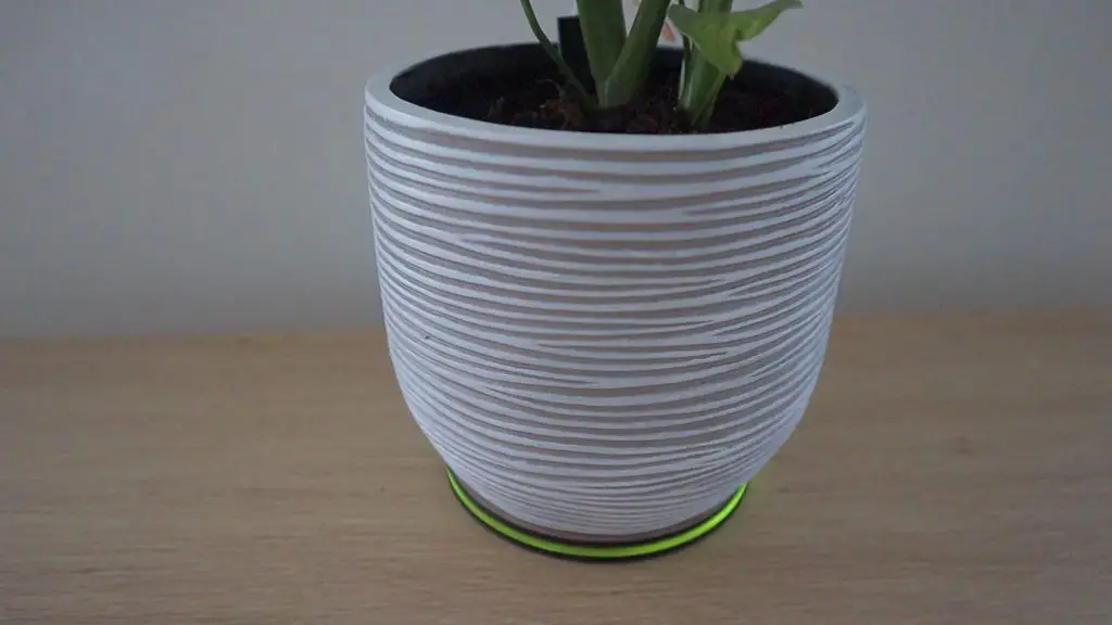
After a minute or so, the water should be absorbed into the soil and the sensor base should indicate that the plant has been watered:
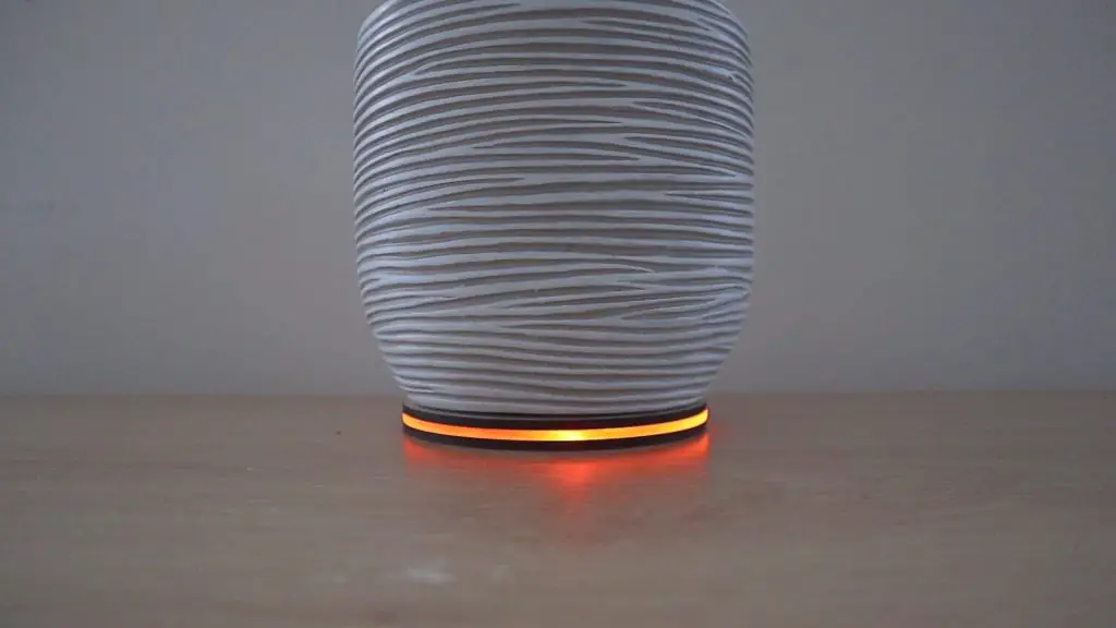
The base after a day or two when the water is drying up:
If you’re going to use yours in a really sunny room then you’ll probably want to add two or three LEDs and possibly another layer of acrylic to brighten the display a bit. Else you’ll only be reminded to water your plant at night.
Let me know what you think of this smart indoor plant base in the comments section. Are you going to try building one?
Share This Guide
Hey Michael.
I really like this. I received my XAIO a couple days back and started looking for projects, yours instantly caught my eye, so I’m going to make one with a view to later add a couple extra LED’s. I’ve ordered everything I need to complete the project and wired everything up.
I have a question regarding clibration – I’ve added “Serial.begin(9600);” to ‘void setup’, and “Serial.println(analogRead(moisturePin));” to ‘void loop’, and started the serial monitor, but I’m getting single value results every couple of seconds;
14:05:11.701 -> 3
14:05:13.713 -> 3
14:05:15.725 -> 3
14:05:17.690 -> 3
14:05:19.697 -> 4
14:05:21.706 -> 3
14:05:23.717 -> 3
14:05:25.684 -> 3
I’ve noticed that when you defined ‘wetCal’ and ‘dryCal’, you’ve used 750 and 1023 respectively – Am I missing something? I’ve looked through the code but I’m relatively new to Ardunio, so not entirely sure where the numbers become truncated, if at all – I am however willing and able to learn!
TIA for your help, and thanks for this amazing project!
Hi Mike,
That’s great, good luck with your build! I definitely think it’s worth adding a couple of extra LEDs to make the light a bit brighter.
That seems like you aren’t getting any signal back from the sensor, 3 is pretty close to 0V on the analog input. These sensors work in reverse, so dry will give you a higher reading than wet on the input, that’s what those two numbers refer to. If the sensor is out of water or soil (in air) then you should get something similar to 1023 on the serial monitor and when it is in water then you’ll get something a bit less than my wet value, probably around 650.
It’s possible that your sensor isn’t switching on. I’ve found that a few of the cheaper versions of these sensors claim that they work on 3.3V, but they actually require a slightly higher voltage. How is yours powered? Try powering it using the GND and Vin pins, this should supply it with 5V from the USB input rather than the 3.3V from the Xaio which may get it working. It will still only output 3.3V maximum as it steps the voltage down in any case, so you won’t damage your Xaio (in theory, you might want to check this with a multimeter first).
Thanks for your prompt response!
This makes sense, I checked and I’m getting 4.38v on the return leg of the sensor (Yellow/Pin 9), I’m glad you mentioned testing and I didn’t actually connect it up :o) I have 5 of these sensors since it was cheaper to buy 5 [£8.99 on Amazon UK], so with this information at the fore, I shall henceforth and see what I can do to make it work. Knowing that the readings are inverted is half the battle.
My breadboard is super cheap and I’m not convinced that I’m getting continunity half the time either, so I’ll start by soldering directly to the XAIO to give me half a chance.
I saw a video on YouTube [v=QGCrtXf8YSs] that details bridging SIG/GND, and another video on how to make it 3.3v compliant [v=Odtz8g5A-bA]. It would be great to hear your thoughts on those!?
I’ll post back whatever I turn up. Thanks again!
Yeah that’s not right, it may be slightly over 3.3V if you’re supplying 5V, but definitely not as high as 4.4V. Soldered connections are definitely better for these circuits, can you solder a plug into it so that you can swap the sensors over if need be? I doubt the bridge would help in your case (unless yours is dead), I’d try out the regulator removal one on one sensor and see what happens. I assume that the onboard regulator drops the 3.3V below a level that the onboard chip can operate (despite being sold as 3.3V compatible), so removing it would fix this problem and the other connections are just to reroute the raw supply onto the chip. Let me know how it goes!
Hi Michael ,
just look at your idea, and want try it , so i’ll buy some part as i have some already for the base i’ll design it and will print .
At now i just have 1 question abt the power as there is no battery in your project i presume it connected into a USB plug for phone or any usb power ?
I pick up the code and seems ok i’ll see further for the set up according my plant .
I need to understand more and learn too , i can design what i want but beginner in program and electronic ,
nice job and thx for your time
Hi Patrick,
That’s great. It’s all powered using the USB C port on the back of the Seeeduino Xiao. I just plugged this into a USB power supply, a power bank would work as well.
Yeah just work through it and you should learn quite a lot along the way. This is a fairly simple project for beginners.
Thank you!
Hey Michael ,
Thanks for you quick reply ,well i’ll certainly come back to you as am not sure to get ”the start by defining the IO pin numbers and the calibration limits” .
i’ll built all 1st then let’s see , for now i just wondering me if there would be a solution to avoid the USB power ? If i replace it with battery button like the CR1620 Lithium 3V it’s cheap to get the support for this kind of battery and people can out their plant where ever they like and not close from a electric plug !
what do you think or propose ?
thx again
Hi Michael , thanks for share the project! I’m trying to do my own right now.
I don’t have the Seeeduino Xiao microcontroller but I have an Arduino Nano 168p 3.0 Micro Usb but I’m not an expert with this kind of things. Can I use the Arduino Nano for this project? Could you help me with the kind of pins that I need for each connection?
Thanks,
David
Hi David,
Yes you could easily use an Arduino Nano instead of the Seeeduino Xiao. You just need to use one analogue input (try A0) for the moisture sensor and two digital PWM outputs (try D5 and D6) for the LED.