Elegoo is one of the popular names in the Arduino starter kit spaces, making great value starter kits with a good instruction set to get you started tinkering with Arduinos and electronics. They sent me their Uno project super starter kit to try out and share with you. So, I’ll be doing just that and sharing two small projects which I built using the kit as well.
The kits are available through their Amazon storefronts in a number of different countries.
Elegoo Uno Project Super Starter Kit – Buy Here
You can watch my video of the unboxing and projects here, or read on for the write-up.
Unboxing The Elegoo Uno Project Super Starter Kit
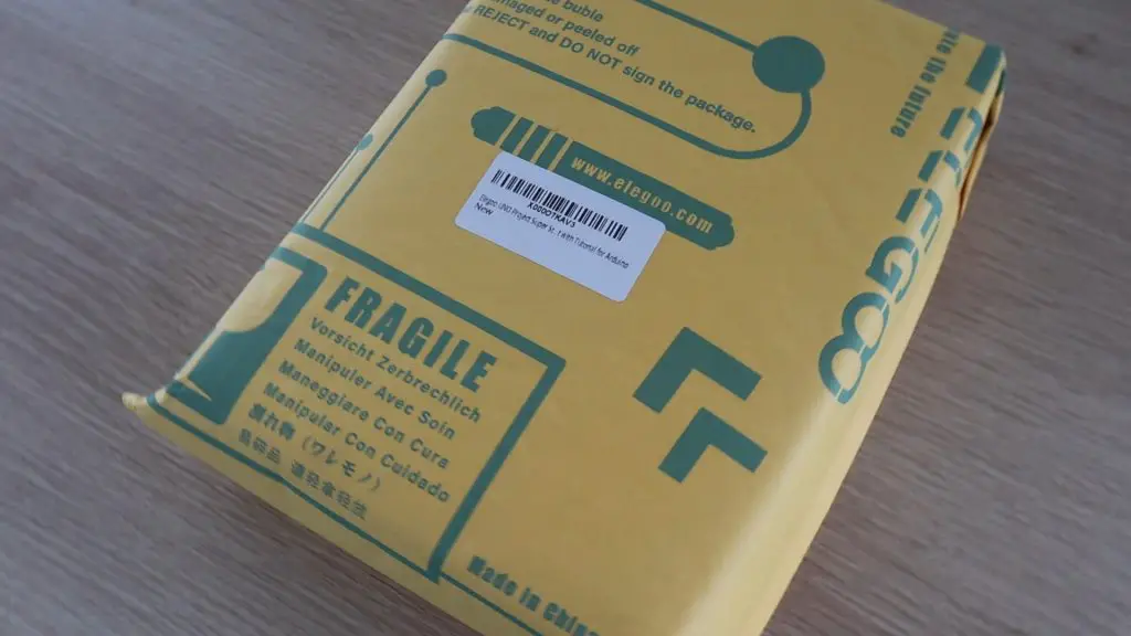
As expected from Amazon, the kit arrived really quickly and was well packaged and protected. The kit arrived in the usual bubble-sleeve Amazon-branded package and inside it was this yellow package, which Elegoo themselves have wrapped up as well.
Inside this yellow package, the kit is packaged into a plastic storage case, which is great for keeping all your components together after you’ve started using them.
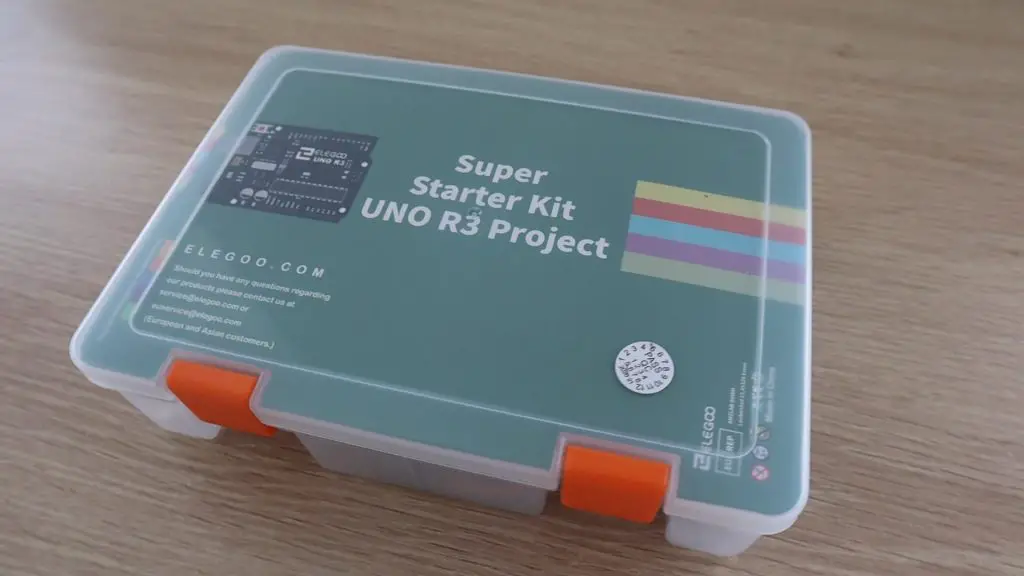
The super starter kit case is pretty tightly packed when you get it, but once you’ve removed the plastic packaging and foam pieces for shipping, you shouldn’t have a problem getting the components back into the box again once you’re done with a project.
Included with the kit is a CD which contains a detailed tutorial guide as well as the code or sketches and the libraries used in the tutorials. We’ll have a look at this in more detail later on.
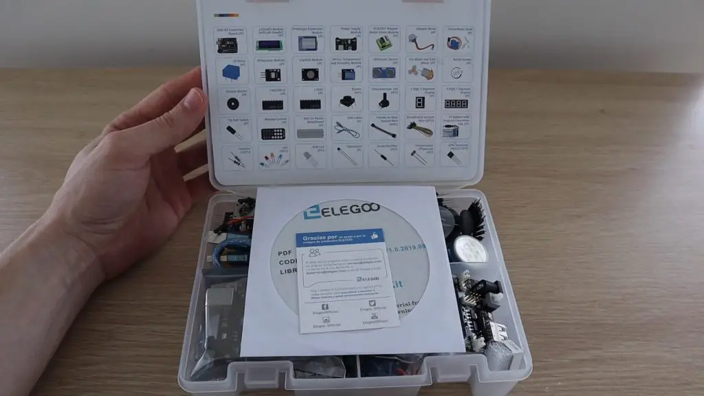
Let’s get the kit unpacked and see what’s included.
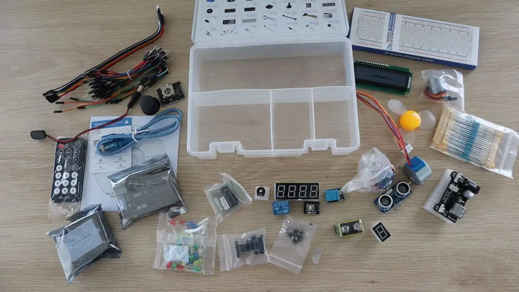
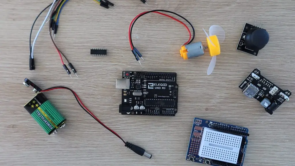
You’ve got a pretty good range of electronic components to get started with, here is what’s included in the Elegoo Uno Project Super Starter Kit:
- 1pcs Elegoo Uno R3 Controller Board (Arduino-Compatible)
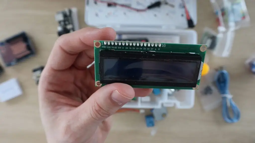
- 1pcs LCD1602 Module
- 1pcs Prototype Shield With Mini Breadboard
- 1pcs Power Supply Module
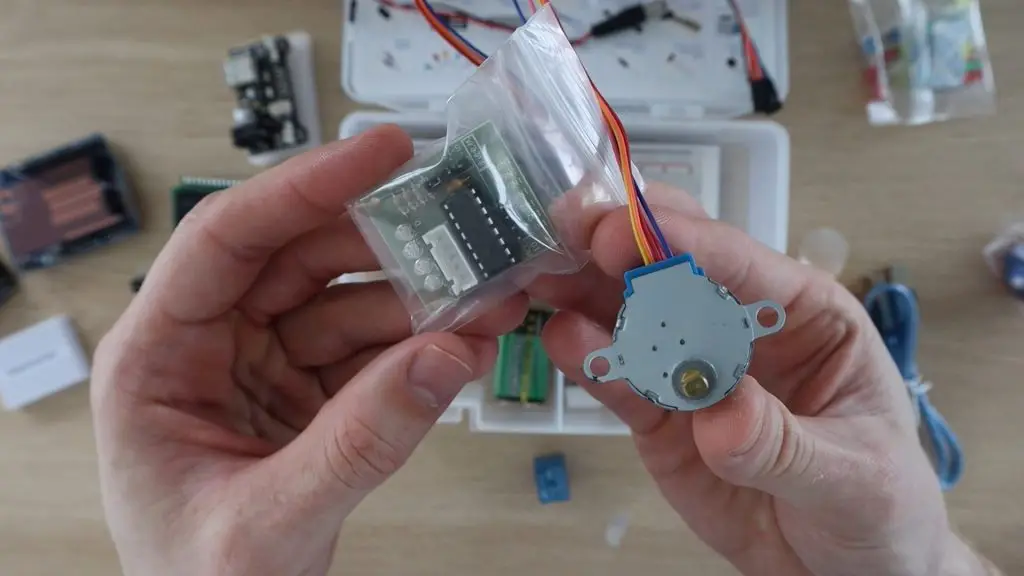
- 1pcs ULN2003 Stepper Motor Driver
- 1pcs Stepper Motor
- 1pcs Servo Motor (SG90)
- 1pcs 5V Relay
- 1pcs IR Receiver
- 1pcs Joystick Module
- 1pcs DHT11 Temperature and Humidity Module
- 1pcs Ultrasonic Sensor
- 1pcs DC Motor and Fan
- 1pcs Active Buzzer
- 1pcs Passive Buzzer
- 1pcs IC 74HC595
- 1pcs IC L293D
- 5pcs Push Button
- 1pcs Potentiometer
- 1pcs 1 digit 7-segment Display
- 1pcs 4 digit 7-segment Display
- 1pcs Tilt Switch
- 1pcs IR Remote
- 1pcs Breadboard
- 1pcs USB Cable
- 10pcs Female-to-male DuPont Wire
- 65pcs Breadboard Jumpers
- 1pcs 9V Battery
- 30pcs Various Resistors
- 5pcs Yellow LED
- 5pcs Blue LED
- 5pcs Green LED
- 5pcs Red LED
- 5pcs White LED
- 2pcs RGB LED
- 1pcs Thermistor
- 2pcs Diode Rectifier (1N4007)
- 2pcs Photoresistor
- 2pcs NPN Transistor (PN2222)
As with any starter kits, there are probably components that you’re interested in and some which you may never use, but you really can’t beat the value you get with a kit like this. You’d easily pay two to three times what this kit costs if you try and buy the components separately, so it’s a great way to start out.
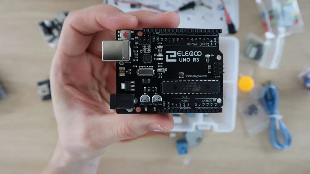
The Arduino you get with this kit is Elegoo’s copy of the Uno. It’s a great starter board, compatible with a wide range of shields and accessories, and is probably one of the most widely used as well. So you shouldn’t have any trouble trying out different projects and new sensors once you’ve worked through their tutorials.
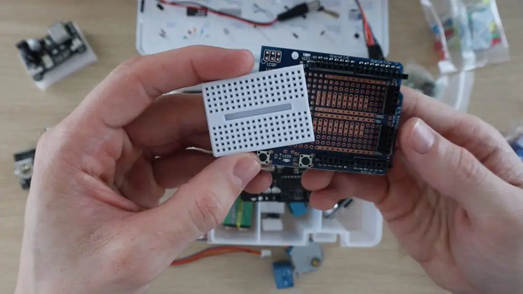
They’ve included both a full-sized breadboard along with a prototype expansion shield with a mini breadboard on the top so that you can build more compact projects as well.
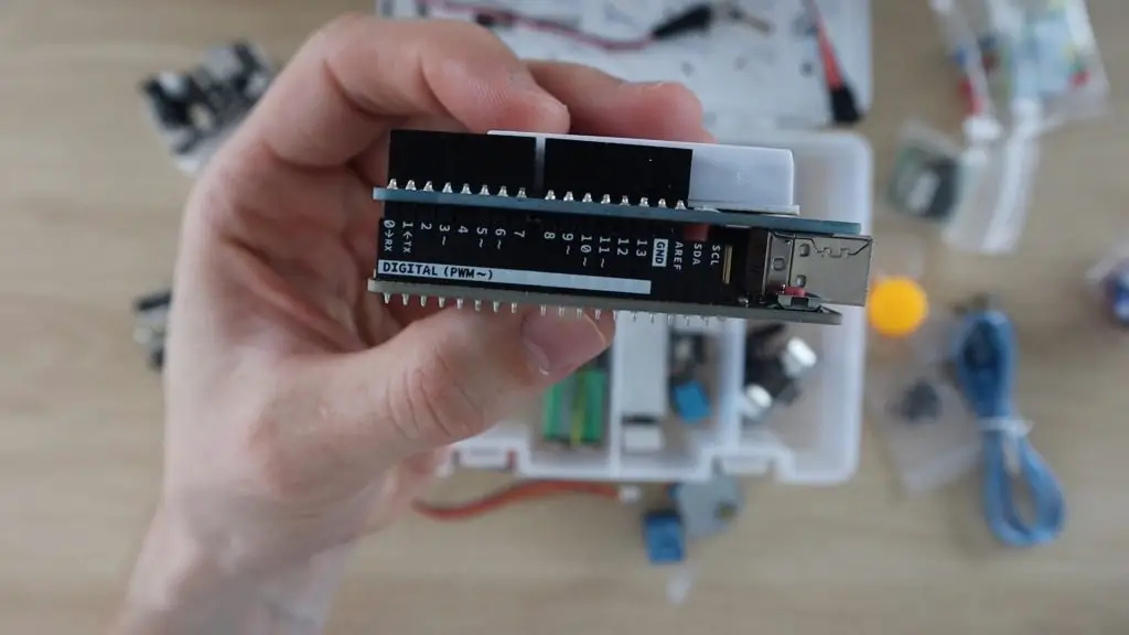
I do like that they’ve labelled the sides of the header pin strips with the port numbers. This is really useful if you’ve got a shield plugged in or you can’t see the top of the Arduino because it’s tucked into a tight case or container for a project.
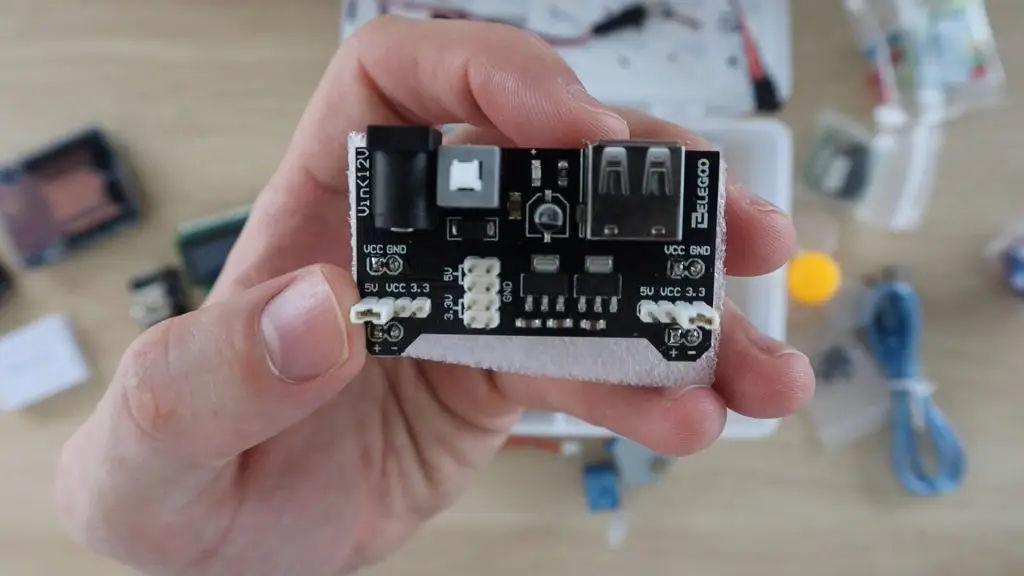
Some other nice inclusions are a dedicated breadboard power supply with a 5V and 3.3V regulator, an LCD display and a stepper motor and driver.
Tutorial Guide & Included Code
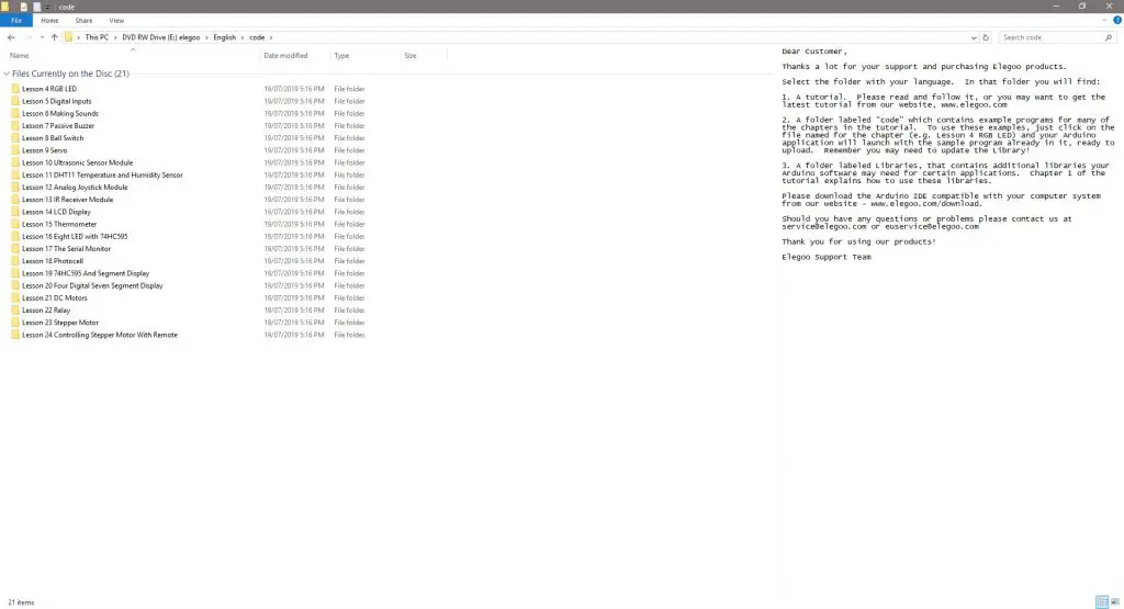
Now let’s have a look at what is included on the CD with the Elegoo Uno Project Super Starter Kit.
As mentioned before, the CD contains a detailed tutorial guide as well as the code or sketches and the libraries used in the tutorials in a number of different languages.
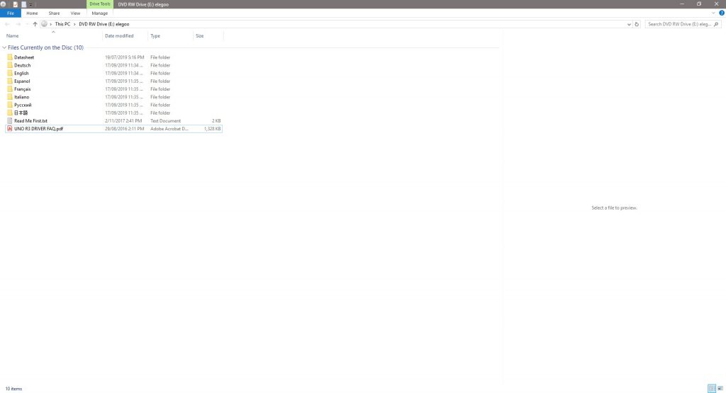
This is quite useful as a few kits I’ve seen leave it up to you to find the libraries they’ve used, which can be a problem for new users. You can also download the contents of the CD along with up to date libraries through the Elegoo website, the download is around 250MB.
The tutorial guide starts out by explaining the Arduino IDE as well as how to connect and program your Arduino and how to install the included libraries.
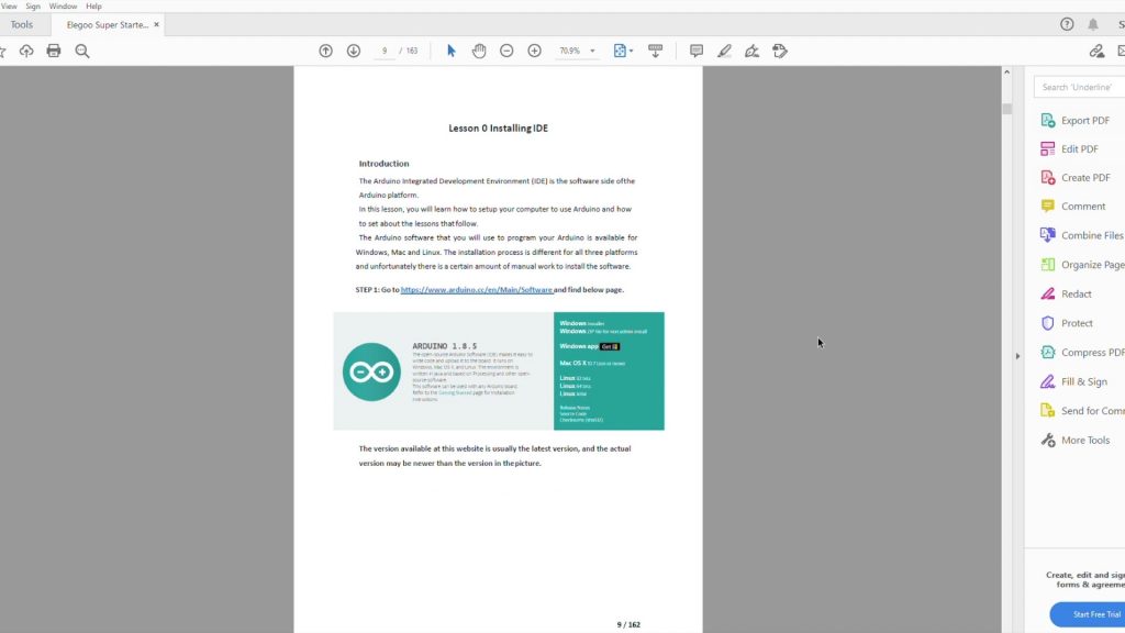
They also detail how to install the drivers for the board. Both my Windows PC and mac picked the board up as an Arduino Uno right away and I didn’t need to install any additional drivers.
You’re then guided through 24 Lessons in total, which show you how to connect and program the Arduino to use all of the components supplied in the kit. Once you’ve worked through all of these, you should have a really good understanding of how any Arduino works and you’ll be able to build some pretty cool projects.
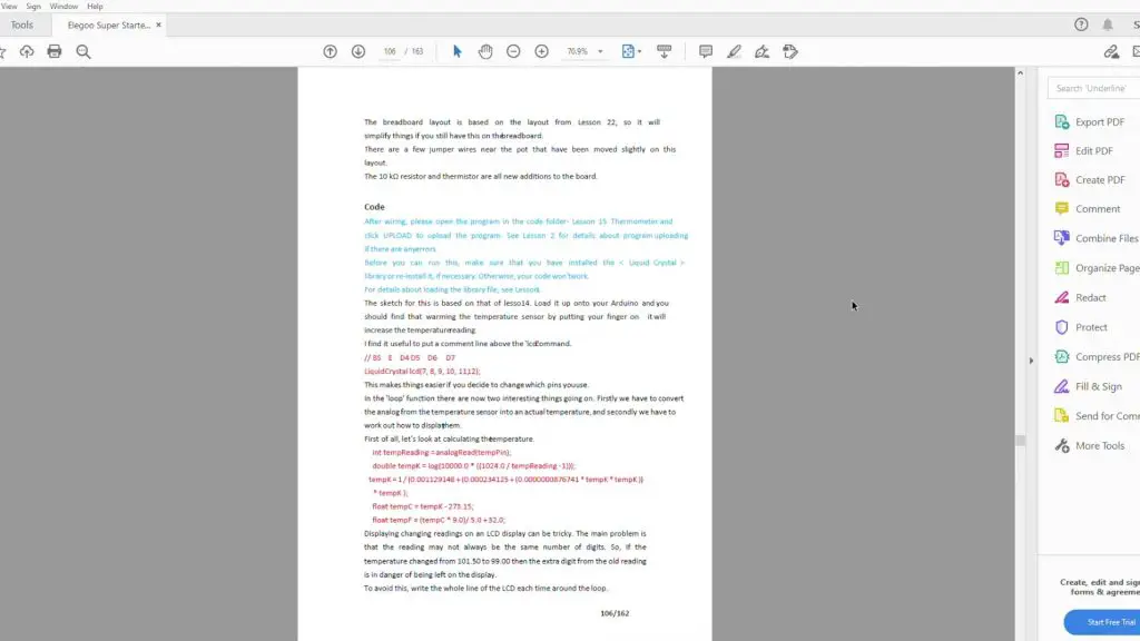
The lessons are quite details and tell you exactly what you need and how to connect them. They also give you a bit of background information for the components and give you a photograph of what the final setup should look like. You shouldn’t have any trouble getting each lesson up and running using the included components and the included sketches.
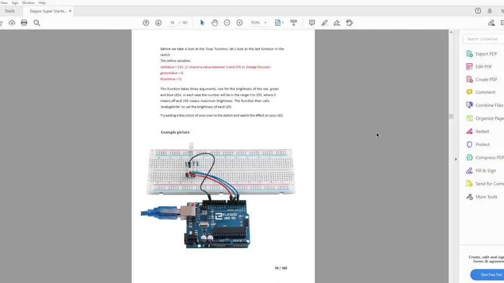
The only issue I could point out with the lessons is that they don’t go into much detail on how the code works. Some lessons have more details than others and they do point out any areas which you may get stuck or need to change for your specific project, but you probably won’t learn too much about the code if you don’t already have a basic understanding of the Arduino programming language or C++. But there is enough information to help you get by and get through each of the lessons.
Rather than go through one of the lessons which have already been done, I’ve put together two basic projects which use the included components and just combine sections of the included example code to make, so are really easy to get running.
Sample Project 1 – DC Motor Throttle
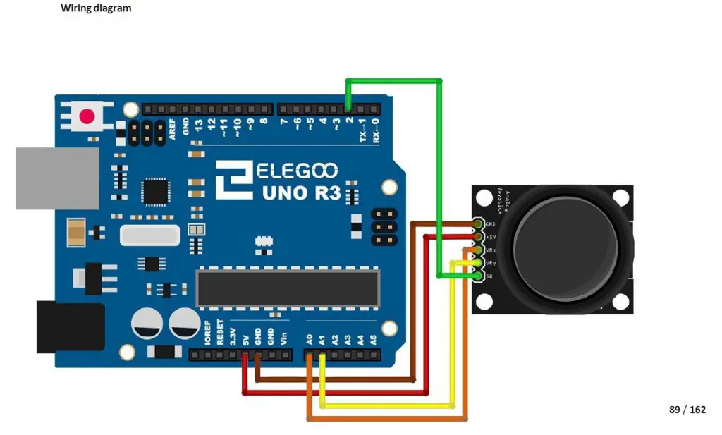
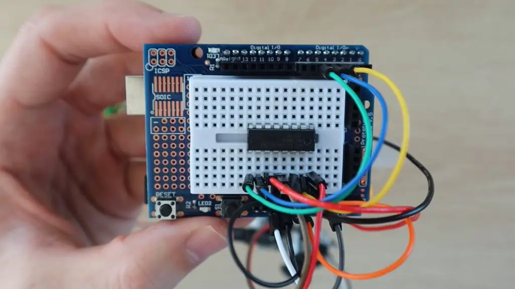
The first project I tried with the super starter kit is a simple throttle for the DC motor and fan. It uses one axis of the joystick to control the speed and direction of the motor using the included L293D motor driver chip. This project uses Lesson 12 for the analog joystick module input and Lesson 21 for the DC motor and driver. I assembled the components onto the prototyping shield and mini breadboard.
For this project, you’ll need:
- Elegoo Uno R3
- Prototyping Shield & Mini Breadboard
- 9V Battery & Lead
- L293D Motor Driver
- DC Motor & Fan
- Joystick Module
- Power Supply Module
- Jumpers
I’ve connected the motor and driver as well as the analog joystick to the Arduino as outlined in the two Lessons in the tutorial.
For the joystick, we’ll only need one axis, I used the one to A1:
For the L293D DC Motor driver, I’ve used the circuit as shown, but with the mini breadboard. The power connections will need to be made directly onto the 5V header pins on the power supply module.
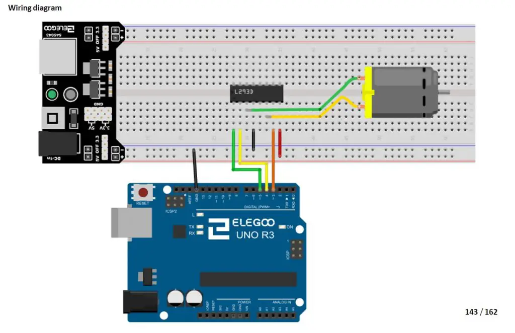
Once you’ve made the connections, your breadboard should look like this:
You’ll then need to program your Arduino.
I’ve also just copied sections of code from both lessons to make a really simple sketch to drive the motor.
//DC Motor Throttle Example Project

#define ENABLE 5                    //Define the motor driver pins
#define DIRA 3
#define DIRB 4

const int X_pin = A1;               //Define joystick input pin

int motSpeed = 512;                 //Variable to store the motor speed

void setup()
{
  pinMode(ENABLE,OUTPUT);           //Set the motor driver pin functions
  pinMode(DIRA,OUTPUT);
  pinMode(DIRB,OUTPUT);
}

void loop()
{
  motSpeed = analogRead(X_pin);                 //Read in the joystick position
  if (motSpeed>=532)
  {
    motSpeed = map(motSpeed,532,1023,0,255);    //Map the motor speed to the driver range
    analogWrite(ENABLE,motSpeed);               //Set motor speed
    digitalWrite(DIRA,HIGH);                    //Set motor direction
    digitalWrite(DIRB,LOW);
  }
  else if (motSpeed<=492)
  {
    motSpeed = map(motSpeed,492,0,0,255);       //Map the motor speed to the driver range
    analogWrite(ENABLE,motSpeed);               //Set motor speed
    digitalWrite(DIRA,LOW);                     //Set motor direction
    digitalWrite(DIRB,HIGH);
  }
}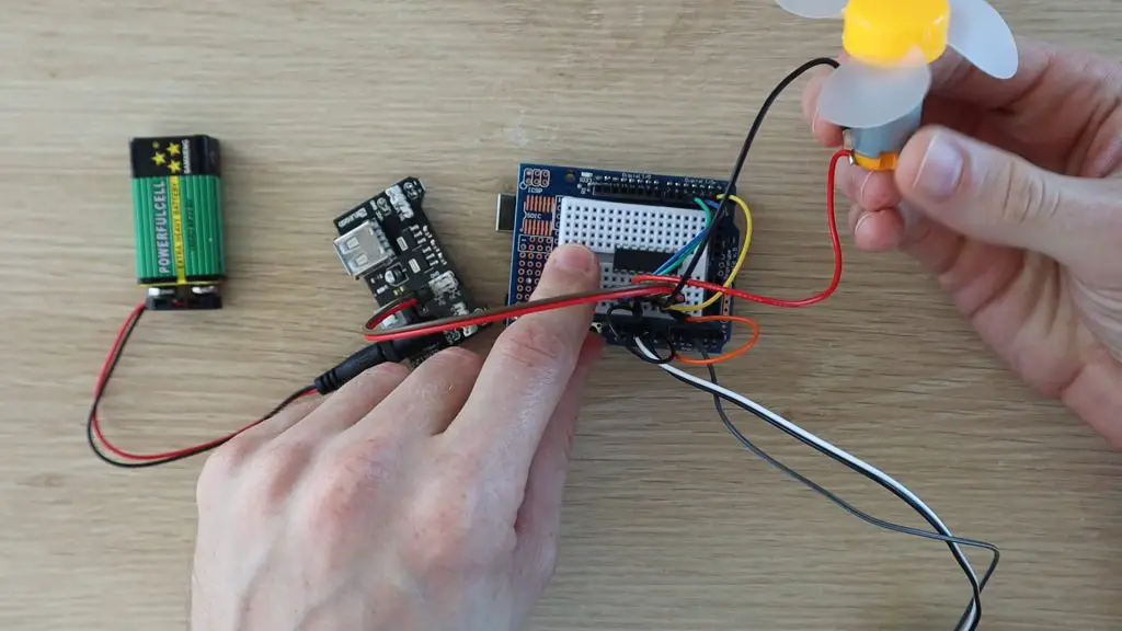
I found the included battery to be a bit sluggish, for the motor, so I replaced it with a power supply to give it a bit more speed.
Push the joystick forward to drive the fan in one direction and backwards to reverse the fan.
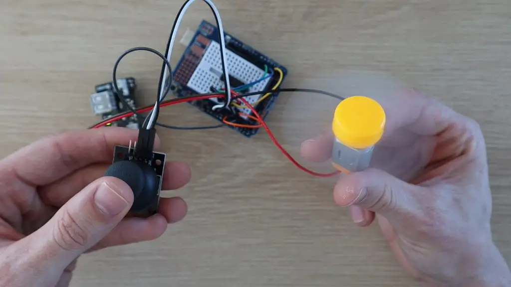
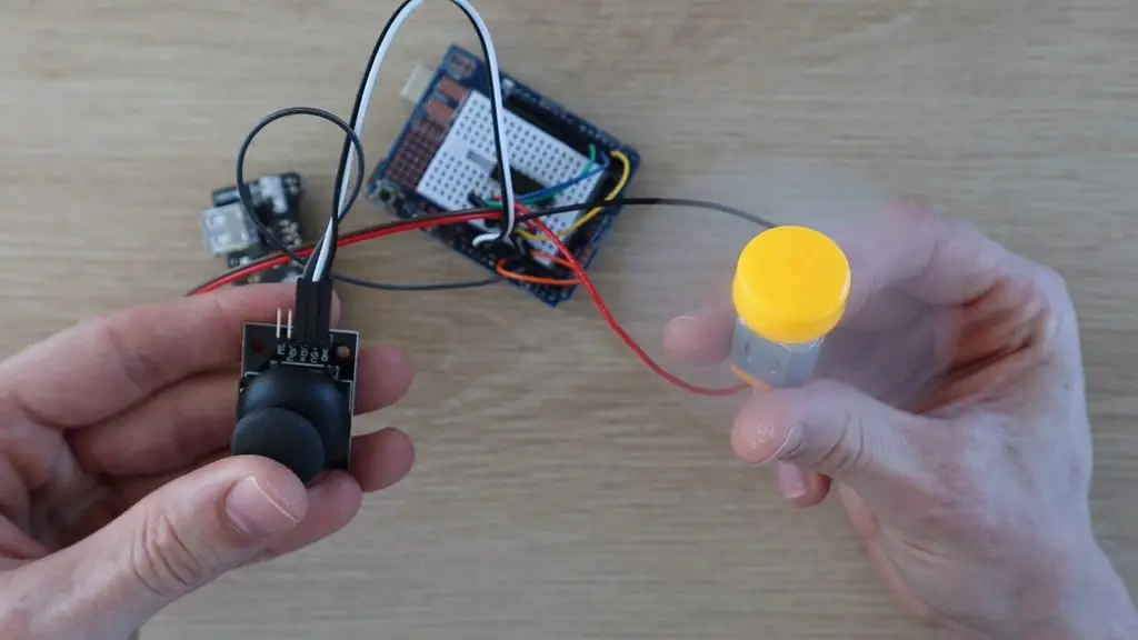
The fan’s speed is also proportional to how far the joystick is pushed, so you can slow it down or speed it up in either direction. Have a look at the video at the beginning of this review to see some clips of the motor running.
Sample Project 2 – Parking Assistant
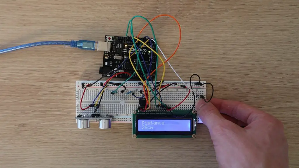
The next project is a bit more complex, but all of the components and lessons used are included with the Elegoo Uno Project Super Starter Kit. It’s a parking assistant, which can be mounted onto a wall in front of your parking bay or garage to indicate when your car is in the right spot.
This parking assistant measures the distance to your car and guides you to park it in the correct spot using an LCD display readout and an LED, which progressively changes from green to red. The red LED starts flashing if you get too close. A button on the assistant lets you set a new parking position as well.
For this project, you’ll need:
- Elegoo Uno R3
- Breadboard & Jumpers
- Ultrasonic Sensor
- LCD Display
- Tactile Pushbutton
- 5mm RGB LED
- 2 x 200ohm Resistors
- 10K Potentiometer
This project uses the following lessons from the tutorial:
- Lesson 4 – RGB LED
- Lesson 5 – Digital Inputs
- Lesson 10 – Ultrasonic Sensor Module
- Lesson 14 – LCD Display
I’ve kept the connections for the LCD display the same as in the tutorial. The other components have been adjusted for the available IO.
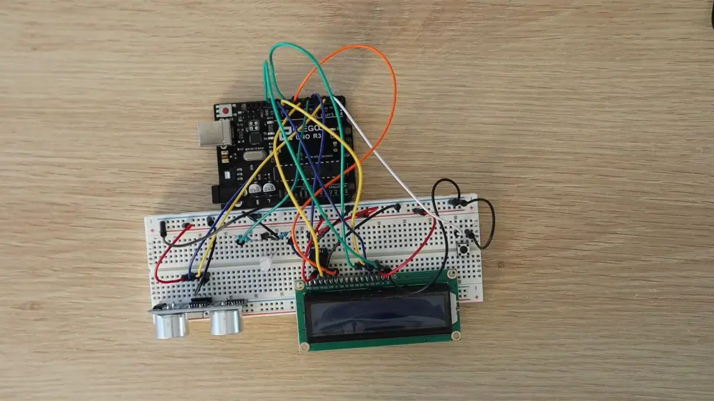
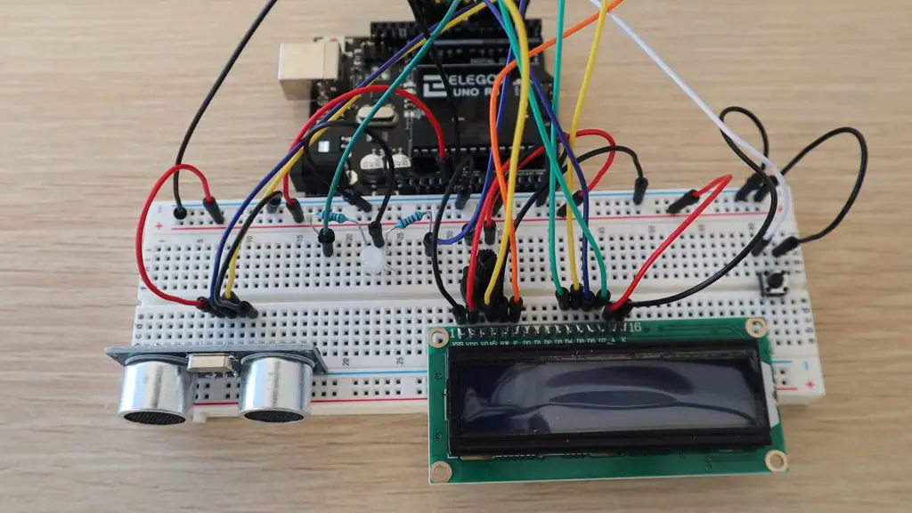
Start off by plugging your components into your breadboard. Try to separate them as much as possible, so that you’ve got lots of space to connect your jumpers.
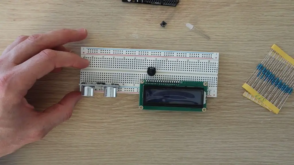
There are three components which you should position in certain places to avoid additional jumpers:
- Plug a 220ohm resistor onto a track connected to each of the positive (anode) legs of the LED. You’ll only need the red and green legs, you can leave the blue leg disconnected.
- Plug the wiper (center leg) of the pot onto the same track as V0 on the LCD. This pot will be used to adjust the contrast of the LCD.
I’ve tried to keep this project as close to the example lessons in the Elegoo kit as possible so that it’s pretty easy to use the same connection diagrams and just copy and paste parts of the code to get it working.
Start off by connecting power to the components as shown in the below image, or follow the connections outlined in the lessons. You need a GND and 5V supply to the ultrasonic sensor, GND to the LED, GND to the pushbutton, and then a number of GND and 5V connections to the LCD and pot.
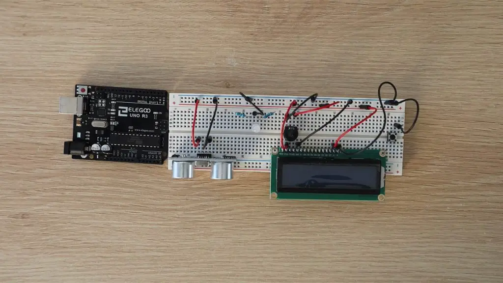
The connections to the LCD are done as per Lesson 14:
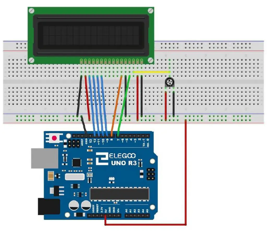
Once this is done, you can connect the remaining components to your Arduino’s IO:
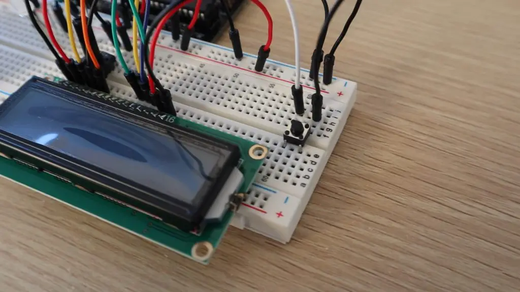
- Pushbutton – D2
- Ultraonic Sensor Echo – D3
- Ultrasonic Sensor Trigger – D4
- RGB LED Green Leg – D5
- RGB LED Red Leg – D6
- LCD RS – D7
- LCD EN – D8
- LCD D4 – D9
- LCD D5 – D10
- LCD D6 – D11
- LCD D7 – D12
Once you’ve made all of the connections, you can upload the sketch to your Arduino. This sketch has also been mostly constructed from parts of the four lessons, so it should be fairly easy to follow:
//Parking Assistant Example Project

#include "SR04.h"                             //Import Ultrasonic Sensor Library
#include <LiquidCrystal.h>                    //Import LCD Library

#define TRIG_PIN 4                            //Define sensor pins
#define ECHO_PIN 3

SR04 sr04 = SR04(ECHO_PIN,TRIG_PIN);          //Create sensor object
LiquidCrystal lcd(7, 8, 9, 10, 11, 12);       //Create LCD object

int greenLedPin = 5;                          //Define IO pins
int redLedPin = 6;
int buttonPin = 2;

int maxDist = 80;                             //Define parking assistant parameters
long dist;
long parkDist = 20;

void setup()
{
  lcd.begin(16, 2);                           //Start the display and display startup text
  lcd.print("Parking");
  lcd.setCursor(0,1);
  lcd.print("Assistant");
  pinMode(greenLedPin, OUTPUT);               //Define IO pin functions
  pinMode(redLedPin, OUTPUT);
  pinMode(buttonPin, INPUT_PULLUP);
  delay(2000);
  lcd.clear();                                //Clear the startup text
}

void loop()
{
  boolean tooClose = false;
  dist = sr04.Distance();                                       //Measure the distance to an object
  lcd.print("Distance");                                        //Display the measurement
  lcd.setCursor(0,1);
  lcd.print(dist);
  lcd.print("cm");
  if(dist >= maxDist)                                           //Define the parking distance limits for the LED
    dist = maxDist;
  else if(dist <= parkDist)
  {
    dist = parkDist;
    tooClose = true;
  }
  analogWrite(greenLedPin, map(dist,parkDist,maxDist,0,255));   //Display the object distance on the RGB LED
  analogWrite(redLedPin, map(dist,parkDist,maxDist,255,0));
  if (tooClose)
  {
    digitalWrite(redLedPin, HIGH);
    delay(250);
    digitalWrite(redLedPin, LOW);
    delay(250);
  }
  if (digitalRead(buttonPin) == LOW)                            //Set the new parking distance if the button is pushed
  {
    parkDist = dist;
    digitalWrite(greenLedPin, HIGH);                            //Flash LED to indicate new distance has been set
    delay(500);
    digitalWrite(greenLedPin, LOW);
    digitalWrite(redLedPin, HIGH);
    delay(500);
    digitalWrite(redLedPin, LOW);
  }
  delay(500);
  lcd.clear();                                                  //Clear the display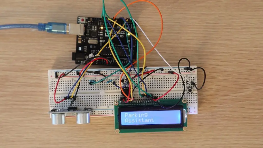
}When you power the parking assistant up, it shows a brief Parking Assistant splash screen and then starts taking distance measurements to the object in front of the ultrasonic sensor, to a maximum of 80cm – this can be changed in the code to suit your parking spot/garage.
The distance is displayed on the LCD and the RGB LED will light up according to the distance to the object. If the object is at the maximum distance, the LED will be completely green and if it is at the minimum distance (the correct parking spot) then it will be completely red.
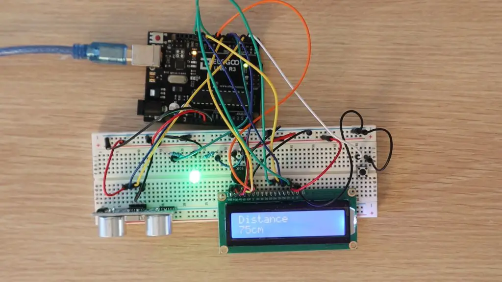
The LED will change colour proportionally in between these two limits, with a yellow colour in the middle. If the object comes closer than the minimum distance, the LED will flash red.
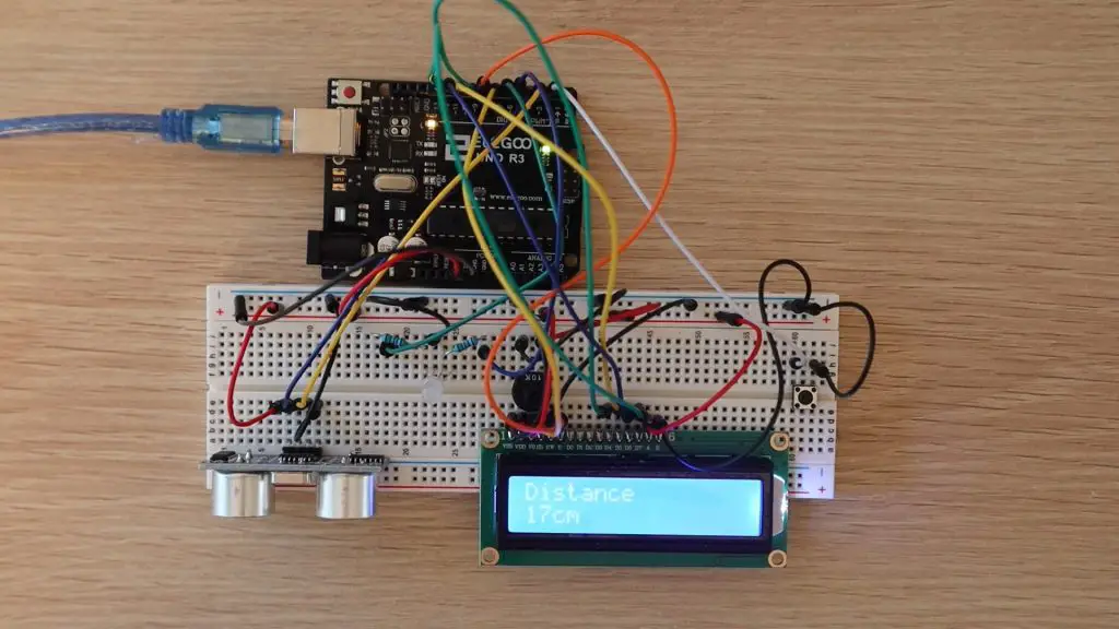
The LCD will continue to display the actual measured distance while the LED is flashing.
Trying moving your body or hand in front of the ultrasonic sensor and check that the measurements on the LCD change and that the RGB LED changes from green when you’re far away to red when you’re close by. Have a look at the video at the beginning of the review to see some clips of the parking assistant in operation.
To set a new parking position, make sure that the car is parked in the new position to be set and that the display is showing the correct distance to the car, then push the button to update the parking position. Note that this doesn’t change the maximum distance, so if you need to park your car further than this distance, then you’ll need to update this in the code, this adjustment is meant to be used for fine adjustment.
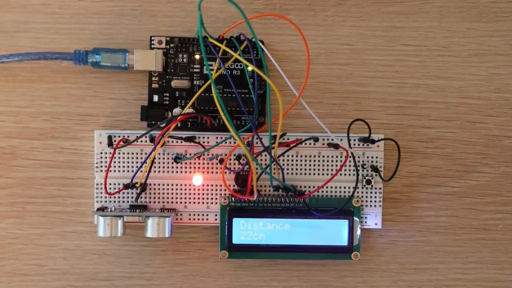
Try placing an object or your hand at a certain distance, say around 40cm from the ultrasonic sensor and push the button. The LED should flash green and then red and the new distance will then be set. You should now notice that the RGB LED turns completely red by 40cm instead of 20cm and starts flashing when the distance is less than 40cm.
To reset the distance, set the object to 20cm from the sensor and press the button again.
The correct spot being 20cm and the maximum distance being 80cm are just arbitrary numbers used for this example. You’ll need to set up your own limits for your own garage and car before you use it.
That’s it, your parking assistant can now be installed into an enclosure and mounted onto the wall in your garage. You might also want to position the LCD and LED a bit further up the wall than the ultrasonic sensor so that it’s easier to see.
Conclusion
Overall I think this is a great value kit and an excellent way to get started tinkering with Arduinos and electronics. There’s a good selection of components and unlike some other starter kits, Elegoo includes loads of jumpers, resistors and LEDs for more complex projects.
If you’re interested in buying one of these kits, head over to Amazon to pick one up. Elegoo have given me a discount code to share with you too, use the code DWZRAUL5 to get a discount on the kit from their Amazon store until 27/09/2020 11:59 PM AEST
Hello Michael,
I have something to talk with u and make u an offer, it’s gonna be pretty interesting 🙂 Could u please contact me?
josepind@yahoo.es
Hi Jose,
Sounds good, you can email admin(at)the-diy-life.com.