I bought this kit a while ago when I was looking at building an Arduino based 8x8x8 LED cube. This one was listed on Amazon as Arduino compatible, meaning that I should be able to re-program it using the Arduino IDE after assembling it to display what I want.
The kit was delivered quite quickly, but there was one pretty obvious thing missing, the assembly manual. I had a look on the product page on Amazon, emailed the supplier, and Googled the supplier and other 8x8x8 cube kits to try and find the manual. The supplier never got back to me and although I found a few similar cubes, I never found an assembly manual for this particular cube, so I packed the kit away and forgot about it for a few months.
A week ago, I found the kit again and decided to try assembling it. At worst, I’d have a cube that didn’t work and would just be a dead shelf decoration.
Here’s a video of the build and the 8x8x8 LED cube working, read on for the detailed assembly.
Buy Your Own 8x8x8 LED Cube Kit
- 8x8x8 LED Cube Kit (Like The One In The Video, Probably Has No Instructions Either) – Buy Here
- 8x8x8 LED Cube Kit (Better Quality, Not Arduino Compatible) – Buy Here
Assembling The 8x8x8 LED Cube
So let’s get started with putting the cube together.
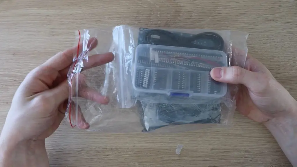
The kit arrived quite quickly and this is what was delivered.
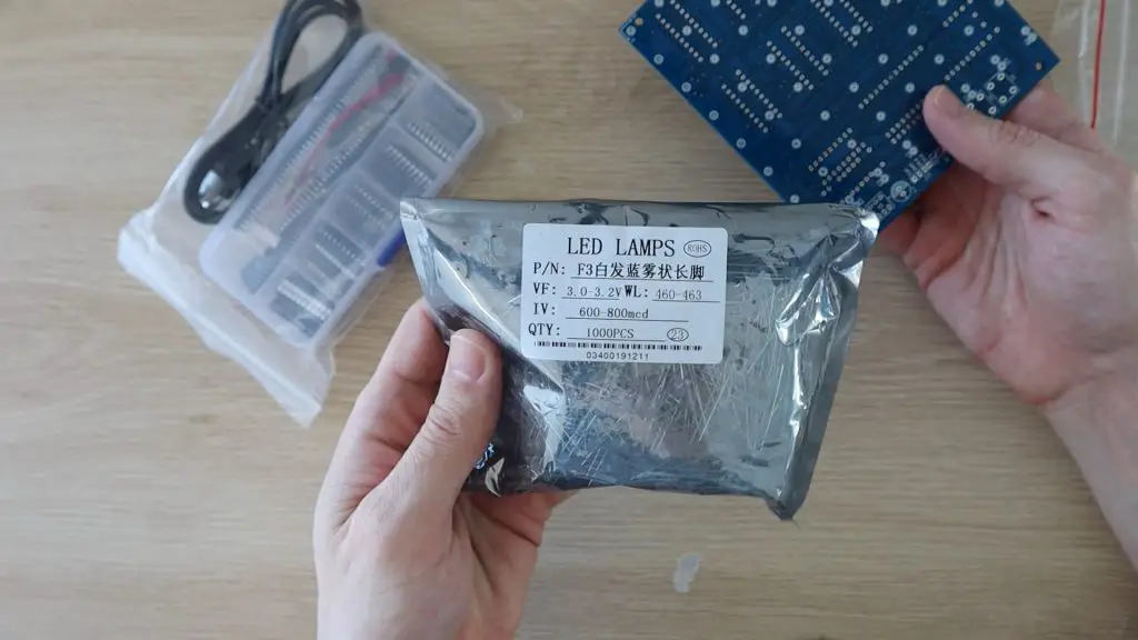
There was a bag of LEDs, they said that 550 LEDs are supplied in case some are faulty, the PCB to mount the components, and then a small case with the chips and other electronic components.
The product page said that the cube was Arduino compatible, although the chip supplied is a STC12C5A60S2 micro-controller. You’ll need a USB-2-TTL programming module to re-flash this micro-controller. There is guide a good guide and software to re-programming the STC micro-controller on GitHub.
Soldering The LED Layers
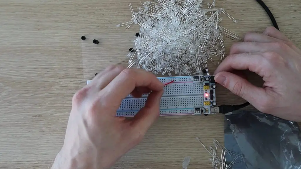
I started out by testing all of the LEDs. I’ve never found a new LED to be dead, but since they said that they included 550 LEDs in case some were faulty, I decided to test them all first to avoid have to replace LEDs once it was all assembled. I set up a simple 5V power supply and 220 ohm resistor on a breadboard and got testing.
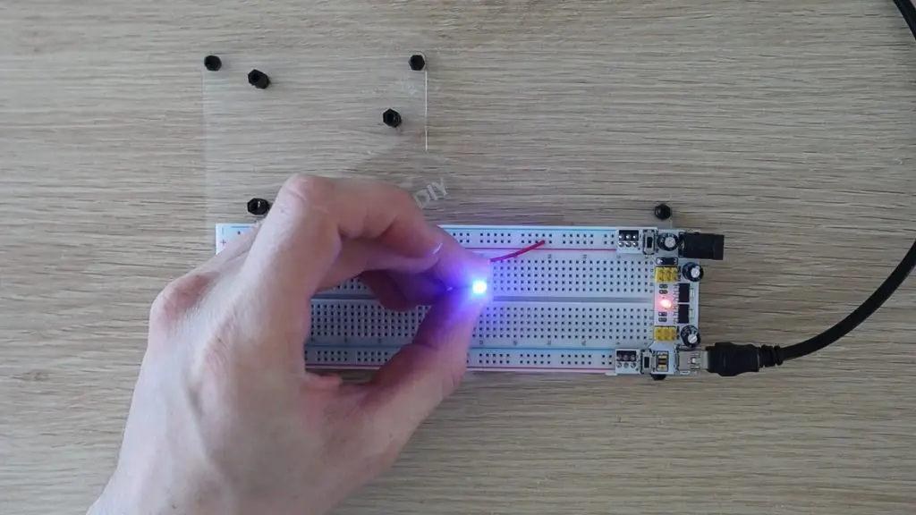
I didn’t find any faulty LEDs, but I still think it was worthwhile to save the frustration if I had.
Next, I laser cut a template to lay out the LEDs. Rather than trying to get the placing right for each individual LEDs, having an MDF board which I could press the LEDs into and then connect up while they’re held in place would dramatically speed up the process and hopefully result in nice straight and evenly spaced grids of LEDs.
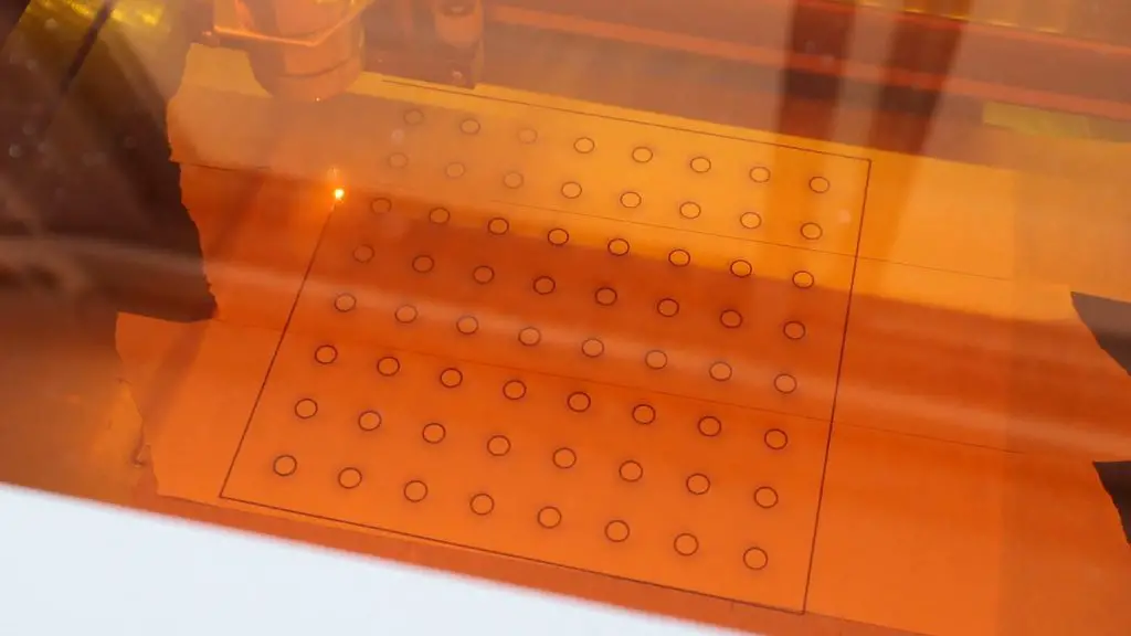
I cut two layers, one with 3mm holes to hold the LEDs and one with 5mm holes to be the bottom spacer layer so that the LEDs don’t touch the table underneath them when they’re pushed into the template.
I then layed out the 64 LEDs on the template, making sure that the LEDs were all facing the same direction.
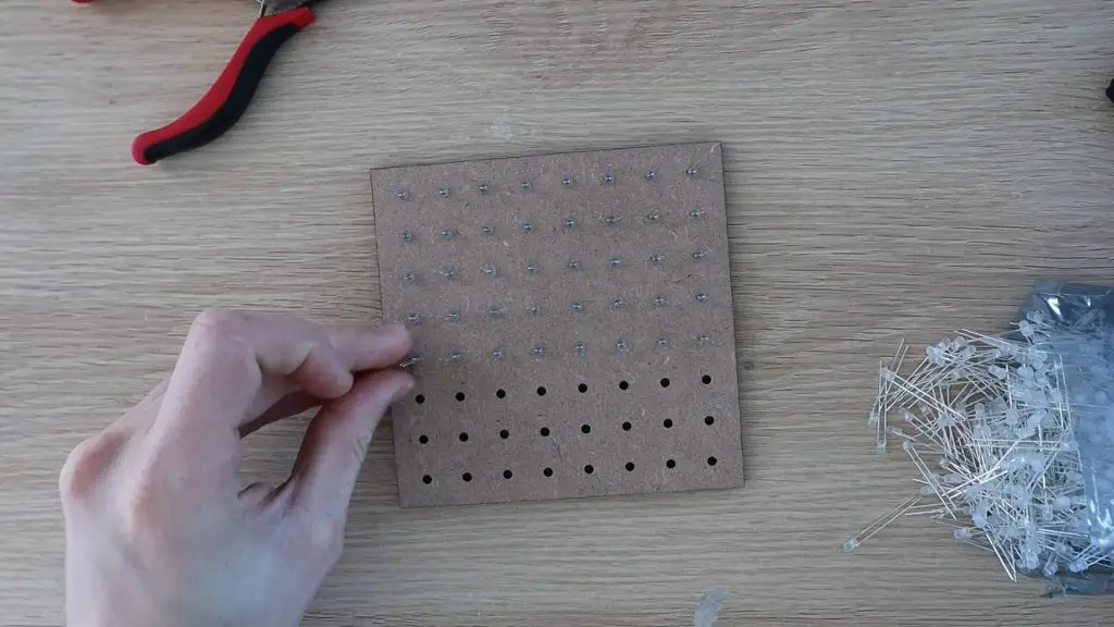
So with the longer positive leg or anode on the right side and the negative leg, or cathode on the left side.
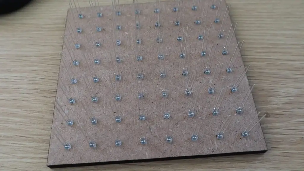
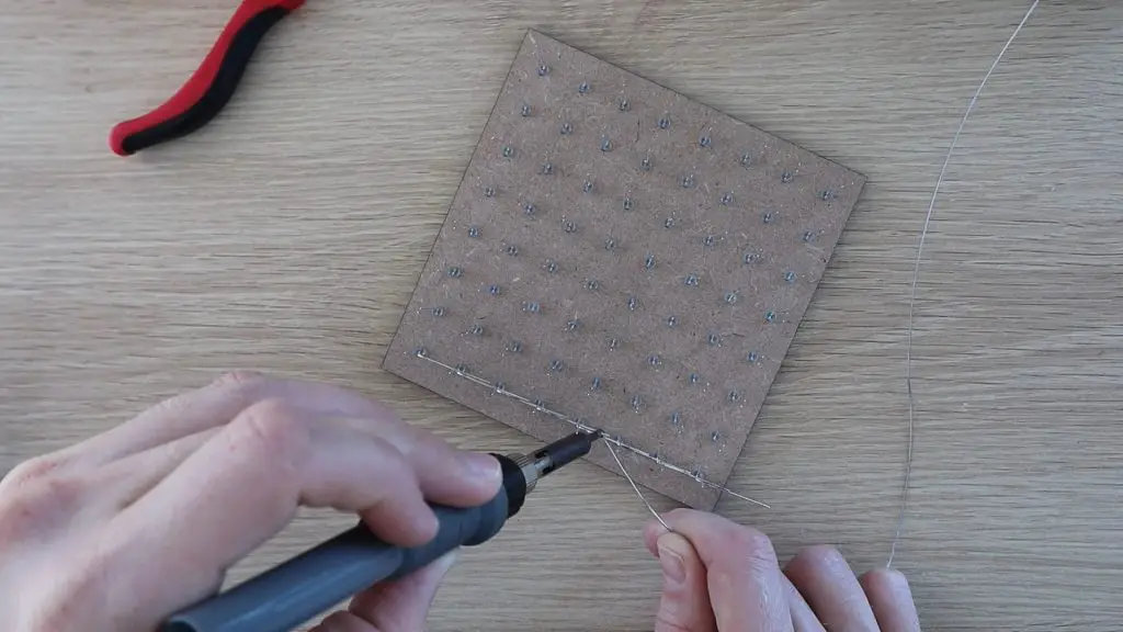
Next, the idea is to connect all of the positive legs together in each column and all of the negative legs together in each row, making sure that they don’t touch each other. I started with the negatives, bending them all down so that there was some overlap between them.
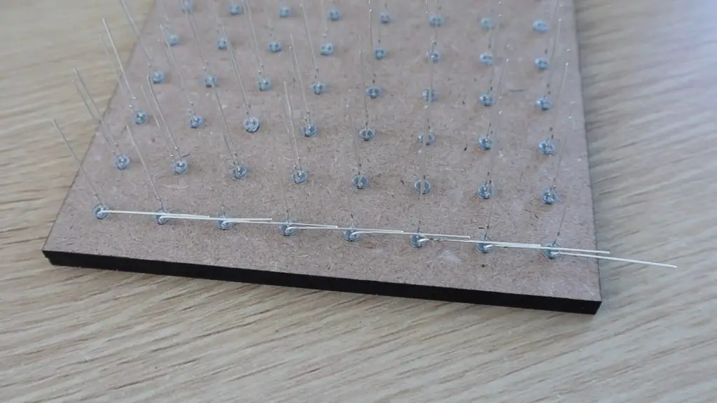
I then soldered them together.
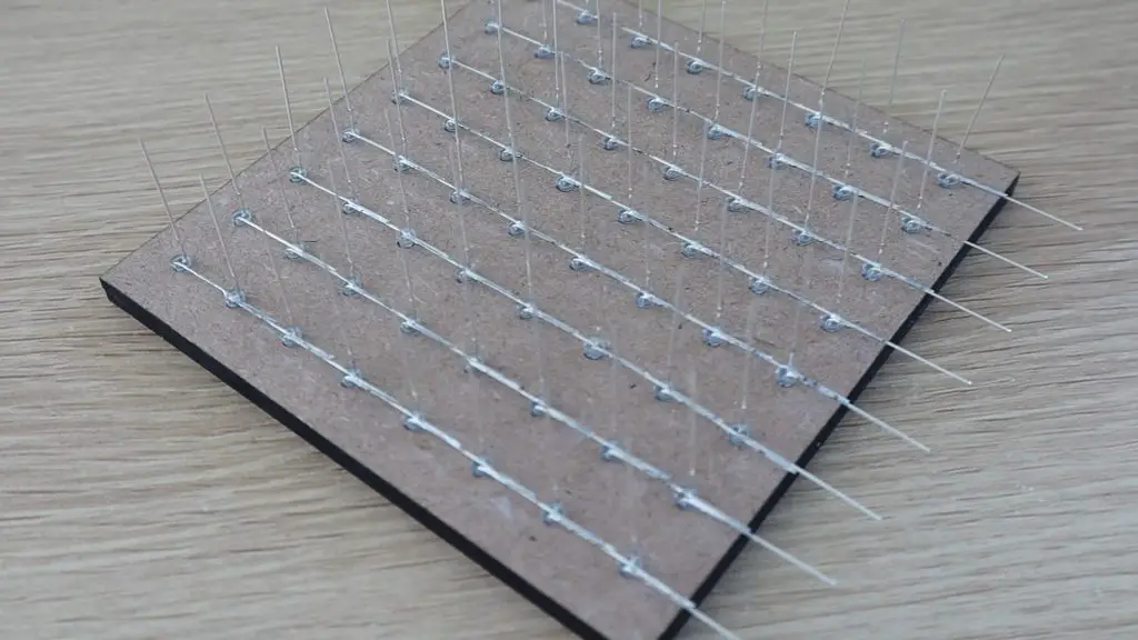
Once all of the negatives were done, I did the positives. I used a pair of pliers to space the bend a little away from the back of the LED so that the positive connections were spaced about a millimeters away from the negative connections. In hindsight, these legs should have been bent in the opposite direction in order to keep the connections on the back side of the cube when it’s on display, but this isn’t particularly noticeable in the end.
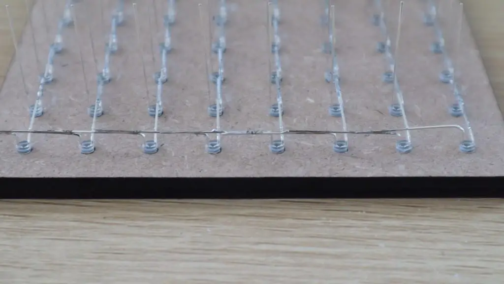
I continued this until all of the columns and rows on this layer were connected.
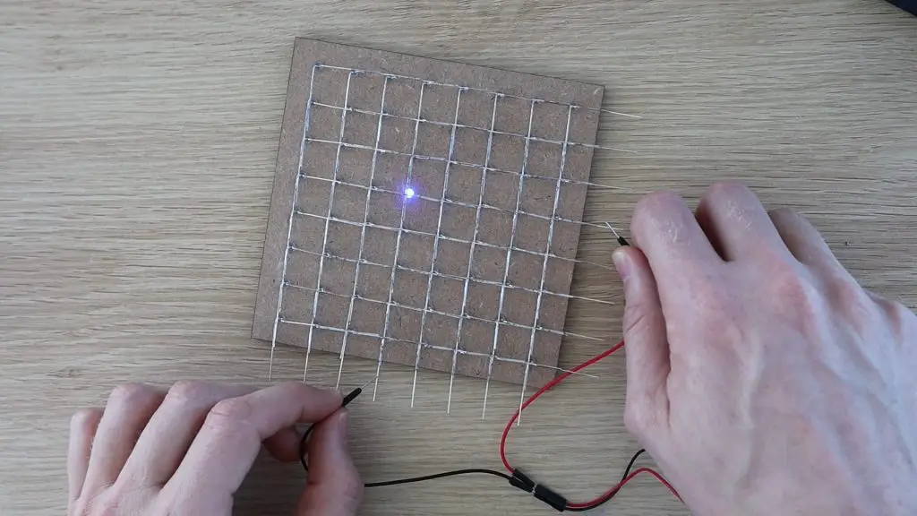
I then tested the LEDs again, this time testing the soldered connections. I used a small battery pack for this and just ran the leads over the columns and rows, checking that each LED lit up. I was glad I did this as I found two bad connections on my first layer.
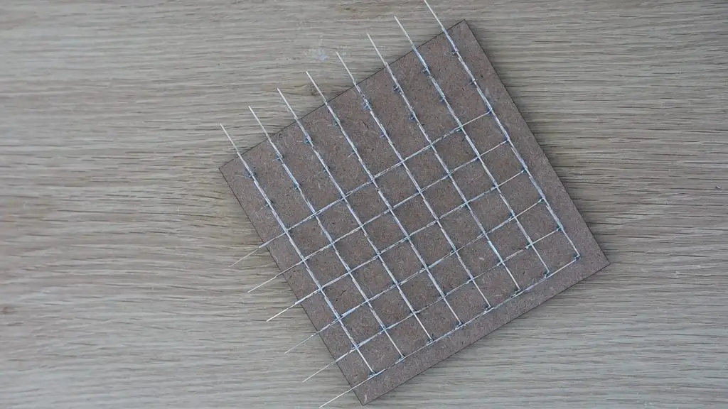
I then carefully removed the layer of LEDs from the template, trying not to bend the legs of the LEDs.
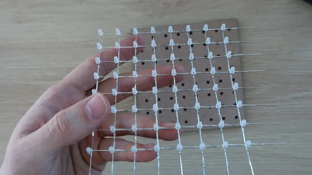
I was worried that I might have damaged some of the joints when removing the LEDs, so I tested this layer again once I removed it from the template.
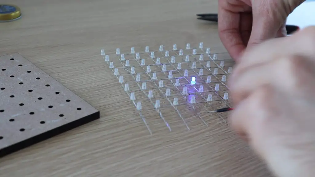
I tested the subsequent layers only after removing them from the template. The next few went a lot better, but I did still find one or two bad connections, and one LED installed the wrong way around.
Creating these layers is the most time-consuming part of the build, but time spent here will result in a much neater looking cube down the line. It’s also definitely worth taking the extra minute or two between layers to test all of the connections. Even fixing a single bad joint once the cube is assembled will be near impossible without damaging it when taking it apart again.
Soldering The PCB Components
Once all of the layers of LEDs were made, I got started with soldering the components into place.
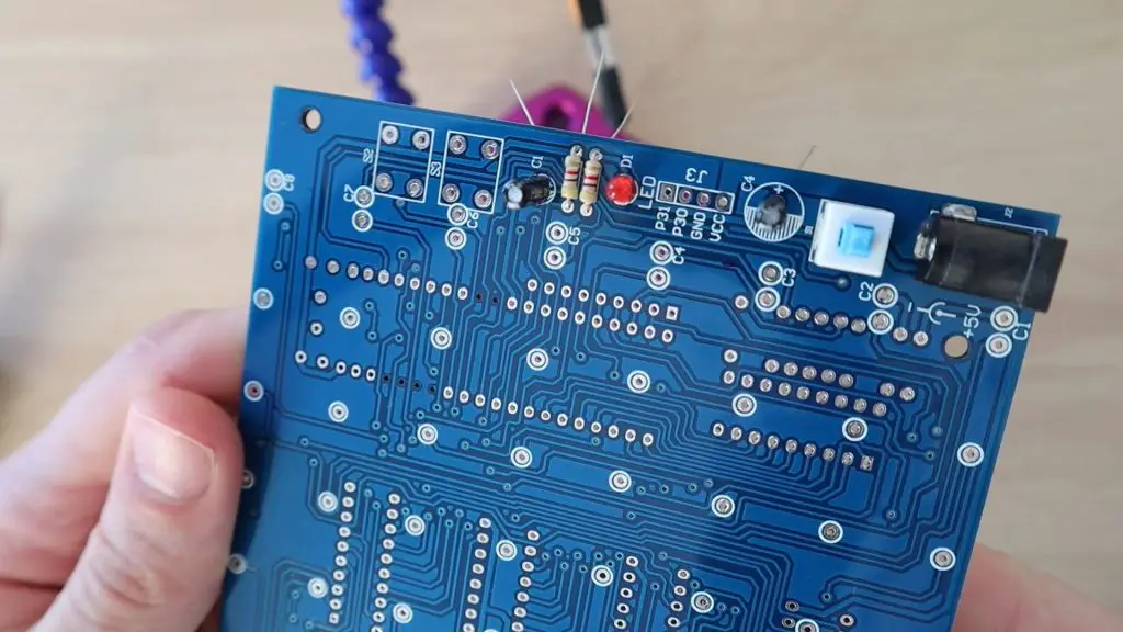
This was where some guesswork came in. It was pretty obvious when making the layers that the LEDs had to be connected in a particular way, but it’s less obvious which capacitors and resistors go in which places on the PCB when it isn’t labeled.
The two electrolytic capacitors were the same value, despite the markings on the PCB being different sizes, so I just installed those in the two available spots. The ceramic capacitors were all the same size, although there were three supplied and only two spots on the PCB for them. I also noticed that there were two different value resistors supplied, 2 of one resistance and 8 of another. I noticed that the PCB had two resistors on one side and 8 on the other, so I decided to install them with two of the same on one side and the 8 others on the other side and hope for the best.
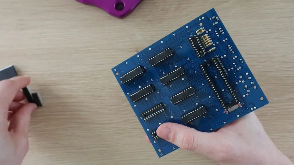
There are three different size chips. The ones that are the same size are all the same, so those are quite easy to figure out and the remaining components could be figured out based on the PCB holes.
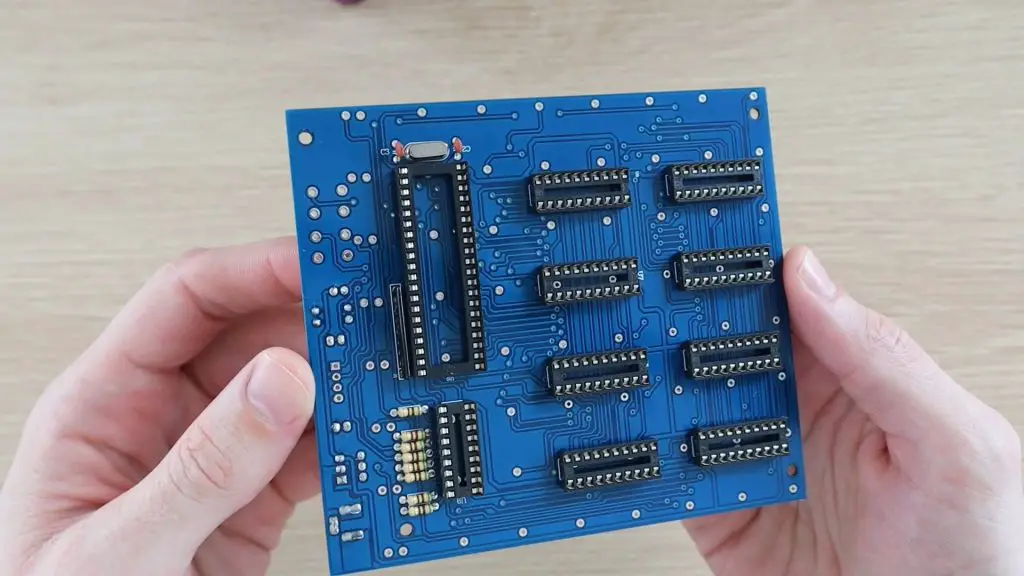
The final part of the PCB assembly is to mount these LED leg holders onto the board to plug the LEDs into. I cut the strips up into individual pins and then broke the plastic off of them. I then installed one on each of the holes on the PCB. Luckily these could be installed from the component side of the PCB as the back side of some of these pins were covered by the IC sockets, something which I hadn’t thought about earlier.
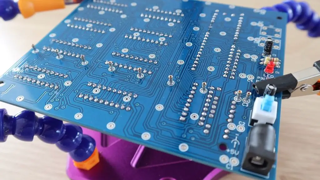
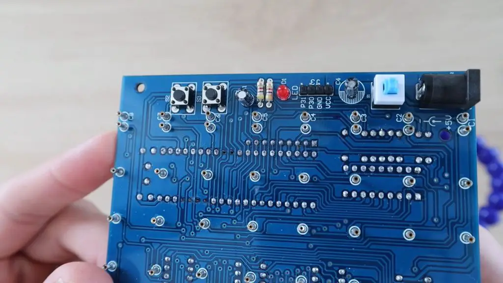
I also noticed that on the PCB there are laocations for some header pins and two pushbuttons, but the components weren’t supplied. I assumed that the header pins are for programming the chip and the pushbuttons could be used to change the display currently being run on the cube, but this probably wasn’t preloaded onto the chip either. I decided to install these components as I had some pushbuttons and pins lying around and I wanted to be able to re-program the chip later as well.
Assembling The Cube Layers
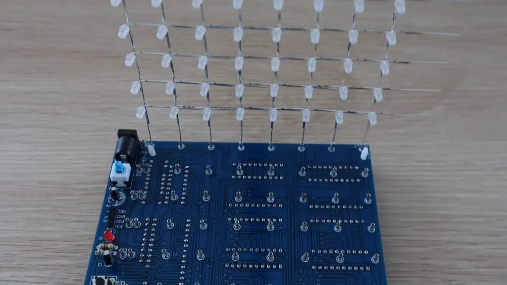
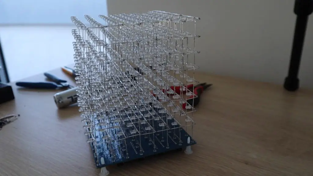
Now that the components are all in place, I could plug the LED layers in.
From other cubes I’ve seen online, I assumed that the positive legs of the LEDs went into the holes directly underneath the cube for the columns and that the negative legs would get joined in layers and connected to the holders alongside the cube. It turned out that the negative legs on my LED layers should have been on the other side, as that was the back side of the cube, but this doesn’t really make much difference.
First LED layer in place.
I then installed them remaining LED layers.
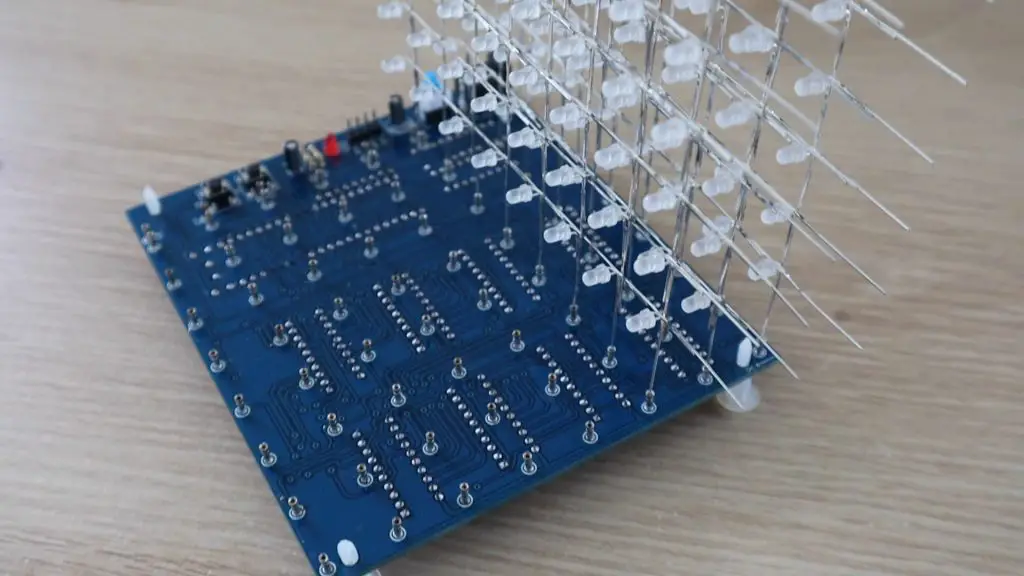
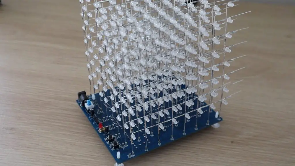
Once the layers were installed, I bent the negative legs at 90 degrees to join each layer together and soldered them together.
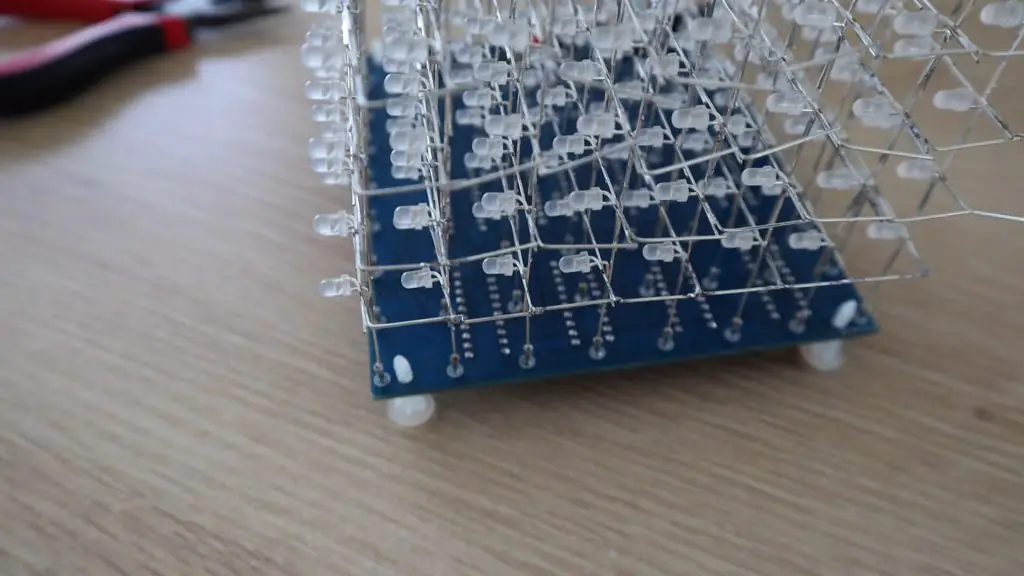
The next mystery was to decide which layer to connect to which numbered holder. I wasn’t sure if pin 8 was to go to the bottom layer or top layer? One diagram in another cube’s manual had the layers labelled with 1 being the top layer and the image alongside clearly showing the bottom layer being wired to 1.
I decided to temporarily connect these are there was a good chance my guess would be wrong.
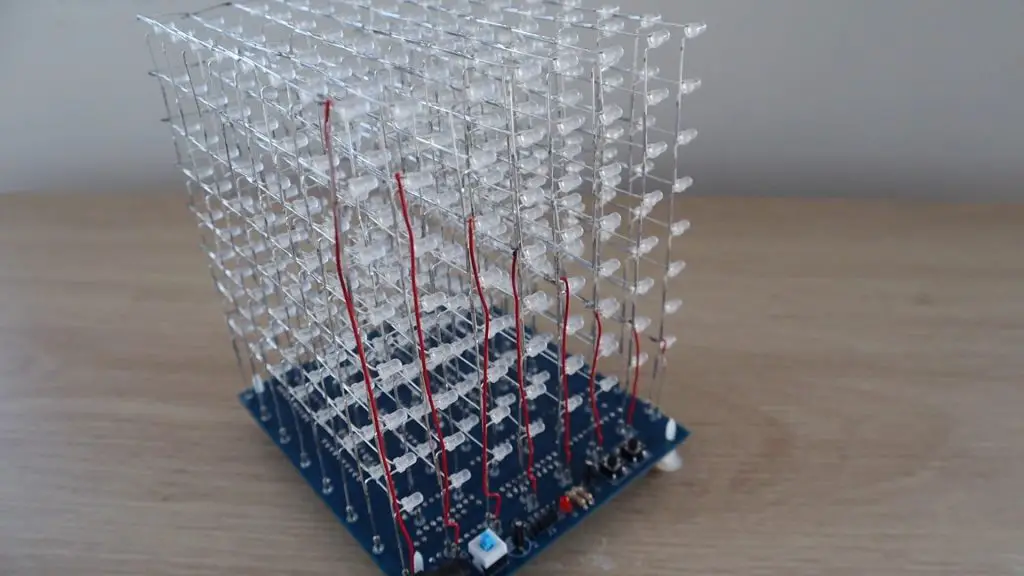
Another issue was that the red insulated wire supplied to connect the layers to the holders was too short by 2-3cm. I didn’t waste any of it with incorrect lengths or stripping too much wire, so I’m not sure why it was too short. I made a plan for the shortest connection and was then ready to power up the cube.
Powering Up the Cube
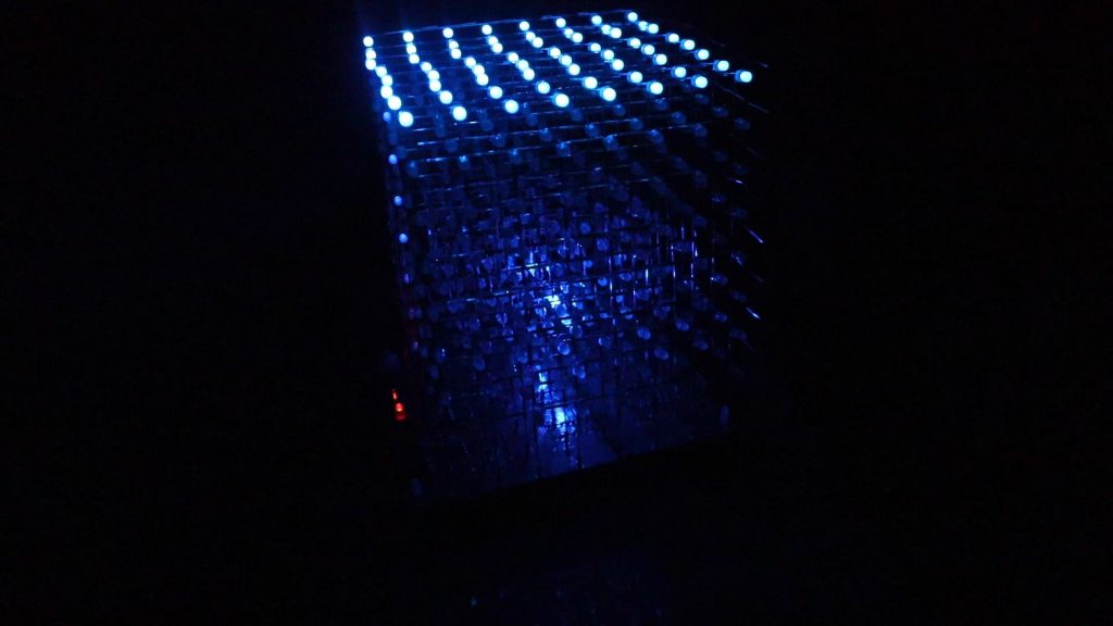
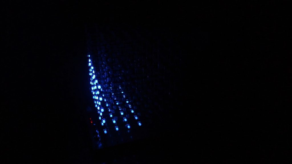
I plugged the power supply into a USB charger and pushed the switch to turn it on.
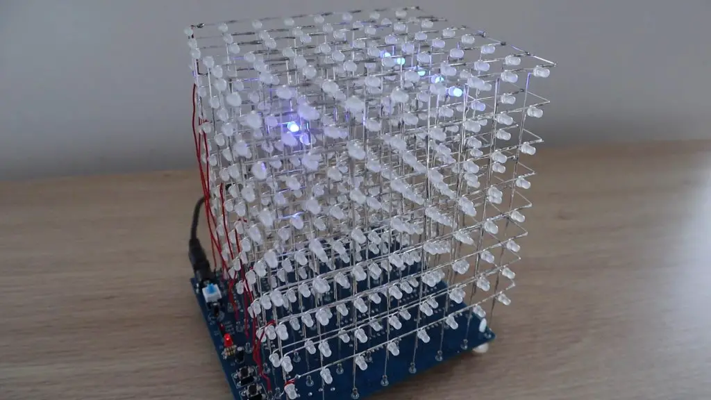
The built-in program is a bit odd in the beginning and its not really clear if the of the layers are working or not working correctly. I would have thought that a good initial test would be to light up all LEDs or at least the layers sequentially.
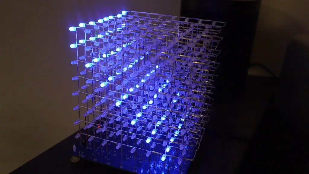
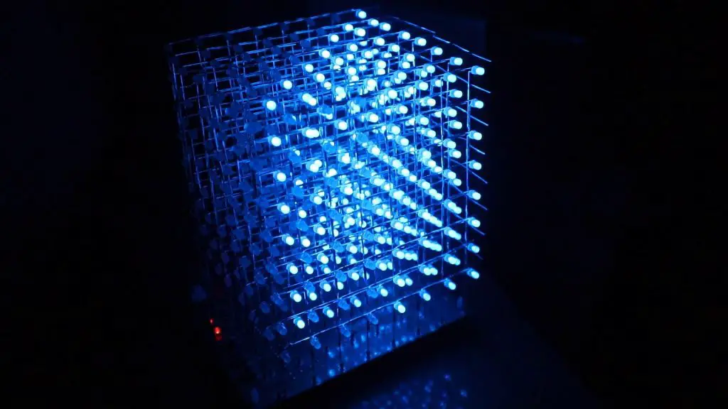
I left it running and eventually some recognizable patterns started emerging and it looked like I had guessed the layers correctly. There was a typical “rain” type animation where the LEDs drop from the lit-up top layer, and the top layer was actually at the top of the cube, so I assume that I’ve got the layer numbers correct. If they were the wrong way around then the rain would fall upwards.
As expected, the buttons don’t seem to do anything, but I’ll be looking to program them to change what is being displayed on the cube once I figure out how to program it. It also seems like the resistors are correctly installed, there aren’t any obvious bright or dim rows or columns.
Next I’m going to try and figure out how to program it and I’ll be making a clear acrylic case for it as well.
Have you tried building your own 8x8x8 LED Cube? How did it go and did you build it from scratch or use a kit? Let me know in the comments section below.
Friendly.
I also made an 8x8x8 with stc module and music.
Unfortunately I burned the first chip (plate upside down) the second kit was nice.
It takes a long time to fold all the led pin. On the other hand, I assembled in groups of 8 and tested each led. So not individually. It took me a long time. It is not Arduino compatible (not verified) but with a rather well explained assembly instructions. I used a perforated cardboard for mounting the LEDs. I have no laser cutter and no 3d printer at the time of assembly.
It’s still fun to do. You can see the cube in this link at the end of the answer.
Is an AliExpress kit. (Amazon not ship most product in my country.)
https://fr.quora.com/Pratiquez-vous-un-loisir-cr%C3%A9atif-tricot-broderie-dessin-scrapbooking-mosa%C3%AFque-journaling-Pouvez-vous-nous-montrer-vos-cr%C3%A9ations/answer/Michael-Aramini?ch=10&share=d43333d9&srid=pqVEz
Hi Michael,
Your cube looks great, really neat job on the soldering! What are the green strips on the side which you’ve used to connect the LED layers? Did those come with the kit?
Yes it was with the kit. Really convenient. But not easy to solder at the pcb.
A photo of the pcb here https://ibb.co/nCS2R24
Your kit is more careful on the led connections. With laser cutting it is better than cardboard.
They look pretty cool!
Yes, I found the laser-cut template to be a big help in assembling the LEDs.
How many hours did you approximately spend assembling/soldering?
I made a 4x4x4 last year with a similar rig, albeit smaller. But even with this smaller version, I still spend a couple of hours setting everything up.
It does take quite a while! I think I spent around 2 hours making up the holder to space the LEDs properly and it then took about 5 hours to solder and test all of the LED layers and another 2 hours to assemble the PCB, mount the layers, and get the cube running.
I’ve got exactly the same kit – it even came with the same plastic box.
Like you, I left it for ages before trying to assemble it. However, I did have some instructions.
The product page on BangGood has a link to them, https://www.banggood.com/Geekcreit-8x8x8-LED-Cube-3D-Light-Square-Blue-LED-Flash-Electronic-DIY-Kit-p-1055438.html?cur_warehouse=CN&rmmds=search
However, it seems that over time the link has gone bad. The original archive was called SKU331661.zip and googling that gives you some other blogs/web pages that help with assembly (but not the original archive).
I’ve got a copy of the archive in case anyone wants it, just drop me an email. However, the instructions are not good – better instructions are available on blogs like this one.
Thanks for sharing this information Doug
Hello sir could you please share me SKU331661.zip file it will be great.
Thank you
I see this is an old blog but I am now building my own 8x8x8 led cube. Unfortunately, I purchased the same kit 5 years ago and tossed it to the side because no instructions were provided. Anyways, I tested all the supplied 550 leds and am now soldering the components to the PCB. I noticed my kit is missing the LED leg holders that mount onto the PCB. Where can I get these or is there another name to search for them to buy? Also, I noticed you used a logic gate that has hollow in the middle with a “G” and “40” on it. There is an STC12C5A60S2 series MCU that’s also provided with this kit. So is there a reason you use that particular logic gate instead of the STC?
Bro do we need to program this ic
Or it is pre programed .
Please tell