Last month, I built an Arduino based reaction timer game, which allows you to challenge your friends and family to see who has the fastest reaction time. We managed to get our times down to around 160 milliseconds and I’ve seen videos of people who can get down to 120 milliseconds, but now I want to know – How fast can an Arduino react to the same game?
Here’s a video of the test, have a look at it to see the Arduino react to the reaction timer’s LED, otherwise read on for the full write-up and details.
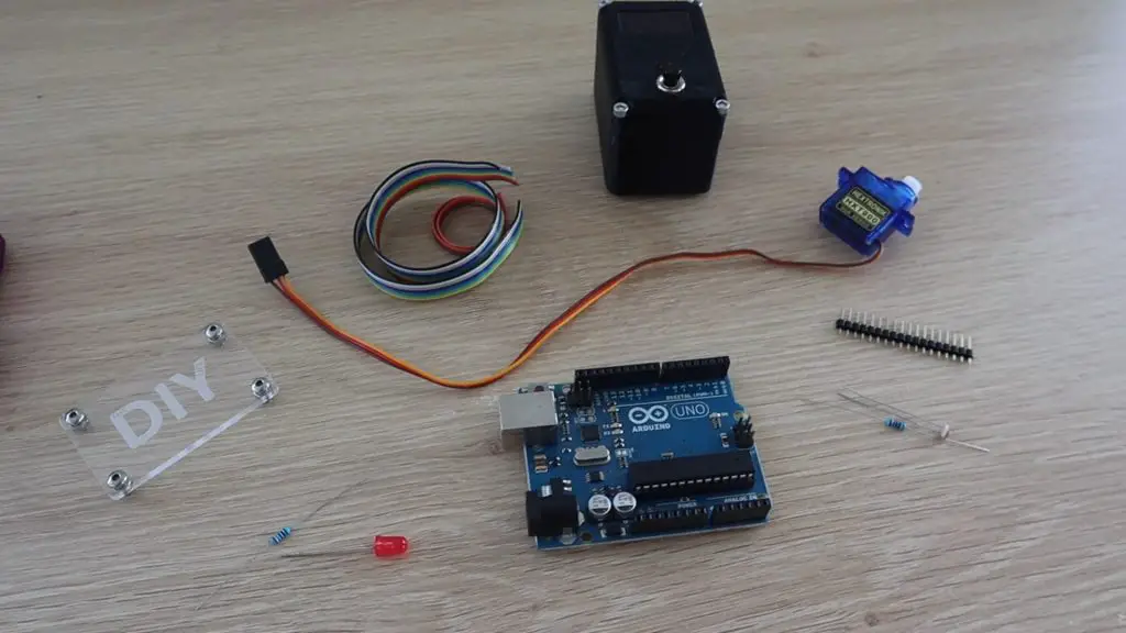
What You Need For This Test
- Your Reaction Timer Game
- Arduino Uno – Buy Here
- LDR – Buy Here
- Resistors – Buy Here
- Micro Servo – Buy Here
- Optional LED – Buy Here
Setting Up The Test Rig
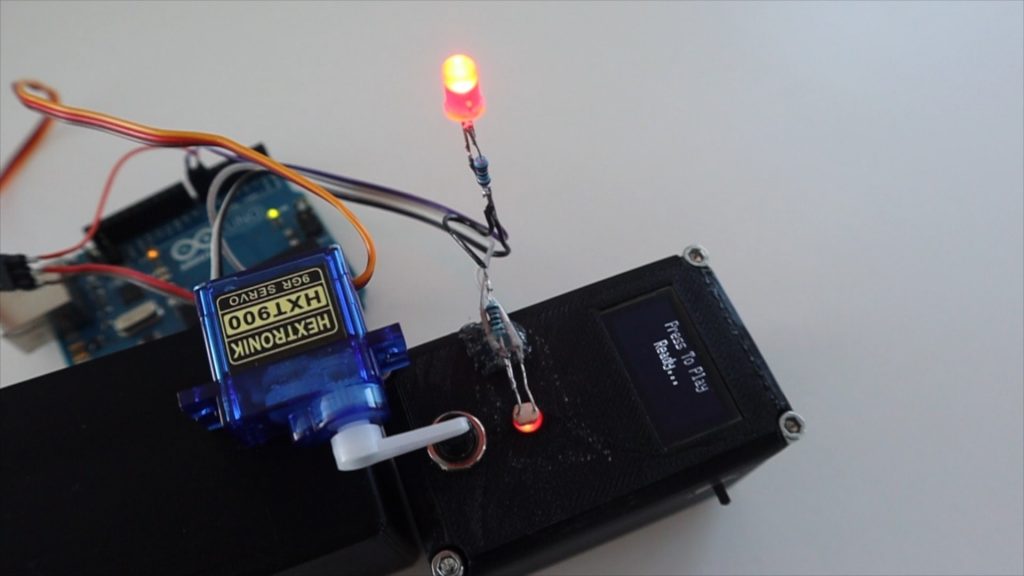
In order to test the Arduino’s reaction time, we’d need a sensor to detect the light coming from the LED on the game and then an actuator to push the button to stop the timer.
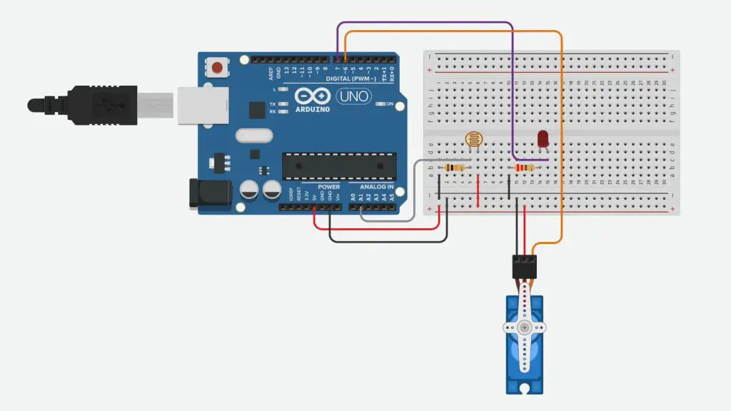
I built a simple setup with an LDR to detect the LED’s light and a micro-servo to push the button. I also included an LED so that we can see if there is any delay between the Arduino telling the servo to move and the servo actually pushing the button since there is a motor to spin up and a number of gears between the motor and the servo arm.
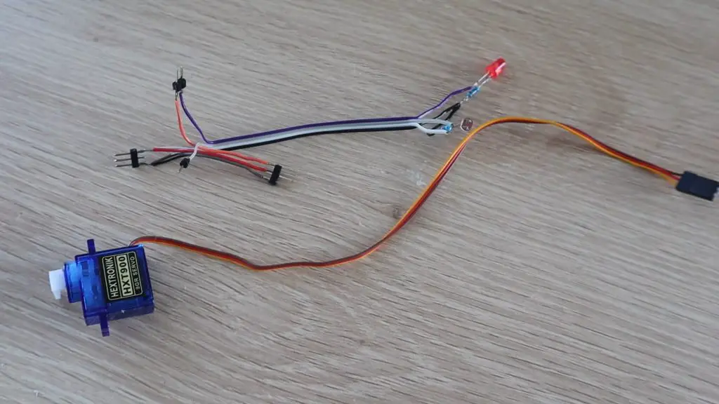
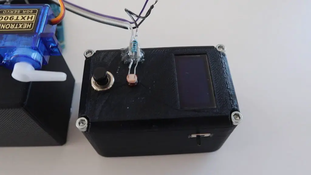
I soldered the components together using a few strips of ribbon cable and some header pins.
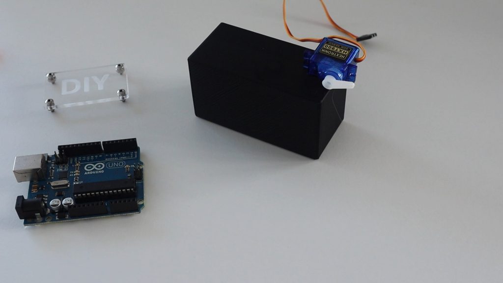
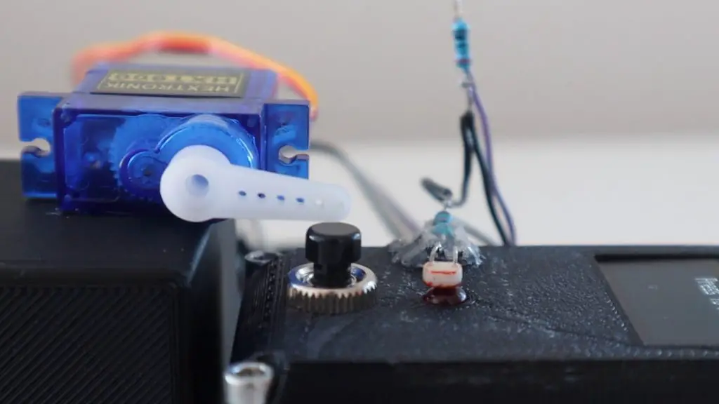
I then found a plastic base which was the right height to mount the servo on so that it could be positioned just above the button.
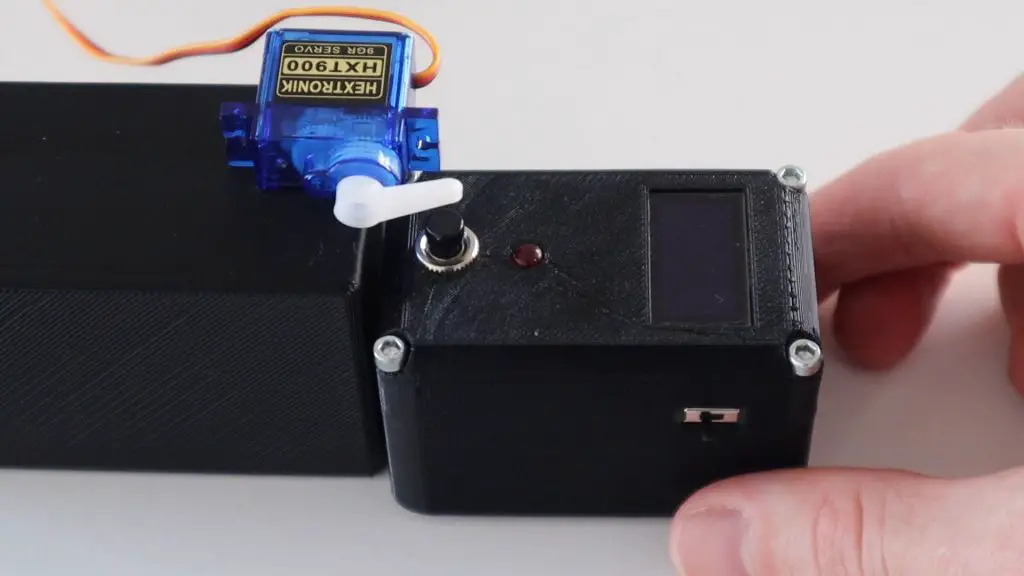
Next you’ll need to position the LDR as close to the LED as possible. I glued the resistor onto the side of the game using a glue gun and could then adjust the legs of the LDR to position it directly over the LED.
Now let’s have a look at the code.
//Michael Klements
//The DIY Life
//7 May 2020

#include <Servo.h>

Servo react;        //Create a servo object to control the reaction servo
int lightOn = 0;    //Variable to read in LDR value

void setup()
{
  //Serial.begin(9600);
  react.attach(6);    //Set the servo pin to pin 9
  pinMode(7, OUTPUT);   //Output pin for LED
  react.write(80);    //Set the servo to an initial position just above the button
}

void loop()
{
  lightOn = analogRead(A0);   //Read the output from the LDR
  //Serial.println(lightOn);
  if (lightOn > 800)
  {
    digitalWrite(7, HIGH);            //Light up the LED
    react.write(65);                  //Move the servo to push the reaction button
    delay(600);                       //Wait 400 milliseconds
    react.write(80);                  //Move the servo back to the initial position
    digitalWrite(7, LOW);             //Turn the LED off
  }
}We start by including the servo library to control the servo.
We then create a servo object called react to control the servo and create a variable to store the value read from the LDR.
In the setup function we set the servo pin number, then set the LED pin as an output and set the servo position slightly above the reaction button.
In the loop function, we read in the LDR sensor level, then compare it to the light set point. If the measured level is greater than the set point, then we turn the LED on and then move the servo downwards to push the button. We then wait 400 milliseconds for the servo to move and then move the servo back up for the next push and turn the LED off again..
I’ve also included a serial monitor printout of the sensor value which is used initially to measure the game’s LED set point. You’ll need to run the game and see what value is measured by the sensor when the reaction timer’s LED is on and then update this value in the code accordingly. Once you’ve done this, then remove or comment out this code so that it is now slowing down the loop for the actual test. We’ll look at this in the next step.
Calibrating The Light Sensor
If we upload the code and then open the Serial Monitor, we get a stream of input values read from the sensor, detecting the ambient light. Now press the button on the reaction timer to start a game and look out for the change in values when the LED comes on.
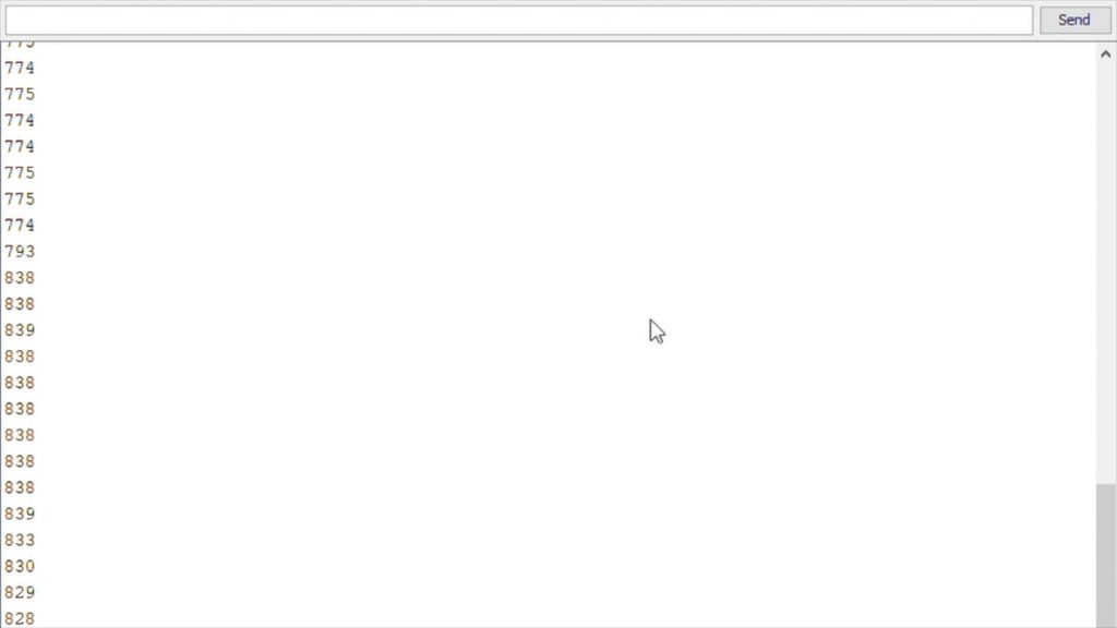
You can see that we get a reading of around 775 when the LED is off and it goes up to around 830 when the LED is on.
We can now go change the setpoint value to a value just above the off value so that it triggers the servo movement as soon as the LDR starts to register the change in light. You want it to trigger as the LDR starts detecting the light change as the LDR will “slowly” ramp up to the maximum value over a couple of milliseconds.
Remember to comment out the Serial communication for the final version as you want the code to be as quick as possible.
Let’s upload the code and see how it quick it is.
Testing The Reaction Time Of The Arduino
Press the button once to start the game and then quickly position it under the reaction servo.
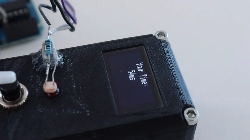
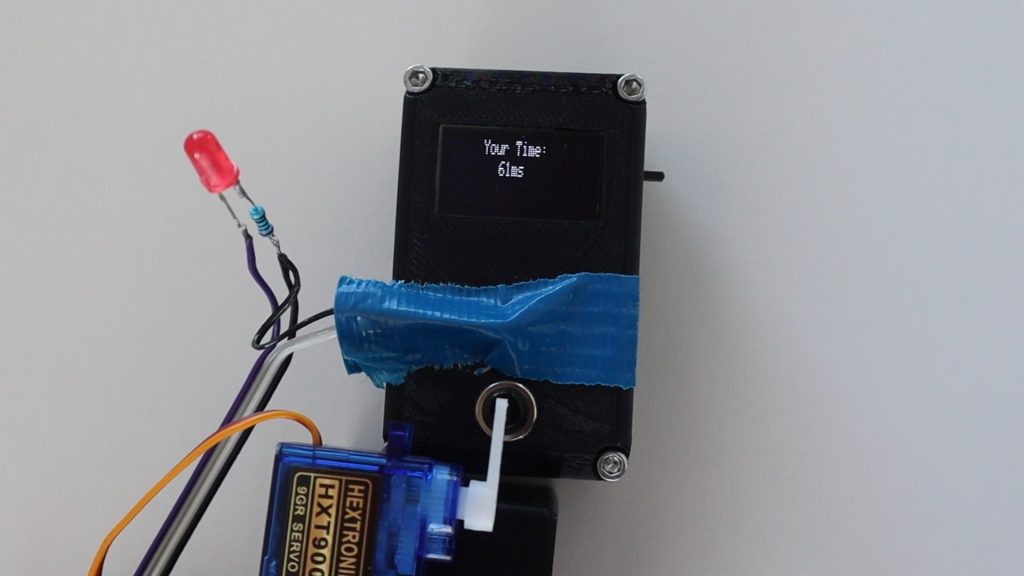
For the first run, we get a reaction time of 54 milliseconds, which is pretty quick considering we have to wait for the servo to move to push the button as well.
I tested it a couple of times like this and consistently got around 50 to 60 millisecond reaction times.
Watching one in slow motion (included in the video at the beginning), you can see that the LED comes on really quickly after the reaction timer’s LED turns on, but there is a bit of a delay in getting the servo to move. By looking at the individual frames, I calculated that it takes around 8 milliseconds LED to come on after the reaction timer’s LED is turned on, the servo then takes around 50 milliseconds to press the button after this.
I then tried to see if making it darker around the LDR with some tape would result in a faster response time. It didn’t really make much of a difference, although there was a very slight improvement of around 1-3 milliseconds.
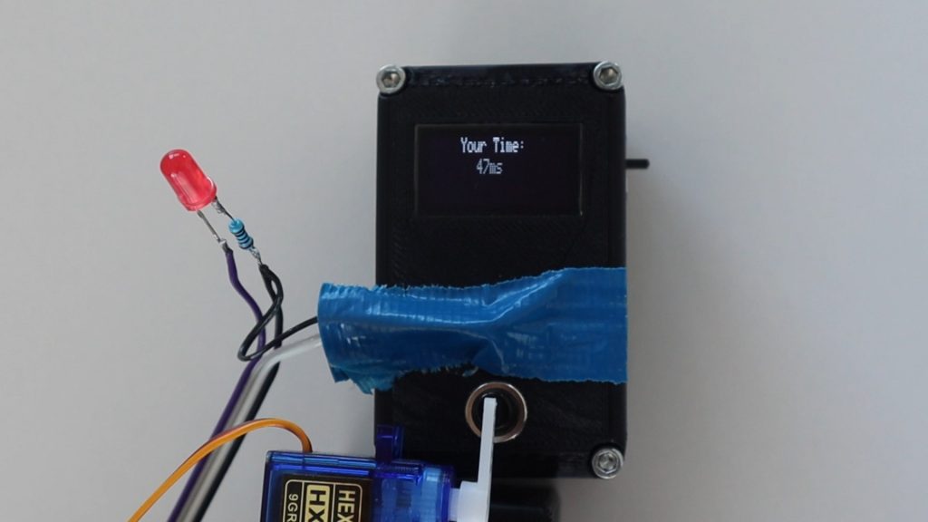
I also tried disabling the LED so that the Arduino just had to move the servo, this improved the reaction time by almost 10 milliseconds, so I got times around the mid-forties.
Conclusion
So from this test, we can see an Arduino react to an external light source in under 10 milliseconds, the servo movement takes up most of the reaction time from there. With the movement of a servo, the response time is just less than 50 milliseconds.
There are ways to further improve an Arduino’s response time by using Direct Port Manipulation, but this is probably not going to make a significant difference in this example, as the delays in the LED lighting up, the LDR responding to the light and the second LED lighting up is much more significant than the amount of time the Arduino takes to respond to the input.
Have you tried building any projects which required your Arduino to react quickly? What have you built? Let me know in the comments section below.
I like it! There are probably some improvements that could be made by trimming the servo arm so that it is slightly pressing the button. You could also set it up to respond on release. Have the servo push the button down, hold it, and release on light up.
Just thinking about how you might be able to get it as low as possible by reducing the distance the servo arm needs to travel.
Best regards!