In this guide, I’ll show you how to connect the ADXL345 3 axis accelerometer to an Arduino using the I2C communication protocol. The ADXL345 is a powerful accelerometer board which provides high resolution (13 bit) measurements up to +/- 16g. The data output is digital and can be accessed through either a 4 wire SPI or I2C digital interface. We will go through the basic connections as well as some of the core functions of the board in order to get your first accelerometer project up and running.
The ADXL345 supports both SPI and I2C communication, however, we are going to be using the I2C communicaiton protocol for two reasons; the first is that it leaves all of your analogue and digital pins open. I2C communication uses the SCL and SDA pins which are separate to your analogue and digital IO pins, unlike SPI communication which requires 4 IO pins. This leaves all of your IO pins available for your project. The second is that you need a 3.5V logic level converter if you are using a 5V Arduino (which are more common) with SPI communication as the accelerometer’s pins are only rated for 3.5V and not the 5V that the Arduino outputs.
This project assumes that you know the basics of Arduino programming, otherwise follow our guide on getting started with Arduino.
What You Need For Your ADXL345 Accelerometer Connection
Breadboard Connection
- An Arduino (Uno Used In This Guide) – Buy Here
- ADXL345 Accelerometer Board – Buy Here
- Breadboard – Buy Here
- Breadboard Jumpers – Buy Here
- 8 Pin Male Header Strip – Buy Here
Prototype Shield Connection
- An Arduino (Uno Used In This Guide) – Buy Here
- ADXL345 Accelerometer Board – Buy Here
- Arduino Prototyping Shield – Buy Here
- 8 Pin Male Header Strip – Buy Here
- 8 Pin Female Header Strip – Buy Here
- Shield Male Header Strip Kit – If Not Included On Shield
- Thin Insulated Wire – Buy Here
How To Connect The Accelerometer To Your Arduino
Before we start with the physical connections to your Arduino, lets have a look at the pins available on the ADXL345 board and their functionality.
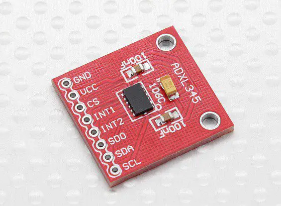
The board has 8 pins with the following functions:
- GND – Ground
- VCC – Supply Voltage
- CS – Chip Select
- INT1 – Interrupt 1 Output
- INT2 – Interrupt 2 Output
- SDO – Serial Data Output (SPI) / I2C Address Select
- SDA – Serial Data Input (SPI) / I2C Serial Data
- SCL – Serial Communications Clock
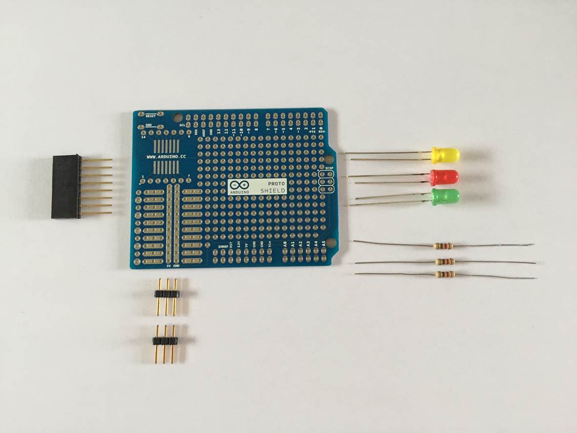
Regardless of whether you are using a breadboard or assembling your board onto a prototyping shield, you’ll need to solder an 8 pin male header strip onto the terminals of your accelerometer board. You then use this strip to plug directly into a breadboard or you can plug it into an 8 pin female header strip which you’ll solder onto your prototyping shield.
I2C Connection Circuit Diagram
Now that you understand what each pin is being used for and you’ve soldered an 8 pin male header strip onto your accelerometer board, lets have a look at the I2C connection circuit diagram.
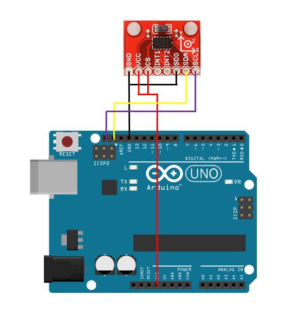
It is important to note that the Vcc pin is connected to the Arduino’s 3.3V supply and not the 5V supply, if you connect this incorrectly you may permanently damage your accelerometer board.
You’ll also notice that this connection method leaves all of your IO pins available for your project requirements.
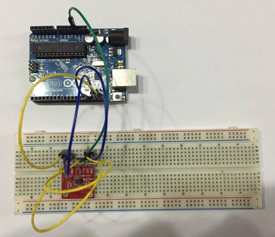
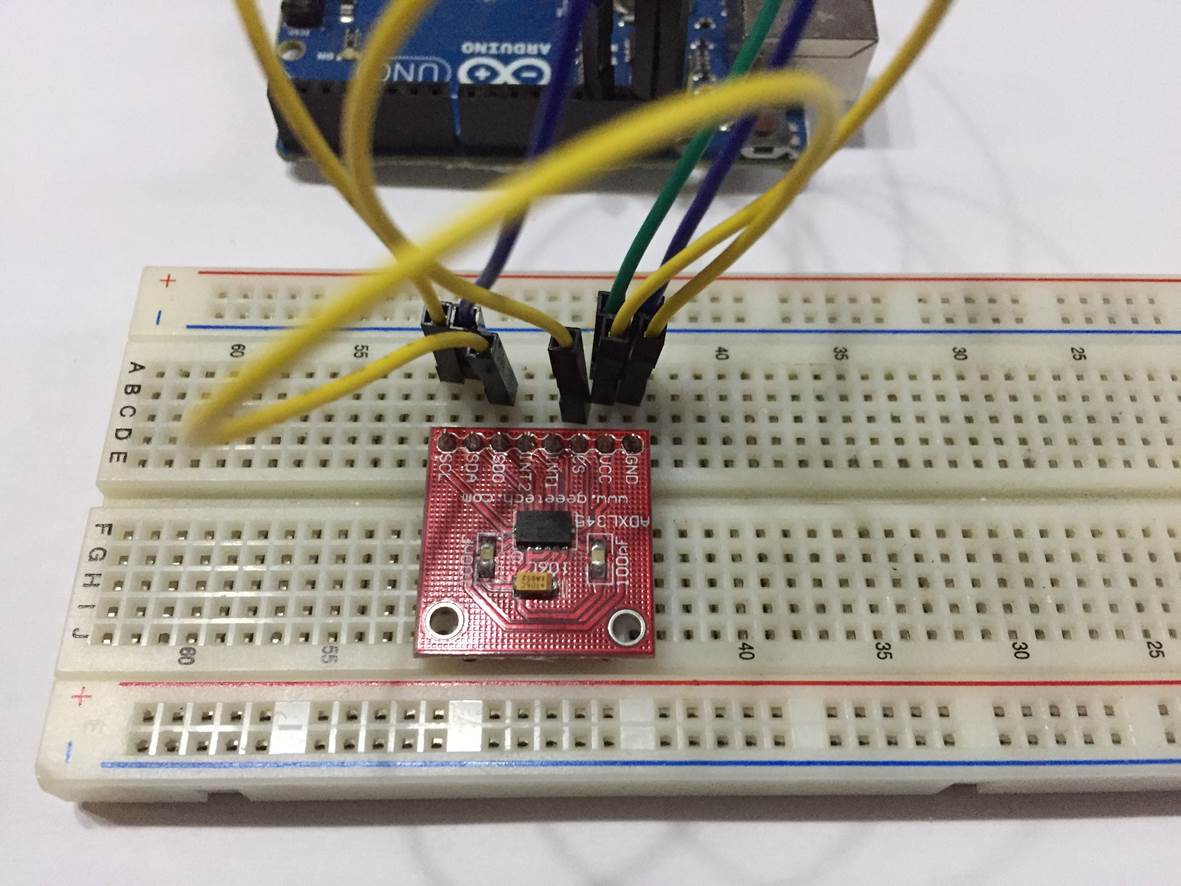
Assemble The Components Onto A Breadboard
The breadboard assembly of this circuit is a really easy way to test the board, it does however have some limitations as this board relies on a good connection to the Arudino to transfer data and you’ll obviously need to move the accelerometer board around a bit to test that it is working. This may cause intermittent communication problems.
Plug the accelerometer board into your breadboard and connect the jumpers across to your Arduino. The final connection should look as follows.
Assemble The Components Onto A Prototyping Shield
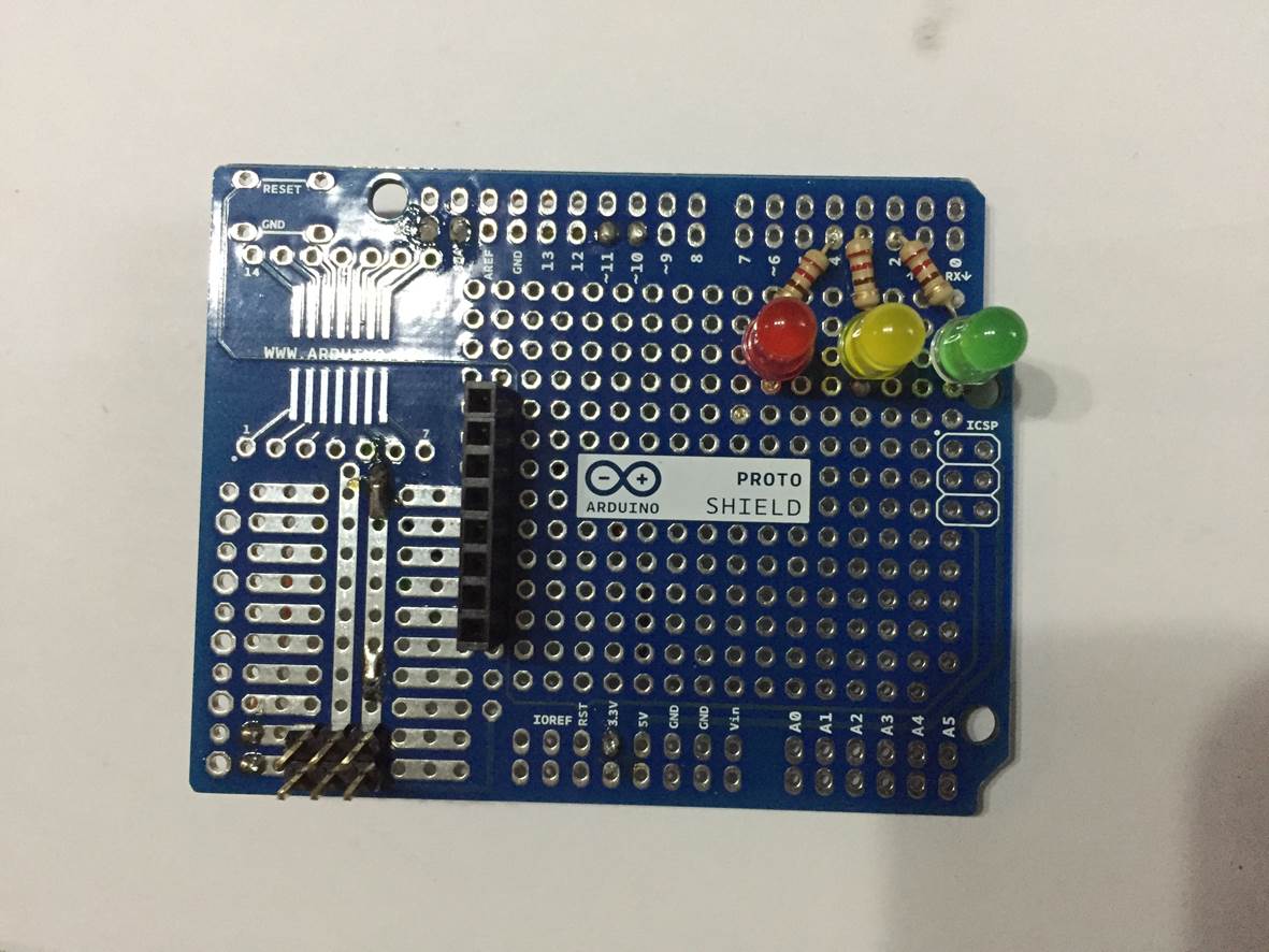
Assembly onto a prototyping shield provides a more reliable connection to the accelerometer although it does require a bit more effort. Solder a 8 pin female header onto the shield for the accelerometer and make the connections to the required pins using some thin insulated wire on the underside of the board. Ensure that you choose a position on the prototyping shield which does not interfere with the components on the Arduino when plugged in.
I have added a few more components to the prototyping shield in order to drive two servos and provide a few LEDs for indication.
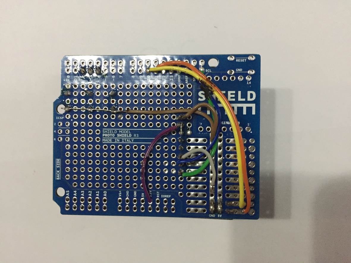
All of the wiring connections have been made on the underside of the prototyping board to keep them protected.
The accelerometer board can then be plugged into the prototyping shield.
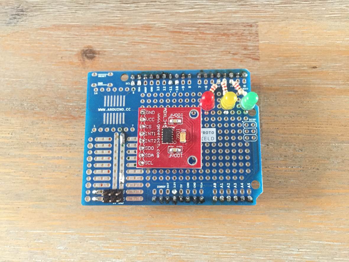
Double check that all of your connections are correct and your board will then be ready to be tested with the sketch.
Upload The Sketch
The sketch is based on the Adafruit Sensor Library and the ADXL345 library, click on the links provided to download the libraries and install them into your Arduino IDE.
Once you have these two libraries installed, you can load the following sketch and upload it to your Arduino. You’ll need to open your Serial monitor to see the results coming from your board.
The sketch is built into the Adafruit library and can be accessed by clicking on File > Examples > Adafruit_ADXL345 > sensortest
#include <Wire.h>
#include <Adafruit_Sensor.h>
#include <Adafruit_ADXL345_U.h>

/* Assign a unique ID to this sensor at the same time */
Adafruit_ADXL345_Unified accel = Adafruit_ADXL345_Unified(12345);

void displaySensorDetails(void)
{
  sensor_t sensor;
  accel.getSensor(&sensor);
  Serial.println("------------------------------------");
  Serial.print  ("Sensor:       "); Serial.println(sensor.name);
  Serial.print  ("Driver Ver:   "); Serial.println(sensor.version);
  Serial.print  ("Unique ID:    "); Serial.println(sensor.sensor_id);
  Serial.print  ("Max Value:    "); Serial.print(sensor.max_value); Serial.println(" m/s^2");
  Serial.print  ("Min Value:    "); Serial.print(sensor.min_value); Serial.println(" m/s^2");
  Serial.print  ("Resolution:   "); Serial.print(sensor.resolution); Serial.println(" m/s^2");
  Serial.println("------------------------------------");
  Serial.println("");
  delay(500);
}

void displayDataRate(void)
{
  Serial.print  ("Data Rate:    ");

  switch(accel.getDataRate())
  {
    case ADXL345_DATARATE_3200_HZ:
      Serial.print  ("3200 ");
      break;
    case ADXL345_DATARATE_1600_HZ:
      Serial.print  ("1600 ");
      break;
    case ADXL345_DATARATE_800_HZ:
      Serial.print  ("800 ");
      break;
    case ADXL345_DATARATE_400_HZ:
      Serial.print  ("400 ");
      break;
    case ADXL345_DATARATE_200_HZ:
      Serial.print  ("200 ");
      break;
    case ADXL345_DATARATE_100_HZ:
      Serial.print  ("100 ");
      break;
    case ADXL345_DATARATE_50_HZ:
      Serial.print  ("50 ");
      break;
    case ADXL345_DATARATE_25_HZ:
      Serial.print  ("25 ");
      break;
    case ADXL345_DATARATE_12_5_HZ:
      Serial.print  ("12.5 ");
      break;
    case ADXL345_DATARATE_6_25HZ:
      Serial.print  ("6.25 ");
      break;
    case ADXL345_DATARATE_3_13_HZ:
      Serial.print  ("3.13 ");
      break;
    case ADXL345_DATARATE_1_56_HZ:
      Serial.print  ("1.56 ");
      break;
    case ADXL345_DATARATE_0_78_HZ:
      Serial.print  ("0.78 ");
      break;
    case ADXL345_DATARATE_0_39_HZ:
      Serial.print  ("0.39 ");
      break;
    case ADXL345_DATARATE_0_20_HZ:
      Serial.print  ("0.20 ");
      break;
    case ADXL345_DATARATE_0_10_HZ:
      Serial.print  ("0.10 ");
      break;
    default:
      Serial.print  ("???? ");
      break;
  }
  Serial.println(" Hz");
}

void displayRange(void)
{
  Serial.print  ("Range:         +/- ");

  switch(accel.getRange())
  {
    case ADXL345_RANGE_16_G:
      Serial.print  ("16 ");
      break;
    case ADXL345_RANGE_8_G:
      Serial.print  ("8 ");
      break;
    case ADXL345_RANGE_4_G:
      Serial.print  ("4 ");
      break;
    case ADXL345_RANGE_2_G:
      Serial.print  ("2 ");
      break;
    default:
      Serial.print  ("?? ");
      break;
  }
  Serial.println(" g");
}

void setup(void)
{
#ifndef ESP8266
  while (!Serial); // for Leonardo/Micro/Zero
#endif
  Serial.begin(9600);
  Serial.println("Accelerometer Test"); Serial.println("");

  /* Initialise the sensor */
  if(!accel.begin())
  {
    /* There was a problem detecting the ADXL345 ... check your connections */
    Serial.println("Ooops, no ADXL345 detected ... Check your wiring!");
    while(1);
  }

  /* Set the range to whatever is appropriate for your project */
  accel.setRange(ADXL345_RANGE_16_G);
  // displaySetRange(ADXL345_RANGE_8_G);
  // displaySetRange(ADXL345_RANGE_4_G);
  // displaySetRange(ADXL345_RANGE_2_G);

  /* Display some basic information on this sensor */
  displaySensorDetails();

  /* Display additional settings (outside the scope of sensor_t) */
  displayDataRate();
  displayRange();
  Serial.println("");
}

void loop(void)
{
  /* Get a new sensor event */
  sensors_event_t event;
  accel.getEvent(&event);

  /* Display the results (acceleration is measured in m/s^2) */
  Serial.print("X: "); Serial.print(event.acceleration.x); Serial.print("  ");
  Serial.print("Y: "); Serial.print(event.acceleration.y); Serial.print("  ");
  Serial.print("Z: "); Serial.print(event.acceleration.z); Serial.print("  ");Serial.println("m/s^2 ");
  delay(500);
}
You’ll need to remove the if statement in lines 112 to 114 if you’re using an Arduino Uno else you’ll get a compiler error.
In the serial monitor, you’ll get a read out of the initialisation data followed by a periodic reading of the X, Y and Z axis acceleration data. If you move the sensor around a bit, you’ll see these values changing.
You should now have enough information to take pieces from the code and use them to build your next accelerometer project.
You may be interested in building a balancing robot using one of these sensors, you could try giving it the ability to avoid obstacles with an ultrasonic sensor, have a look at our guide on Connecting An Ultrasonic Sensor To An Arduino.
Hi,
I am working on a project where I need to connect 2 ADXL345 accelerometers with Arduino UNO, can it be done ?
Hi Harinder,
What are you working on which requires two accelerometers? I’ve never tried to connect two but I can’t see why you shouldn’t be able to. You’ll probably need to use the SPI communication interface to connect them though.
Hi, i am working on project using adxl345 sensor but when i try to upload sensortest the result on my serial monitor is “Ooops, no ADXL345 detected … Check your wiring!” when i choose the jumper to another sensor it works. I have used 3 sensor adxl 345 but the result is same. How can i fix it ? and in the picture i saw you use resistor, what resistor do you use ? thank you
Hi,
I test with the serial plotter, but starts with a high value in the graphic, making it impossible to see the remaining graphic. Could you help me?
can u please provide me connections and code of arduino uno with two or multipe
adxl345 .i have trying but couldn’t success
Is there a way to change the sampling rate manually? Because the code gets my Arduino to sample at only like 100 Hz.