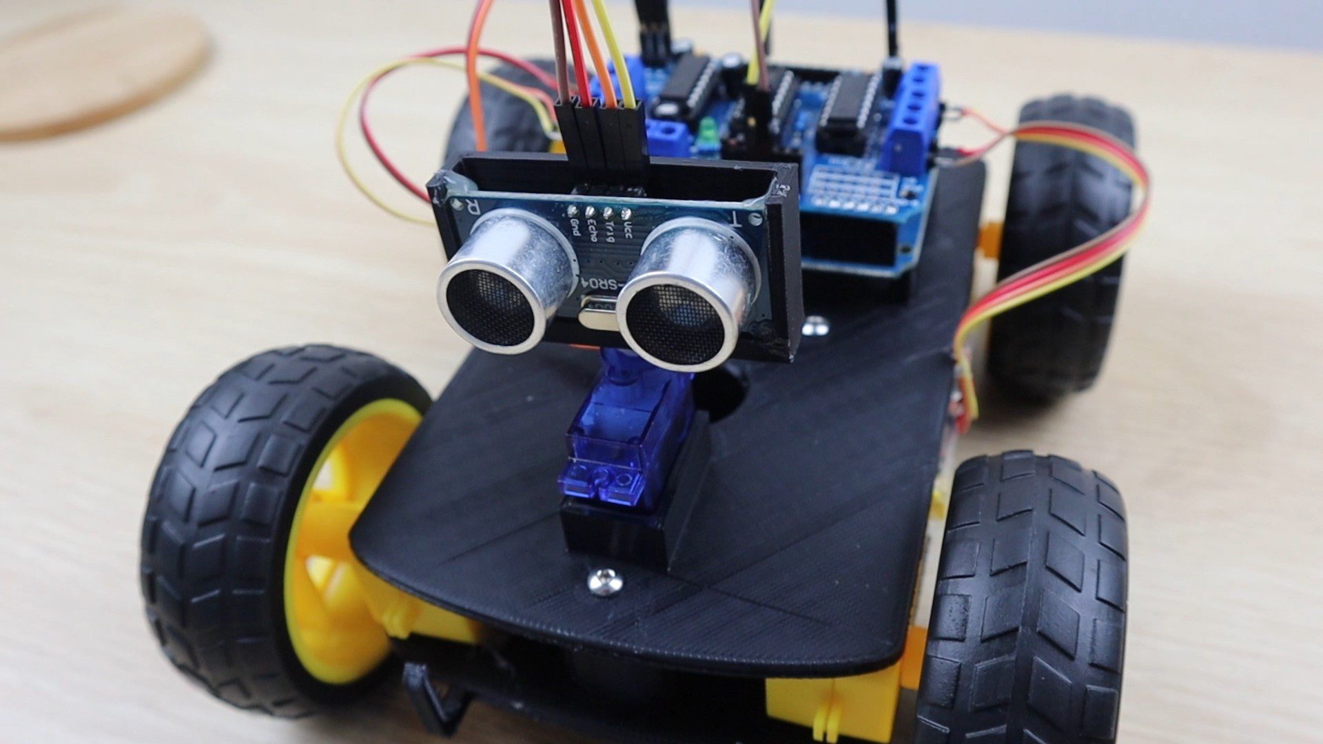
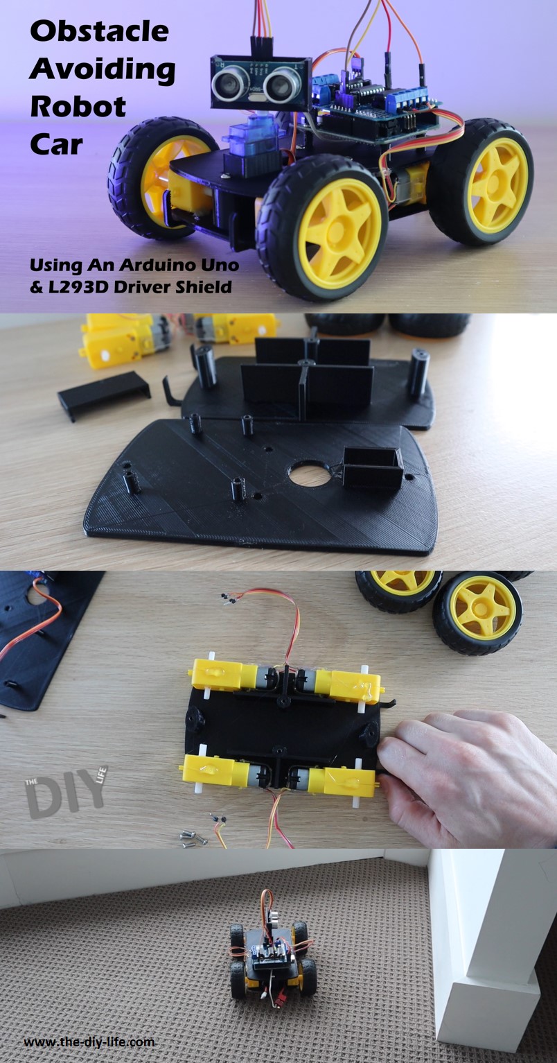
In this guide, I’ll be showing you how to build your own Arduino based obstacle avoiding robot car. The car uses a servo mounted ultrasonic sensor to detect objects in front of and on either side of the car and an L293D DC motor driver shield to drive four geared motors, one on each wheel. An Arduino Uno underneath the motor driver controls the motor shield, ultrasonic sensor and the servo.
Because all four wheels are driven, we can drive two on one side of the car forward and two on the other side backwards in order to turn the car, so we don’t need a steering mechanism and the car can turn around on the spot, instead of requiring forward movement.
Here’s a video of the build and the car running. Read on for the full step by step instructions.
Here’s What You Need To Build An Obstacle Avoiding Robot Car
- Arduino Uno – Buy Here
- L293D Motor Driver Shield– Buy Here
- Micro Servo – Buy Here
- Ultrasonic Sensor Module – Buy Here
- 4 x Geared DC Motors & Wheels – Buy Here
- 9-12V Battery Pack
- A 9V block battery can’t usually produce enough current to drive the four motors. Rechargeable battery packs for RC cars tend to work best for this project.
- 8 x M3 x 15mm Socket Head Screws – Buy Here
- Ribbon Cable – Buy Here
- Header Pins – Buy Here
How To Build Your Robot Car
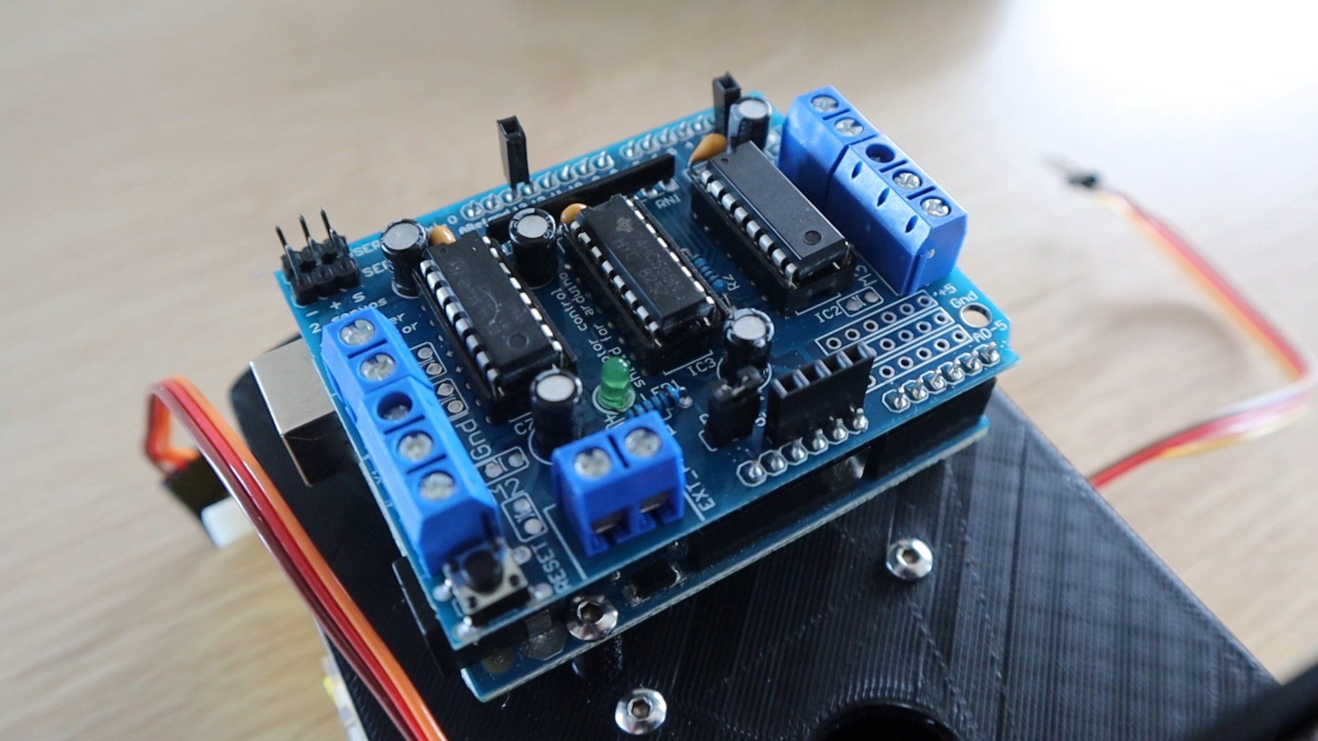
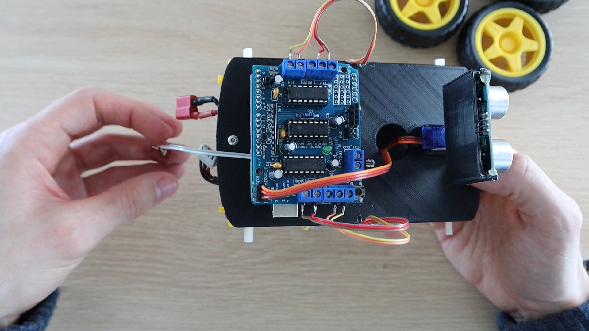
Before we start building the actual obstacle avoiding robot car, let’s take a look at the motor driver shield. The control of the motors is done through an L293D motor driver shield which uses two L293D driver chips and a shift register. It also has some power breakout pins, pins to connect two servos and a breakout for IO pin 2. Oddly, pin 2 and pin 13 are unused by the board but only pin 2 has a breakout for a solder joint.
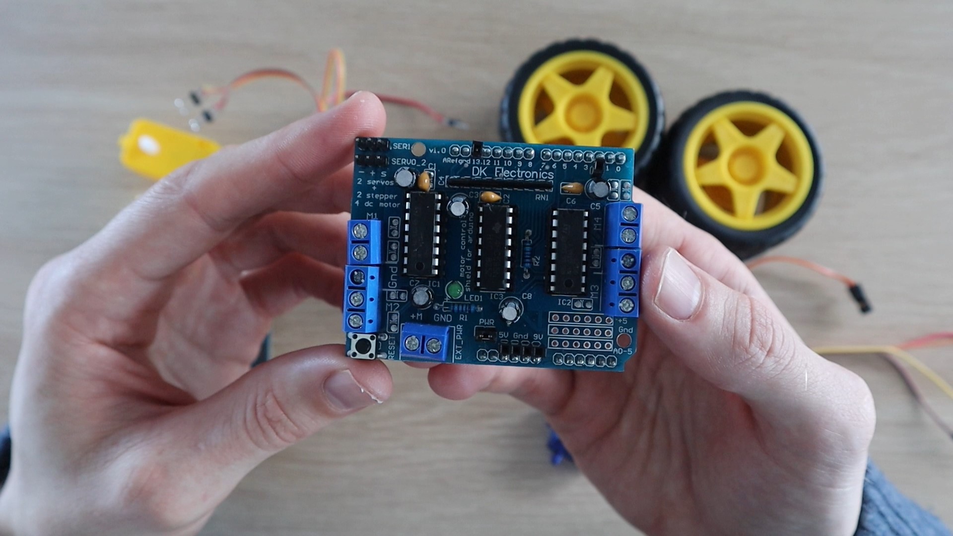
You’ll need to solder some female pin headers to the power pins along the bottom of the shield and one for pin 2 and one for pin 13. Pin 2 you can solder into the breakout hole, pin 13 you’ll need to solder directly onto the back side (top) of the shield’s pins.
The object sensing is done by an ultrasonic sensor that uses ultrasonic sound waves to measure the distance to an object by timing how long it takes the pulse to bounce off of the object and return to the sensor. Because we know the speed that sound waves travel through air, we can use the time it takes a pulse to return to the sensor to calculate the object’s distance using the formula:
Distance = Pulse Time x Speed of Sound In Air / 2
We need to divide by two since the pulse travels to the object and then back to the sensor, so it is traveling twice the object’s distance.
Each of the four wheels on the obstacle avoiding car is driven by a geared DC motor, you will need to attach a short power lead to each with some pins to screw into the terminals on the shield.
Assembling The Car
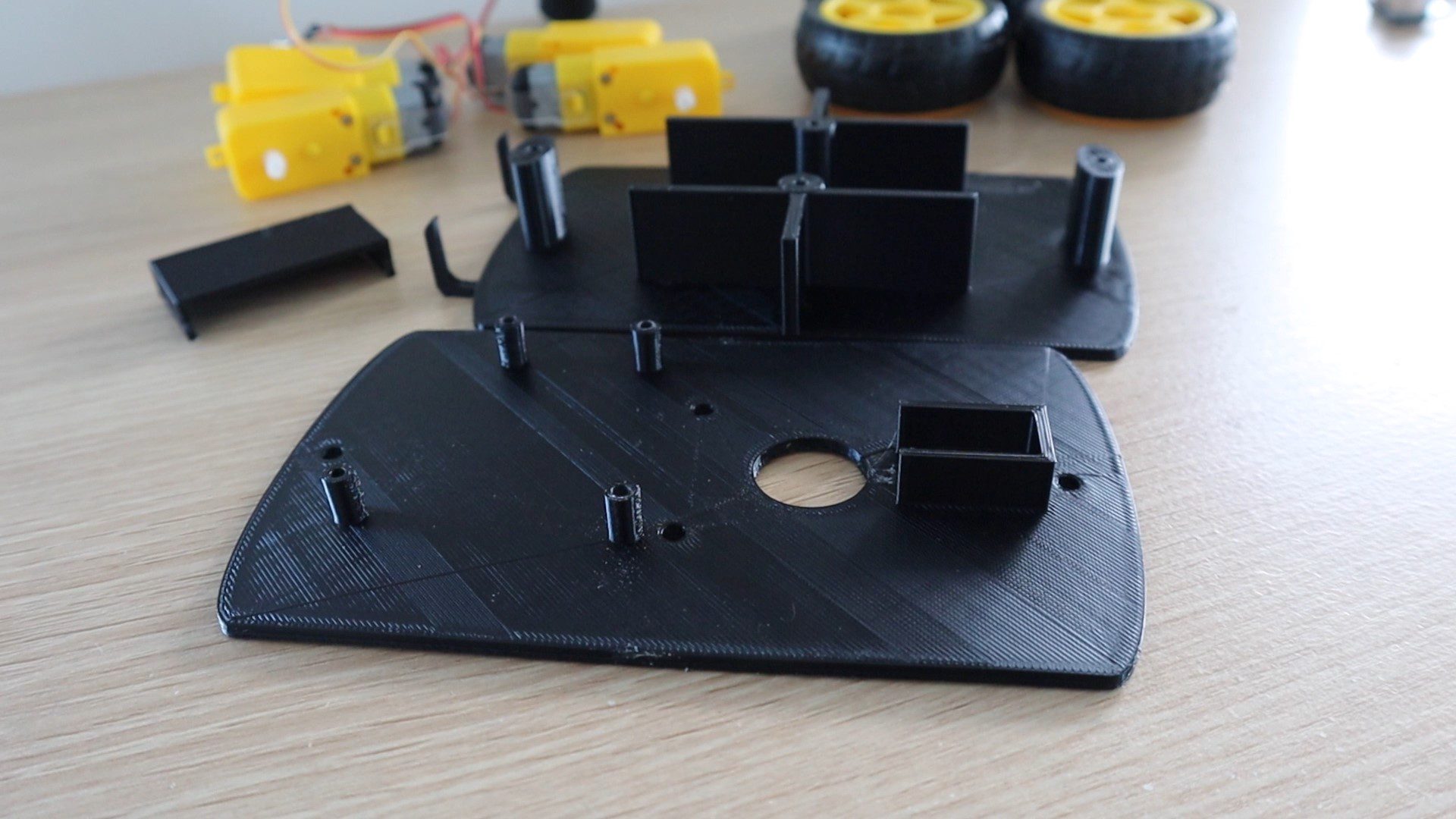
I designed a simple chassis for the car to be 3D printed. I printed mine using black PLA with a 30% infill for the vertical supports.
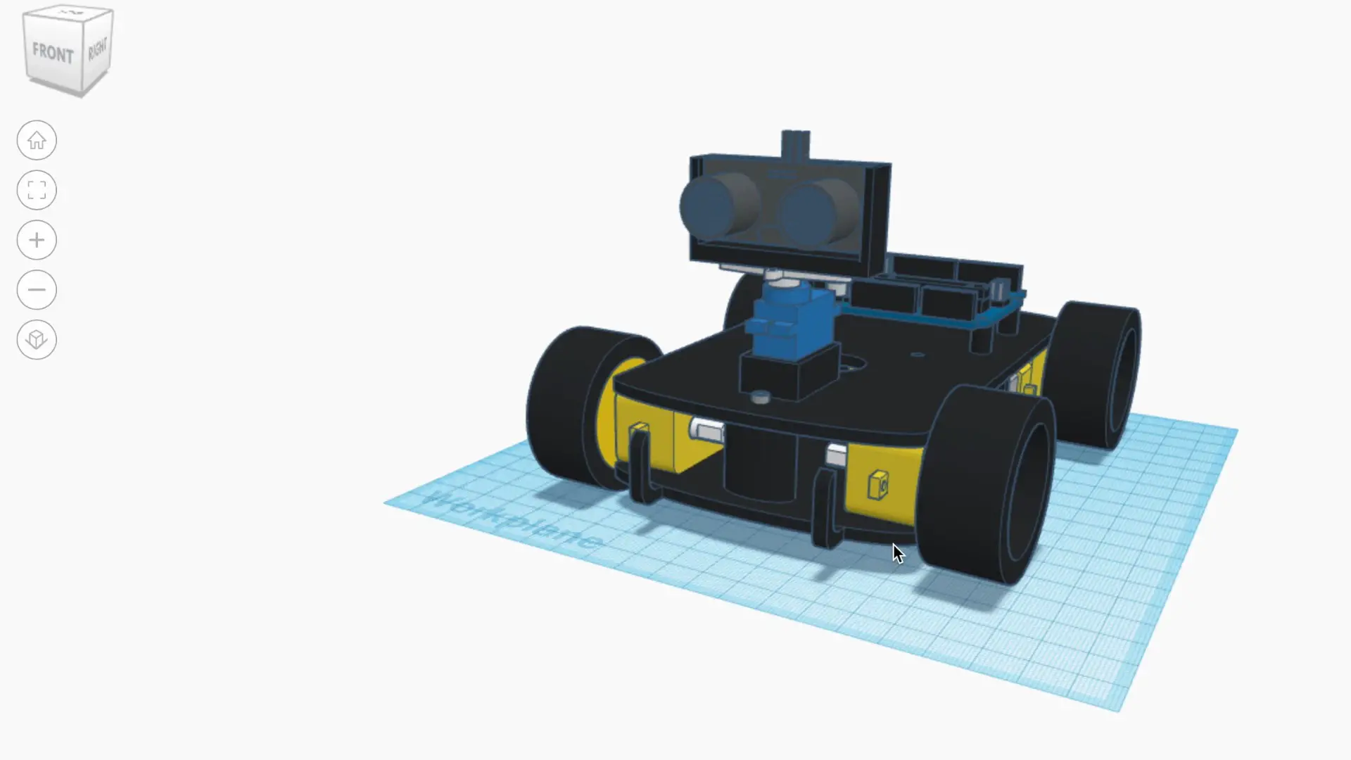
There are three printed components, the top and bottom chassis sections and then a holder for the ultrasonic sensor.
Download The 3D Print Files – 3D Print Files
Once you’ve got all of your components together, let’s start assembling the obstacle avoiding robot car.
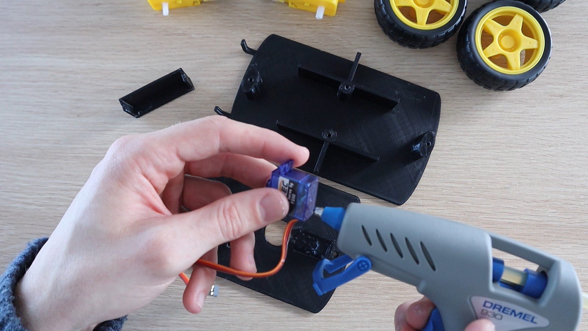
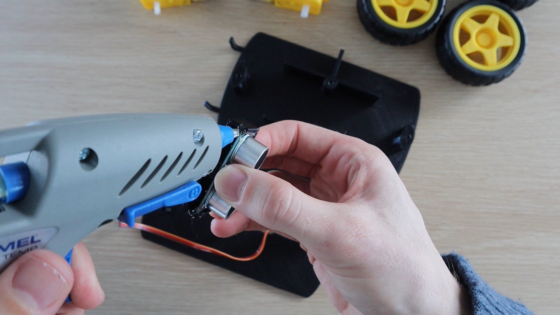
The components are mostly glued into place using a glue gun. Start off by gluing the servo into place with the ribbon cable facing towards the back of the car.
Next, glue the ultrasonic sensor into the housing, making sure that there is some space around the pins for the plug connectors. Then glue the servo arm into the bottom of the holder, so that it can be pushed onto the servo.
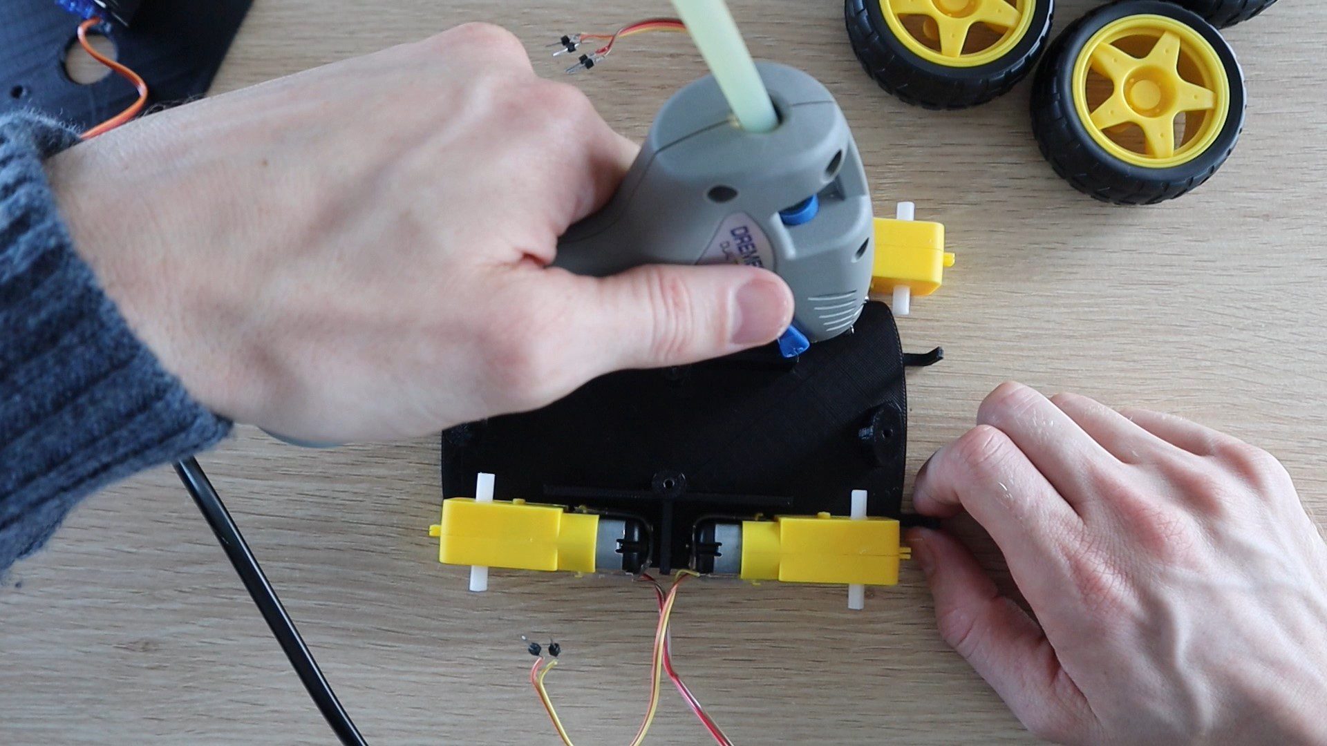
Next, glue the motors into place. Try to keep the wiring to motors on the outside so that you can get to them if any come loose. Don’t worry about the directions that the motors turn, this can be changed by swapping the wires at the shield terminals later.
Glue each motor into place on the bottom chassis plate.
If you are using a rechargeable battery, put the battery into place in the middle section between the motors to free up from space on the top chassis plate. Once the top plate is in place, you won’t be able to get to the battery pack without removing it, so may sure that any leads you to need to get to in order to charge it are available out the back of the car.
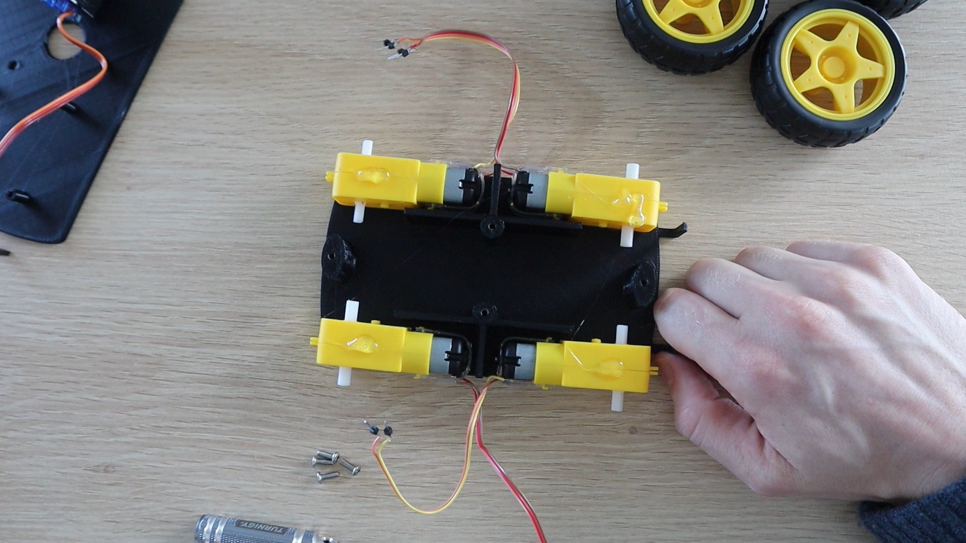
Put a drop of glue onto the top of each motor and then screw the top chassis plate into place.
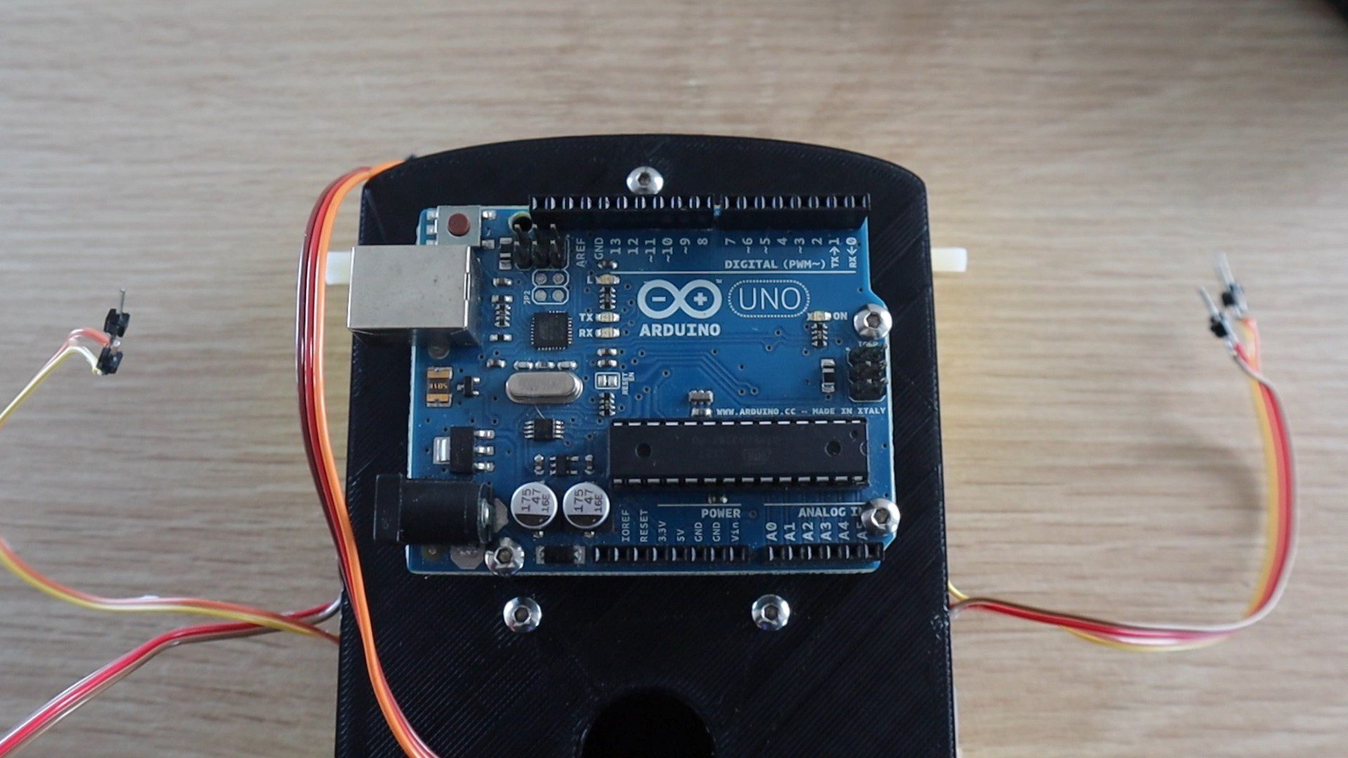
Next, screw your Arduino onto your top chassis plate.
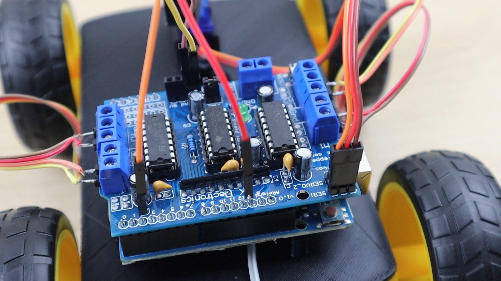
Then plug your motor driver shield into your Arduino.
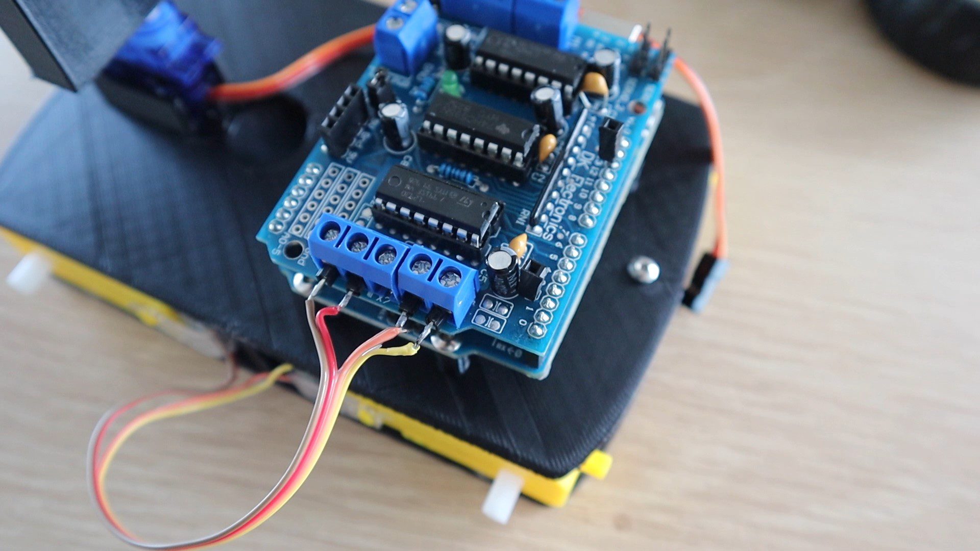
Now screw your motors into each terminal pair. Make sure that each motor is connected to the correct pair of terminals, the front motors to the front terminals, and the back motors to the back terminals. Don’t worry about the polarity of the motors yet, if any turn the wrong way around when you power the car up then simply swap the two wires for that motor around and it’ll then turn the correct way.
Put a drop of glue on the sides of the car to hold the wires away from the wheels so that they don’t get caught up while the wheels are turning.
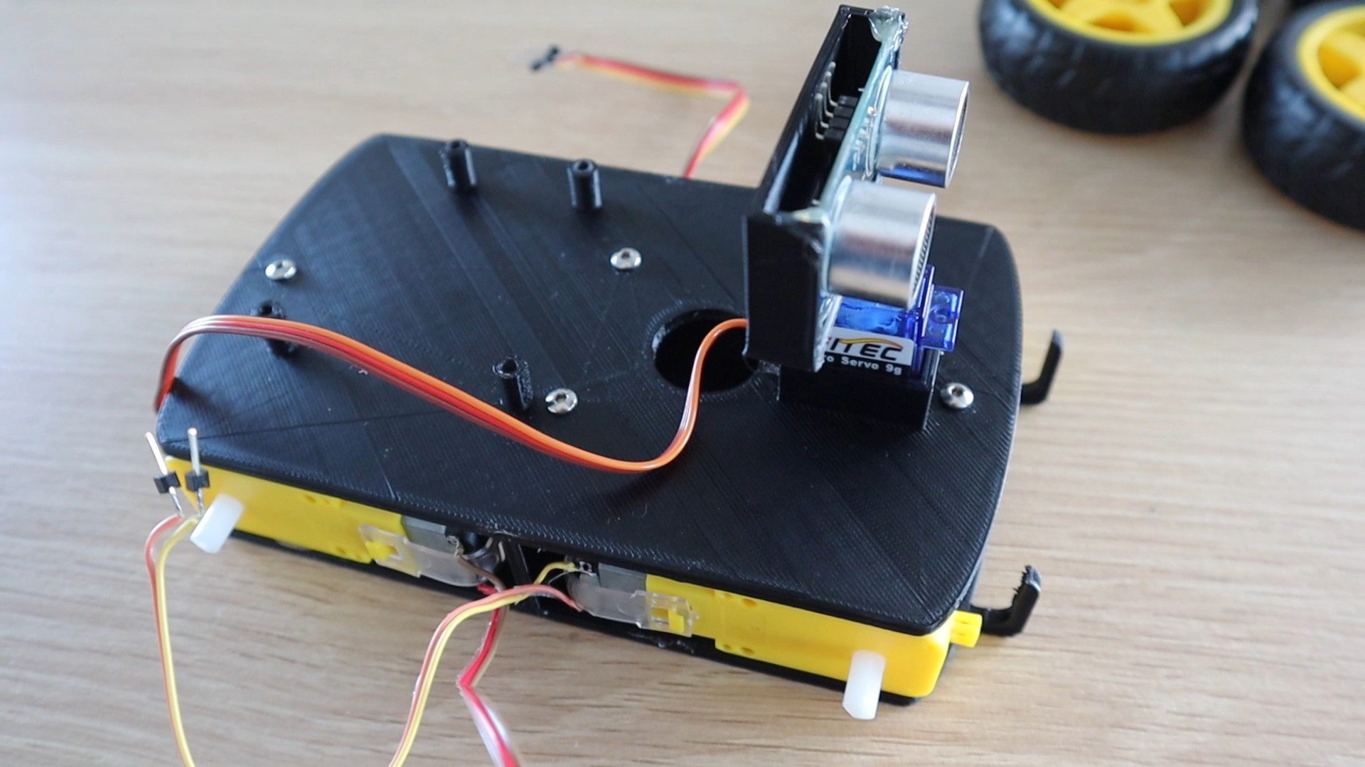
Plug the servo into the servo 1 header pins on the shield with the signal wire facing inwards.
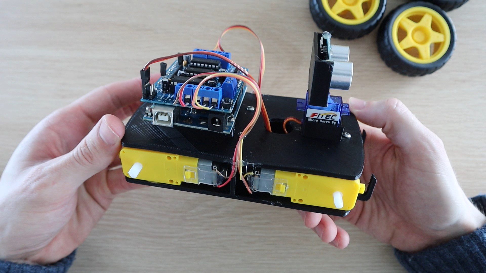
Feed a power cable for your battery in under the board and to the power terminals. If you are not using a rechargeable battery, then place the battery pack into the space between the servo and the Arduino, making sure that it doesn’t get caught on the sensor when it moves.
Important – Don’t plug the battery into the motor shield and a power supply into the Arduino as you’ll damage the Arduino or the shield. Only ever have the battery connected to the shield and feeding power to the Arduino OR the supply plugged into the Arduino (or USB cable) and feeding power to the motor shield.
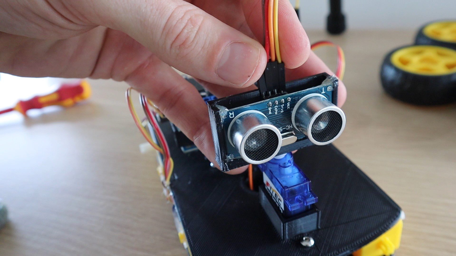
Then plug four wires into the sensor and over to the shield. Plug the ground and Vcc wires into the ground and 5V pins on the shield and then the trigger pin to pin 2 and the echo pin to pin 13.
Lastly, put the four wheels onto the geared motors and the car is now complete.
Programming The Arduino
Now that the obstacle avoiding robot car is complete, let’s have a look at the code.
//The DIY Life
//Michael Klements
//29 June 2020

#include <AFMotor.h>                              //Import library to control motor shield
#include <Servo.h>                                //Import library to control the servo

AF_DCMotor rightBack(1);                          //Create an object to control each motor
AF_DCMotor rightFront(2);
AF_DCMotor leftFront(3);
AF_DCMotor leftBack(4);
Servo servoLook;                                  //Create an object to control the servo

byte trig = 2;                                    //Assign the ultrasonic sensor pins
byte echo = 13;
byte maxDist = 150;                               //Maximum sensing distance (Objects further than this distance are ignored)
byte stopDist = 50;                               //Minimum distance from an object to stop in cm
float timeOut = 2*(maxDist+10)/100/340*1000000;   //Maximum time to wait for a return signal

byte motorSpeed = 55;                             //The maximum motor speed
int motorOffset = 10;                             //Factor to account for one side being more powerful
int turnSpeed = 50;                               //Amount to add to motor speed when turning


void setup()
{
  rightBack.setSpeed(motorSpeed);                 //Set the motors to the motor speed
  rightFront.setSpeed(motorSpeed);
  leftFront.setSpeed(motorSpeed+motorOffset);
  leftBack.setSpeed(motorSpeed+motorOffset);
  rightBack.run(RELEASE);                         //Ensure all motors are stopped
  rightFront.run(RELEASE);
  leftFront.run(RELEASE);
  leftBack.run(RELEASE);
  servoLook.attach(10);                           //Assign the servo pin
  pinMode(trig,OUTPUT);                           //Assign ultrasonic sensor pin modes
  pinMode(echo,INPUT);
}

void loop()
{
  servoLook.write(90);                            //Set the servo to look straight ahead
  delay(750);
  int distance = getDistance();                   //Check that there are no objects ahead
  if(distance >= stopDist)                        //If there are no objects within the stopping distance, move forward
  {
    moveForward();
  }
  while(distance >= stopDist)                     //Keep checking the object distance until it is within the minimum stopping distance
  {
    distance = getDistance();
    delay(250);
  }
  stopMove();                                     //Stop the motors
  int turnDir = checkDirection();                 //Check the left and right object distances and get the turning instruction
  Serial.print(turnDir);
  switch (turnDir)                                //Turn left, turn around or turn right depending on the instruction
  {
    case 0:                                       //Turn left
      turnLeft (400);
      break;
    case 1:                                       //Turn around
      turnLeft (700);
      break;
    case 2:                                       //Turn right
      turnRight (400);
      break;
  }
}

void accelerate()                                 //Function to accelerate the motors from 0 to full speed
{
  for (int i=0; i<motorSpeed; i++)                //Loop from 0 to full speed
  {
    rightBack.setSpeed(i);                        //Set the motors to the current loop speed
    rightFront.setSpeed(i);
    leftFront.setSpeed(i+motorOffset);
    leftBack.setSpeed(i+motorOffset);
    delay(10);
  }
}

void decelerate()                                 //Function to decelerate the motors from full speed to zero
{
  for (int i=motorSpeed; i!=0; i--)               //Loop from full speed to 0
  {
    rightBack.setSpeed(i);                        //Set the motors to the current loop speed
    rightFront.setSpeed(i);
    leftFront.setSpeed(i+motorOffset);
    leftBack.setSpeed(i+motorOffset);
    delay(10);
  }
}

void moveForward()                                //Set all motors to run forward
{
  rightBack.run(FORWARD);
  rightFront.run(FORWARD);
  leftFront.run(FORWARD);
  leftBack.run(FORWARD);
}

void stopMove()                                   //Set all motors to stop
{
  rightBack.run(RELEASE);
  rightFront.run(RELEASE);
  leftFront.run(RELEASE);
  leftBack.run(RELEASE);
}

void turnLeft(int duration)                                 //Set motors to turn left for the specified duration then stop
{
  rightBack.setSpeed(motorSpeed+turnSpeed);                 //Set the motors to the motor speed
  rightFront.setSpeed(motorSpeed+turnSpeed);
  leftFront.setSpeed(motorSpeed+motorOffset+turnSpeed);
  leftBack.setSpeed(motorSpeed+motorOffset+turnSpeed);
  rightBack.run(FORWARD);
  rightFront.run(FORWARD);
  leftFront.run(BACKWARD);
  leftBack.run(BACKWARD);
  delay(duration);
  rightBack.setSpeed(motorSpeed);                           //Set the motors to the motor speed
  rightFront.setSpeed(motorSpeed);
  leftFront.setSpeed(motorSpeed+motorOffset);
  leftBack.setSpeed(motorSpeed+motorOffset);
  rightBack.run(RELEASE);
  rightFront.run(RELEASE);
  leftFront.run(RELEASE);
  leftBack.run(RELEASE);

}

void turnRight(int duration)                                //Set motors to turn right for the specified duration then stop
{
  rightBack.setSpeed(motorSpeed+turnSpeed);                 //Set the motors to the motor speed
  rightFront.setSpeed(motorSpeed+turnSpeed);
  leftFront.setSpeed(motorSpeed+motorOffset+turnSpeed);
  leftBack.setSpeed(motorSpeed+motorOffset+turnSpeed);
  rightBack.run(BACKWARD);
  rightFront.run(BACKWARD);
  leftFront.run(FORWARD);
  leftBack.run(FORWARD);
  delay(duration);
  rightBack.setSpeed(motorSpeed);                           //Set the motors to the motor speed
  rightFront.setSpeed(motorSpeed);
  leftFront.setSpeed(motorSpeed+motorOffset);
  leftBack.setSpeed(motorSpeed+motorOffset);
  rightBack.run(RELEASE);
  rightFront.run(RELEASE);
  leftFront.run(RELEASE);
  leftBack.run(RELEASE);
}

int getDistance()                                   //Measure the distance to an object
{
  unsigned long pulseTime;                          //Create a variable to store the pulse travel time
  int distance;                                     //Create a variable to store the calculated distance
  digitalWrite(trig, HIGH);                         //Generate a 10 microsecond pulse
  delayMicroseconds(10);
  digitalWrite(trig, LOW);
  pulseTime = pulseIn(echo, HIGH, timeOut);         //Measure the time for the pulse to return
  distance = (float)pulseTime * 340 / 2 / 10000;    //Calculate the object distance based on the pulse time
  return distance;
}

int checkDirection()                                            //Check the left and right directions and decide which way to turn
{
  int distances [2] = {0,0};                                    //Left and right distances
  int turnDir = 1;                                              //Direction to turn, 0 left, 1 reverse, 2 right
  servoLook.write(180);                                         //Turn servo to look left
  delay(500);
  distances [0] = getDistance();                                //Get the left object distance
  servoLook.write(0);                                           //Turn servo to look right
  delay(1000);
  distances [1] = getDistance();                                //Get the right object distance
  if (distances[0]>=200 && distances[1]>=200)                   //If both directions are clear, turn left
    turnDir = 0;
  else if (distances[0]<=stopDist && distances[1]<=stopDist)    //If both directions are blocked, turn around
    turnDir = 1;
  else if (distances[0]>=distances[1])                          //If left has more space, turn left
    turnDir = 0;
  else if (distances[0]<distances[1])                           //If right has more space, turn right
    turnDir = 2;
  return turnDir;
}
Download The Sketch – RobotCarSketch
We start by importing two libraries, one to control the motor shield and one to control the servo.
We then create an object for each motor and one for the servo.
We then define the ultrasonic sensor pins and create variables for the maximum sensing distance, the distance before an object to stop and calculate the timeout time to stop the sensor from waiting if an object is further than the maximum sensing distance. The timeout is automatically calculated to account for any adjustments which are made to the maximum sensing distance.
We then create variables for the motor speed as well as one to compensate for one sides motors being slightly more powerful causing the car to slowly turn while driving. If you find that your car pulls left or right while driving in a straight line, then make adjustments to this variable to correct it. Lastly, we have a variable for the turn speed, which is the amount of speed to add to each motor when turning to give the car more turning power as the motors are working against each other to rotate the car.
In the setup function we set the motor speed to the defined motor speed, then disable all of the motors to make sure that they’re off and then assign the servo and ultrasonic sensor pin numbers.
In the loop function, we turn the servo to look straight ahead, then wait for the servo to turn. We then call a function called getDistance to measure the distance of an object in front of the sensor. If no object is within the stopping distance we then start the motors to drive the car forward.
We then continually measure the distance to objects in front of the car every 250 milliseconds until an object is within the stopping distance.
We then stop the motors and call a function called checkDirection to decide whether to turn left or right or turn around.
A switch statement then calls the correct method to turn the car. Because we don’t have any movement sensors on the wheels, we have to turn the car for a certain amount of time before we know that it has turned 90 or 180 degrees. If you make adjustments to the motor speed or the turning speed then you might need to adjust these times up or down until you get a 90 degree turn again.
Now let’s have a look at the movement and sensing functions.
I’ve created an acceleration and deceleration function which ramp up and down the motor speeds. I haven’t used these in this version of the code, but they may be useful for future projects.
We then have two functions to set all of the motors to turn in the forward direction and another to stop all motors and then another two to turn left and right. The turn left and right functions turn the wheels on opposite sides of the car in opposite directions in order to turn the car around. So the car can turn around on the spot without needing any forward movement or a steering mechanism.
We then have two sensing functions.
The first is to measure the distance to an object. This function uses the ultrasonic sensor to send a 10 microsecond pulse out and time how long it takes to return. We can then use this time to calculate how far the object is away from the car.
The second function uses the first and turns the ultrasonic sensor to the left and then to the right, taking measurements in each direction. These measurements are then compared in order to decide whether to turn left or right. The car will always turn towards the direction with more space. If both sides have less space than the stopping distance, then the car will turn around and drive back the way it came. This decision is returned to the main loop as a 0, 1 or 2, which then uses the switch statement to execute the turning.
Let’s upload the code and see how the car works.
Setting Up The Obstacle Avoiding Robot Car
The first thing to do is to check your wheel rotation directions when you first run the code. All of the wheels should be turning in the forward direction when the car first starts moving. If any turn in the wrong direction, swap the motor leads around in the terminals to change the motor direction.
Next check that when an object is detected in front of the car, the servo moves left first and then right. On some servos, the signal direction is reversed which will cause the robot car to look right and then left and to turn towards the closer object rather than away from it.
Next allow your car to drive in a straight line with no objects in front of it. If the car pulls left or right, make adjustments to the motorOffset variable to compensate by increasing or decreasing power to the motors on that side. The offset is added to the motors on the left, so if the car turns to the right, you’ll need to decrease the offset and if the car turns to the left then you’ll need to increase the offset.
Lastly, allow the car to detect and object and then try to turn left or right. The car should turn approximately 90 degrees. If it turns too little then you’ll need to increase the turning times in the switch statement. If the car turns too much then you’ll need to decrease the times.
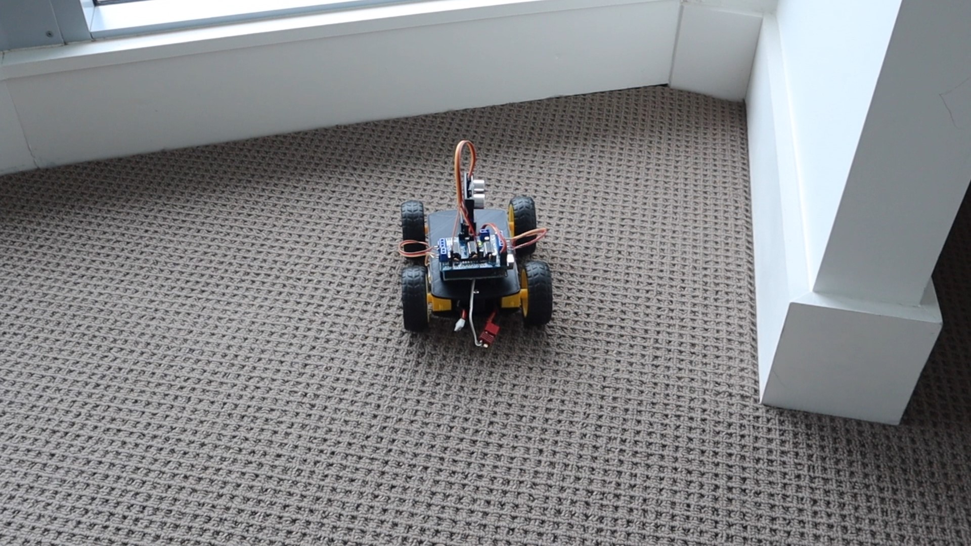
If the car drives into a tight space, it will turn around and drive back out the way it came.
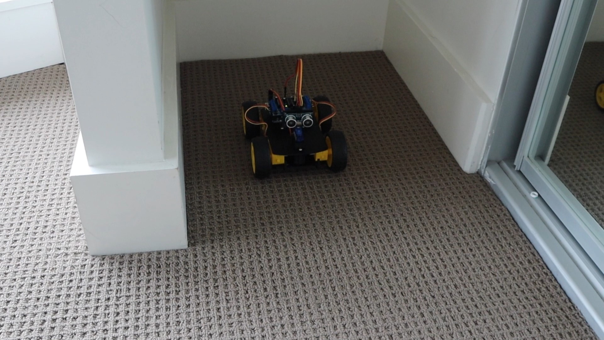
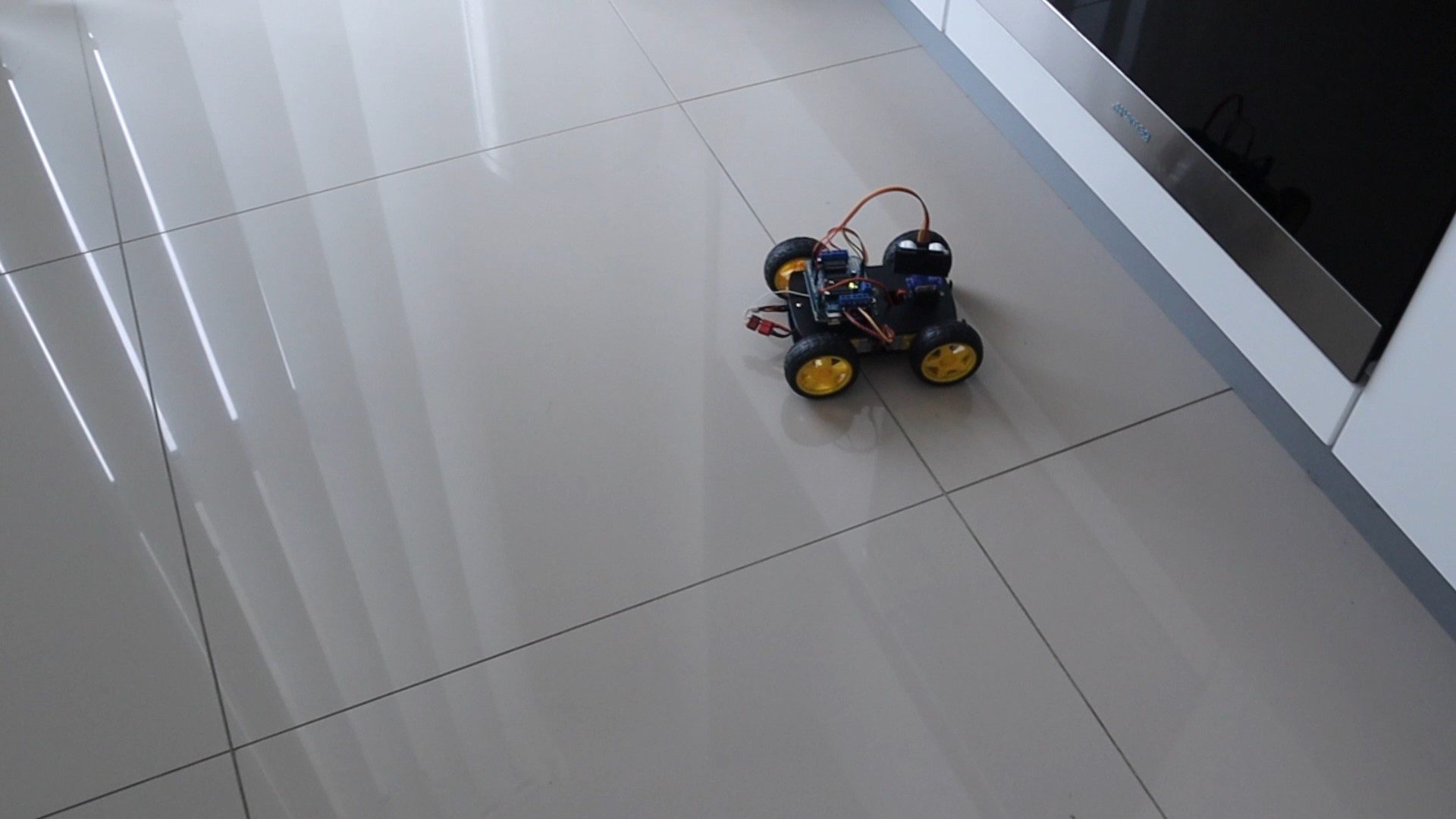
The obstacle avoiding robot car runs well on both carpeted and tiled surfaces as all four wheels are driven. You might need to add a bit extra motor speed on carpeted areas if you find your car has difficultly.
In future, I’ll be adding left and right movement to the ultrasonic sensor during forward movement to detect objects slightly off-center which may come into the robot’s path, and then gently turn the robot car away from them. At the moment if the robot gradually drives towards a slightly off parallel wall, it eventually drives into it and gets stuck because the wall hasn’t come into the sensor’s range. By looking slightly left and right while driving, we should be able to detect this wall slowly getting closer and add some speed to the motors on that side to drive the car away from the wall.
Have you built your own Arduino based obstacle avoiding robot car? Let me know what modifications and additions you made to yours in the comments section.
Share This Guide
Hi
I used the method you used for the project but I am facing a problem. When the robot moves forward all motors run perfectly but when it turn right or left, only the left side motors run. I tried a number of methods, couldn’t detect the bug in code or neither any hardware connection problem. It would a nice help if you could save some time for me.
It’s probably just reducing the one sides motor speed too much. If you hold the car up and move it towards an object, do the motors all turn to make it go left or right? You can most likely correct this using the “turn speed” variable at the beginning. This is an amount added onto the base speed during turning to make sure all wheels turn.
i have upload the code but car dosent move on the ground ,if i take a car in hand all moter are drive.. pls guide me ..
You need to either increase the speed settings in the code or (more likely) your battery pack can’t provide enough current to turn the motors when they are loaded. You’ll need to use a better battery.
Hi Michael, thank you for sharing your wonderful project. How very cool. I’m curious what battery you use in your build? Are you using a voltage regulator of some kind or does the shield regulate? Sorry if this is covered elsewhere. Thanks again for sharing your creation!
sir i make this robot but robot is not strat
Hi Michael,
I’m building my first robot at the moment, the purpose of which will be to patrol my garden to (hopefully) ward off rabbits. Initially I intend to utilise collision avoidance as per your robot and ultimately may include GPS control of its movements. However to get up and running my query is regarding the motor controller. I am using a pair of BTS7960 controllers, one for the two LH motors and the other for the two RH motors. What would be the most straight forward method of adapting your code to work with these controllers instead of the arrangement you have ?. In all other respects this will be identical in functionality to yours. It is confusing me as I will need to apply different commands to control the motors. For each pair of motors I will have two Enable commands (forward & reverse) and two PWM commands (forward and reverse) but I am having difficulty trying to figure out how to incorporate these into your code. This is my very first involvement with code (unless you count learning Fortran at university 30 years ago!!) so any help would be appreciated.
Hi Robin,
This sounds like a pretty cool project to get working! There’s going to be quite a bit of work involved in adapting the code, but it’s structured in much the same way as you’d need for the BTS7960 controllers. The main difference is that the library I’ve used requires an object to be created for each motor (AF_DCMotor rightBack(1) etc.), you are just controlling the motors directly using two pins for each, one for the enable signal and one for the PWM signal for speed. You’ll basically need to change my code so that every time there is a run command (rightBack.run(FORWARD) etc.) you Enable the particular motor, every time there is a stop command (rightBack.run(RELEASE)) you Disable the motor, and then when there is a speed update (rightBack.setSpeed(i)) you set your speed by setting the PWM output on the pin. So your code will work with reference to the Enable and PWM pin numbers for each motor while mine works with sending commands to an object. Other than that the code should be very similar. Hopefully this guides you in the right direction as a starting point?
Thanks Michael,
That clarifies what I need to do. The use of the library was confusing me. I think I can see now how to command the motors to operate via the direct pin functions. It’s not as neat as using the library but will actually be easier for me to understand I think. I’ll have a go at implementing the code and hopefully it will work. Your help is greatly appreciated,
Robin
Hi Michael,
Such a great work from you! I am doing a project at school but I am facing a problem, my servo would not turn any directions whenever the sensor detect something ahead. I hvae tried another servo but still got the same result. Could you have any suggestion for this situation?
Thank you.
Are your servo pin connections correct and are you sure that the pins you’ve soldered are the same number as in the code? Try changing the code to move the servo without any of the other code (put the servo movement into the setup function) and check that you are able to move the servo at all.
Hi Michael, thanks for the help! I’ve found out that the problem came from the Arduino Shield, thanks a lot, it works!
Pls can I change ur name to my name in the programming
In the code it is saying that motor Offset is not declared in this scope.
motorOffset is the second last declared variable. Have you edited the code in any way?
Hi Michael I need to transform my car who is exactly like yours but only with 2 motors in a circuit (in a bread bord) do you think you can help me Pls
Thank you
Sure, are you using the same motor driver shield?
Yes I’m using the same motor shield and one more thing my car will only have two wheels the changes I need to do in the code is delete two motors of the code right
Yes then it should be quite easy to do, you just need to remove either the two front or two rear motors.
Alright that’s all thanks. For the circuit I already did alone but thanks again for your help
Where is the circuit diagram I’m unable to connect motor in a correct manner
Hi Man ,Great project is there a circuit diagram somewhere. I cant seem to find one to download, Thanks PW
I haven’t drawn up a circuit diagram for this project as it’s primarily controlled by the motor driver shield. You just need to plug the ultrasonic sensor and servo into the shield, for which the pin numbers are given.
Hi I am doing an Arduino car for a school project, and I thought that your tutorial was pretty great. I have an HC-05 Bluetooth module, any idea how I can add on to this and make it Bluetooth controlled as well? – Nathaneal
Hi,
I built the robot but when I uploaded the code it only the servo rotated and rest of the components didn’t work
Do you have any solution for this problem?
You will need to do some systematic fault finding to figure out what isn’t working and why. I suggest trying to get each of the components (the sensor, then the servo, then the motors) working individually and then try getting them to work together.
Hey, your project is great! I did everything as you mentioned, except por the soldering in the motor shield, which I couldn’t understand how to put the header pin ahahah.
But, anyways, I’m facing a problem with the connection on pin 13. When I connect the cable it seems to work, but with a slightly little movement I lose everything. When soldering ir directly to the shield, it didn’t work. Do you have any solution?
I did that and I discovered that all the motors didn’t work with servo and the ultrasonic I can’t determine why but every motor worked individually.
If all of the components work individually but not together then you’ve probably got a power supply problem. Try using a more powerful battery pack or temporarily powering it with a 12V mains supply.
Hello, Michael .
I build my Robot Car Using same Code and all connections same all is Working perfectly .
I launched my YouTube Channel about Two weeks ago and I’m not sure if I could upload the the Video and add it to my Videos I make of how to make your own obstacle avoiding robot car. I saw different projects similar to your project in Youtube but I did my avoiding robot car base on your Code and Connections .
I thank you in advance Michael!
Hi Isidro,
That’s great. Yes, you can upload your build video, just make sure that you credit this post as the original source of the instructions and code.
Good luck with your channel!
I Michael, I have a problem, when I run the program, arduino beeps. I had to research and they said is the battery, is true? Tks
Hi Michael,
I’ve built the car to your specs but the problem I have is that the wheels (motors) on the left side don’t engage, I’ve checked the motors are okay by moving the wires to the right side of the shield. There just seems no power getting to the left side of the shield, would you have any ideas.
Many Thanks
Try adjusting the motor speed in the sketch
Hi Michael I just receive my motor sheild and I tried to program the code but it give me a error AFMotor.h:No such file or derectory
I didn’t plug in the servo,motors or sensor yeath, but should program I think.
You need to install the required libraries for the code to compile.
hahaha
Hey Michael,
I set up everything right but motor 1 does not react to the speed in code, it just runs at default speed. How to fix that?
Check your wiring and make sure that nothing has been changed in the code to override this motor’s setup/control. It also might be related to the offset parameter, so try adjusting this.
Hello, Sir
i have a problem that robot turn in that side where that distance is less but according to you it should turn where distance is more .how to fix that pls tell?
You’ve probably got the wheels connected opposite to what I had. Swap your left and right motor connections around or try changing the assignment in the code so that left becomes right and right becomes left.
hey, I’m not sure what’s the problem but instead of actually doing something my Arduino or something it just beeps. I thinks its the motors causing this.
Either your battery isn’t able to supply enough current to drive the motors or the speed setpoints in the code need to be increased to tell the driver chips to supply more power to the motors.
Hello Sir, You said earliar in the post “In future, I’ll be adding left and right movement to the ultrasonic sensor during forward movement to detect objects slightly off-center which may come into the robot’s path, and then gently turn the robot car away from them.”
If you have added that code, please share me the link.
Regards
I haven’t gone any further with this code at this stage.
There was same problem with me, I increased the motorSpeed, it solved my problem. Thanks Honourable Michael Klements.
Hi Micheal
I hope you will be near to response
Im using arduino mega with the same l293 shield
The proplem is when there is no object infront of the car the the motors make a sound like a tone and it Just works when I move it with my hand
I hope you understand me, my english is not that much
Thanks.
Hi Michael
I’m doing the same, thanks… is the position of the servo as shown in the photos an angle (0) ?
Thank you very much
Hi Michael,
Thanks for the work, please tell me, do the servo angles run to the right (0-90-180)?
Thank you very much
Hi Michael,
Nice work. But I don’t have 3D printer yet. Can I order from you ? thanks.
Yan
can you please help me to install library. I tried still gave me error
can you please help me to install library. I tried still gave me error
The library to install is this one: “Adafruit Motor Shield”
I installed v.1 and v.2. You don’t need to know more than that, but you can read more about it here: https://learn.adafruit.com/adafruit-motor-shield/using-dc-motors
Hello! I’ve tried the code you posted here, but it says “AFMotor: No such file or directory”. I don’t have knowledge about coding but I really need this for my project. I don’t know what’s the problem and how to solve this. I hope you can help me. Thank you very much!
You need to install the AFMotor library. This is available through the link mentioned after the code.
hi sir please help me in sloveing this error
Arduino: 1.8.16 (Windows Store 1.8.51.0) (Windows 10), Board: “Arduino Uno”
obstical_A:15:1: error: expected ‘,’ or ‘;’ before ‘byte’
byte motorSpeed = 55;
^~~~
C:\Users\Documents\Arduino\obstical_A\obstical_A.ino: In function ‘void setup()’:
obstical_A:21:22: error: ‘motorSpeed’ was not declared in this scope
rightBack.setSpeed(motorSpeed);
^~~~~~~~~~
C:\Users\\Documents\Arduino\obstical_A\obstical_A.ino:21:22: note: suggested alternative: ‘turnSpeed’
rightBack.setSpeed(motorSpeed);
^~~~~~~~~~
turnSpeed
obstical_A:30:11: error: expected unqualified-id before ‘(‘ token
pinMode.(trig,OUTPUT);
^
obstical_A:31:11: error: expected unqualified-id before ‘(‘ token
pinMode.(echo,INPUT);
^
C:\Users\Documents\Arduino\obstical_A\obstical_A.ino: In function ‘void loop()’:
obstical_A:50:17: error: ‘trunDir’ was not declared in this scope
Serial.print(trunDir);
^~~~~~~
C:\Users\Documents\Arduino\obstical_A\obstical_A.ino:50:17: note: suggested alternative: ‘turnDir’
Serial.print(trunDir);
^~~~~~~
turnDir
obstical_A:55:15: error: expected ‘;’ before ‘:’ token
break:
^
obstical_A:55:15: error: expected primary-expression before ‘:’ token
C:\Users\Documents\Arduino\obstical_A\obstical_A.ino: In function ‘void accelerate()’:
obstical_A:64:19: error: ‘motorSpeed’ was not declared in this scope
for (int i=0; i<motorSpeed;i++)
^~~~~~~~~~
C:\Users\Documents\Arduino\obstical_A\obstical_A.ino:64:19: note: suggested alternative: 'turnSpeed'
for (int i=0; i Preferences.
It looks like you’ve got a missing “;” somewhere near the beginning of your code.
Hi, Sir Ca you give me the servo.h file please
Sir I am making obstacle avoiding car but the servo in this project just turns into 360° which turns the jumper connected to ultrasonic sensor. Now what can I do sir?
Make sure that the servo is connected to the correct pin. Can you control it by adjusting the code? Try getting the servo working by itself first if it is causing trouble.
Hi , Michael … I’m working on similar project but using raspberry pi zero and L293D… I’m trying to employ your project’s idea into building my own lawn mower.
My issue is how to get a driver for all four motors which is not bulky
Have a look at brushed dc motor drivers for RC cars, they’re relatively cheap and compact.
can I use the same LIDAR sensor instead of ultrasonic sensors ?
Hi Michael my robot’s wheels are not working properly. All 4 wheels moves when the car is going forward but when it needs to turn, only the right wheels move. I have tried increasing the motor and turn speed in the code but that did not help. I think it might be that my car does not have enough voltage from the 9v I used. the volatmeter said that my battery only had 8.2 volts. I am going to increase the voltage to 12v and see if that helps. If you have any idea what the the problem is, let me know.
Hi can you please send me the AFMotor.h file
hi Micheal,
May I know how to connect with ESP32. How do I set the pinout from ESP32. Appreciate your help.
AF_DCMotor rightBack(1); //Create an object to control each motor
AF_DCMotor rightFront(2);
AF_DCMotor leftFront(3);
AF_DCMotor leftBack(4);
Hi Michael, I have built your Obstacle Avoiding Robot Car. Everything works, except, the motor speed is very low and I dont know how to fix it, I have used two 3.7v 18650 batteries in series creating 7.4v and I didnt modify the code. Can You please help me?
Hi Michael, The code is excellent and works properly and nicely, but I’m currently facing quite a big problem. Everything works, but the motor speed are very low, I am using two 3.7v 18650 batteries in series creating 7.4v, any solution?
HI
I TRIED THIS PROJECT LAST YEAR BUT IT TURNED OUT TO BE FAILURE
AS I TOOK 4*9V BATTERY WHICH CAUSED SHORT-CIRCUIT
CAN YOU SUGGEST WHICH TYPE OF BATTERY IS REQUIRD FOR THIS
PROJECT AND HOW MUCH VOLT BATTERY AND POWER COMSUME BY EACH PART
PLEASE REPLY FAST AS I HAVE MY exhibition ON NOVEMBER
THANK YOU
FROM INDIA
I build this project and downloaded your sketch but here are the errors darning compiling:
redefinition of ‘AF_DCMotor rightBack’
AF_DCMotor rightBack’ previously declared here
Compilation error: redefinition of ‘AF_DCMotor rightBack’
There were more errors, but this website marked it as a spam, so I could”t pastem all here or the location on my Cdrive….arduino…
Do you have a working sketch?
I’m using Arduino IDE version 2.3.2
Nice project. I ordered everything, can’t wait to start. Wich battery are you using? do you have a link?
I built this, thank you for the guide. Some information which might be useful to others building this –
1. I needed a 9V battery to get all wheels turning properly (even a 7.6V 18650 didn’t work very well)
2. The main issue I had (that took some debugging) was motor speed. For some reason, lower values like 50 for speed do not work with the standard yellow DC gear motors I have. I had to use 255 as MAX_SPEED
3. This guide works well for the hardware side of things but there’s better software (code) which you can use with this implementation. I had more luck using code from a Youtube video I found here https://www.youtube.com/watch?v=1n_KjpMfVT0. There’s a link to the code in the description of the video.
Cheers.
I am trying to upload the code but there is an error popping up saying that,”AFMotor.h:No such file or directory” is there some file directory to be downloaded if yes can u help me in downloading those?
This sounds super cool! I’m imagining all the fun of building it. How do you think the soldering part will go? Any tips for a beginner like me? 😜
This is so cool! I love how it can turn on the spot. Have you tried building one? What was the trickiest part for you?
how did you connect the wires to the motor