In this guide, I’m going to be showing you how to build an automatic plant watering system using a Micro:bit and some other small electronic components. The Micro:bit monitors the moisture content of your plant’s soil using a sensor and then switches on a pump to water it once it gets too dry. This way, your plant is always looked after, even when you’ve forgotten about it or you’re away.
If you like this project, then you might also want to have a look at my smart indoor plant monitoring base, which is made using an Arduino.
Here’s a video of the build and the Micro:bit watering the plant, read on for the full step by step instructions:
What You Need To Build Your Micro:bit Plant Watering System
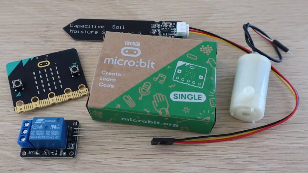
- MicroBit – Buy Here
- Capacitive Moisture Sensor – Buy Here
- DC Pump – Buy Here
- Relay Module – Buy Here
- Ribbon Cable – Buy Here
- Storage Containers (Not the same, but should work) – Buy Here
- Power Supply – Buy Here
- M3 Screws – Buy Here
I’ve used the MicroBit version 2, but this project can be made using the first version as well.
How To Build Your Micro:bit Plant Watering System
MicroBit is a small, programmable microcontroller, which has a number of onboard sensors and buttons, making getting started with programming really easy.
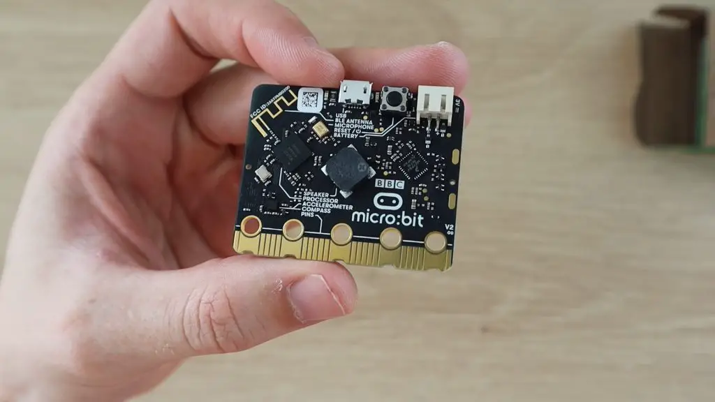
It supports the use of block coding for children and less experienced programmers, and JavaScript or Python for those more experienced with programming and want to access additional functionaliy. It also has a range of IO pins available for sensors and devices along it’s bottom edge.
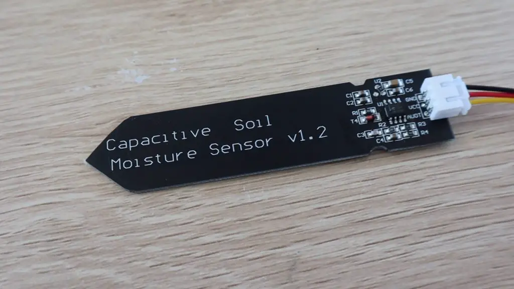
The capacitive moisture sensor that I’m using runs on 3.3V, which is perfect to be used directly with the MicroBit.
Note: These capacitive sensors generally state that they operate between 3.3V and 5V, and output a maximum of 3.3V as they have an onboard voltage regulator. I’ve found that a lot of the cheaper versions of these sensors don’t actually work with an input voltage of 3.3V, but require 3.5-4V before they actually “switch on”. You’ll need to be careful with this as the Micro:bit is only designed for an input voltage of up to 3.3V.
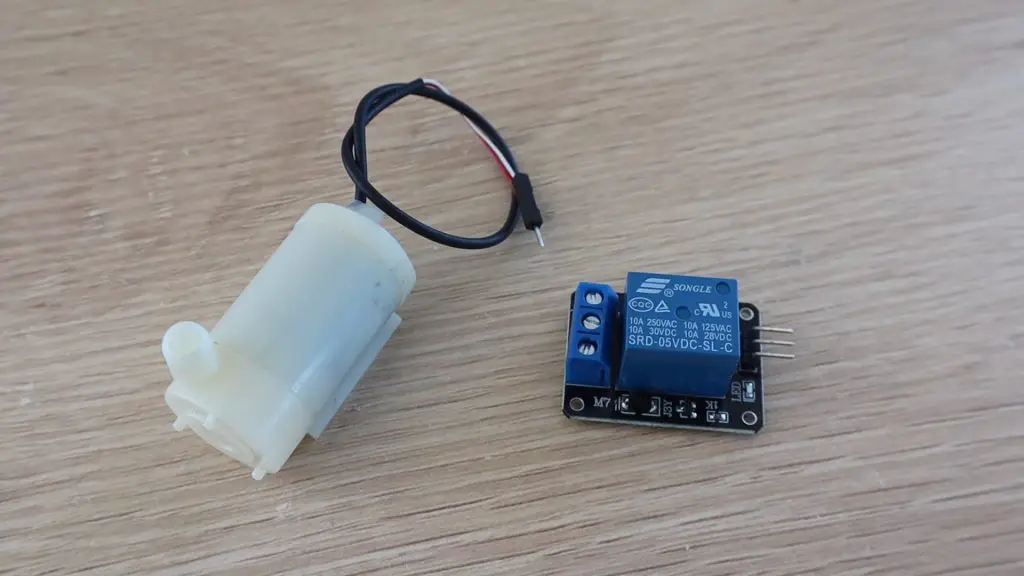
The pump will need to be turned on and off using a relay module. The relay module switches power to the pump so that current isn’t flowing through the MicroBit.
Designing The Circuit & Block Code
I’ve designed the circuit and did the block coding in TinkerCAD, since they’ve recently added the MicroBit to their platform. Block coding is a really easy way to build basic programs by just dragging and dropping function blocks.
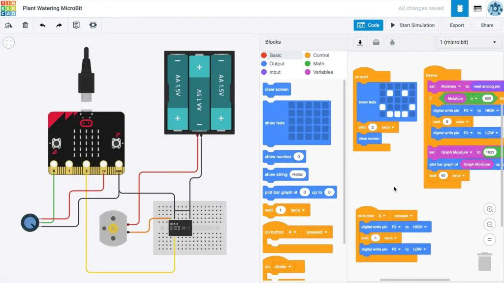
I represented the pump with a DC motor and simulated the input from the moisture sensor using a potentiometer as this has the same three connections as the moisture sensor.
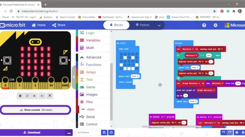
Here is a version of the code from the MicroBit editor.
You can also use the online MicroBit editor on the official MicroBit website if you’d like. This version has a bit more functionality on the block coding side but is more limited in what you can do with circuit design.
My final version of the block code shows a smiley face when it’s turned on then starts taking moisture readings every 5 seconds and plotting them on the graph on the display. It also checks whether the level is below the set limit, and if it is, then it turns on the pump for 3 seconds.
I also added functions to the two buttons where button A turns the pump on for 3 seconds to manually water the plant and button B shows the raw moisture level reading taken from the sensor so that you can easily establish your setpoint level.
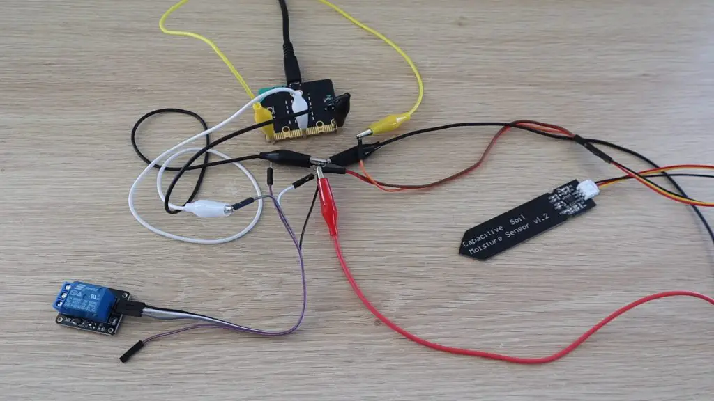
Once I had designed and simulated the program, I connected the components using alligator leads to test that it all worked correctly on my desk. This was to check that the input from the moisture sensor was being read correctly and that the relay switched on and off.
Building The Components Into The Housing
Once I was happy with the test setup, I got to work on building the components into a suitable housing and doing the permanent electrical connections.
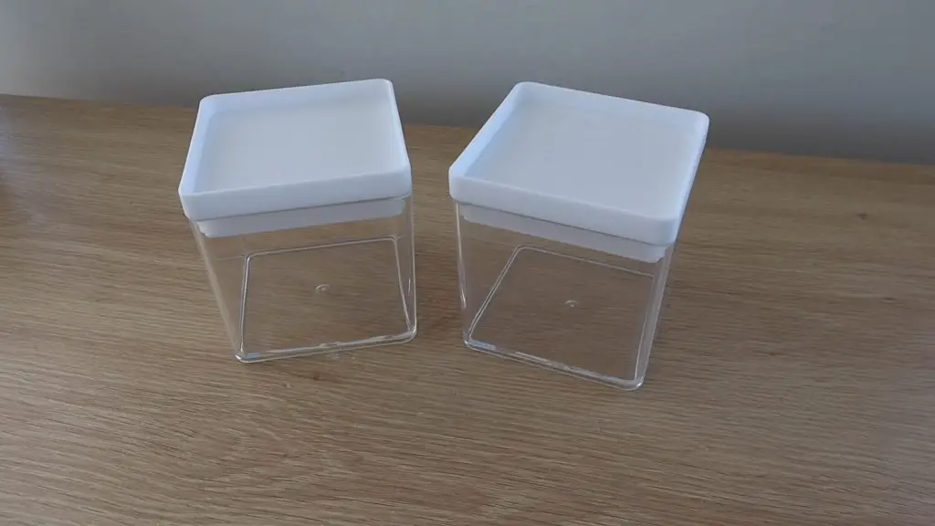
I found these two containers in a local discount store. They stack together so that I could use the bottom one as a tank and the top one to house the electronics. I couldn’t find the exact ones I used on Amazon, but I’ve linked to a similarly sized set with a hinged lid which should work just as well.
Building The Water Tank
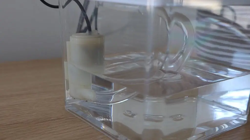
I started by building the tank.
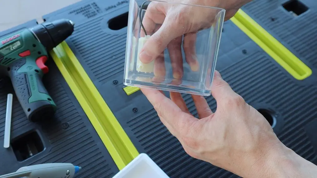
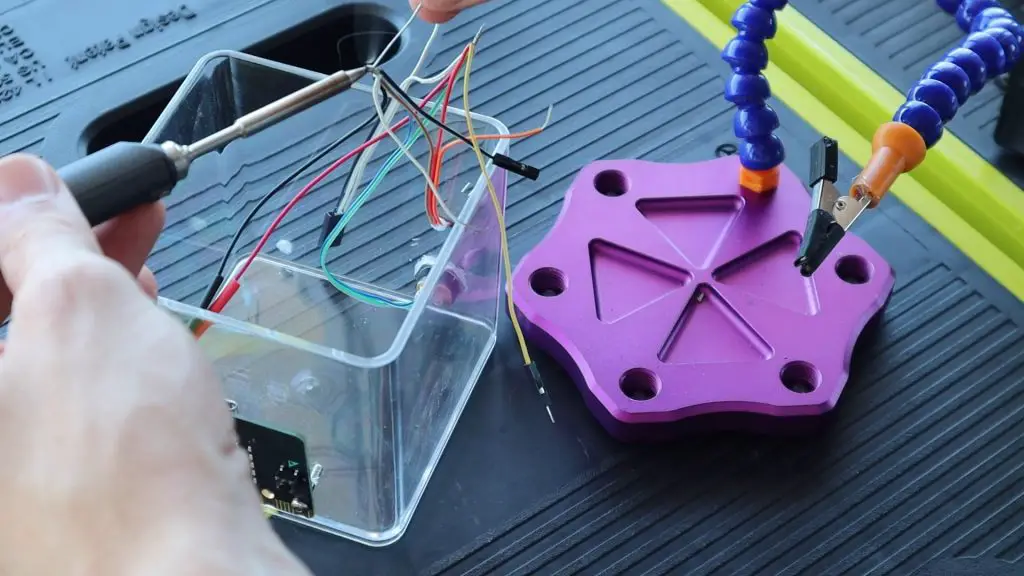
I needed to mount the pump into the tank with the water inlet as close to the bottom as possible, making sure that there was still enough space for the water to flow. I just glued the pump in place using a glue gun.
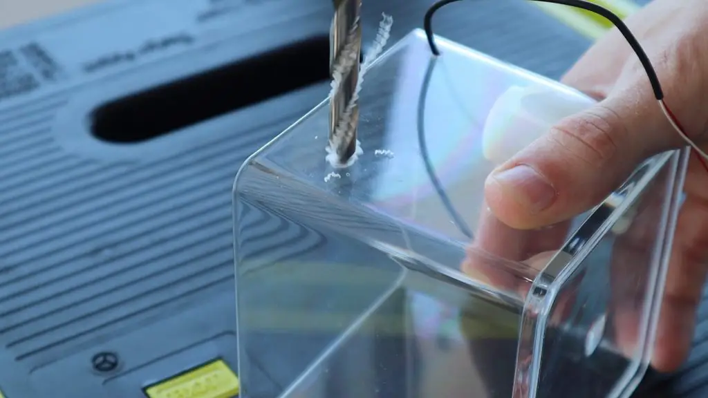
I then drilled holes for the wires to the motor and the tube for the water outlet.
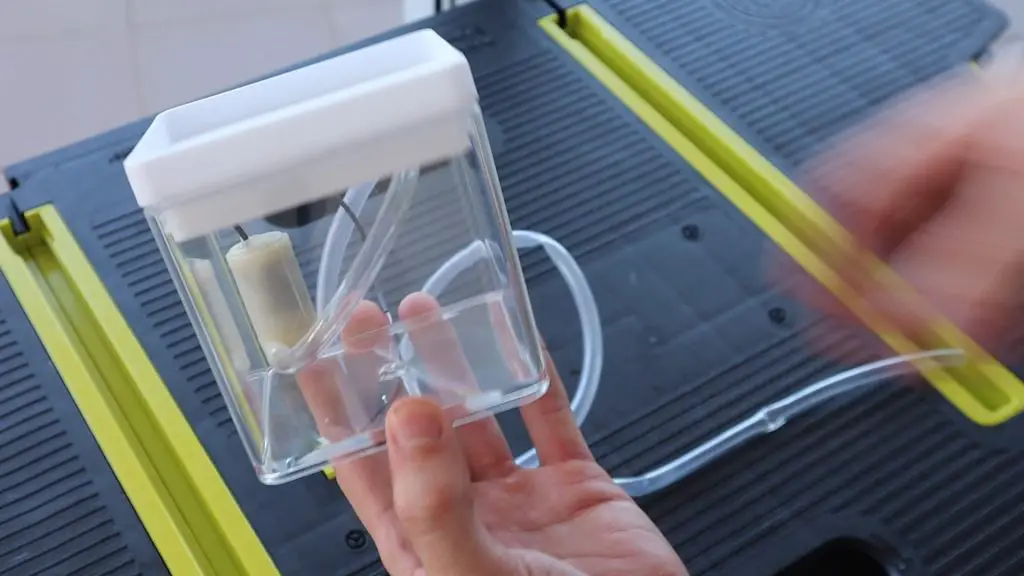
Now that the tank is complete, we can start with the electronics housing.
Assembling The Electronics Housing
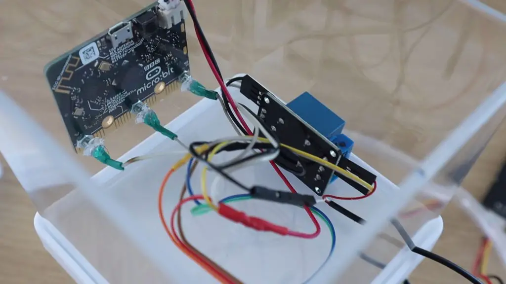
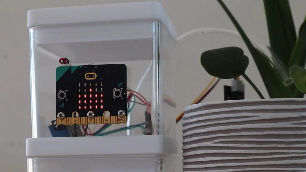
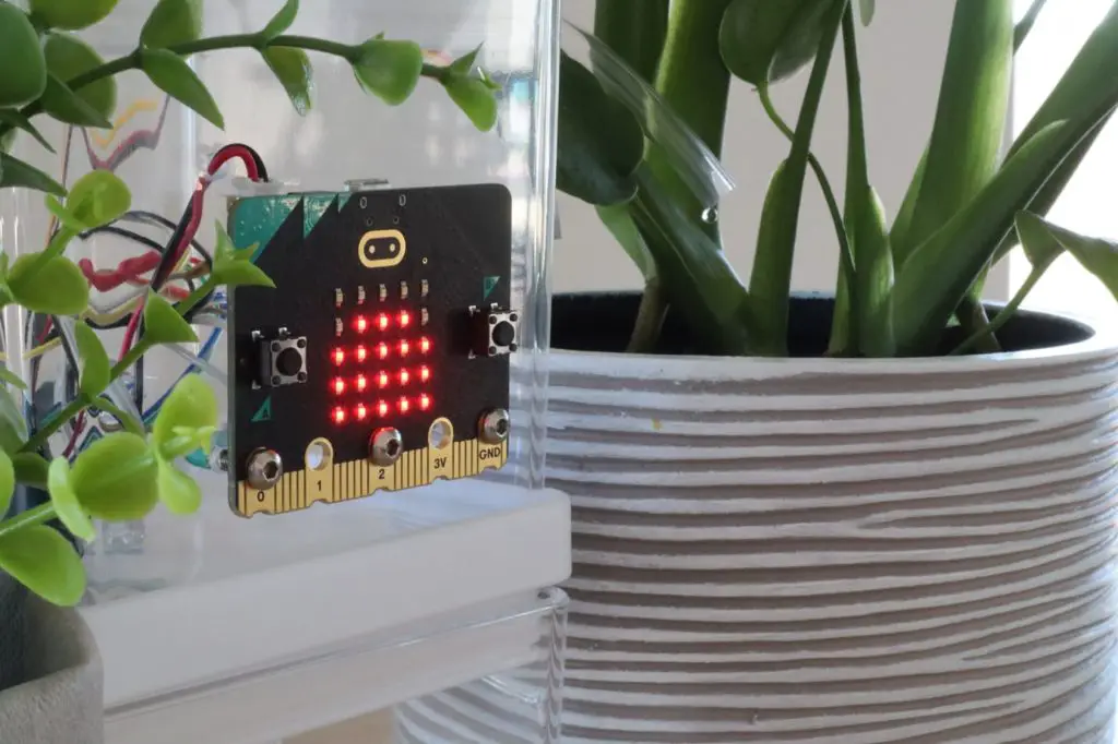
I wanted the MicroBit to be mounted onto the front of the housing so that it’s easy to see as I’m using the LED display on the front as a graph of the water level.
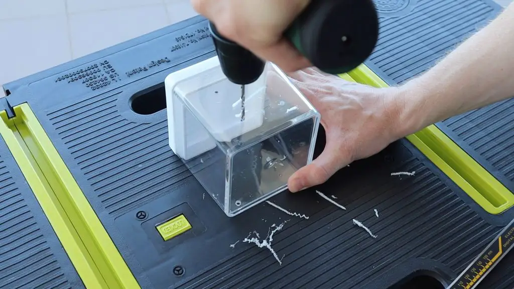
So I drilled three 4mm holes through the front to hold the MicroBit and act as the connections to the IO pins which go through to the wiring on the inside of the case. I also drilled an additional hole above the Micro:bit for the power lead.
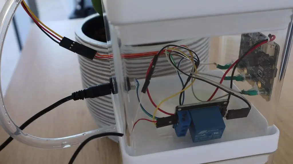
I then drilled holes for the power socket at the back and for the pump and moisture sensor wiring.
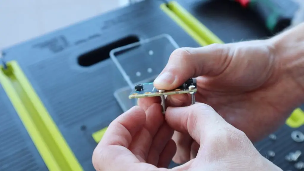
I used a long M3 x 20mm button head screw on each of the 3 pins I needed to connect to, Pin 0, Pin 2 and GND. I connected the wiring to the back of these screws by wrapping the exposed wire around the threads and then using some heat shrink tube to hold it in place.
I then added all of the wiring and connected the components together inside the housing using the same layout as I had tested on my desk.
Using The Micro:bit Automatic Plant Watering System
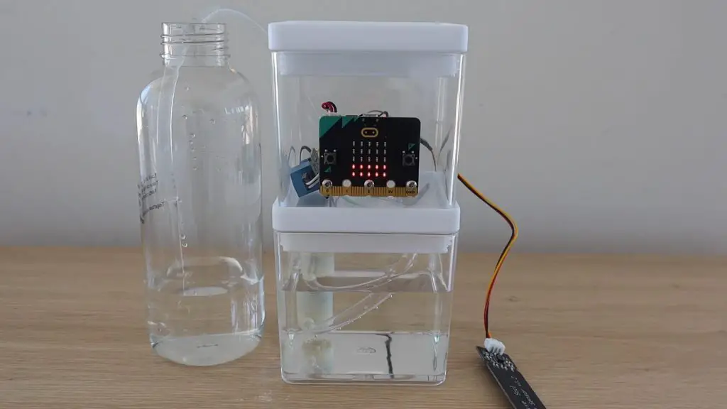
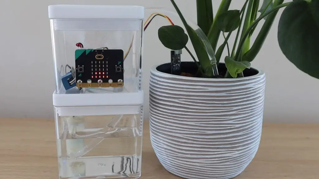
Now that the plant watering system is assembled, we can fill the tank with water and try it out.
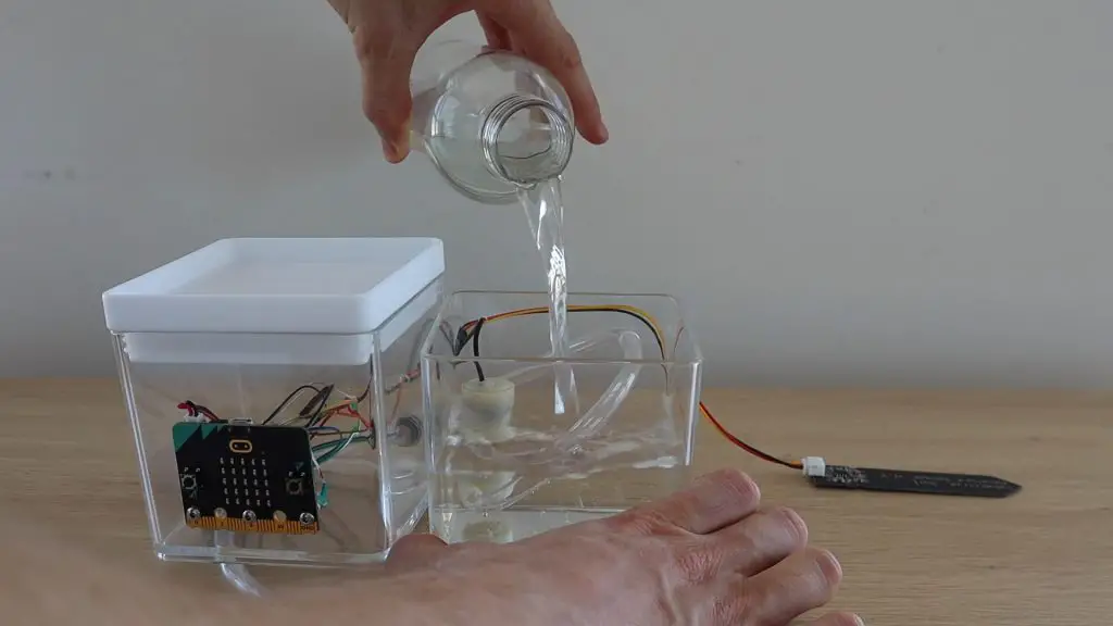
With the sensor out of the soil, it immediately sensed that the “soil” was dry and turned the pump on, so it looks like it’s all working correctly.
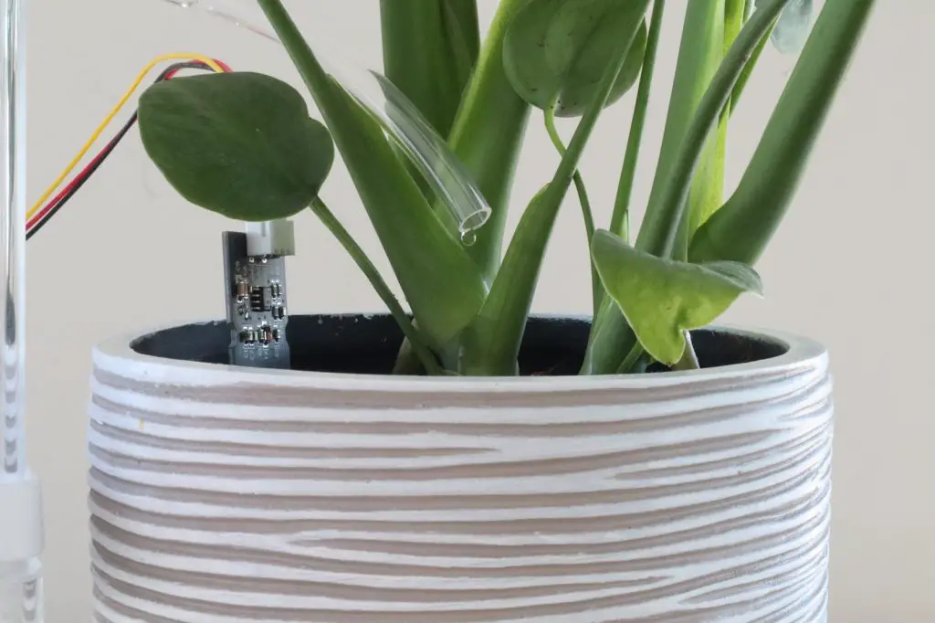
I then pushed the sensor into the soil on one of my indoor plants and positioned the water tube over the soil before switching it back on again.
The graph on the front shows the moisture level which has been measured by the sensor as the soil dries out.
When it gets below the threshold set in the code, the pump comes on automatically in 3-second intervals, waiting for 5 seconds between each pumping cycle, until the moisture level goes above the threshold again.
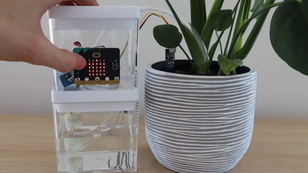
You can also press Button A on the front of the MicroBit to turn the pump on for 3 seconds and water the plant manually.
You could use chain multiple MicroBits together using their radio link to view your plant’s moisture level from a different room or even water them remotely. This would be great if you had a couple of plants being cared for using Micro:bits, and you wanted a single one to act as a dashboard in a central location.
Have you used a MicroBit for one of your projects? Let me know what you built in the comments section.
Hello Miacheal, could you please help with the connections/wiring scehmatic diagram please.
The wiring is done the same way as the TinkerCAD layout
oh ok… I saw your reply now. Thanks for the reply. ok Let me follow that CAD layout.
Thanks again.
Sorry, I am new to TinkerCAD. I couldn’t find the link … I tired every key word.
Is the link in your post? Or video? Could you repost in this discussion thread?
Hi Doug,
I’m not sure what you’re looking for a link to?
Hello Please Send me the Wiring Diagram for the project. I have all the components but need help with schematic of the wiring done. Please Assist. Thanks
great now i have a good grade at school
how to make the pump workable please illustrate with a diagram thank you
The circuit diagram alongside the Tinkercad example shows how to connect it. The motor is representative of the pump.
Michael, as you can see a lot of us have trouble understanding the circuit. please make a clean circuit diagram and upload it here. Thank you.
Hi Micheal, I noticed a problem while testing. When the humidity condition becomes false, the relay remains hooked to the current active state. This means that the pump keeps sending water even when the humidity is below the target value. Your help will be greatly appreciated.
Hi Sunny,
The relay latching is time-based, it doesn’t monitor the moisture content while watering because there is a delay in the water being absorbed into the soil. So when the soil dries out, the relay/pump is turned on for a few seconds to water the plant and the moisture monitoring only starts up again after the watering cycle.
Hi Michael,
I was wondering how you powered your system, because I don’t think it will last very long on batteries, did you use a 3v power supply? If you did could you link it please, Thank you.
Sorry I just saw the link on your video.
Puedo controlar la bomba por radio usando 2 micro bit?
Hi do you dell he system please ?
We are using the same pump, but a different relay from takimizawa. The relay is not bipolar. It has a 3VDC coil. We are afraid, that the microbit is overloaded with the current through the coil, which is 64 mA.
What is the maximum current you can draw from the mirobit without using a separate powersource? Thanks for responding
You can’t drive a relay coil directly with the Microbit’s IO pins, they’ll likely only be able to supply 5-10mA as they’re not intended to “power” devices. You can draw up to 90mA from the 3V pin.
Hi, I was wondering how the 5V relay can be activated by the 3V power supply?
Dirk
can you sent me a whire connection
Hello, I have a question about your Micro:bit Automatic Plant Watering System. I live in Albania and here it’s a bit hard to find all the components, I can’t find a power supply with output 3V : 1A, but I have found one with 0.5-4.2V : 0.5A. Can it work with it?
Hello, I have a question about your Micro:bit Automatic Plant Watering System. I live in Albania and here it’s a bit hard to find all the components, I can’t find a power supply with output 3V : 1A, but I have found one with 0.5-4.2V : 0.5A. Can it work with it?
Hi, I was wondering how it works that the 5V relay switches if your powersupply only delivers 3V?
Greetings
Hi, how can the 5V relay work if the power being supplied is only 3V?
Greetings
Hi, I was wondering how how the 5V relay can be activated by a 3V power supply?
Cheers
Dirk
Hi, I don´t understand how the 5V relay can be activated by the 3V power supply?
Dirk
Did you modify the little adapter that came with the power supply to make the power socket?
The adaptor plugs into a small barrel jack socket that I used.
Hey my circuit was good at once but then it didn’t work. I used the microbits battery pack for the pumps power source. At first I thought I needed to change the battery but after I did that it still didn’t work . Even when I connect the whole Entire pump cicircut to the battery pack it doesn’t work can you please tell me the problem? Thanks you