One of our readers, Filip Ledoux, built his own 3 phase energy meter which is based on our original Simple 3 Phase Arduino Energy Meter. He however took the project one step further and integrated an Ethernet connection to enable the data to be seen via a web server. He also used a slightly larger 4×20 character display.
I’m not going to repeat the entire Energy Meter build here, if you’d like detailed instructions on how to build a 3 phase energy meter, visit the original article linked to above. I am rather going to highlight the equipment he has used, the changes and additions to the hardware and the program/sketch he has written.
Thanks again to Filip Ledoux for sharing his code and photos of his build with us! It is greatly appreciated!
What You Will Need To Build A 3 Phase Energy Meter With Ethernet Connection
- An Arduino (Uno used in this guide) – Buy Here
- 4×20 Serial LCD Display – Buy Here
- Arduino Ethernet Shield – Buy Here
- 3 x SCT-013-000 Current Transformers – Buy Here
- 3 x 56Ω Burden Resistors – Buy Here
- 3 x 10µF Capacitors – Buy Here
- 6 x 100K Divider Resistors – Buy Here
How To Make The Energy Meter
There are essentially three elements to this project which you will need to assemble, the LCD screen, the Ethernet shield and finally the current sensors.
The Ethernet shield simply plugs into the Arduino board and picks up on the pins required through the pin headers.
The LCD screen can be mounted onto a board or breadboard. Filip has built a neat box around his Arduino and Ethernet shield with a panel on the front on which the LCD screen is mounted. The LCD screen is driven using the Arduino’s built in library and can be connected by following this guide – connecting and LCD screen to an Arduino. The LCD screen used here is slightly different as it is a larger, serial screen but the principle remains the same. You’ll also have to pick up on the pins which are not being used by the Ethernet shield.
Finally, you’ll need to add your burden resistor and voltage divider circuits to your current sensors.
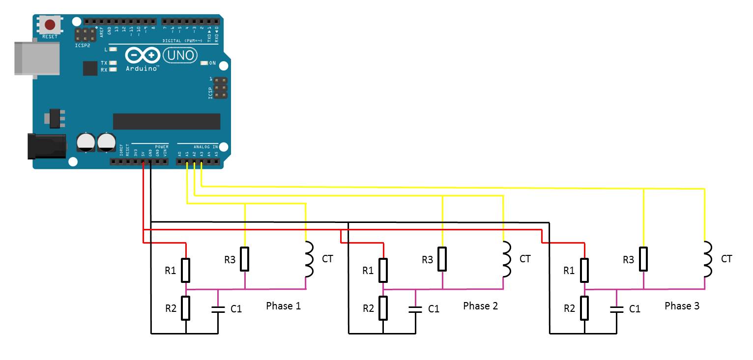
The basic circuit for the connection of the CTs to the Arduino is shown below:
Once you have connected all of your components, you need to connect your sensors onto the supply you want to monitor. For connection to a typical 3 phase mains supply, connect one CT around each of the phases as shown below.
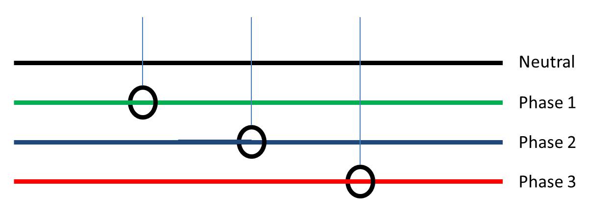
NB – Be careful when connecting the CTs to your mains and make sure that the power to your board is switched off before doing anything in the mains box. Do not remove any wires or remove any screws before checking your local regulations with your local authority, you may require a certified electrician to install the CT for you.
If you’d like to measure a larger or smaller amount of power more accurately, you’ll need to select different CTs. There is a detailed guide to selecting different CTs and their associated burden resistors in the original post.
Upload the Sketch
Now you can upload your sketch onto your Arduino, if you haven’t uploaded a sketch before then follow this guide on getting started.
//Michael Klements
//The DIY Life
//26 February 2017
//7 September 2017 Modified by Filip Ledoux
//V2.2
//Serial Display 20x4
//Ethernet

#include <Wire.h>
#include <LiquidCrystal_PCF8574.h>
#include <EEPROM.h>
#include <SPI.h>
#include <Ethernet.h>

LiquidCrystal_PCF8574 lcd(0x27);        // set the LCD address to 0x27 for a 16 chars and 2 line display

int show;

int currentPins[3] = {1,2,3};          //Assign phase CT inputs to analog pins
double calib[3] = {335.0,335.0,335.0};
double kilos[3];
unsigned long startMillis[3];
unsigned long endMillis[3];
double RMSCurrent[3];
int RMSPower[3];
int peakPower[3];

// Enter a MAC address and IP address for your controller below.
// The IP address will be dependent on your local network:
byte mac[] = { 0xDE, 0xAD, 0xBE, 0xEF, 0xFE, 0xEB };
IPAddress ip(192,168,1,12);
IPAddress gateway(192,168,1,1);
IPAddress subnet(255, 255, 255, 0);

// Initialize the Ethernet server library with the IP address and port you want to use (port 80 is default for HTTP):
EthernetServer server(80);

void setup()
{
  Serial.begin (9600);         // set the serial monitor tx and rx speed
  EEPROM.read (1);             // make the eeprom or atmega328 memory address 1

  // start the Ethernet connection and the server:
  Ethernet.begin(mac, ip, gateway, subnet);
  server.begin();
  Serial.print("server is at ");
  Serial.println(Ethernet.localIP());

  int error;

  lcd.begin(20, 4);          // initialize the lcd
  show = 0;

  lcd.clear();
  lcd.setBacklight(255);
  lcd.home();
  lcd.setCursor(0,0);         // set cursor to column 0, row 0
  lcd.print("3 Phase");
  lcd.setCursor(0,1);
  lcd.print("Energy Meter");
  lcd.setCursor(0,2);
  lcd.print("IP");
  lcd.setCursor(3,2);
  lcd.print(Ethernet.localIP());
  lcd.setCursor(0,3);
  lcd.print("V2.2");
  delay(2000);
}

void readPhase ()      //Method to read information from CTs
{
  for(int i=0;i<=2;i++)
  {
    int current = 0;
    int maxCurrent = 0;
    int minCurrent = 1000;
    for (int j=0 ; j<=200 ; j++)  //Monitors and logs the current input for 200 cycles to determine max and min current
    {
      current =  analogRead(currentPins[i]);  //Reads current input and records maximum and minimum current
      if(current >= maxCurrent)
        maxCurrent = current;
      else if(current <= minCurrent)
        minCurrent = current;
    }
    if (maxCurrent <= 517)
    {
      maxCurrent = 516;
    }
    RMSCurrent[i] = ((maxCurrent - 516)*0.707)/calib[i];    //Calculates RMS current based on maximum value and scales according to calibration
    RMSPower[i] = 235*RMSCurrent[i];    //Calculates RMS Power Assuming Voltage 220VAC, change to 110VAC accordingly
    if (RMSPower[i] > peakPower[i])
    {
      peakPower[i] = RMSPower[i];
    }
    endMillis[i]= millis();
    unsigned long time = (endMillis[i] - startMillis[i]);
    kilos[i] = kilos[i] + (RMSPower[i] * (time/60/60/1000000));    //Calculate kilowatt hours used
    startMillis[i]= millis();
  }
}

void loop() //Calls the methods to read values from CTs and changes display
{
  readPhase();
  displayKilowattHours ();
  delay(3000);
  readPhase();
  displayCurrent ();
  delay(3000);
  readPhase();
  displayRMSPower ();
  delay(3000);
  readPhase();
  displayPeakPower ();
  delay(3000);
}

void displayKilowattHours ()	//Displays all kilowatt hours data
{
  lcd.clear();
    lcd.setCursor(0,0);
    lcd.print("L1->");
  lcd.setCursor(5,0);
  lcd.print(kilos[0]);
  lcd.print("kWh");
    lcd.setCursor(0,1);
    lcd.print("L2->");
  lcd.setCursor(5,1);
  lcd.print(kilos[1]);
  lcd.print("kWh");
    lcd.setCursor(0,2);
    lcd.print("L3->");
  lcd.setCursor(5,2);
  lcd.print(kilos[2]);
  lcd.print("kWh");
  lcd.setCursor(5,3);
  lcd.print("Energy");
}

void displayCurrent ()	//Displays all current data
{
  lcd.clear();
    lcd.setCursor(0,0);
    lcd.print("L1->");
  lcd.setCursor(5,0);
  lcd.print(RMSCurrent[0]);
  lcd.print("A");
    lcd.setCursor(0,1);
    lcd.print("L2->");
  lcd.setCursor(5,1);
  lcd.print(RMSCurrent[1]);
  lcd.print("A");
    lcd.setCursor(0,2);
    lcd.print("L3->");
  lcd.setCursor(5,2);
  lcd.print(RMSCurrent[2]);
  lcd.print("A");
  lcd.setCursor(5,3);
  lcd.print("Current");
}

void displayRMSPower ()	//Displays all RMS power data
{
  lcd.clear();
    lcd.setCursor(0,0);
    lcd.print("L1->");
  lcd.setCursor(5,0);
  lcd.print(RMSPower[0]);
  lcd.print("W");
    lcd.setCursor(0,1);
    lcd.print("L2->");
  lcd.setCursor(5,1);
  lcd.print(RMSPower[1]);
  lcd.print("W");
     lcd.setCursor(0,2);
    lcd.print("L3->");
  lcd.setCursor(5,2);
  lcd.print(RMSPower[2]);
  lcd.print("W");
  lcd.setCursor(5,3);
  lcd.print("Power");
}

void displayPeakPower ()   //Displays all peak power data
{
  lcd.clear();
    lcd.setCursor(0,0);
    lcd.print("L1->");
  lcd.setCursor(5,0);
  lcd.print(peakPower[0]);
  lcd.print("W");
    lcd.setCursor(0,1);
    lcd.print("L2->");
  lcd.setCursor(5,1);
  lcd.print(peakPower[1]);
  lcd.print("W");
    lcd.setCursor(0,2);
    lcd.print("L3->");
  lcd.setCursor(5,2);
  lcd.print(peakPower[2]);
  lcd.print("W");
  lcd.setCursor(5,3);
  lcd.print("Max Power");

 // listen for incoming clients
EthernetClient client = server.available();
  if (client) {
    Serial.println("new client");
    // an http request ends with a blank line
    boolean currentLineIsBlank = true;
    while (client.connected()) {
      if (client.available()) {
        char c = client.read();

     Serial.write(c);
        // if you've gotten to the end of the line (received a newline
        // character) and the line is blank, the http request has ended,
        // so you can send a reply
        if (c == '\n' && currentLineIsBlank) {


          // send a standard http response header
          client.println("HTTP/1.1 200 OK");
          client.println("Content-Type: text/html");
          client.println();
          client.println("<HTML>");
          client.println("<HEAD>");
          client.print("<meta http-equiv=\"refresh\" content=\"2\">");//refresh page every 2 sec
          client.print("<TITLE />Zoomkat's meta-refresh test</title>");
          client.println();
          client.println("<!DOCTYPE HTML>");
          client.println("<html>");
          //client.println("<FONT SIZE=12>");
          client.println("<BODY TEXT=black BGCOLOR=white>");
          client.println("<b>""Energy Display""</b>");
          client.println("<hr />");


          client.println("<mark>""RMS current:""</mark>");
          client.println("<p>");
          client.println("<b>""L1:""</b>");
          client.println( RMSCurrent[0]);
          client.println("<p>");
          client.println("<b>""L2:""</b>");
          client.println( RMSCurrent[1]);
          client.println("<p>");
          client.println("<b>""L3:""</b>");
          client.println( RMSCurrent[2]);
          client.println("<hr />");

          client.println("<mark>""KWH:""</mark>");
            client.println("<p>");
          client.println("<b>""L1:""</b>");
          client.println( kilos[0]);
          client.println("<p>");
          client.println("<b>""L2:""</b>");
          client.println( kilos[1]);
            client.println("<p>");
          client.println("<b>""L3:""</b>");
          client.println( kilos[2]);
          client.println("<hr />");

          client.println("<mark>""RMS power:""</mark>");
            client.println("<p>");
           client.println("<b>""L1:""</b>");
          client.println( RMSPower[0]);
          client.println("<p>");
          client.println("<b>""L2:""</b>");
          client.println( RMSPower[1]);
            client.println("<p>");
          client.println("<b>""L3:""</b>");
          client.println( RMSPower[2]);
          client.println("<hr />");

          client.println("<mark>""MAX power:""</mark>");
            client.println("<p>");
           client.println("<b>""L1:""</b>");
          client.println( peakPower[0]);
          client.println("<p>");
          client.println("<b>""L2:""</b>");
          client.println( peakPower[1]);
            client.println("<p>");
          client.println("<b>""L3:""</b>");
          client.println( peakPower[2]);
          client.println("<hr />");


   // give the web browser time to receive the data
   delay(100);
// close the connection:
   client.stop();
Serial.println("client disconnected");

      }
    }
  }
    }
}
Here is the link to download the code – EnergyMonitorEthernet
In order to get the Ethernet portion working for your meter, you’ll need to put in the mac address and IP address for your controller in lines 30-33. The mac address can in some cases be made up and in other cases will be printed on a sticker on the board, it depends on the manufacturer of your Ethernet shield. The IP addresses and port will depend on your local network. If you are unfamiliar with using an Ethernet shield with an Arduino board, have a look at this guide on how to set up an Ethernet connection on an Arduino.
Because your setup, CTs , resistors and input voltages may be different, there are scaling factors in the sketch which will need to be adjusted until you get the correct results. These values are stored in an array in line 20 – double calib[3] = {335.0,335.0,335.0}. If everything is connected correctly, at this point you should at least get some figures displayed on the screen although they will most likely be incorrect and some may be negative.
Calibrate the Current Reading
As mentioned above, because your setup, CTs , resistors and input voltages may be different, there is a scaling factor in the sketch for each CT which you will need to change before you will get accurate results.
To calibrate your energy meter, you need to be sure that the current that your meter says is being drawn on each phase is what you expect is actually being drawn. In order to do this accurately, you need to find a calibrated load. These are not easy to come by in a normal household so you will need to find something which uses an established and consistent amount of power. I used a couple of incandescent light bulbs and spot lights, these come in a range of sizes and their consumption is fairly close to what is stated on the label, ie a 100W light bulb uses very close to 100W of real power as it is almost entirely a purely resistive load.
Plug in a small light bulb (100W or so) on each phase and see what load is displayed. You will now need to adjust the scaling factors defined in line 20 accordingly:
double calib[3] = {335.0,335.0,335.0}
In this case 335.0 for phase 1, 335.0 for phase 2 and 335.0 for phase 3 have been used as a starting point. They may be higher or lower depending on your application. Either use linear scaling to calculate this figure or, if you’re not good with math, play around with different values until the load you have plugged in is shown on the energy meter’s screen.
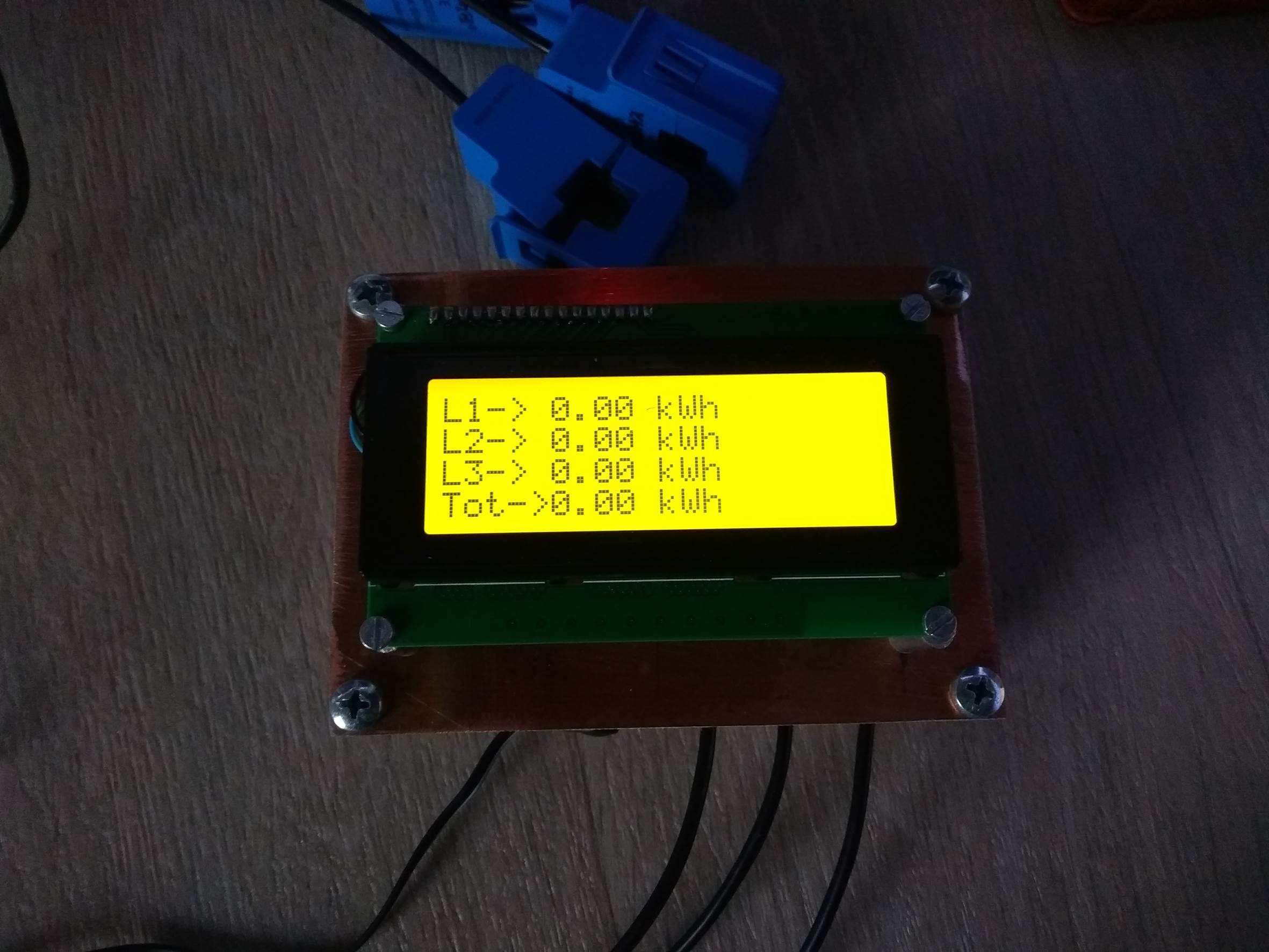
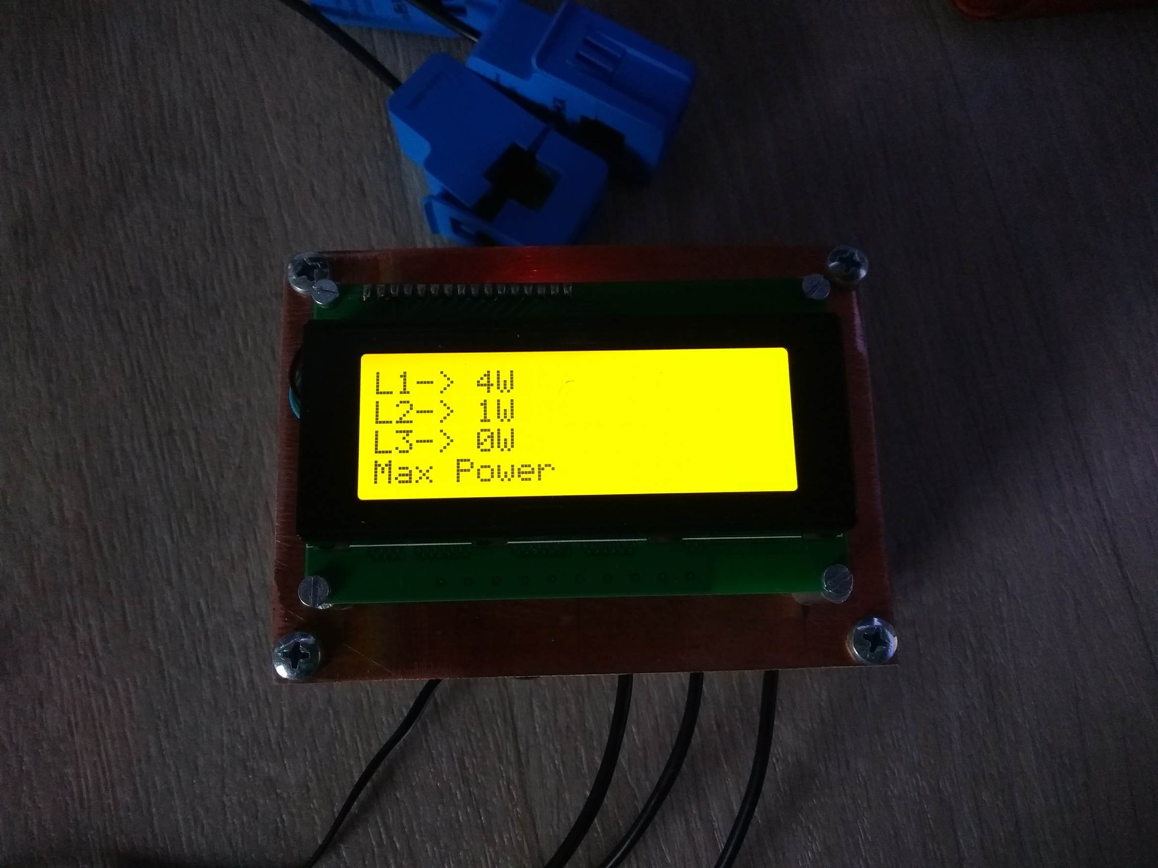
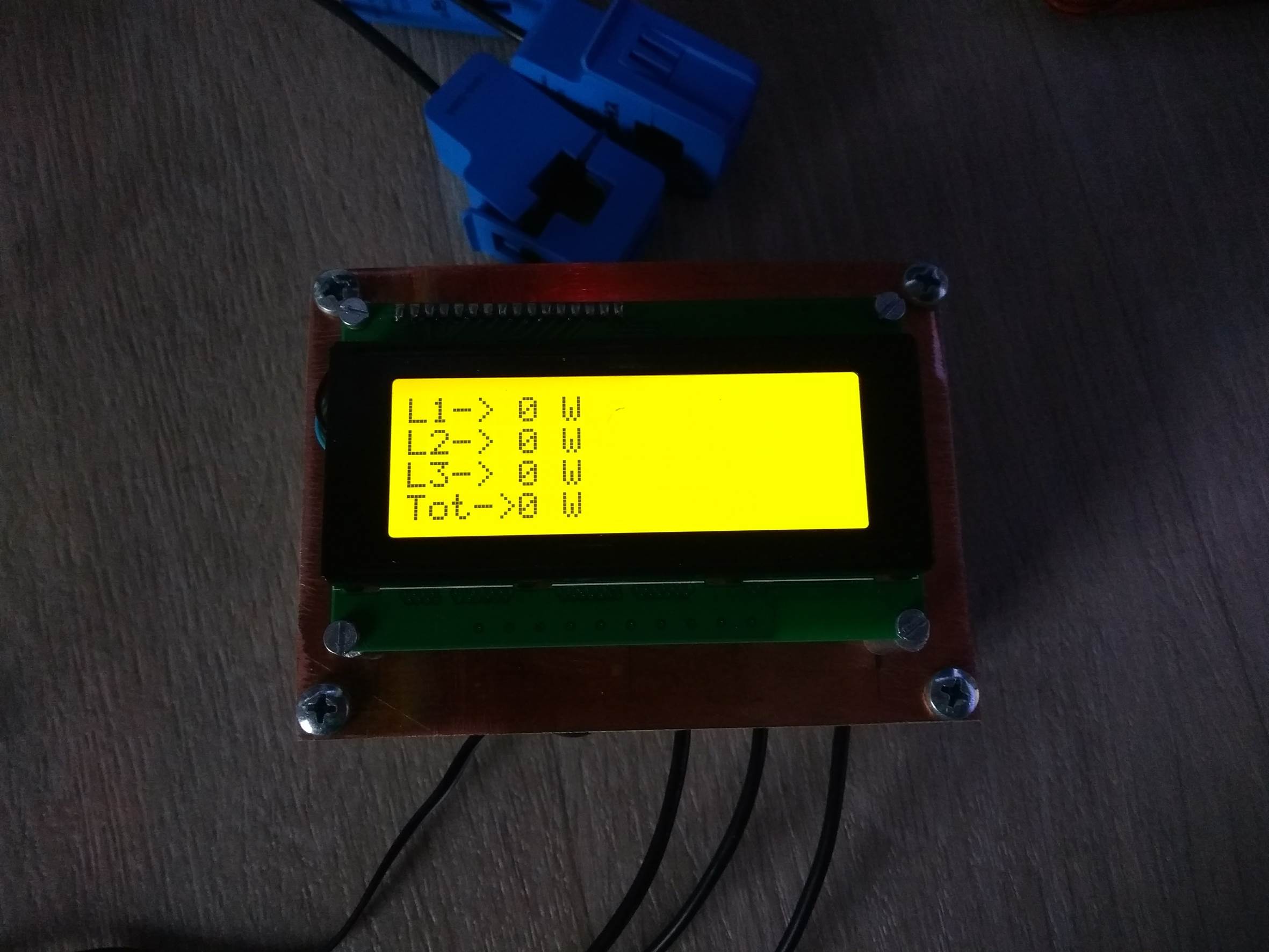
The Energy Meter In Operation
Once you have your energy meter calibrated and the scaling factors have been uploaded onto the Ardunio, your meter should be ready to connect and leave to monitor your energy consumption. Here are some photos of Filips completed energy meter in operation.
How did this project go for you? What have you used it to monitor? If you have any questions or would like to share your build of this three phase energy meter, please post a comment below or send a mail using the contact form.
I test it with by giving MY Server IP address & MAC address, but I did not get any data in My server, Server not get connected but in serial monitor showing staring W5100
192.168.1.62
I am very happy any body help me, all connections & LAN every thing is correct, My server is Tomcat-7, My SQL
Hi Virupakshacharya,
Try building your way up to what you are trying to achieve in smaller steps. It is quite difficult to troubleshoot your setup when you’re trying something quite complex right off the start. To start off, try connecting your Arduino through a crossover cable or simple switch to your computer and get the basic communications working. Once you have this working then you can move on to using your server.
Hi
Can Arduino handle AC? I was working on a kind of same project but was first trying tot transfer to DC.
Hi Rene,
Your question is a bit vague. No you can’t just connect your home’s AC mains to an Arduino but you can scale down the voltage and input it if you write the correct software to read it.
Hey, I couldnt post a coment on 1 phase energy meter so here it is:
I tried to recreate it using your components. But it gives me 1023 number despite there is only 2,7V on input. When there is no AC current it gives good 512 (or something simmilar) number. It can detect something less than 60W if 60W will be calibrated as maximum.
What can be the problem?
Kind Regards
Peter
Hi Peter,
What CT are you using and with what size burden resistor at what supply voltage. It sounds like these are incorrectly sized so even a small flow of current is applying the full 5V to the Arduino input.
Hi!
Great post!
How about to add temperature readings, for about 3 temperatures.
So, add one more 4×20 screen, probes
Can one arduino board with web board show all data on the net?
Coding ?
Hi Michael
have built 3-phase energy meters with Ethernet connection unfortunately I get wrong values displayed.
I have entered all values in line 20 up and down no result
My hairdryer has 1500W and 6.5A displays are 11A and 350W.
The SCT-013 has 30A / 1V from the company http://WWW.yhdc.com we have a network in Germany of 230V.
I need the system to get out the individual phases in my house because I would like to connect an emergency power agregat in case of emergency.
Can unfortunately no English must work with translator
you can help
Greetings from DRESDEN/SACHSEN
Rolf Krueger
Translated with http://www.DeepL.com/Translator
Good day!!. I would like someone to help me to enter the correct sentences so as not to lose the data if there is a power outage using the EEPROM.h library. Thanks a lot!!!
Hi Cristian,
I haven’t really used the EEPROM.h library for storing data but I have had a few people ask about using it recently. I’ll look into it and see if it can be used to provide a backup when the energy meter loses power.
Thank you very much michael for the answer. I’ve really tried but since I’m not an expert, I can’t make it work.
I have tested with EEPROM functions. UPDATE, EEPROM. PUT and EEPROM.GET, but having no experience I can’t make it work for me. What I do know is that a sampling should be done every 4 hours approx. It will preserve the state of eeprom memory since it is limited.
Again I appreciate your help.
Regards Cristian. From Argentina
Hai,,, can you show how to print voltage 380v in this projects, because i see this only power consumtion.
I need formula for calculate a measurnent 3 phase voltage (380-400 v)?
Trims
Hi Firdos,
You can’t calculate the voltage using this meter as you’re only measuring the current through each phase. To be able to display the voltage, you’d need to connect a voltage sensor or transformer which steps your 380-400V down to a 5V input to be read on your analogue inputs.