In this project, we’re going to be making a set of wirelessly controlled animatronic eyes. I’ve been wanting to do this project for a while, so when Quantum Integration launched their new Motor & Servo Driver board, this project immediately came to mind. Their new board is based on the PCA9685 driver chip, so you can also build a similar setup using an ESP32 or Arduino if you’d like.
Here’s my video of the build, read on for the write-up:
What You Need For This Project
- Quantum Integration Starter Bundle – Buy Here
- Quantum Integration Motor & Servo Driver Board – Buy Here
- 6 Micro Servos – Buy Here
- 2 Universal Joints – Buy Here
- M2 Screws & Nuts – Buy Here
- Cotton Thread – Buy Here
- Breadboard Jumpers – Buy Here
Equipment Used
- Creality Ender 3 V2 3D Printer – Buy Here
- Electric Screwdriver Set – Buy Here
- Glue Gun – Buy Here
- TS100 Soldering Iron – Buy Here
Some of the above parts are affiliate links. By purchasing products through the above links, you’ll be supporting this channel, with no additional cost to you.
Designing & Printing The Animatronic Eye Components
I started out by drawing up a 3D model in Fusion 360. I knew roughly what I wanted the final set of eyes to look like, but naturally had to make a few tweaks along the way.
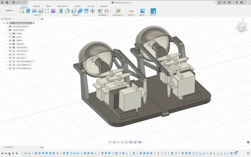
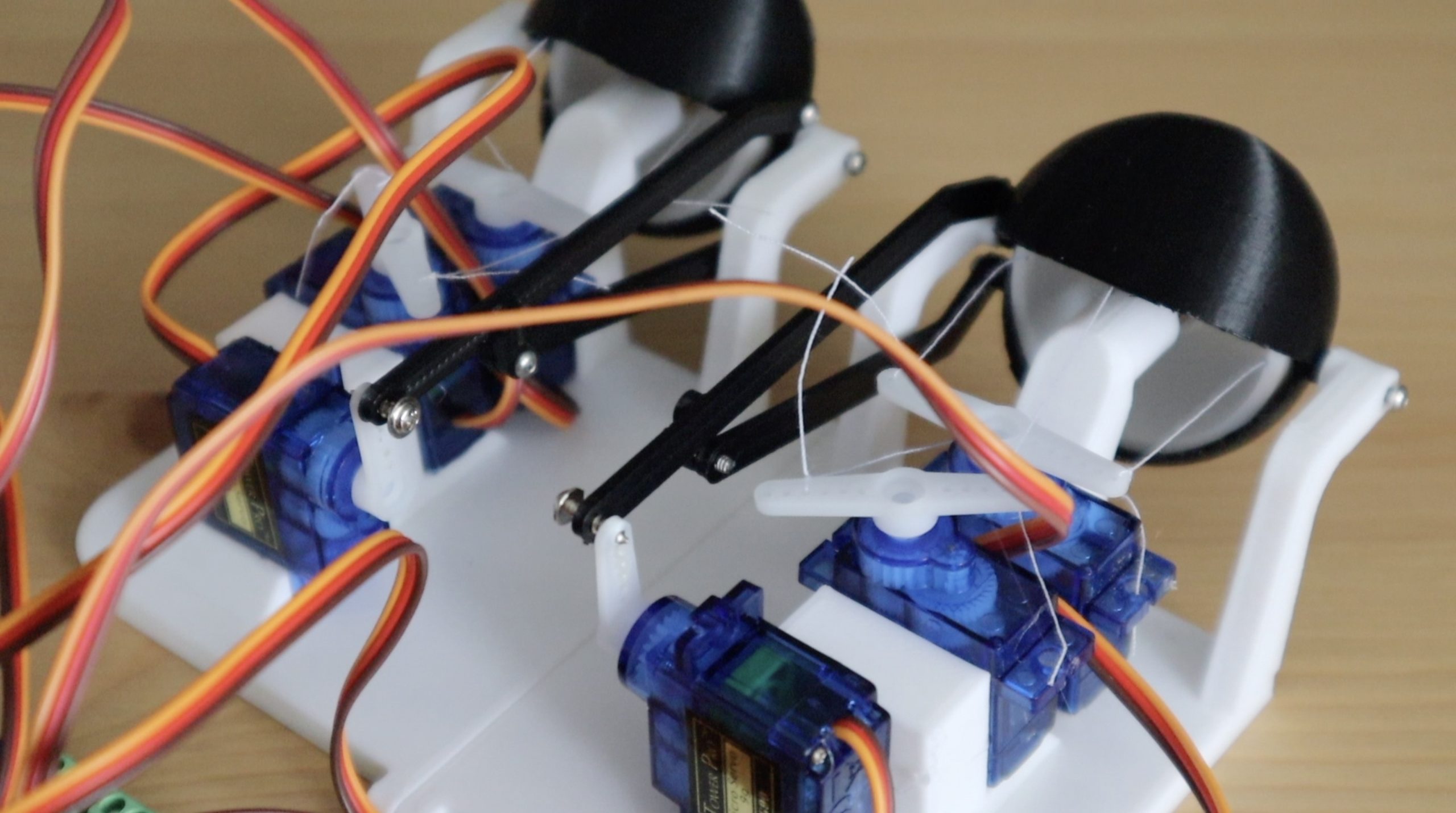
I wanted the eyes to be able to move left and right as well as up and down, so I needed two servos for each of them. I also wanted to have eyelids that could blink, and in future maybe wink independently, so I needed another two servos for those movements as well. At the centre of each eyeball is a small brass universal joint and I’m going to use some cotton thread to connect each eyeball to the servos rather than using solid pushrods.
I had to go through a couple of trial prints to see what tolerances and clearances worked well. My first set of eyeballs was too big and got caught on the eyelids, but making them too small also left large weird looking gaps between the eyes and the eyelids, so that was also no good.
I also had to split the base to allow the screws that hold the eyelids to be installed so close together.
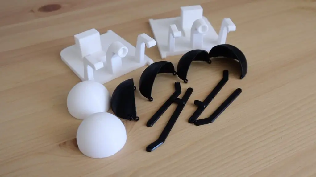
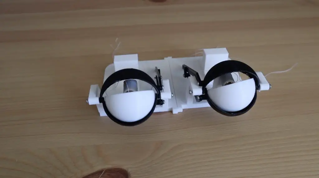
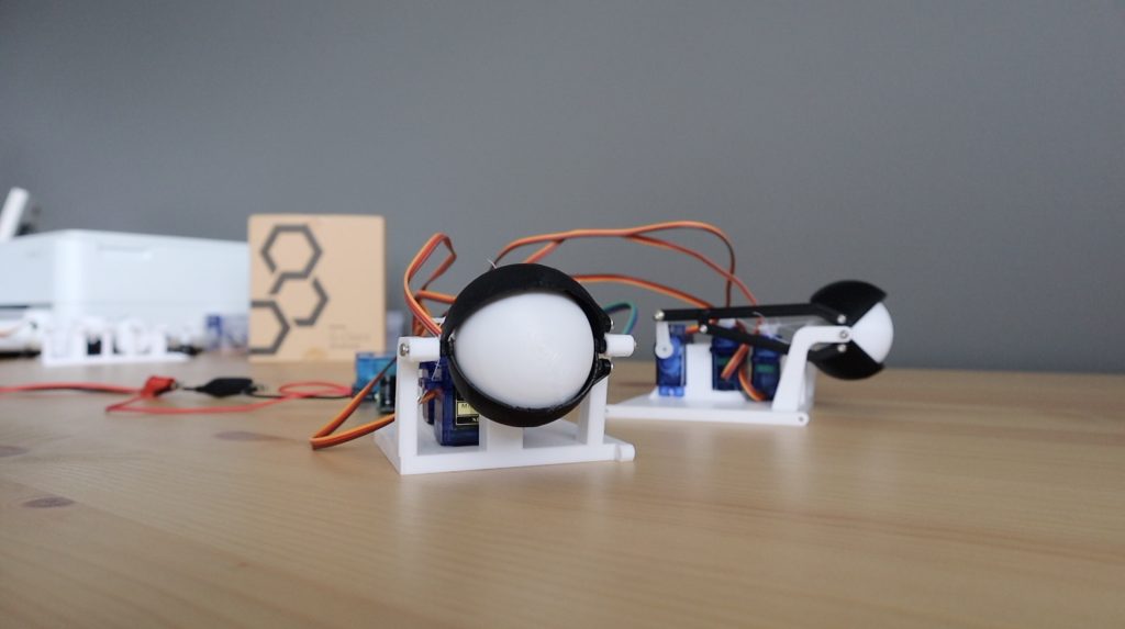
But eventually, I had a set of 3D prints that could be assembled into a working set of eyes.
If you’d like to 3D print your own eyes, the 3D model files for my projects are now available to my Patrons on Patreon or on my Etsy store.
Assembling The Eye Components
To assemble the eyes, we just need two small universal joints for 3mm shafts and some M2 screws and nuts.
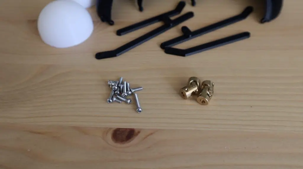
These are the ones that were locally available for me. I’ve linked very similar ones in the parts list, but you might need to make some minor adjustments to fit the ones that are available to you. You’ll also some cotton thread or thin string to connect the eyeballs to the servos.
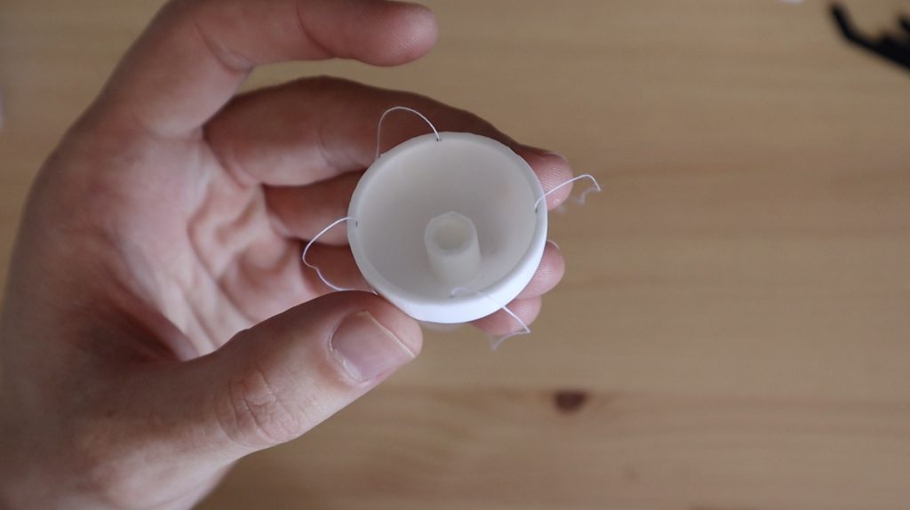
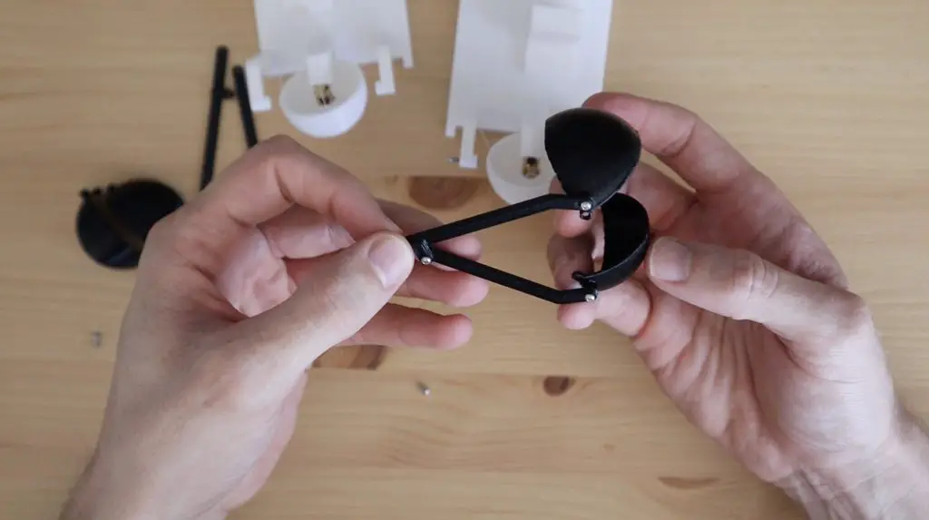
Let’s start by adding the thread to the eyeballs. We just need to glue a 10cm length of thread to four opposing inside edges of each eyeball. The eyeballs are round and don’t have any holes in them, so it doesn’t matter which four locations you choose, as long as they are equally spaced. I used a drop of superglue on the end of each length of thread.
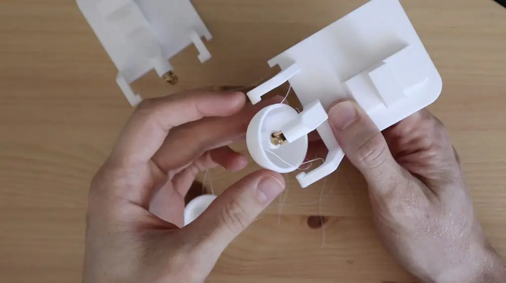
We can then press the universal joints into the 3D printed bases. Mine are a tight fit, but if yours are a bit loose you can secure them with a little bit of glue as well. Just make sure that you don’t get glue in the universal joint’s pins or it’ll lock up.
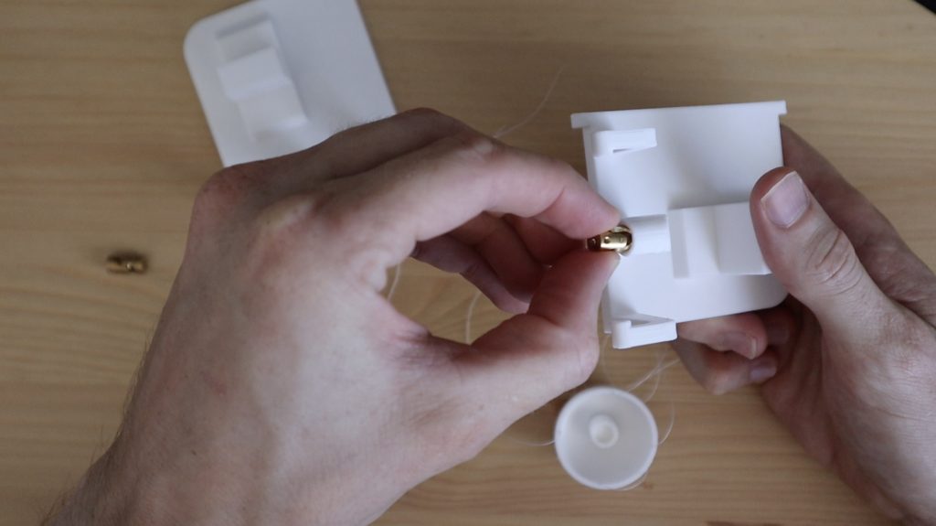
Then we can push each of the eyeballs onto the universal joints as well.
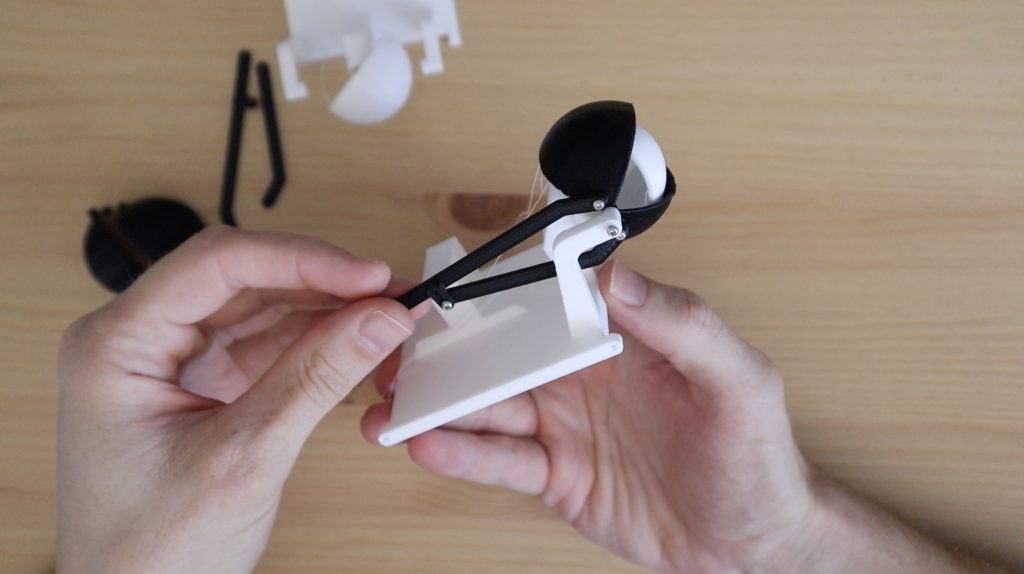
Now let’s add our eyelids. These pivot around some M2 screws in the holder on either side of each eye. Prepare the base by screwing these M2 screws into each side, with just one or two turns of thread exposed on the inside.
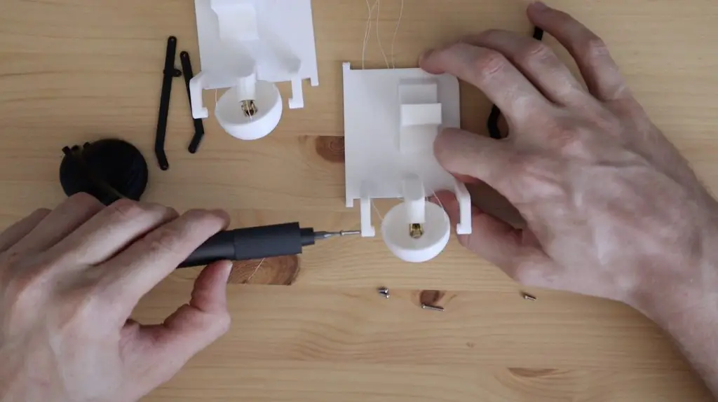
A 3D printed pushrod is then going to be connected between each eyelid and the servo behind it to open and close it. The top pushrod is the longer one with a small extension on it to connect to the bottom pushrod.
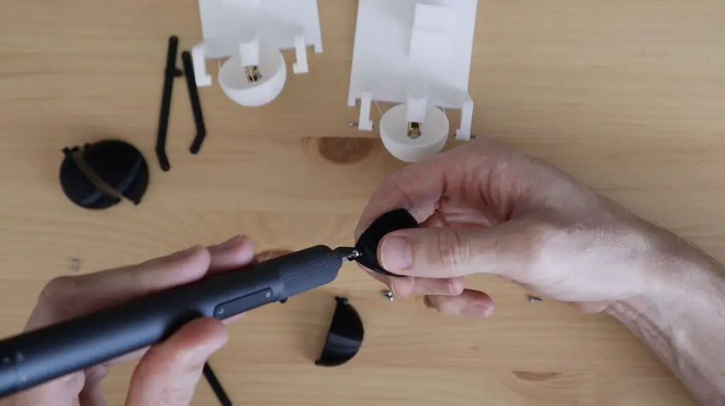
The screws need to be adjusted a bit, you want them tight enough that they hold the components in place, but still allow free movement. You might need to iteratively tighten or loosen them to get them right.
Place the set of eyelids between the screws on the base and slowly tighten them until the eyelids are held in place. Make sure that the screws don’t protrude too far on the inside of the eyelids and touch the eyeballs.
The pushrod should be free and easy to gently push and pull to open and close the eyelids.
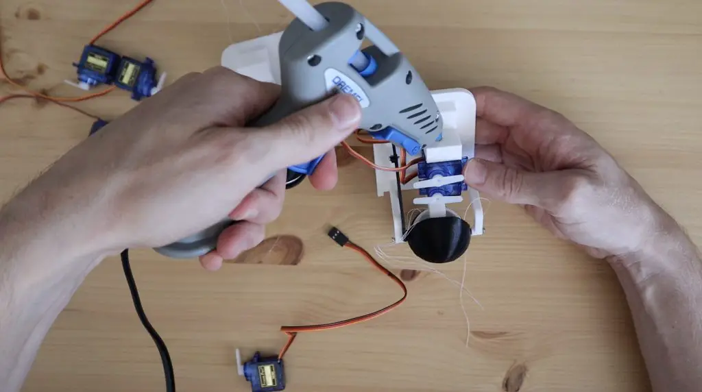
Once we have our eyes and eyelids assembled, we can add our servos. I’m using 6 micro servos, three for each eye.
These are just glued into place on their supporting faces as they’re shown in the model. Install the servos on both base assemblies with the second eye being a mirror image of the first.
Lastly, tie the cotton thread to your two front servos. This was quite a fiddly job – make sure that you tie them off so that there is a bit of tension on the eye to stop it from wobbling. Also, don’t screw the white control arms onto the servos yet as you might need to adjust them once the servos are powered and centred.
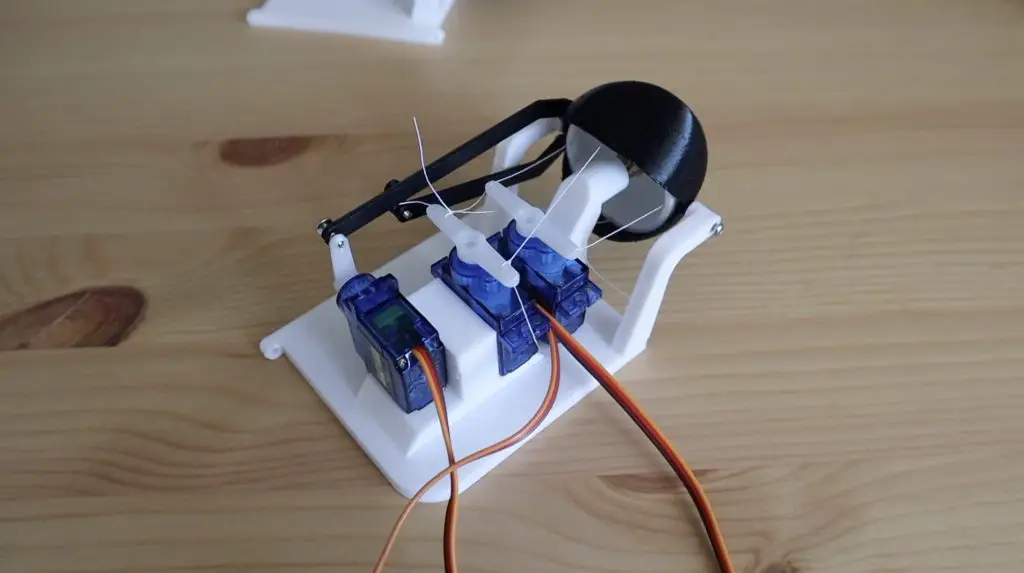
With that done, the eyes are now complete and are ready to add the electronics to.
Connecting The Electronics
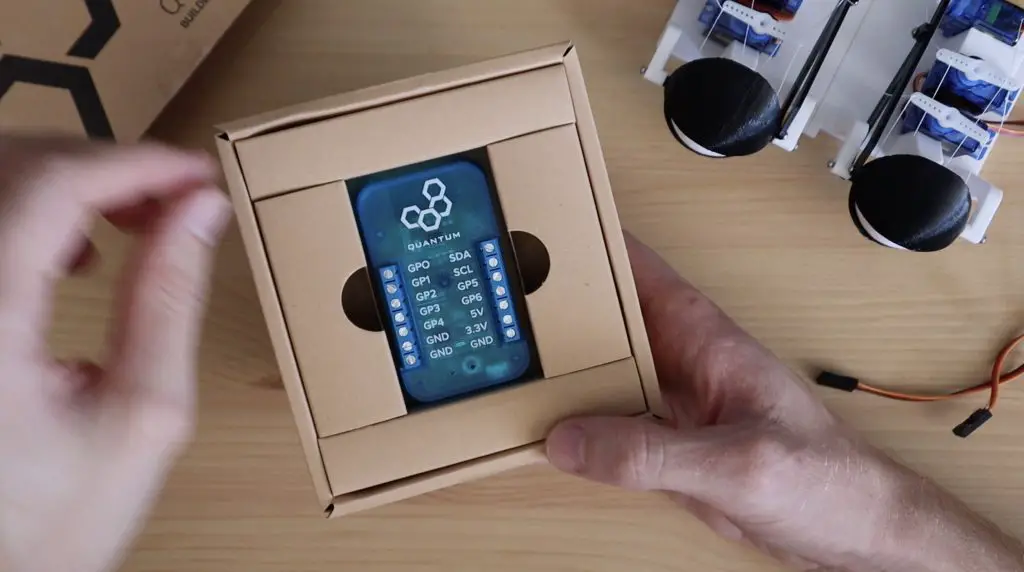
As I’m using the Quantum Integration system, I need a build base to wirelessly control the eyes and I’m going to use one of their four new DIY kits, the Motor and Servo Driver to drive the servos.
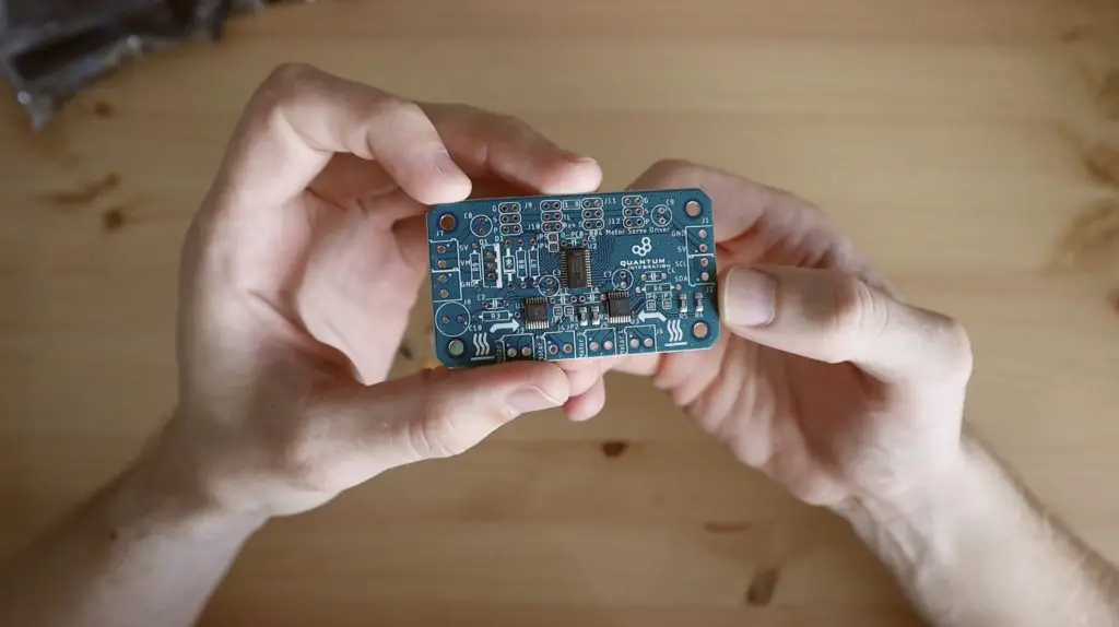
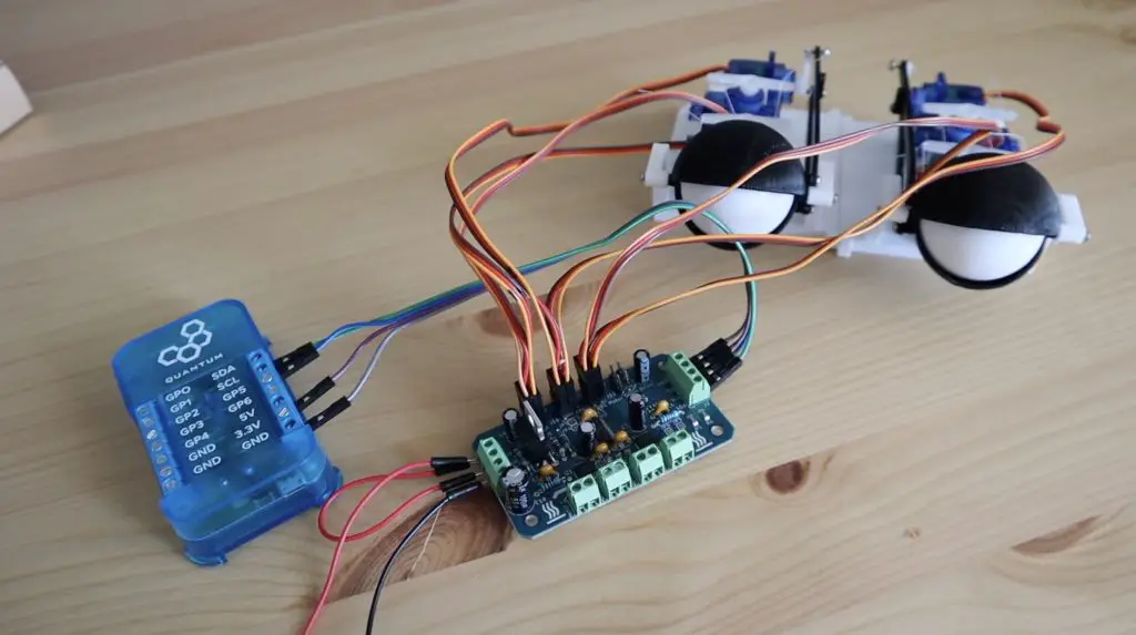
The Motor & Servo driver board allows you to control up to 8 servos and 4 motors with the I2C interface on your builder base, so it’s perfect for the 6 servos used in our project. The boards come as a kit with all of the surface-mounted components pre-soldered, you just need to add the through-hole ones.
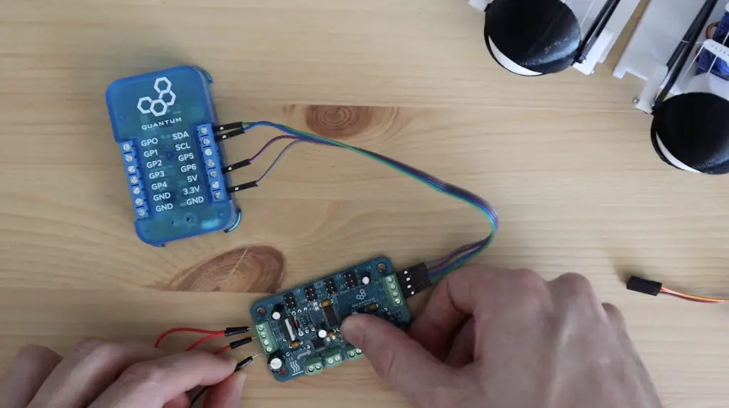
Once the board is assembled, we can pair up the driver and builder base and plug in our servos. As I mentioned earlier, the driver uses the I2C interface, so we just need to make connections between the 5V, GND, SCL and SDA pins on each. The builder base is going to get its power through the servo driver board, so we only need to supply power to the driver board, which we do through the 5V and GND pins on the left of the board.
Note: You don’t actually need the jumper between 5V and VM that I’ve used as the servos are powered through the 5V supply. VM only supplies power for the DC motor outputs.
Then just plug the servos into the driver board and we can then move on to programming it. I’ve connected the servos on outputs 1-6 as below:
- 1 – Left Eye – Left Right
- 2 – Left Eye – Up Down
- 3 – Left Eye – Blink
- 4 – Right Eye – Left Right
- 5 – Right Eye – Up Down
- 6 – Right Eye – Blink
Creating The App and Firmware
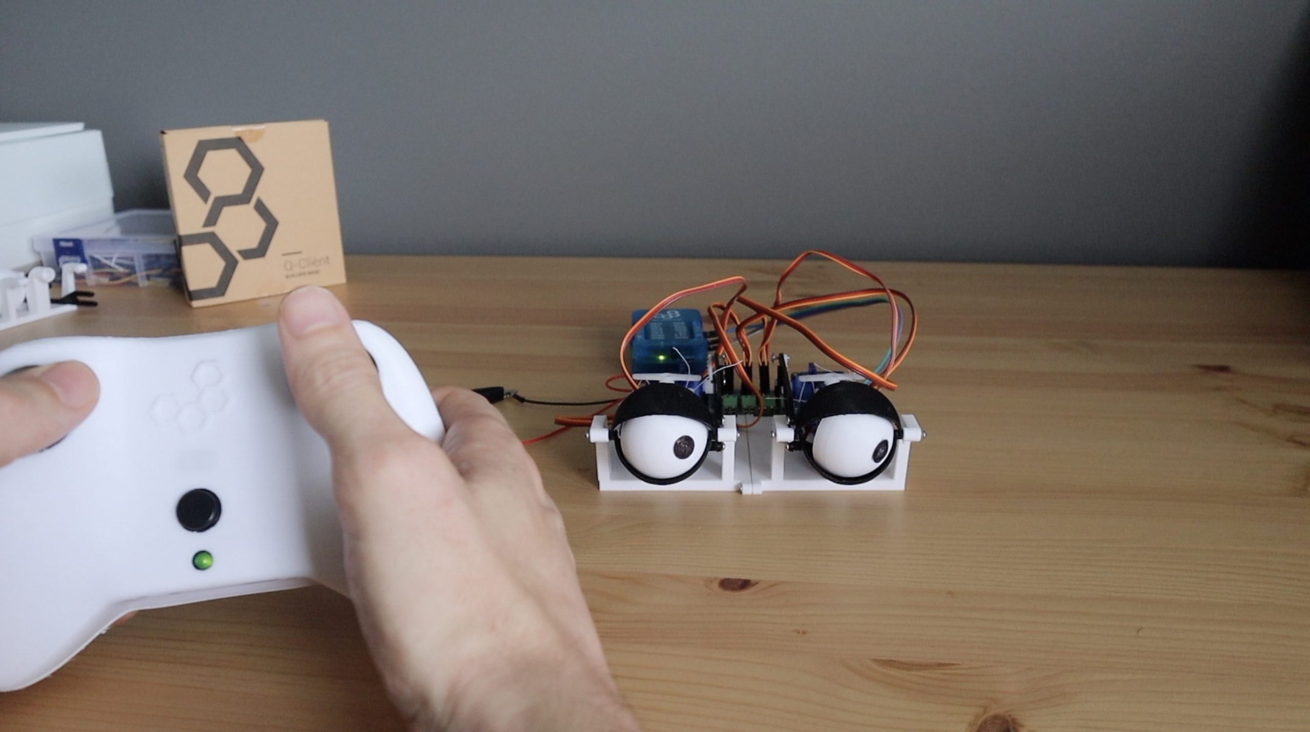
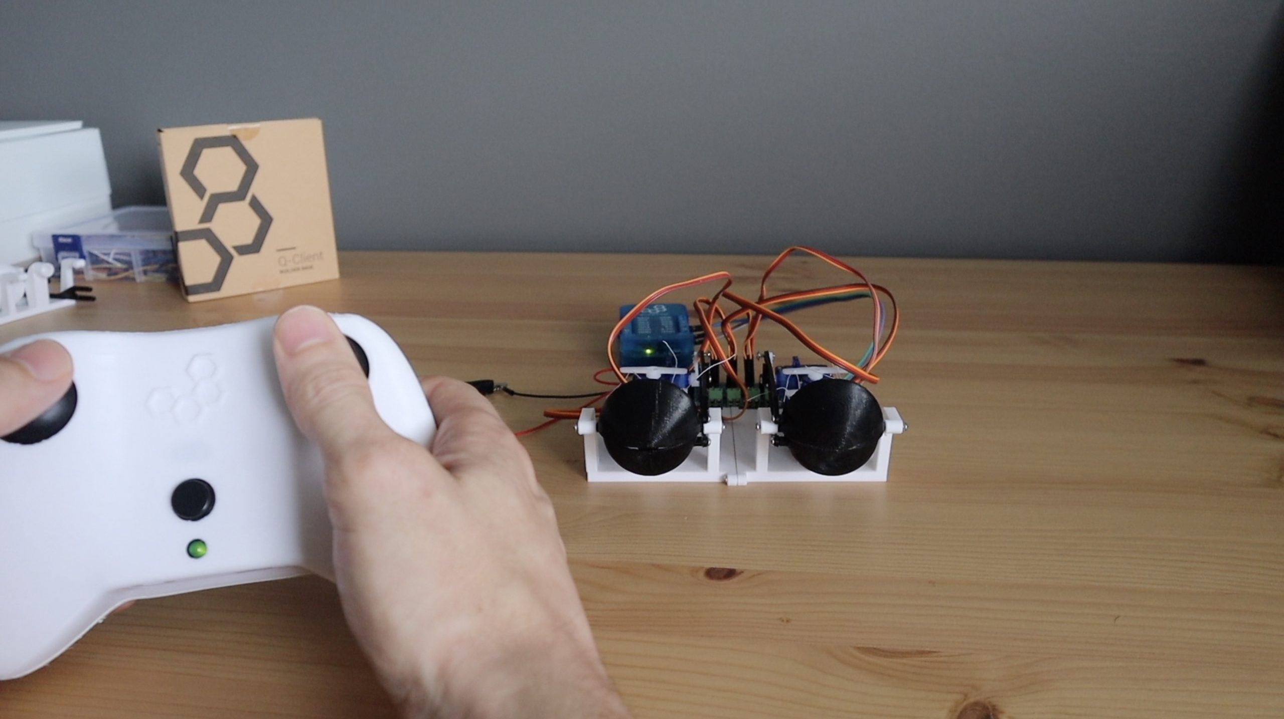
Now let’s log into our Q-Server and have a look at the App to control the eyes.

We’d got two joystick inputs on the left, one for the left stick and one for the right stick. The x and y axis on the left stick will control the eye movement and the button on the right stick will control the blinking.
These then feed into the three controls on our web dashboard, so that we can control the eyes from the web interface as well. We have two analogue sliders, one for the left and right movement and one for the up and down movement, and then a button to blink.
The web controls then feed into some ranging blocks which set directions and travel limits for the servos and then finally feed into each of the six servos on the right. So we have the left and right movement servos at the top, the up and down movement servos in the middle and the blinking servos at the bottom.
Lastly, before we run the app, we need to create our builder base firmware to tell the builder base which servo is connected to which driver output. These are identified by a channel number for each servo object as follows:
- Servo 1 – Channel 3
- Servo 2 – Channel 2
- Servo 3 – Channel 1
- Servo 4 – Channel 0
- Servo 5 – Channel 15
- Servo 6 – Channel 14
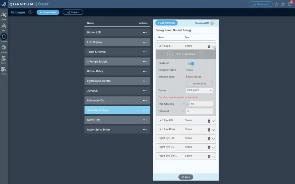
I started out by only enabling a single eye to test the App and firmware. It looked like the eye movement was set up nicely and the blinking worked well too.
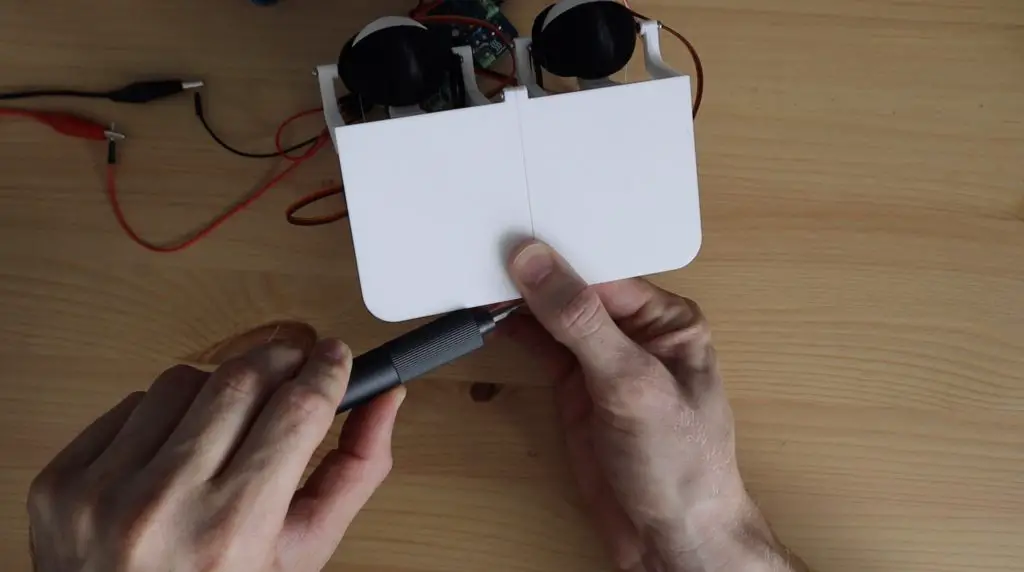
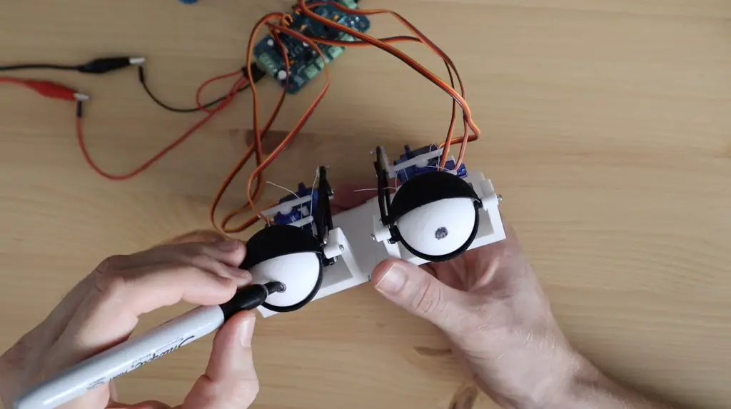
We can now finish off the build by screwing the two bases together and marking the eyeballs with a pupil using a black Sharpie. If you’ve printed the eyeballs with the back surface on the print bed then the concentric circles of each layer can be used as a guide for marking the pupils.
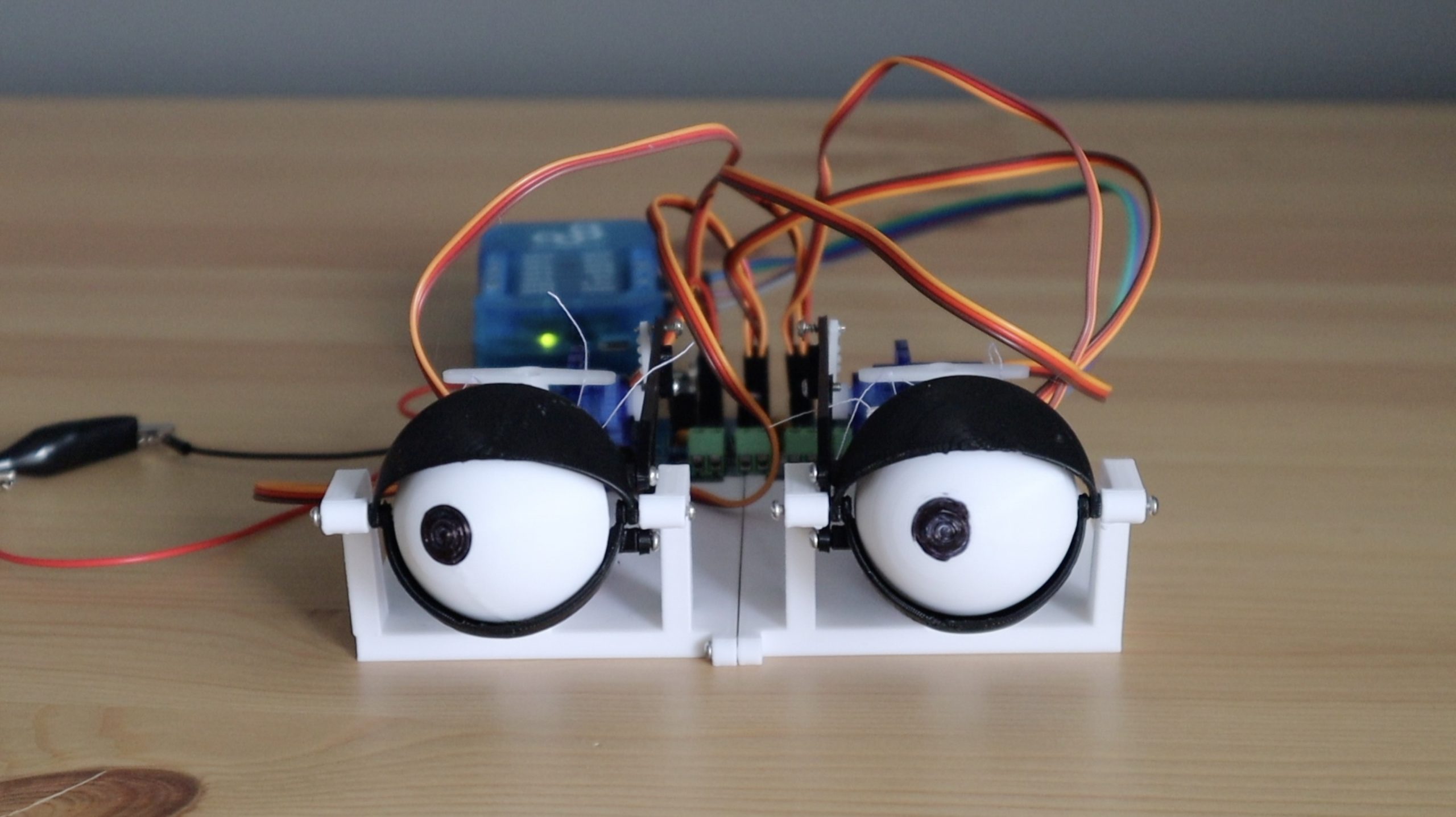
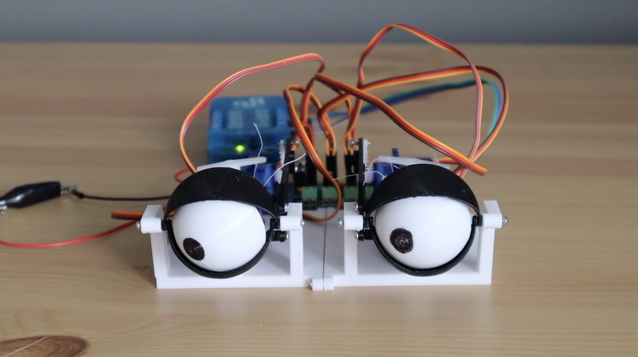
The Completed Eyes & Final Thoughts
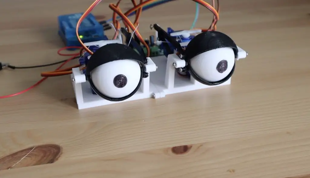
Overall I’m quite impressed with how well these animatronic eyes turned out. The blinking works better than I expected it, and the cotton thread to the eyes holds up really well as a cheaper alternative to solid pushrods. I definitely think that solid pushrods are a more robust solution, but these work perfectly for a short term solution.
Let me know what you think of them in the comments section below.
Hello Michael
Your project is very creative
I want to ask a question
What is the smallest diameter of the eye with the eyelid that can be used in your project
Is it possible to make?
I want to buy your project, but the eye with the eyelid must have a diameter of 12 mm or a little more
I want to buy 12 pairs of your project
Eagerly waiting for your reply
Is there a contact phone number or Facebook page?
Thank you so much
Email : diaa05@hotmail.com
Hi Diaa,
You probably won’t be able to get them much smaller than what they currently are. As they’re 3D printed, you’re limited by the resolution and print quality of the printer. If you make them any smaller then you start getting interferences between parts etc..
hello dear
hope you doing well, I’m really interesting for your project!
could you pls share the stl file for the 3d printer regarding this topic with me?
thank you.
my name is,
Rawan Moftah from KSA
innovation Manager
00966500038628
thanks
Hello! I’m looking through the list of hardware needed for this project, and it seems that Quantum Integration doesn’t sell any of their kits and parts any more. What alternatives or substitutions do you suggest to still have this work?
Hello!
I have just bought your pack. The Quantum Integration dont sell any of their kits and parts any more. What alternatives or substitutions would you suggest ?
Thank you