A while ago I did a bit of an experiment to compare the sound level between TMC2208 and A4988 stepper motor drivers. At the time, A4988 drivers were more commonly used on 3D printers and other hobby CNC devices. Since then, most 3D printer and CNC laser manufacturers have moved towards replacing at least the X and Y axis motors with the silent TMC2208 stepper motor driver or some other variant of silent motor driver. A question that has come up quite a lot in the video’s comments was how these drivers manage to drive the motors with such a significant sound reduction and if there was any trade-off.
So rather than just show you some diagrams, I thought I’d set the motor and drivers up again and try to show you through actual measurements.
Here’s my video of the test – read on for the write-up, although the video is the best way to hear the sound difference for yourself.
What You Need To Set Your Own Test Up
To set up your own test like I’ve done, you’ll need a few basic components:
- TMC2208 Stepper Motor Driver – Buy Here
- A4988 Stepper Motor Driver – Buy Here
- Arduino Uno – Buy Here
- Nema 17 Stepper Motor – Buy Here
- Basic Breadboad Kit – Buy Here
- 12V DC Power Supply – Buy Here
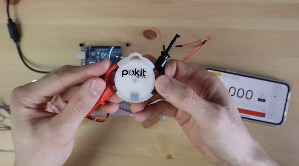
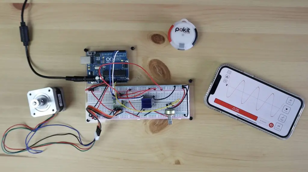
I’m going to be using a Pokit multimeter to take current measurements using the oscilloscope function. You don’t need one of these if you just want to hear the sound difference or tinker with controlling the motors.
Understanding How Stepper Motors Work
There are some really good resources online to explain how stepper motors work, so I’m not going to go into too much detail. The simple explanation is that stepper motors have a number of poles and the driver energises the coils in the motor to align the rotor with these poles in a sequence to rotate it.
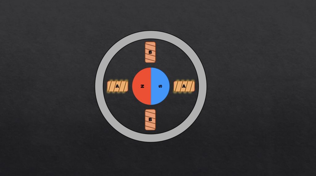
The simplest way to do this is to turn one pole on and the other off, causing the rotor to jump from one pole to another. This is simple to do electrically but causes the most noise as it induces a lot of vibration within the motor.
We can reduce the noise by rather slowly energising the one coil while de-energising the second coil so that we gently pass the rotor from one step to the next. The most optimal way to do this without producing any vibration is by producing a sinusoidal wave.
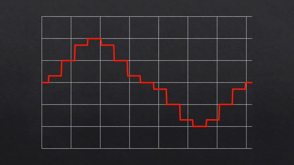
The better the stepper motor driver can replicate a sinusoidal waveform, the quieter it’s going to be able to run the motor. But replicating a sine wave perfectly requires more expensive electronics, so there is a bit of a tradeoff.
There are a few other sources of noise or humming in a stepper motor caused by things like magnetic fields, current ripple and chopper frequency. But their contribution is generally significantly less than this is.
So let’s have a look at the current waveform that the two drivers produce.
The TMC2208 Driver Test Setup and Code
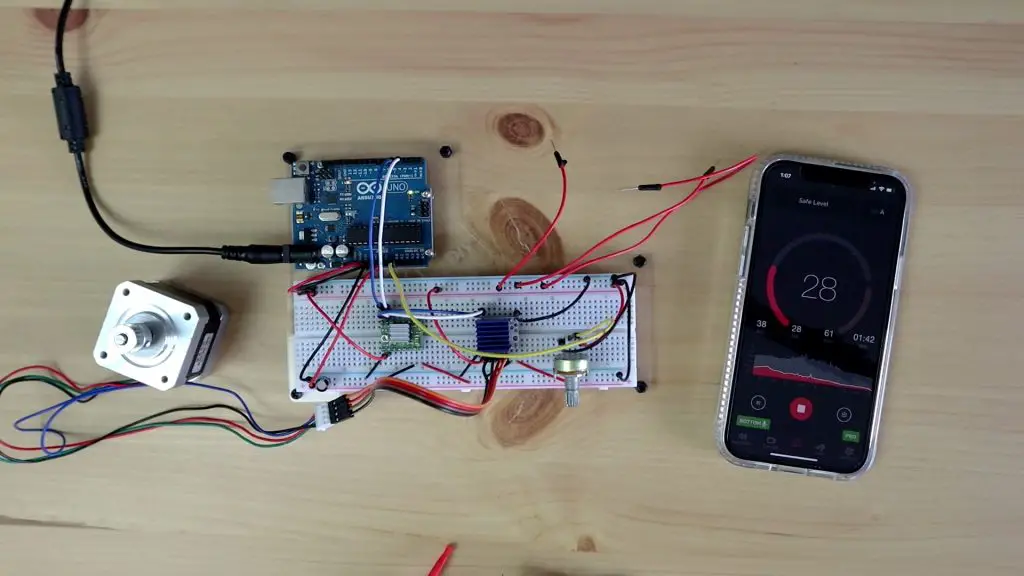
I’ve got a similar setup to the last test with the two drivers hooked up in the same way to an Arduino.
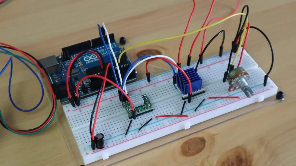
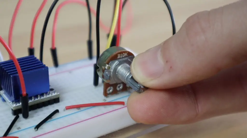
The drivers are both connected to digital outputs 3 and 4 on the Arduino for step and direction control respectively. So we just need to plug our motor into the one we want to test. I’ve also added a 10K potentiometer, connected to analogue pin A0, to adjust the time delay between step pulses, which in turn will control the motor speed.
The Arduino sketch is very basic, just assigning the pin modes in the setup function and then looping through reading in the potentiometer position and stepping the motor with the measured time delay.
//The DIY Life
//Michael Klements
//30 April 2020

int stepPin = 3;          //Define travel stepper motor step pin
int dirPin = 4;           //Define travel stepper motor direction pin
int motSpeed = 5;         //Initial motor speed (delay between pules, so a smaller delay is faster)

void setup()
{
  pinMode(stepPin, OUTPUT);                 //Define pins and set direction
  pinMode(dirPin, OUTPUT);
  digitalWrite(dirPin, HIGH);
}

void loop()
{
  motSpeed = map(analogRead(A0),0,1023,50,1);           //Read in potentiometer value from A0, map to a delay between 1 and 50 milliseconds
  digitalWrite(stepPin, HIGH);                          //Step the motor with the set delay
  delay(motSpeed);
  digitalWrite(stepPin, LOW);
  delay(motSpeed);
}Testing the Waveforms from the A4988 and TMC2208 Stepper Motor Drivers
We’re going to start with the A4988 driver by first taking a look at the sound level at different speeds.
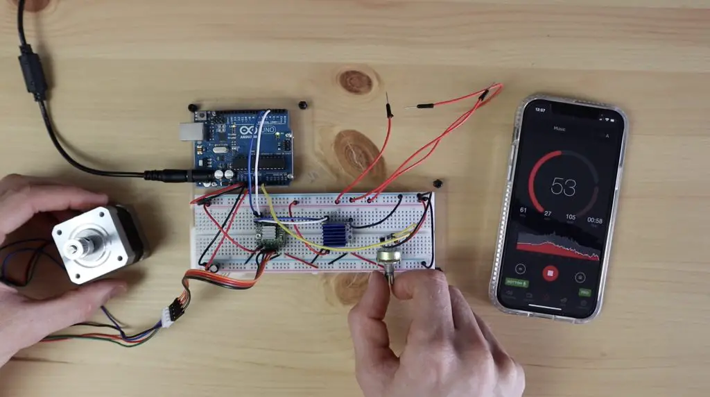
The sound level throughout the range of speeds was an average of around 50-60dB. The sound was obviously being amplified by the wooden desk and wouldn’t be that loud with a proper vibration damping mount, but this way you get a good idea of the improvement.
To measure the waveform I’m going to use this Pokit multimeter and oscilloscope and I’m going to connect it in series with one of the motor coils to measure the current flowing through the motor coil.
In the video, you may notice that the motor sounds a bit weird when it’s connected and the oscilloscope isn’t measuring anything. This is because the oscilloscope opens the circuit when it isn’t taking readings. So the motor effectively only has one coil connected to the drive. You’ll see the shaft isn’t turning any more and is just sort of jumping in the same spot. So we’re only interested in the sound the motor makes during readings after I’ve pushed the red record button.
A4988 in Full Step Mode
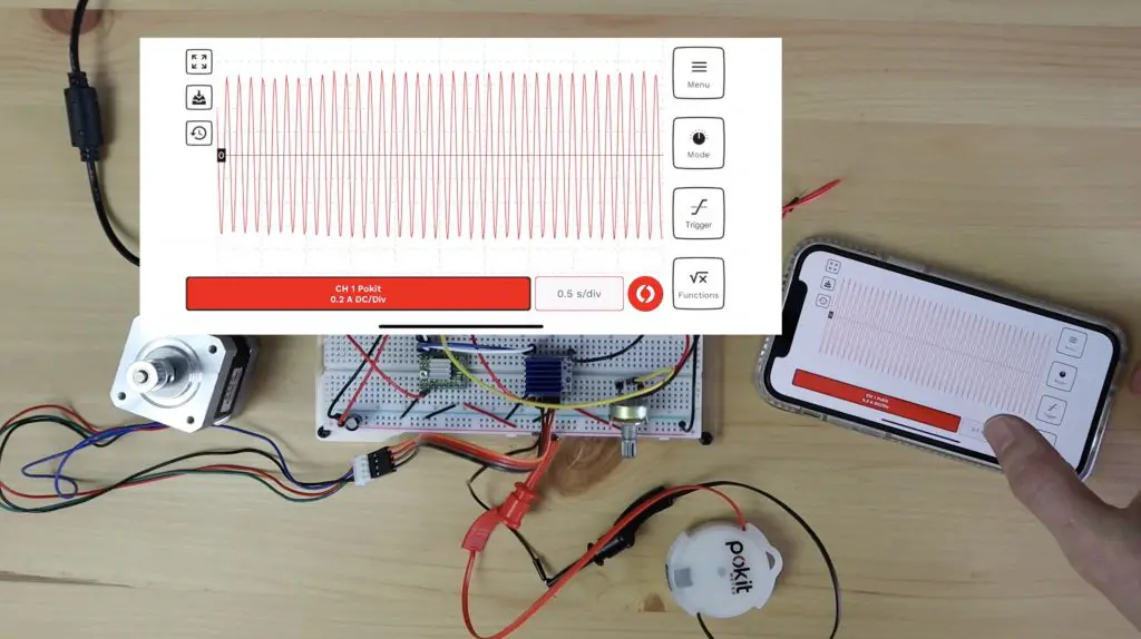
With the A4988 driver running in standard full-step mode, you can quite clearly see that the driver is producing a very square wave.
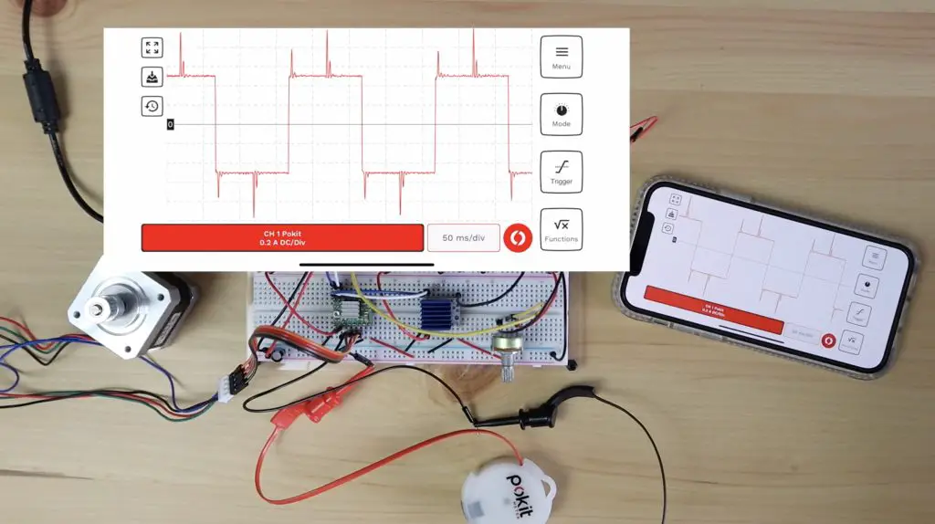
It also doesn’t matter if we increase the motor speed, we still get a similar square wave that just repeats more often in the same timeframe. So this waveform is obviously quite far from a sine wave and therefore produces the most vibration within the motor, leading to the most noise being generated.
That’s not the end of the road for the A4988 driver, it can actually produce somewhat of a sine wave through microstepping.
Microstepping is essentially the ability for the driver to partially energise the coils to position the rotor in positions between the two poles, and it does so in a way that resembles a sine wave. So the most positions (microsteps) you can do between each pole, the better your sine wave is going to look.
The A4988 can do half, quarter, eighth or sixteenth step microstepping by pulling a combination of three pins high. So let’s see what those look like – we’ll start with half step mode.
A4988 in Half Step Mode
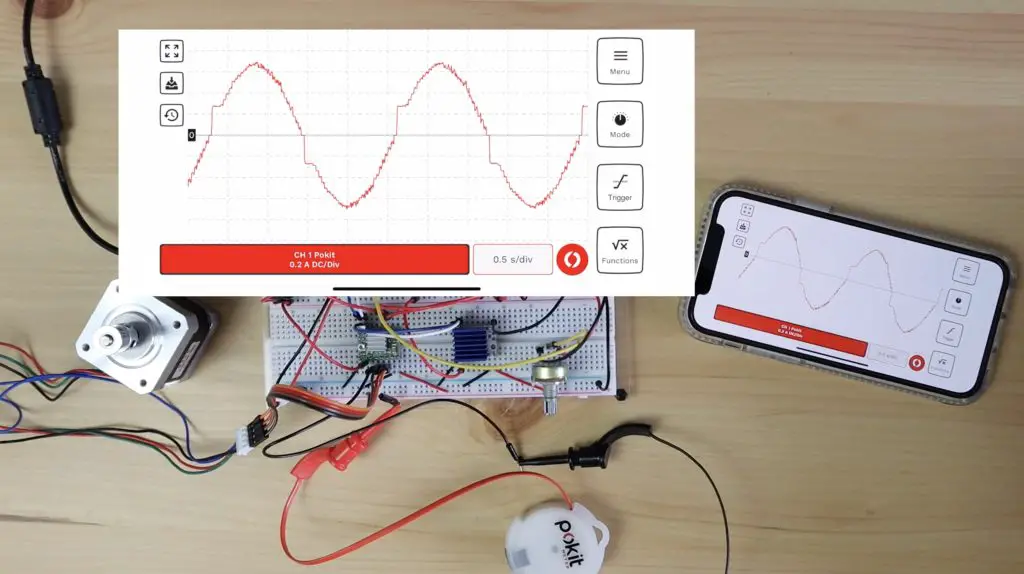
With the A4988 driver running in half step mode, we now got something that is starting to look a bit like a sine wave – but there is obviously still a lot of room for improvement.
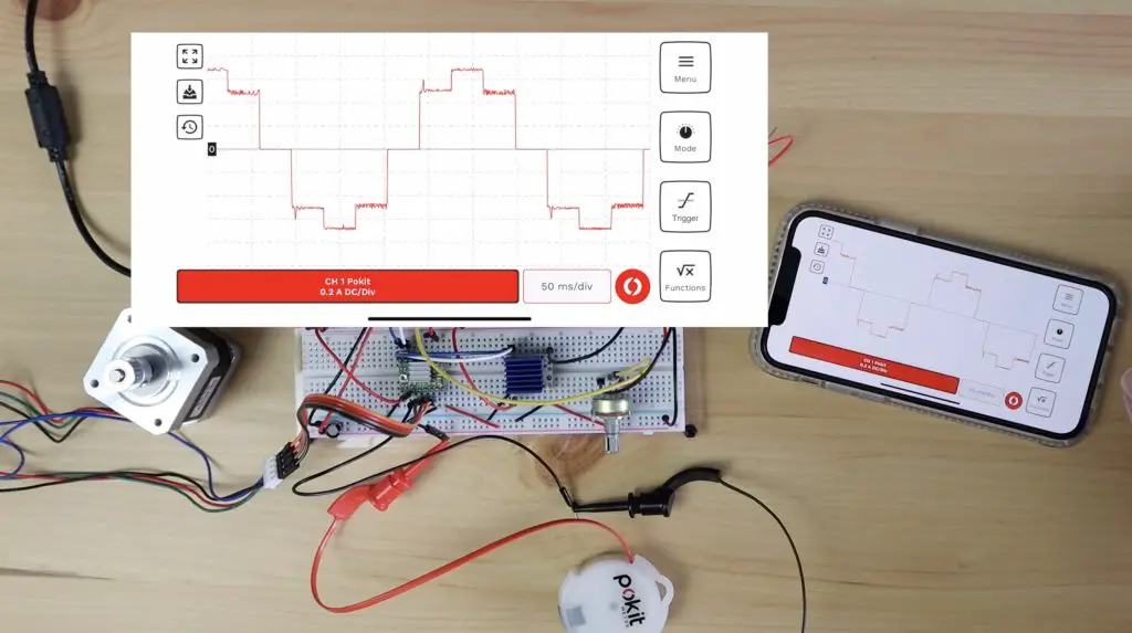
The motor also sounded like it was running a little smoother than in full step mode. Looking at the waveform produced, you can clearly see two steps on our sine wave above and below 0.
A4988 in Eighth Step Mode
Now let’s try and improve upon our results with eighth step mode. So in this test, we should now have eight increments between the zero and the maximum on our sine wave.

The first thing you’ll notice is that the sine wave doesn’t fit into our timeframe anymore. That’s because the driver now only moves 1 micro step for each pulse, so our motor is effectively moving 8 times slower than it was in full step mode. So, for example, a motor with 200 steps per revolution running in eighth step mode will now have 1600 steps per revolution.

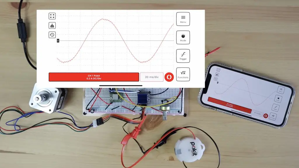
If we adjust the time scale, we can see our full sine wave and we’ll also notice that our motor is again moving smoother, and slower than it was when in half step mode.
A4988 in Sixteenth Step Mode
Lastly lets try sixteenth step mode, which is the most that this A4988 driver can do.
You’ll again notice that the motor is moving half as fast as eight step mode and we’re getting a wave that’s now looking a lot like a sine wave.
That’s now the end of the road for our A4988 driver. The micro stepping has made it run much smoother and a bit quieter, but it’s still quite noisy. So let’s swap over to our TMC2208 driver now.
TMC2208 Running In Legacy Mode
For compatibility with the A4988 driver’s code, we’re going to be running the TMC2208 driver in Legacy Mode. This mode essentially allows the driver to act as a drop-in replacement for the A4988 driver.
If you watched the video, at this stage you probably hadn’t noticed that the motor was running. That’s obviously a significant improvement over the A4988 drivers that produced around 50-60dB. The TMC2208 driver operates nearly silently, even when you change the speed.
A big part of how it does this is that the TMC drivers produce 256 microsteps, so sixteen times more than what the A4988 drivers do.
Let’s now hook up the oscilloscope and see what the waveform look like.
As with the previous test, the motor makes a bit of noise when the oscilloscope isn’t taking measurements as its only got a single pole connected, so it’s jumping back and fourth around the same pole. It does however go silent again when the oscilloscope is running.
As with the A4988 driver, if we change up the speed we still get the same smooth sine wave, it just repeats more often in the same time interval.
So you can see that’s a significantly improved sine wave over even the best one that the A4988 driver was able to produce.
Finals Thoughts on the TMC2208 Motor Driver Test
So now you have a basic understanding of what the TMC2208 drivers do differently to run almost silently.
As for any drawbacks. There are two primary ones.
One is a slight reduction in incremental torque, which is not usually an issue unless you’re operating near the motors torque limitations.
The second is not so much to do with the motor but to do with the microcontroller telling the driver what to do. As I’ve mentioned earlier, microstepping requires more pulses from the microcontroller to move the motor a full step. So, running in sixteenth step mode requires your microcontroller to output 16 times more pulses than it would need to in full-step mode. If you’re doing this across multiple motors or while doing other tasks, your controller quickly gets bogged down just keeping the motors running and may not be able to keep up.
Out of interest, during the tests, I was running the drivers with a 12V supply to the motor.
That’s it for today, I hope you’ve learned something and found this explanation useful. Let me know in the comments section what you’ve used these drivers for and check out some of my other projects for ideas.
Can you just swap those modules on a 3D printer without having to change firmware?
You’ll likely need to change the firmware to accomodate whatever micro stepping difference there might be between the two drivers.
This sounds like a fascinating experiment! I’m bummed the video is unavailable. I’ve always wondered about the sound diff between these drivers. Did you notice any difference in power consumption too? I once had a 3D printer with an A4988 that got pretty noisy.
This is super interesting! I had no idea there was such a difference in sound between these drivers. Have you noticed any difference in the motors’ performance aside from the noise?