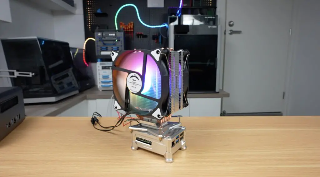
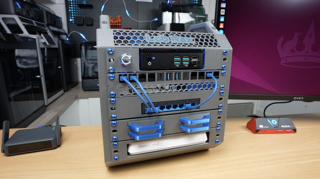
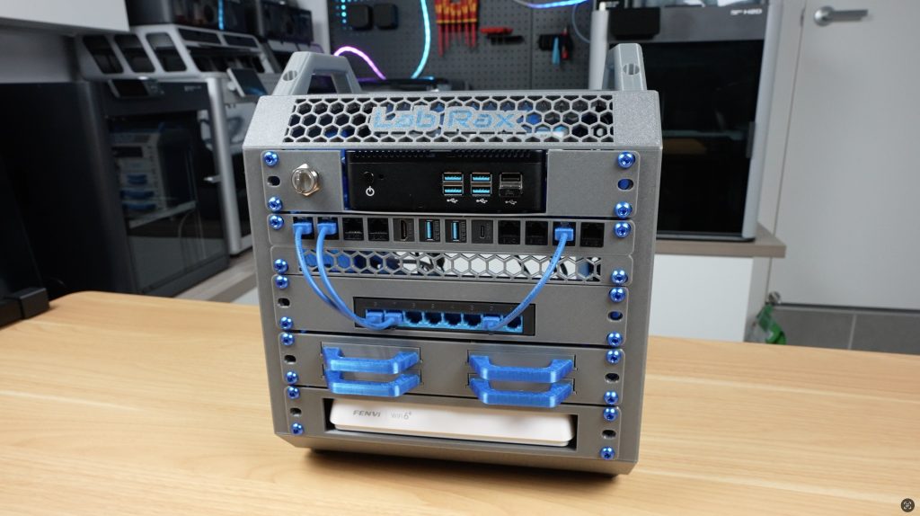
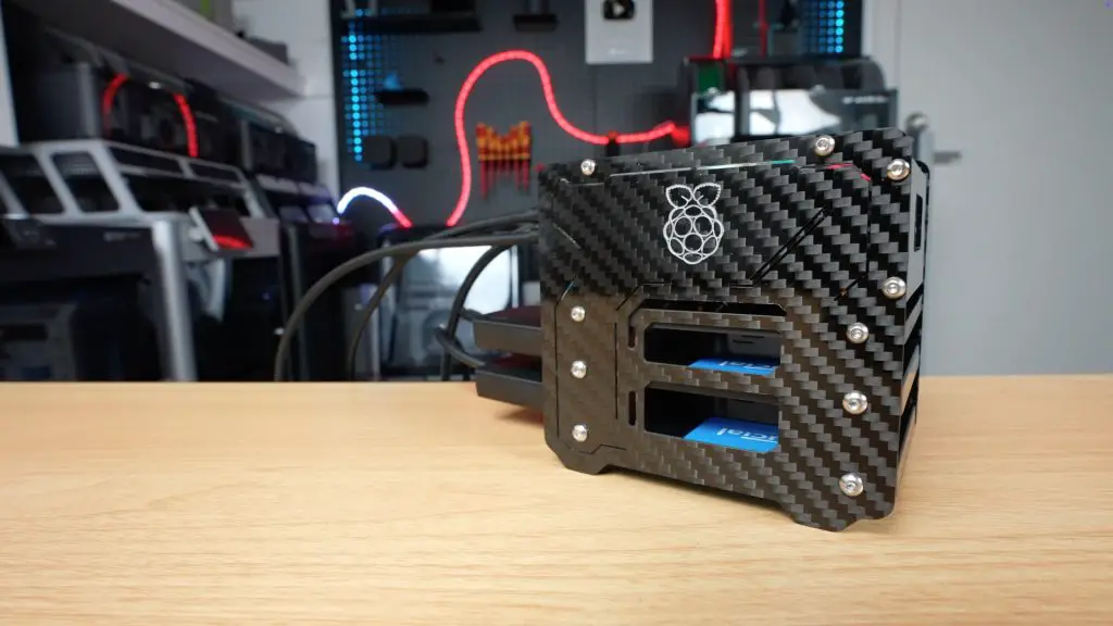
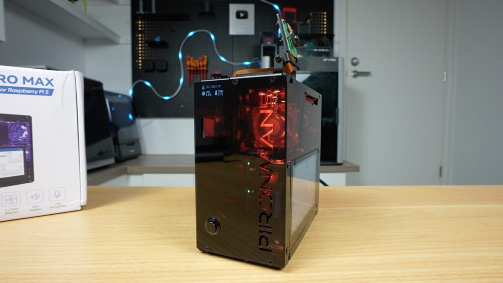
Today, we’re taking a look at what might be the most over-the-top Raspberry Pi 5 case I’ve tried out so far – the Pironman 5 Pro Max by Sunfounder. At first glance, it looks like it’s just a bigger version of the Pironman 5 Max that I reviewed last year.
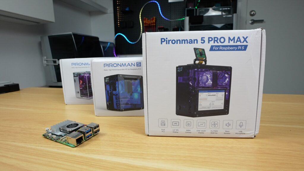
You’ve still got a very similar aluminium shell with acrylic panels, dual NVMe support, a tower cooler and RGB fans, and the same general layout, but the big changes are around standalone usability. We now get a 4.3″ touchscreen, dual speakers, a USB microphone, and a camera module with a dedicated mount. So this is no longer just a Pi in a nice case, it’s more like a self-contained mini computer or AI terminal.
These features come with an increase in price, though, pushing this case up to $146. So let’s get it assembled and find out if the additional features are worth it.
Here’s my video review of the case. Read on for the written review:
Where To Buy The Pironman 5 Pro Max & Test Components
- Pironman 5 Pro Max – Buy Here
- Pironman 5 Max – Buy Here
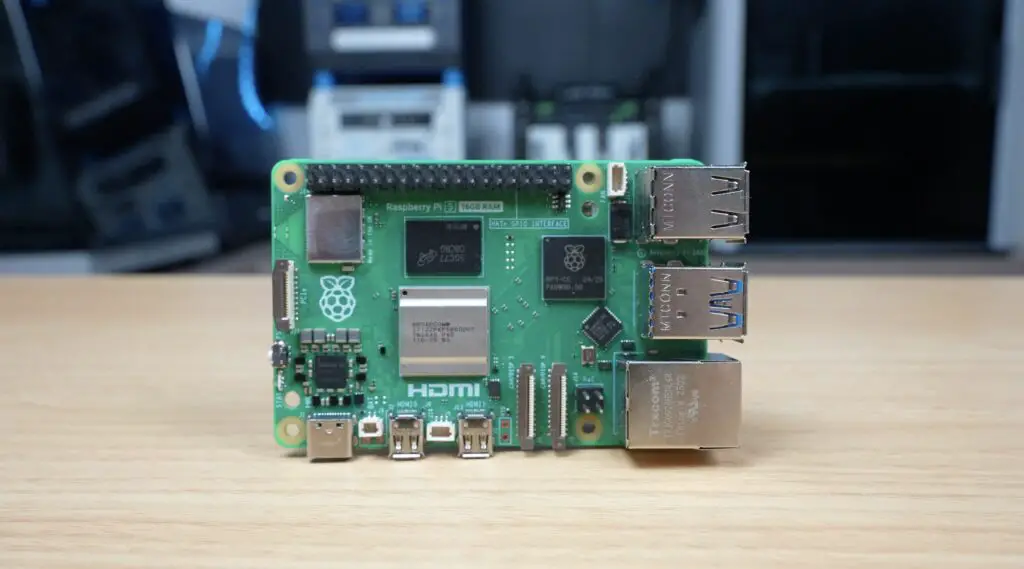
- Raspberry Pi 5 – Buy Here
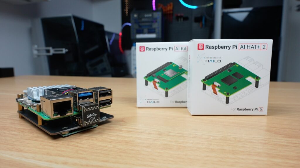
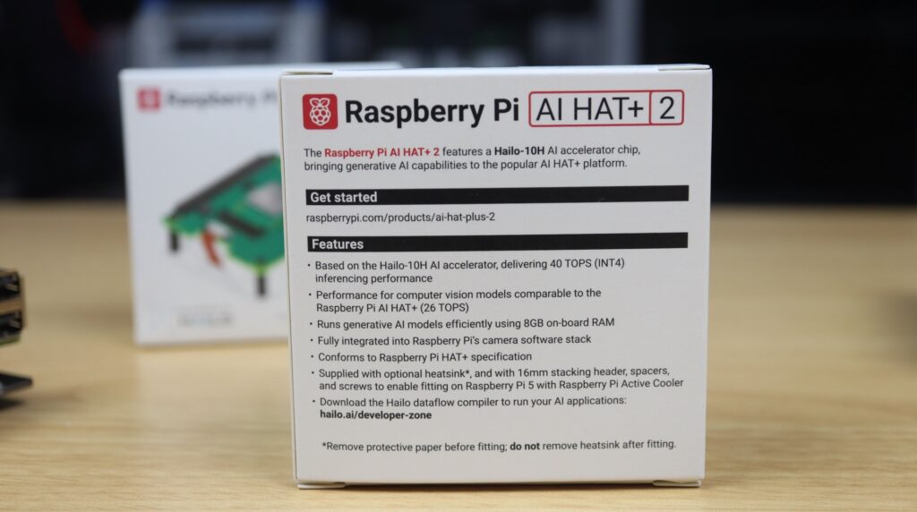
- Raspberry Pi AI Kit (Hailo-8L Module) – Buy Here
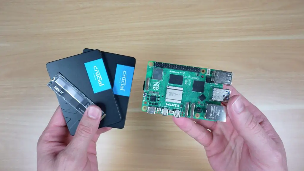
- Lexar NVMe SSD – Buy Here
- Pi 5 USB C Power Supply – Buy Here
Some of the above parts are affiliate links. By purchasing products through the above links, you’ll be supporting my projects, at no additional cost to you.
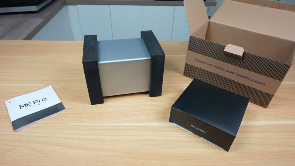
Unboxing The Pironman 5 Pro Max
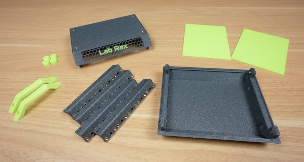
The case comes in a similar kit to the Max.
Inside the box you’ve got, the aluminium panels, acrylic side panels, cooling hardware, NVMe and expansion boards, an OLED display and a lot of screws. There’s also a touchscreen, a camera module, two small speakers, and a USB microphone.
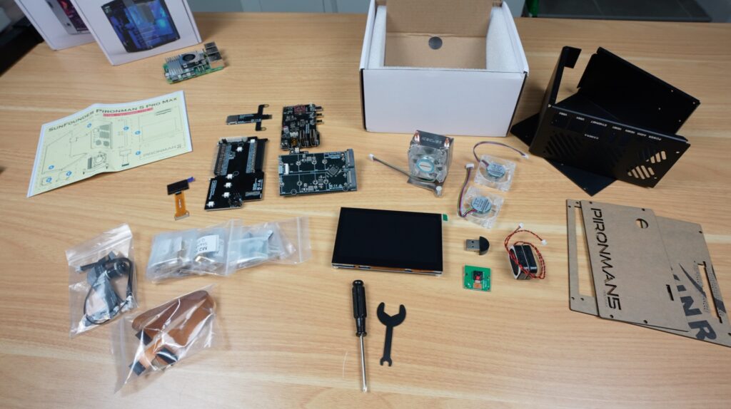
So there are a few more components to install compared to the Max.
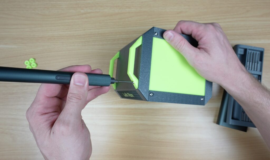
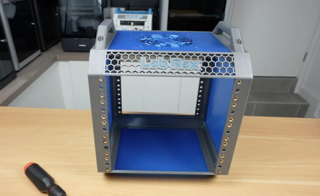
Assembling The Case
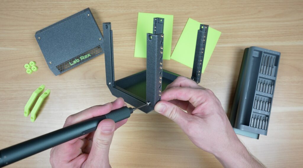
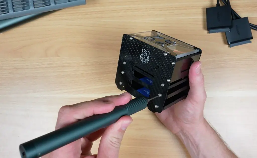
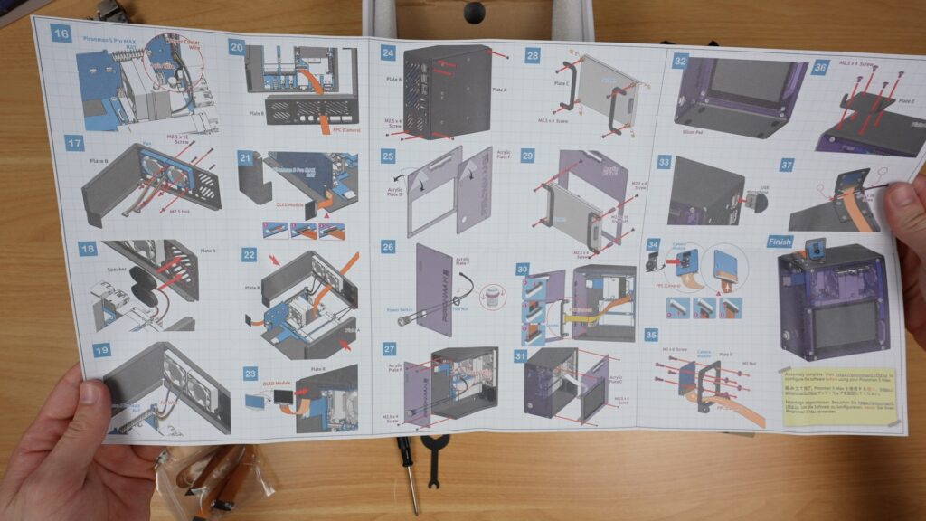
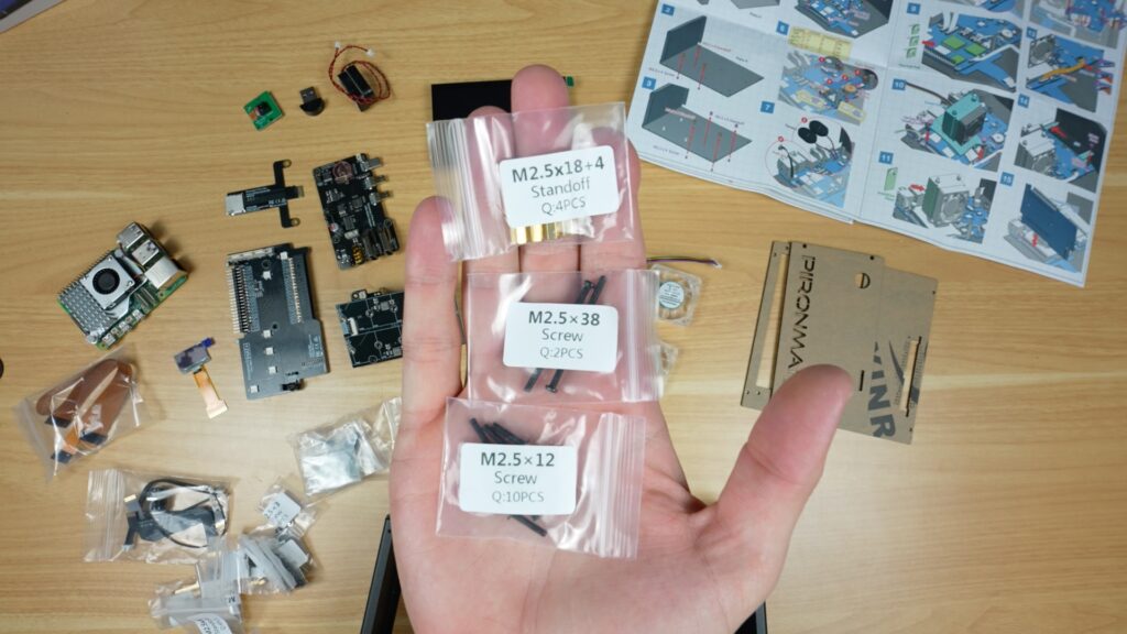
Assembly is very similar overall to the Prionman 5 and 5 Max, and is again done by following a large picture-guided instruction sheet. All of the screws are also well labelled, so it’s really easy to do. They even include a small screwdriver.
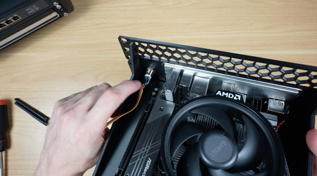
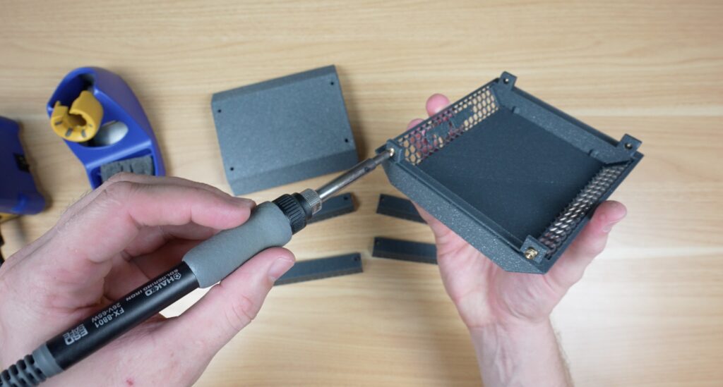
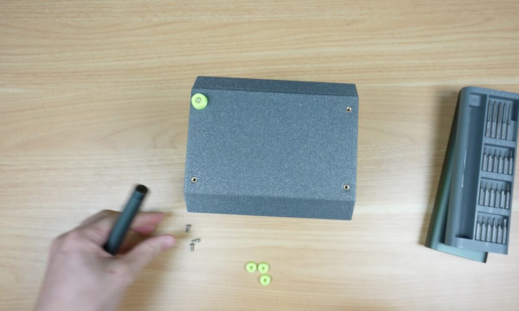
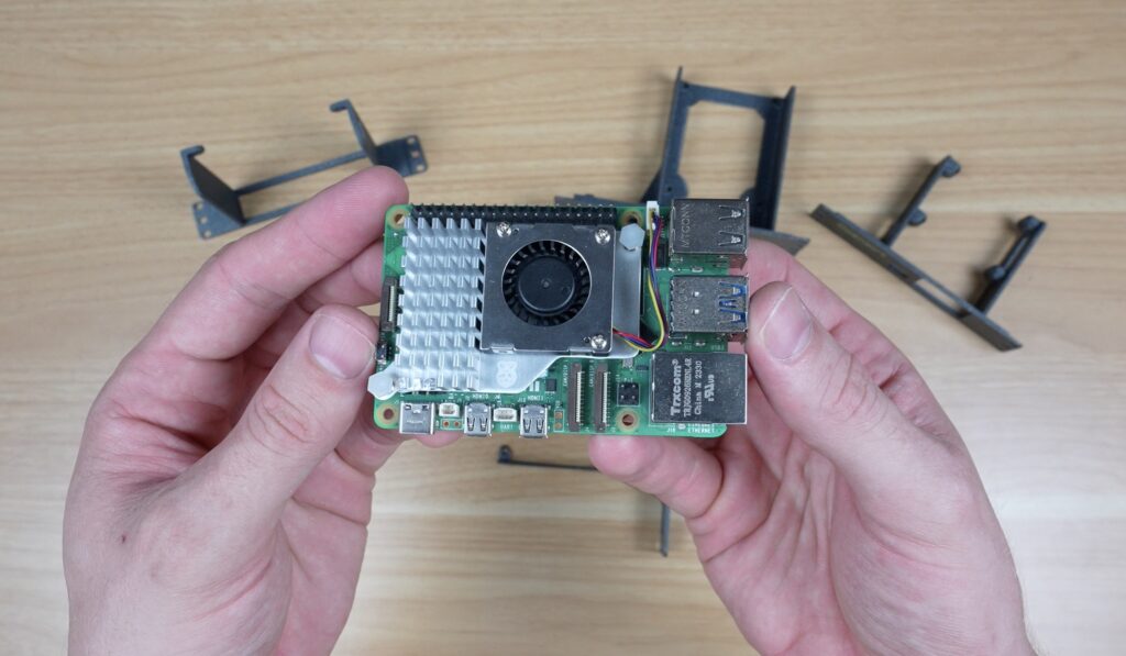
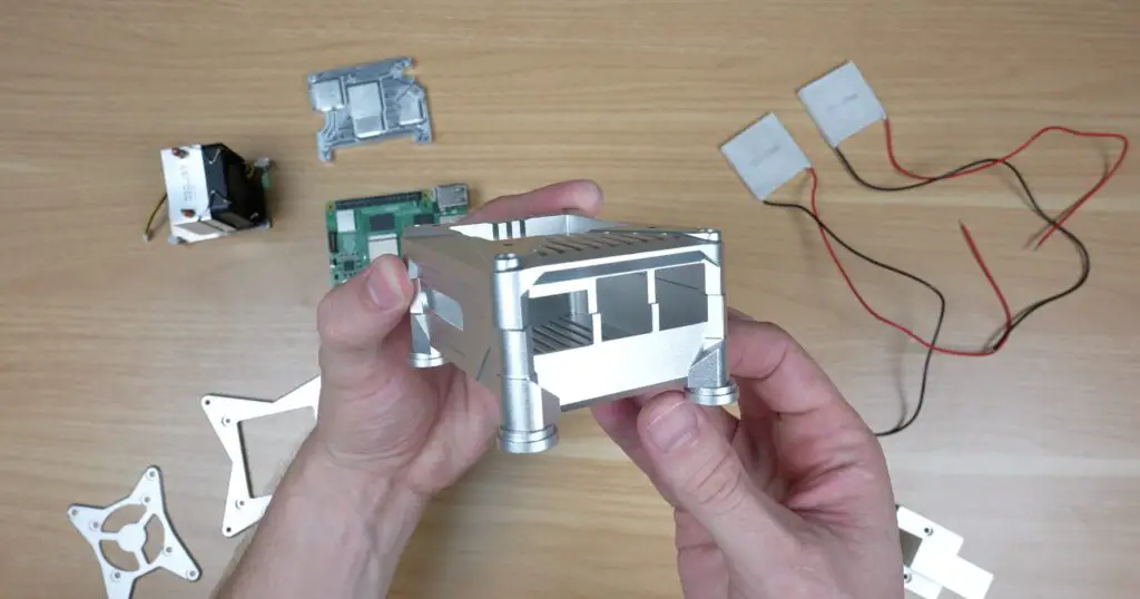
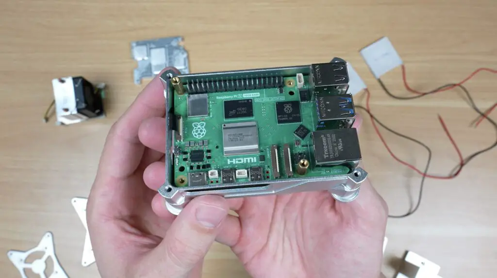
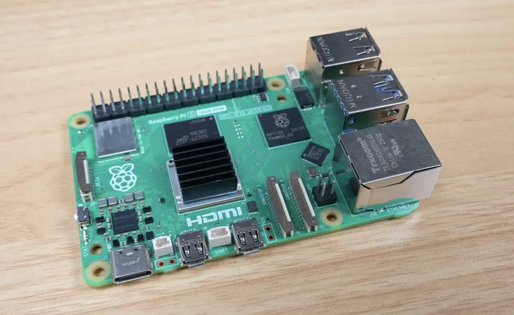
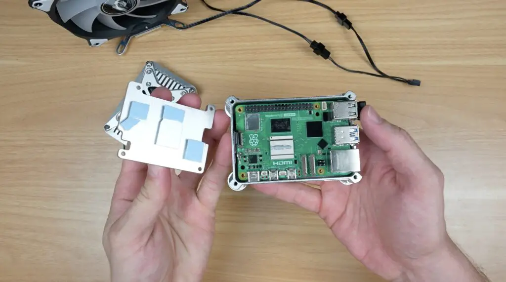
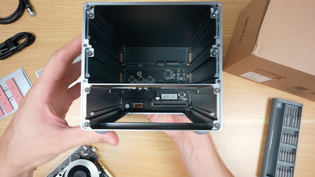
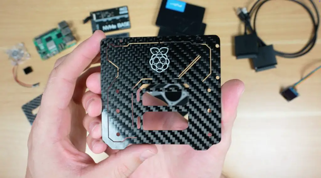
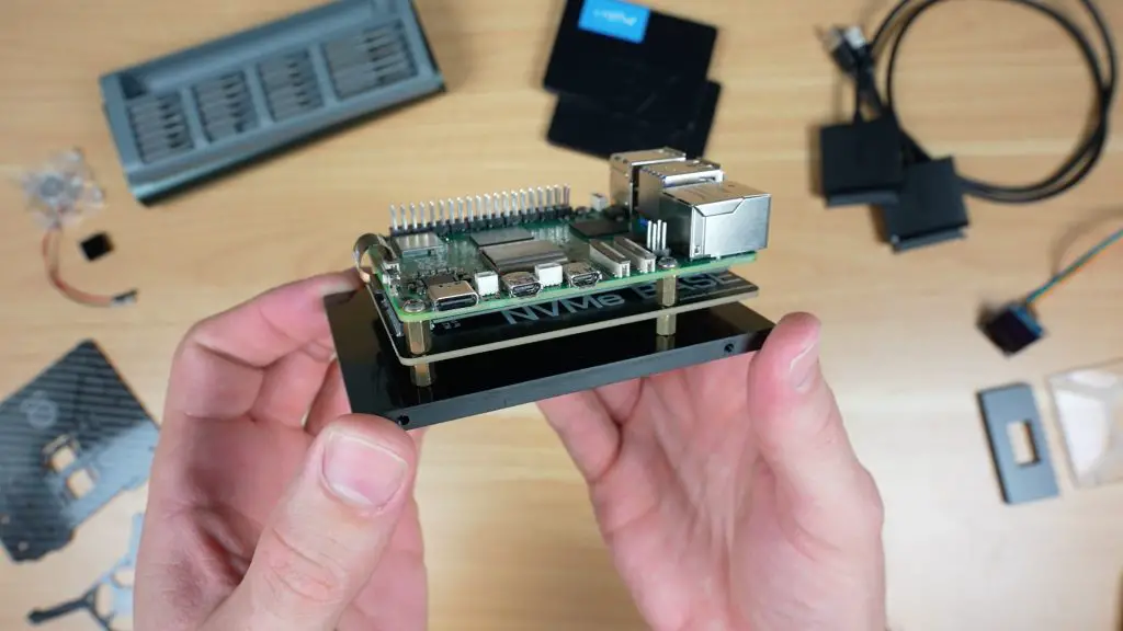
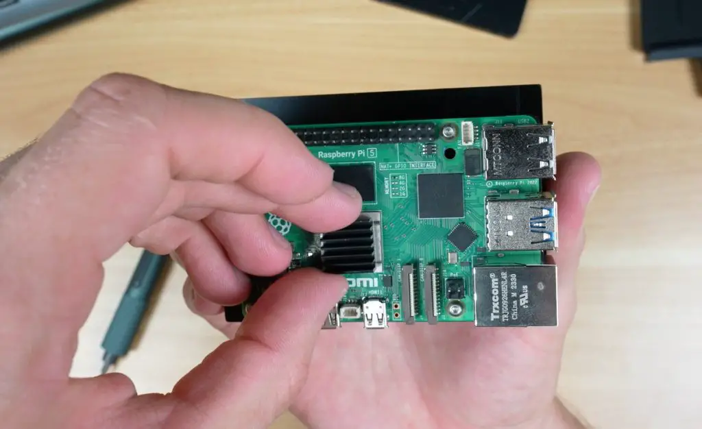
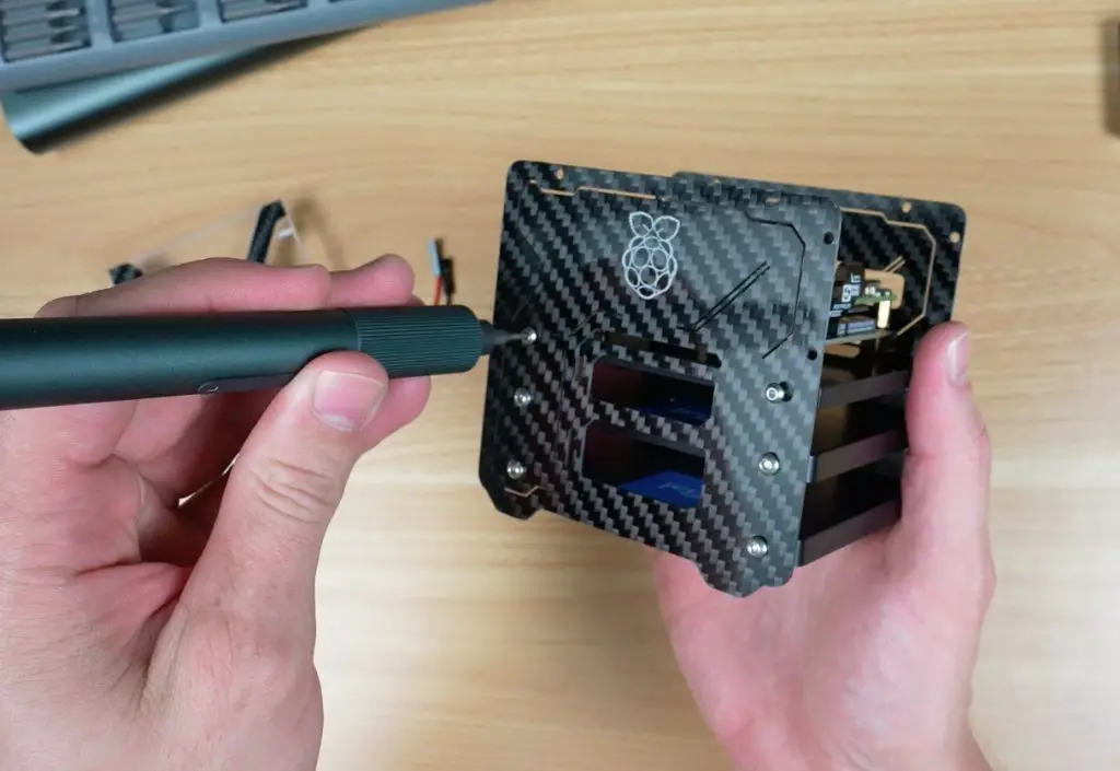
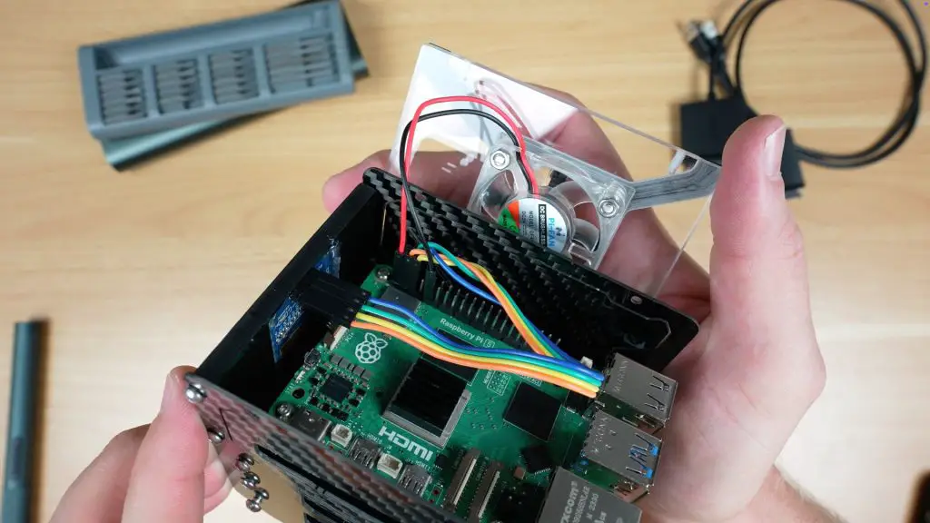
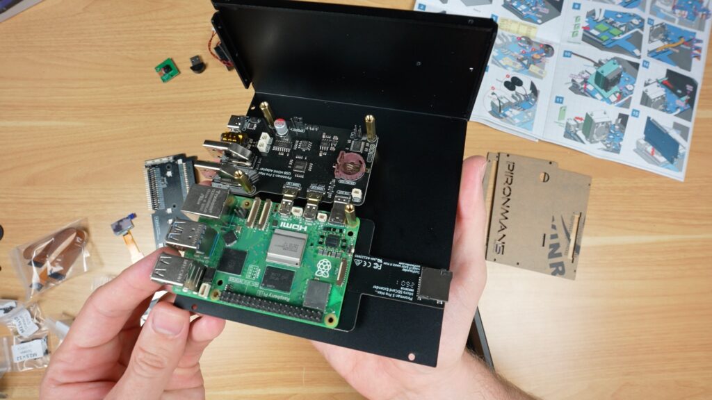
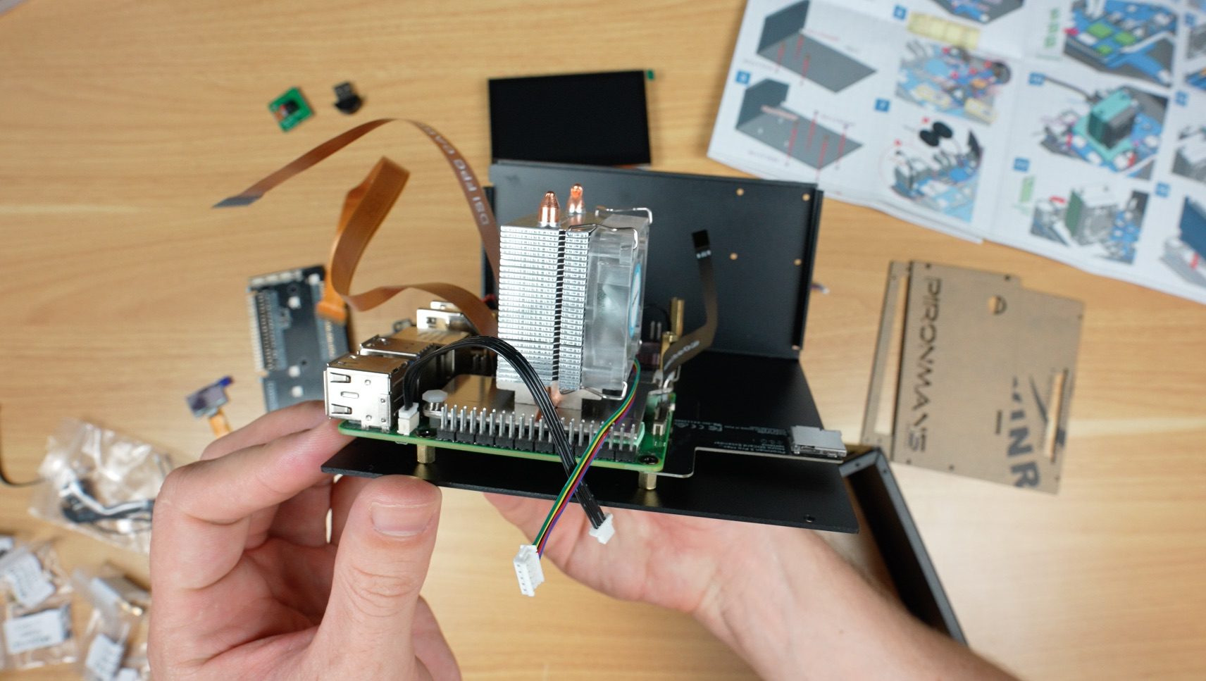
Like with the other Pironman series cases, you start off by installing the standoffs on one half of the case. Then connect some expansion boards to your Raspberry Pi 5 and screw that into the case.
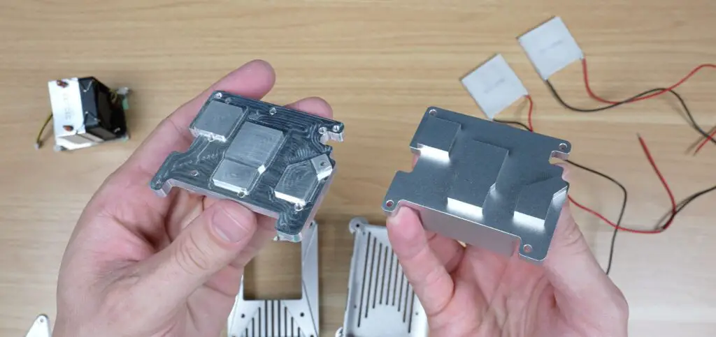
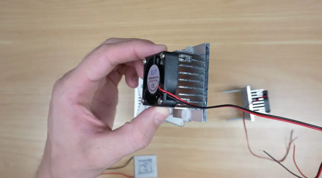
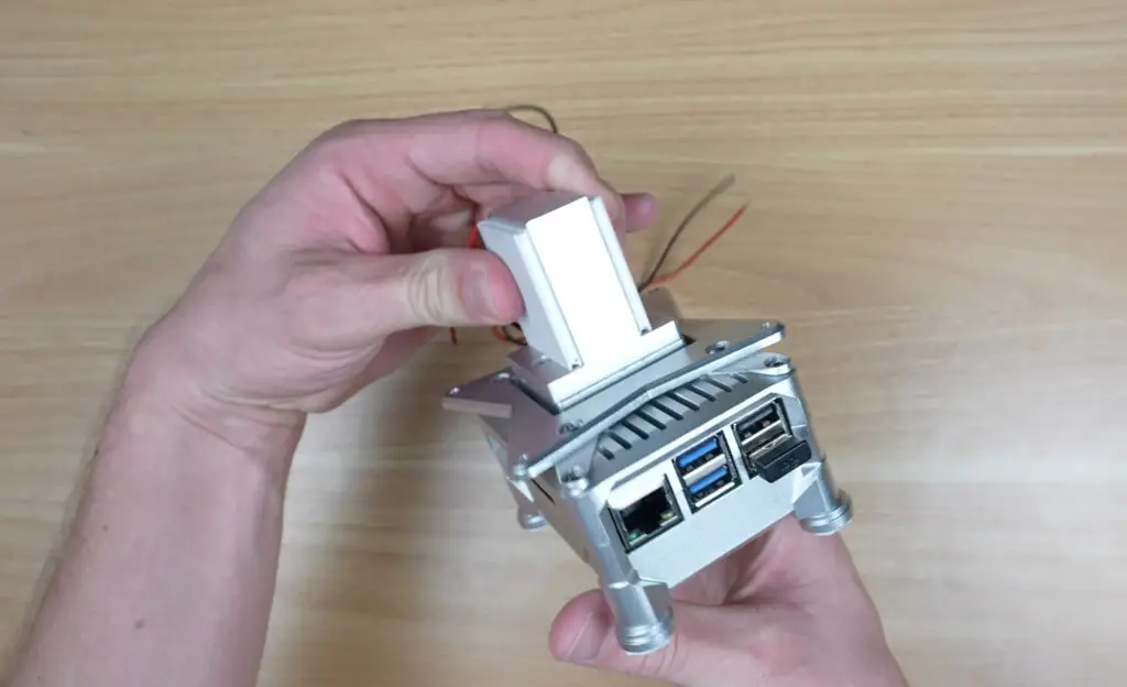
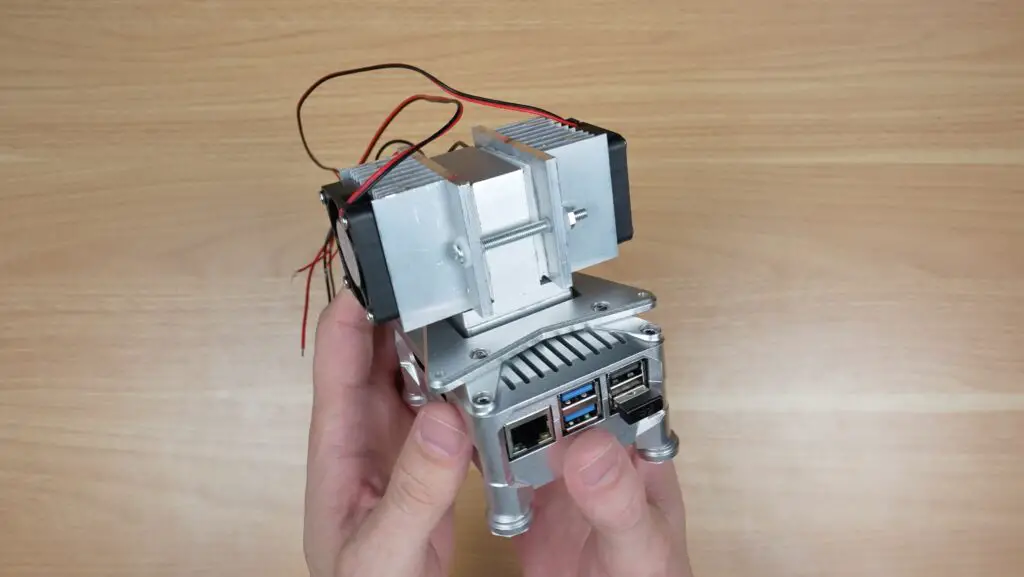
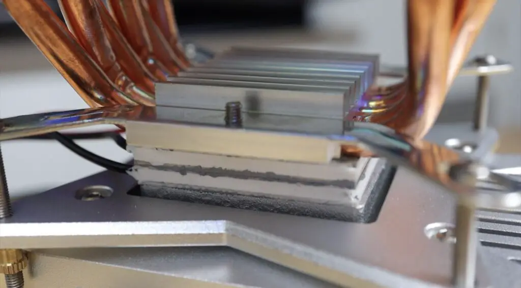
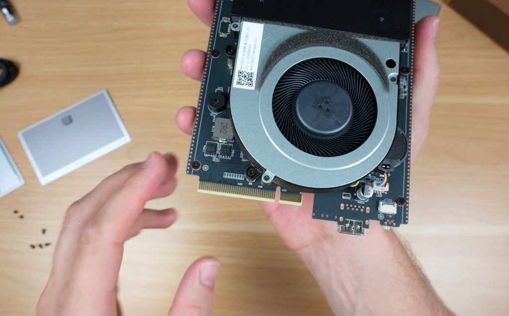
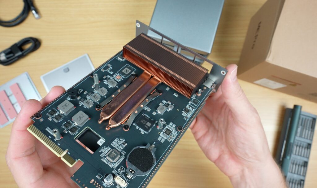
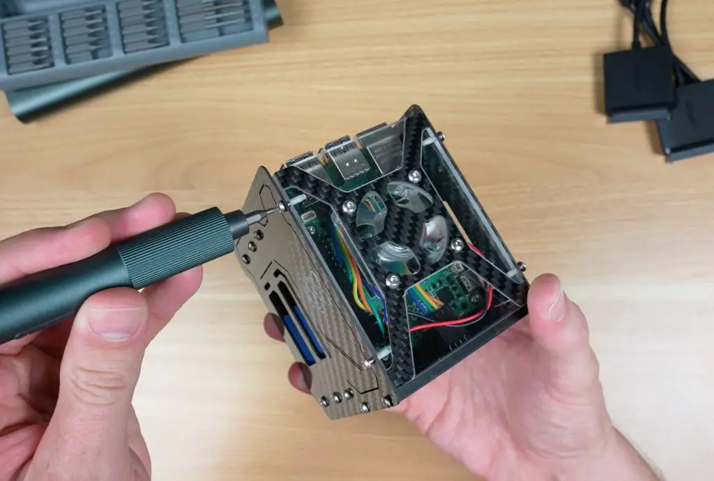
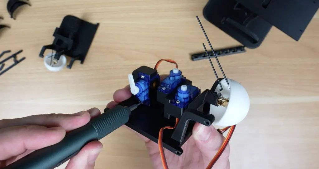
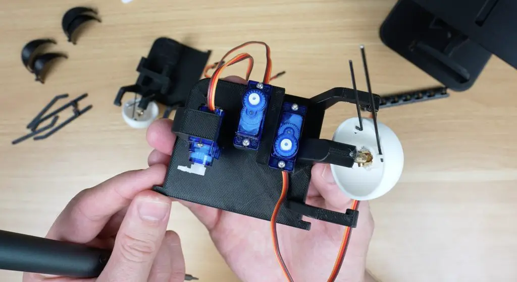
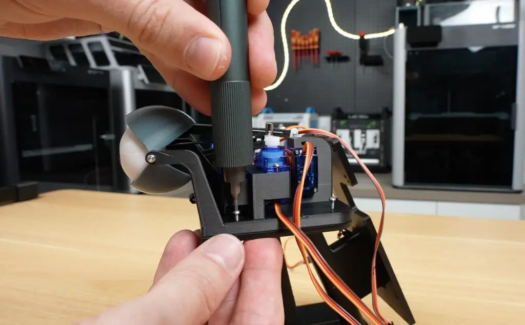
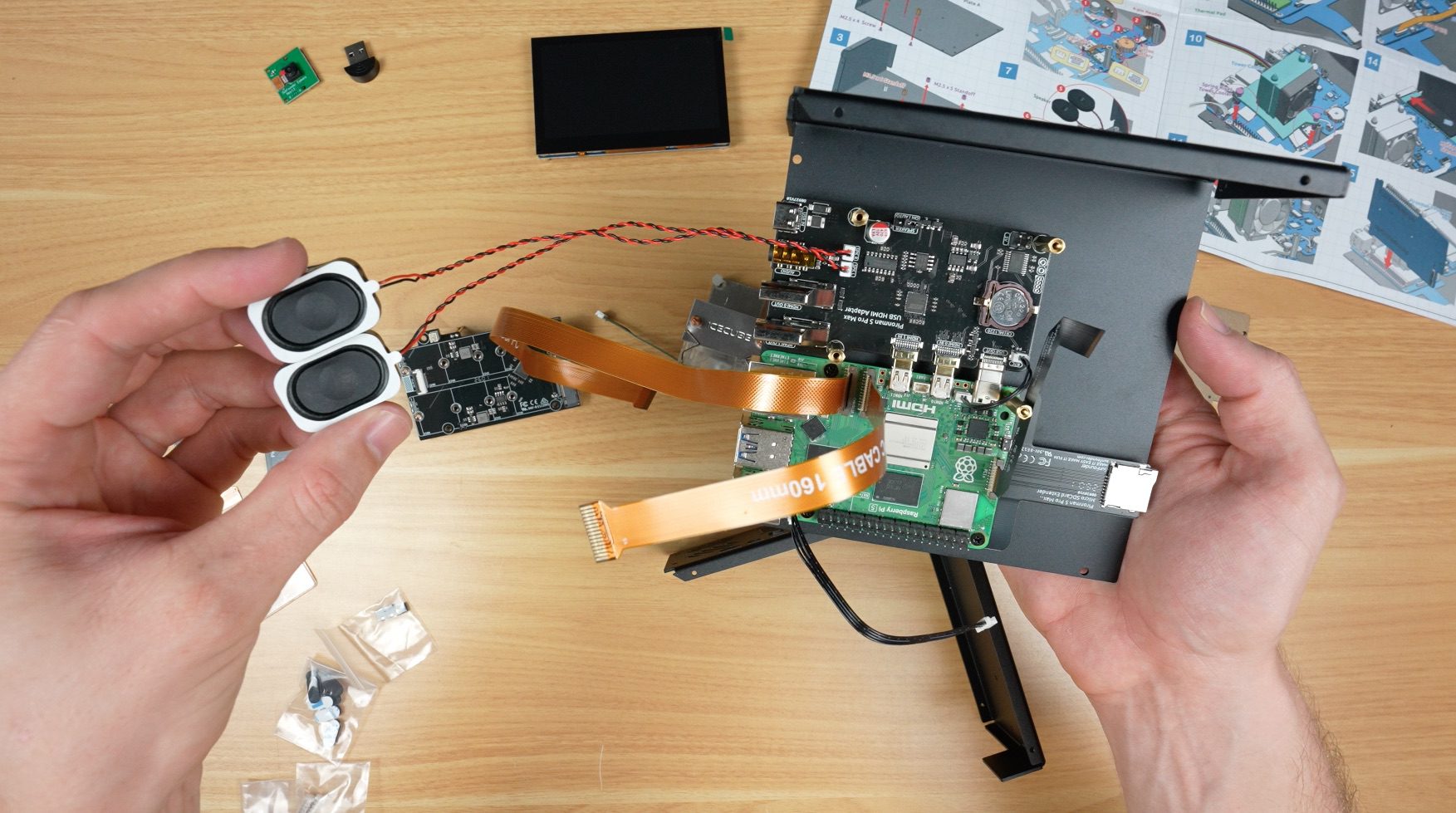
Next up, you install some cables and the speakers, and then comes the tower cooler. You install the thermal pads onto the CPU and surrounding heat-producing components, then mount the cooler using the spring-loaded push pins.
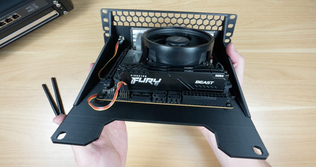
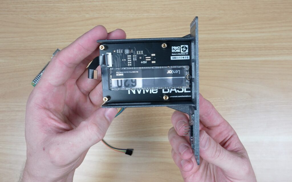
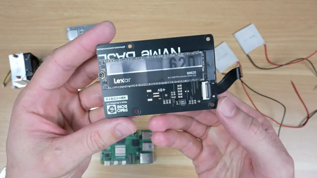
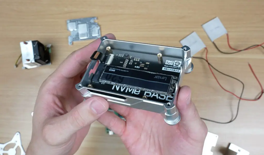
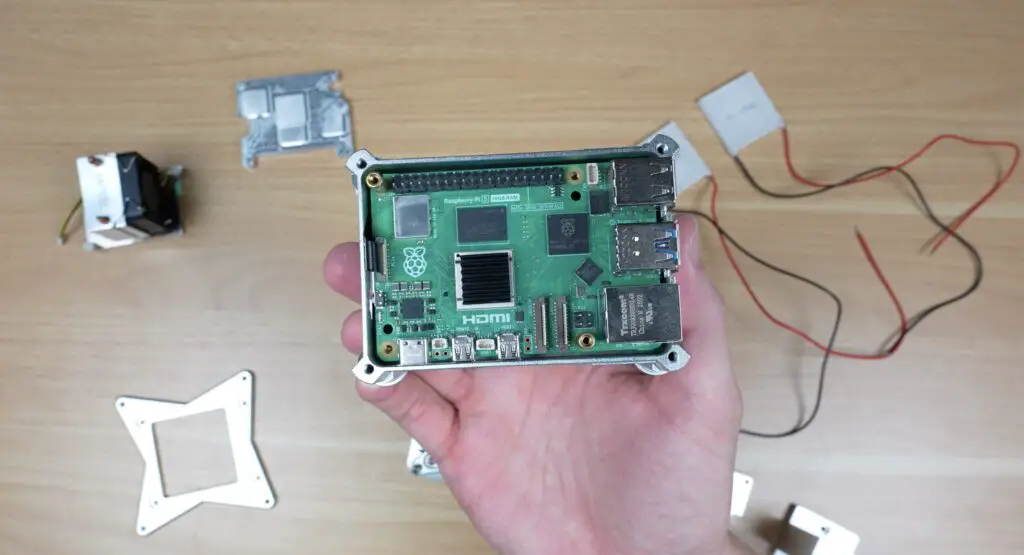
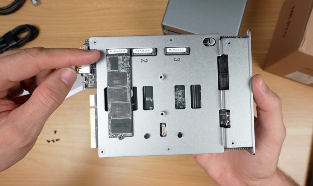
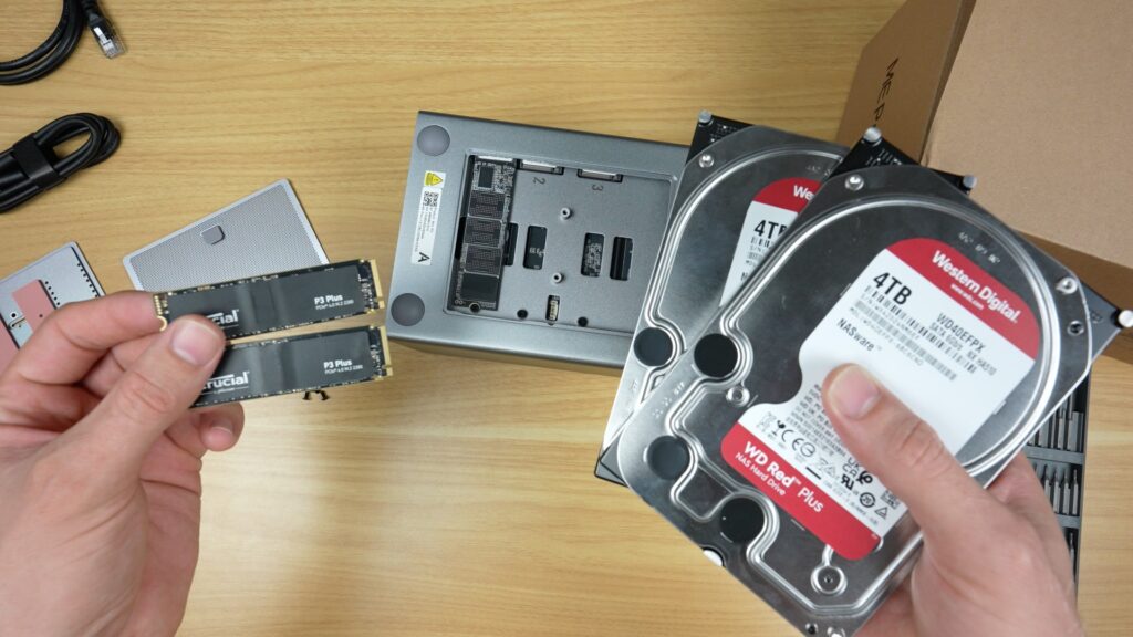
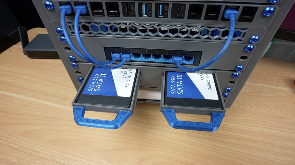
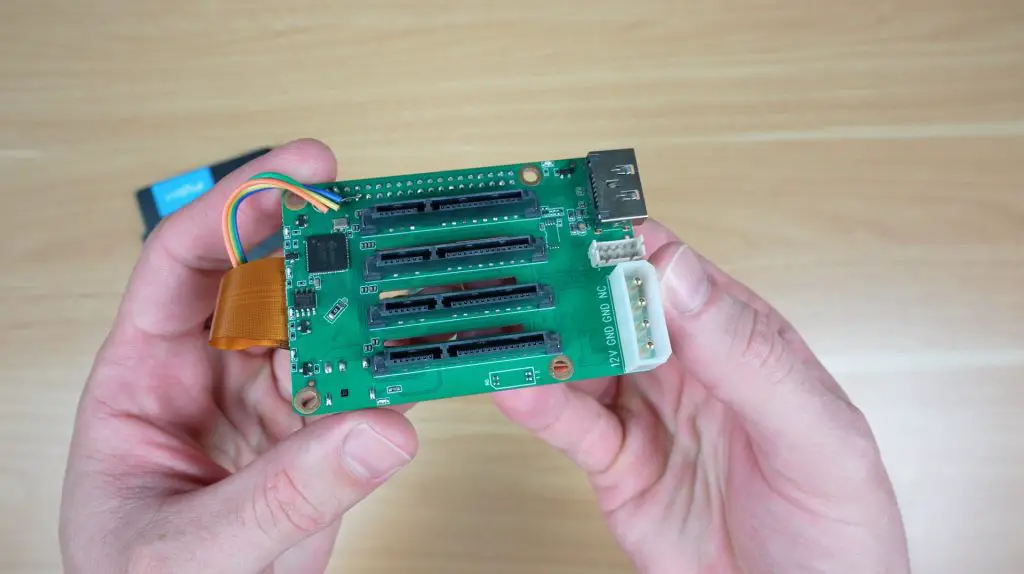
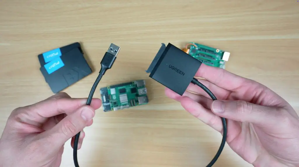
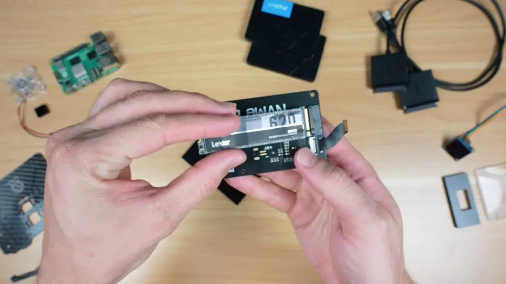
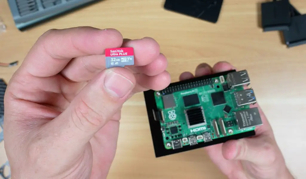
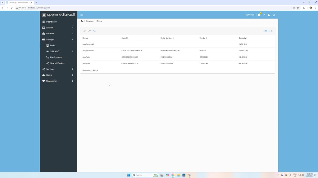
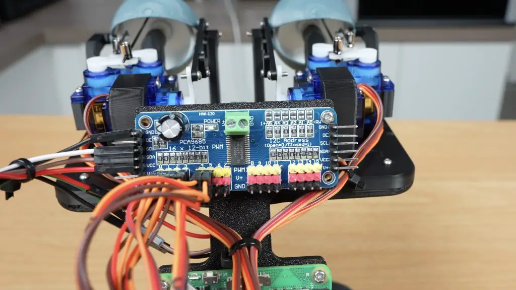
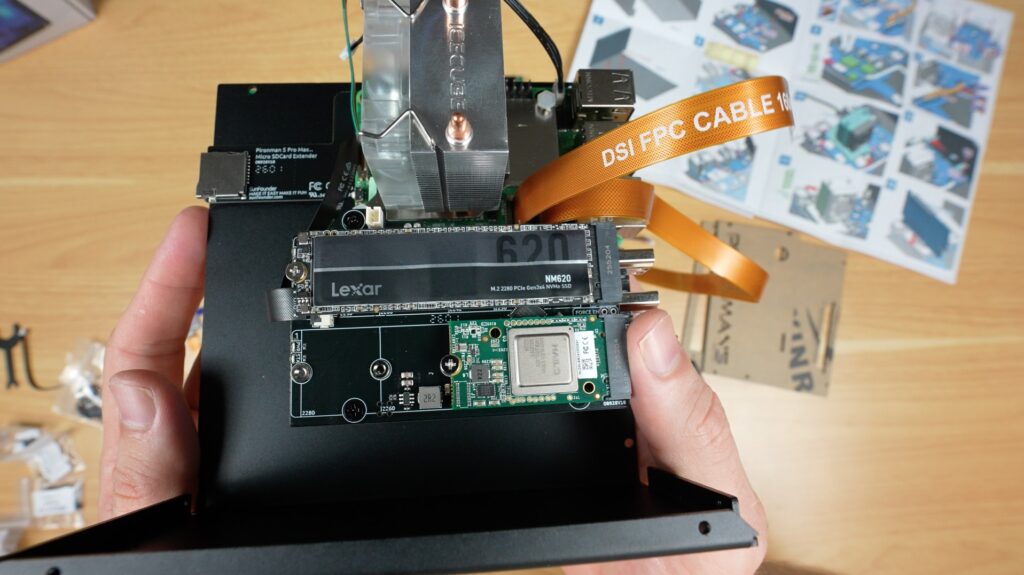
After that, you install the dual NVMe adaptor and your SSDs or an SSD and AI accelerator like the Hailo-8L. If you’re using your NVMe drive as the boot drive, remember to flash your OS to it before installing it.
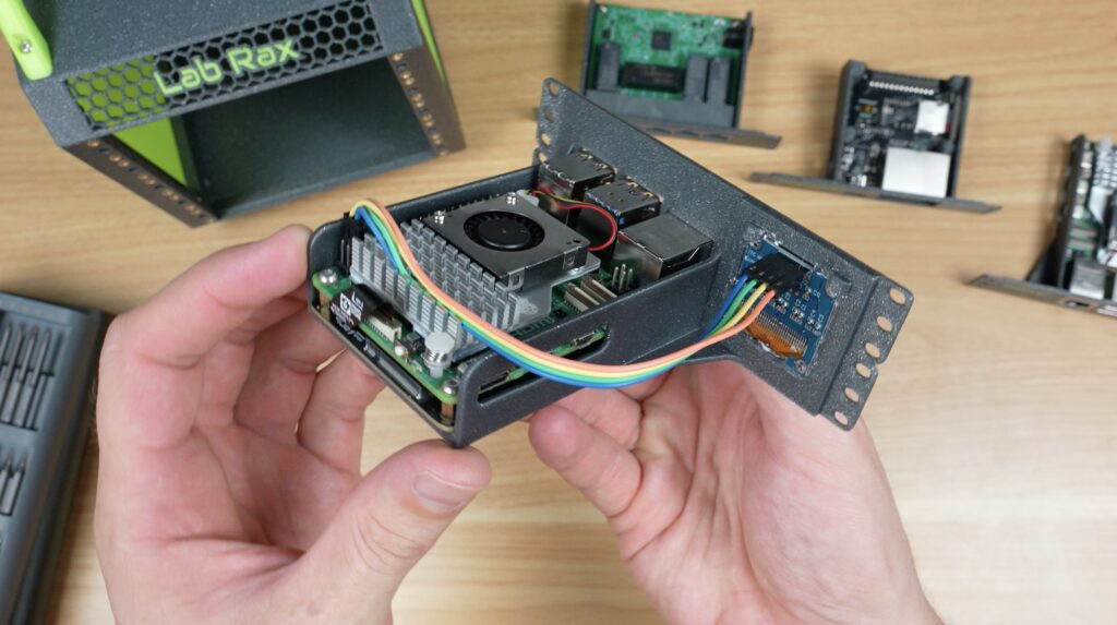
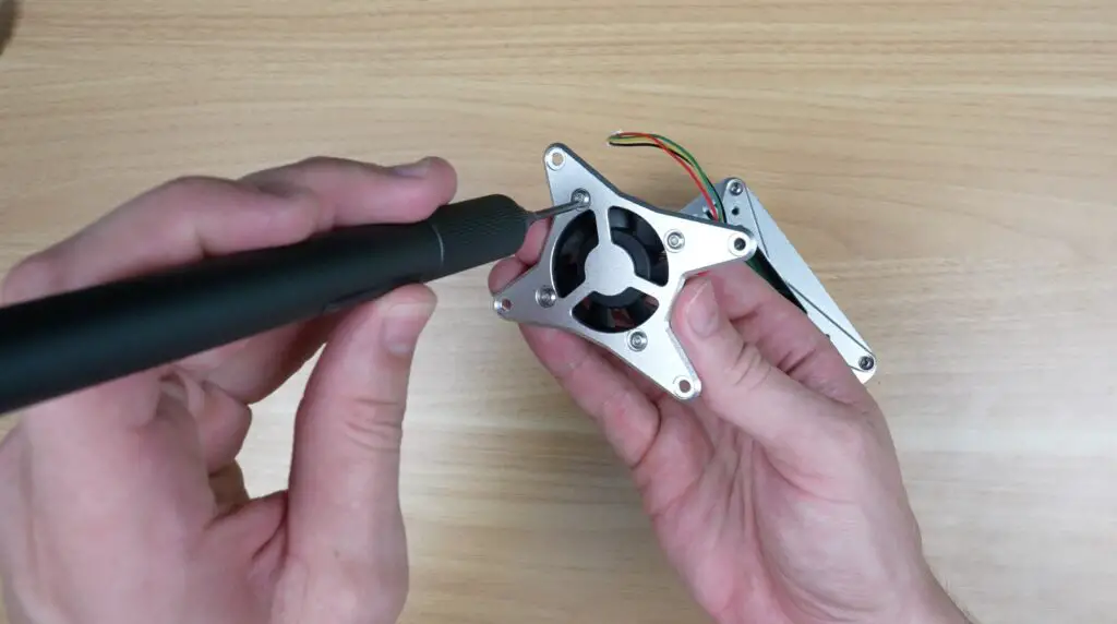
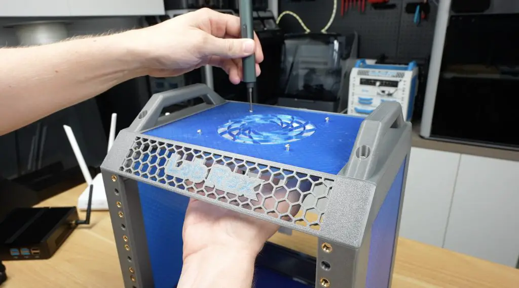
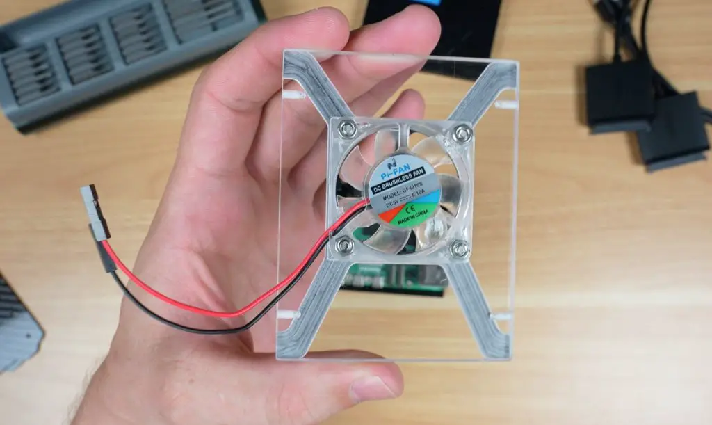
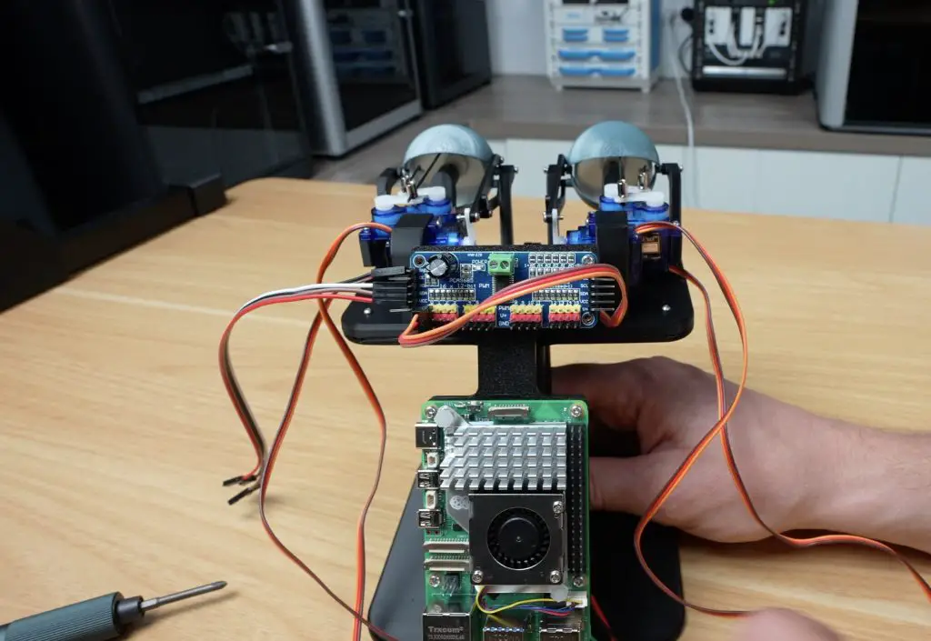
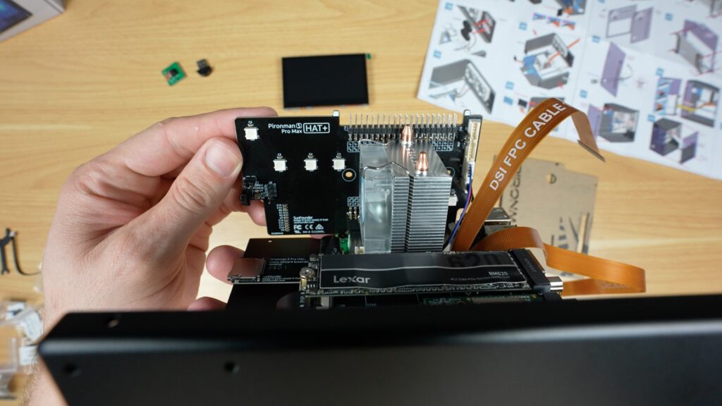
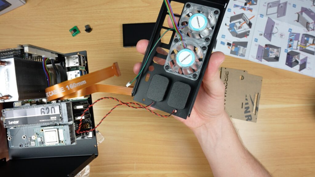
The RGB, display and GPIO adaptor plugs into the Pi’s GPIO pins. Next, two fans go onto the back panel with some screws, and two speakers are stuck on underneath them.
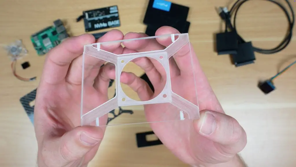
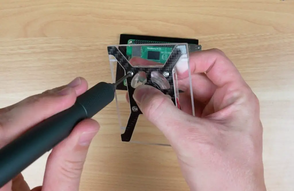
The camera cable is the same design as it is in the Max case, but this time they include a camera and the adjustable mount. The OLED stats display on the front is also the same.
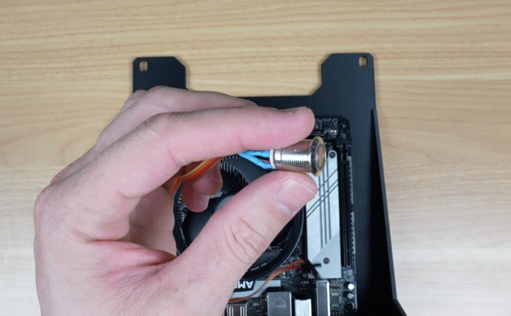
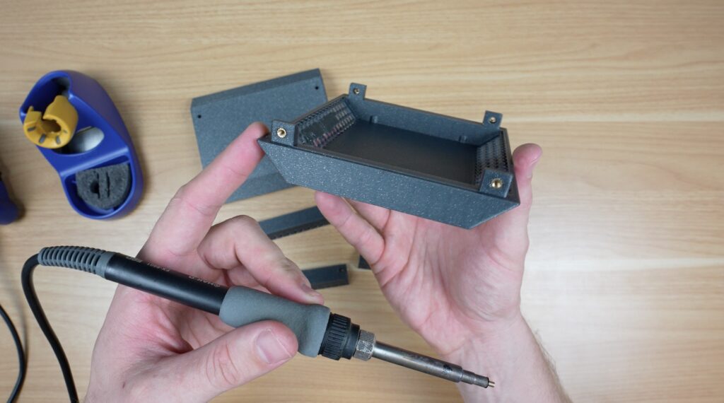
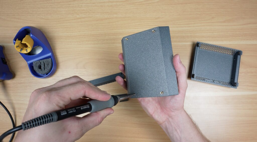
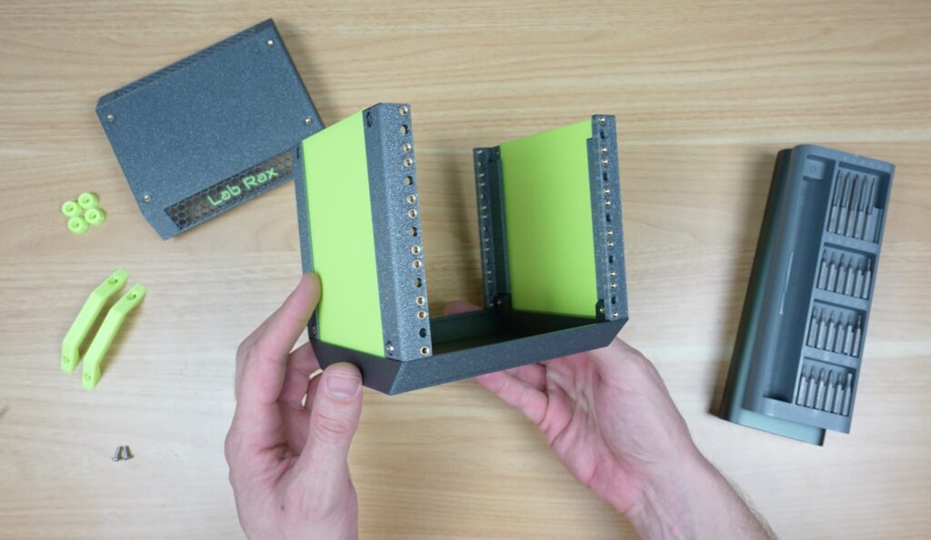
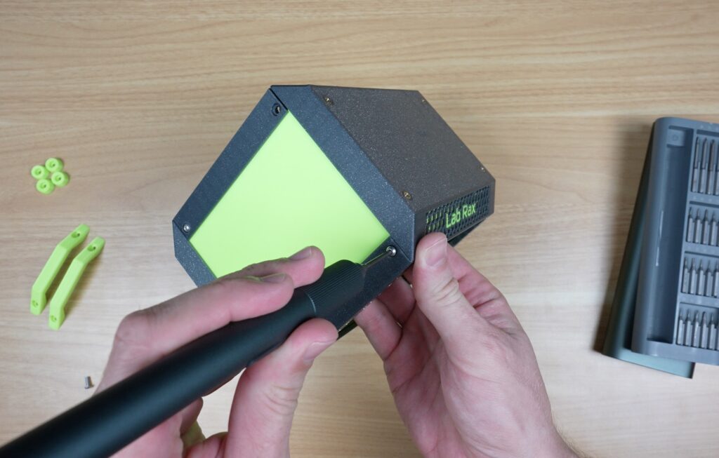
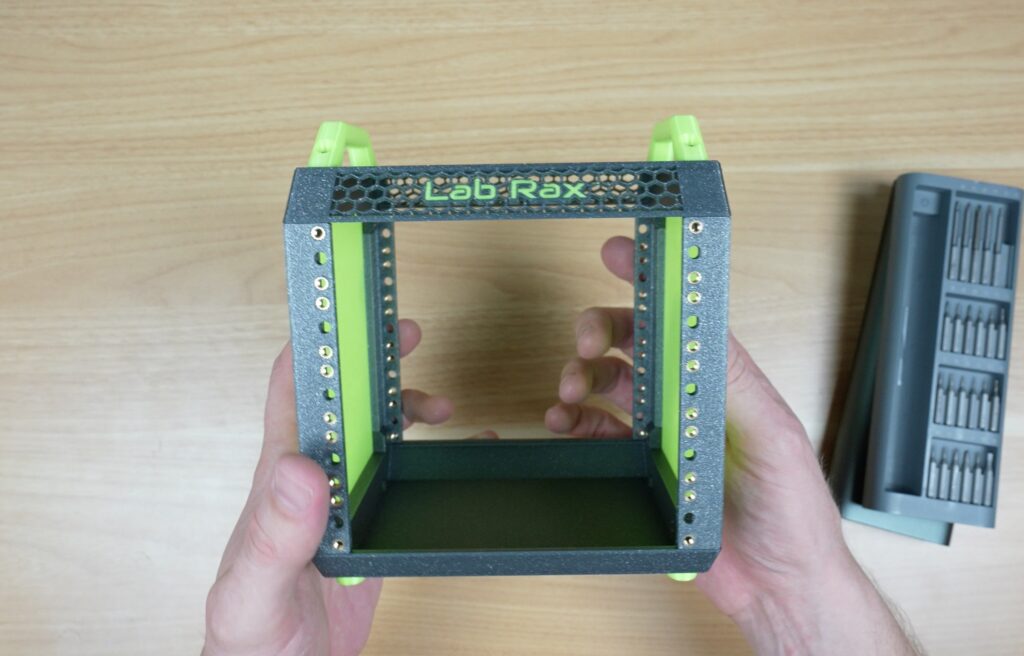
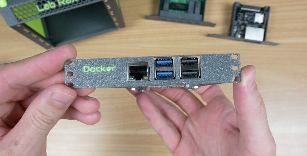
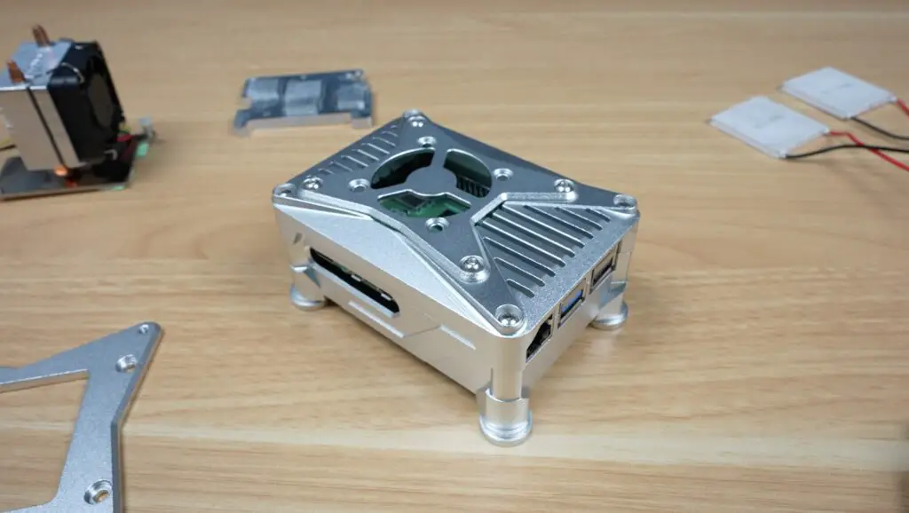
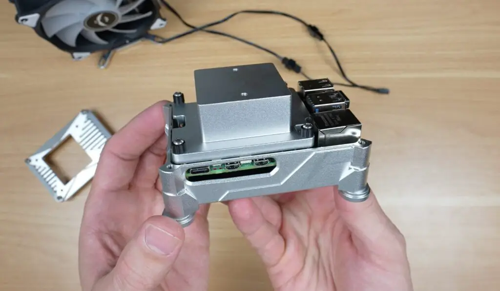
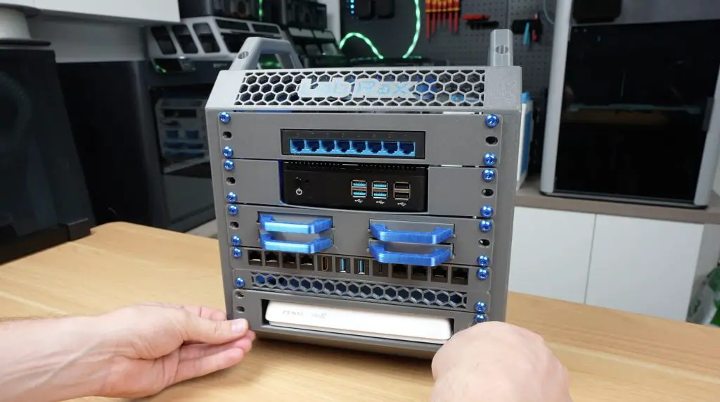
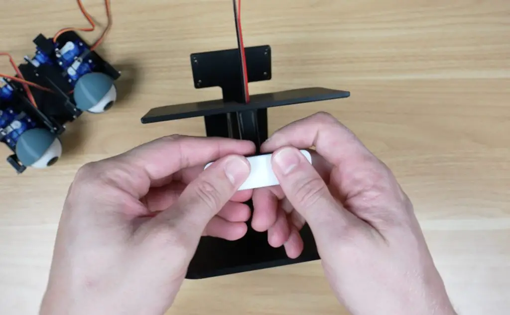
With those all installed, we can start closing up the case, firstly by screwing the two aluminium case halves together. The acrylic front panel gets the power switch installed on it and can then be screwed into place.
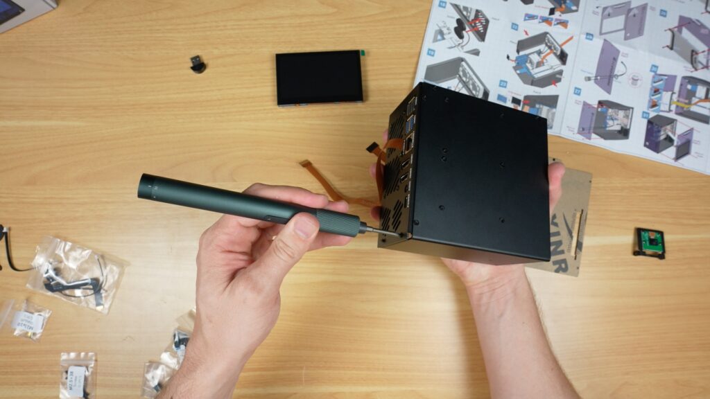
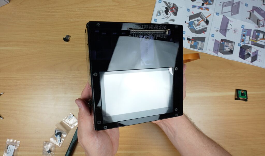
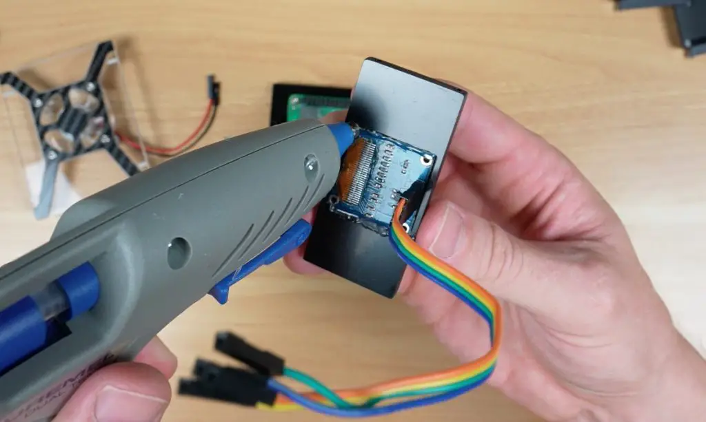
And the display then gets mounted onto the acrylic side panel. It then plugs into the Pi, and we can then close the case up.
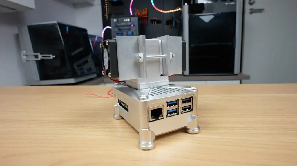
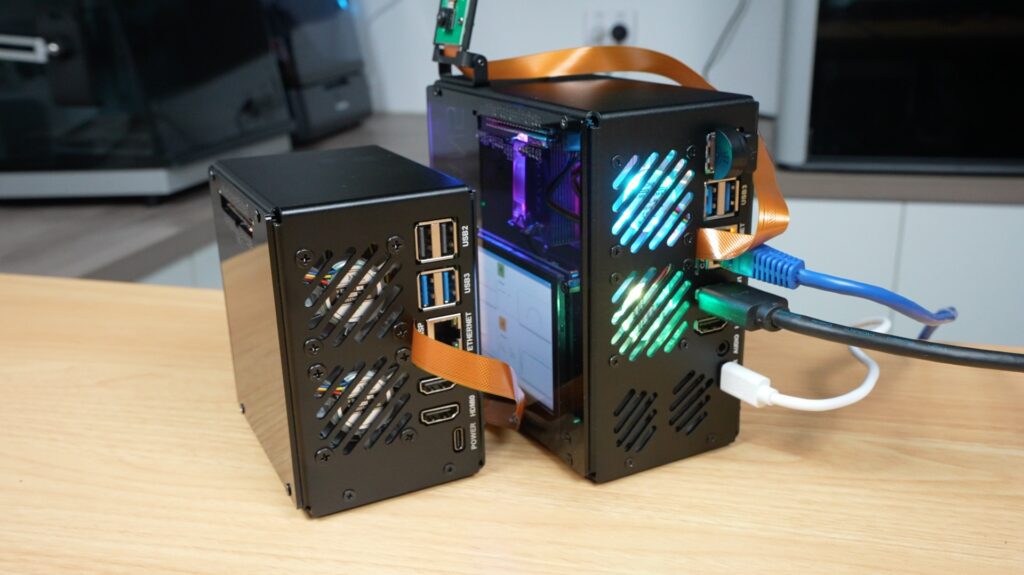
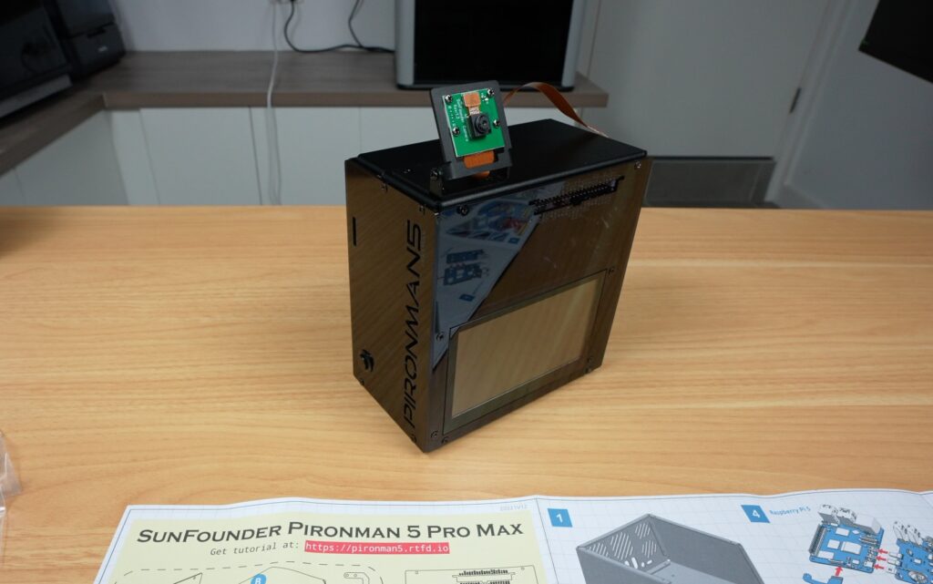
To finish it off, there are some rubber feet for the bottom of the case, the USB microphone plugs into one of the USB 2 ports on the back, and the camera gets mounted on top of the case.
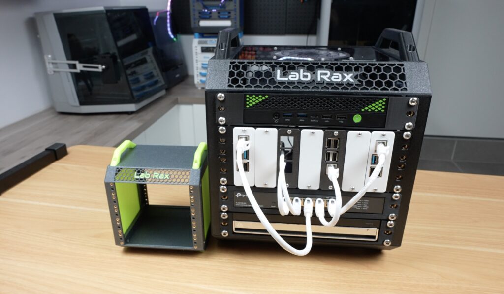
And that’s the case assembly complete. All up, this took me about 45 minutes to assemble, and that’s while recording it too. So, like with Sunfounders’ other cases I’ve put together, this one is fairly easy to assemble and has a well-guided process.
Like with their other cases, they also give you some extra screws and hardware in case you lose or break any of them.
First Boot and Software Installation
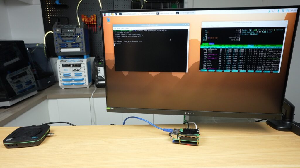
Next, we need to boot it up and install the software to use some of the included accessories.
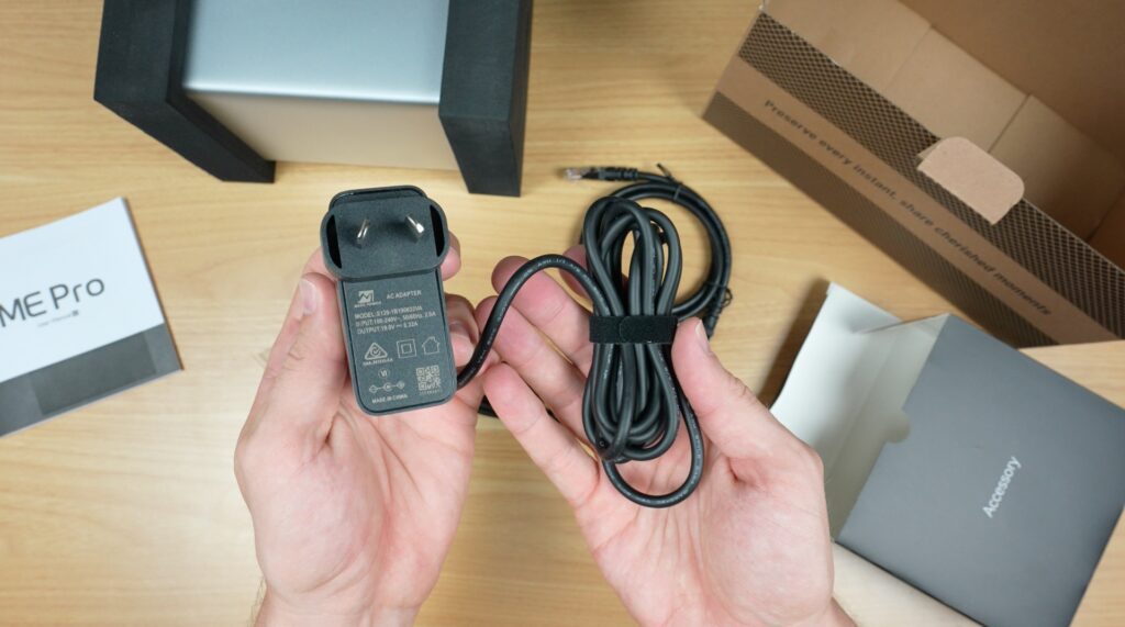
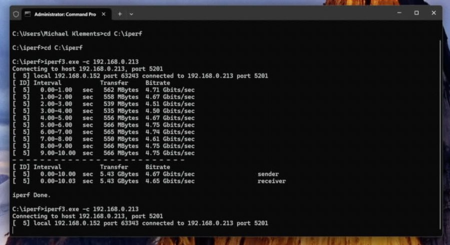
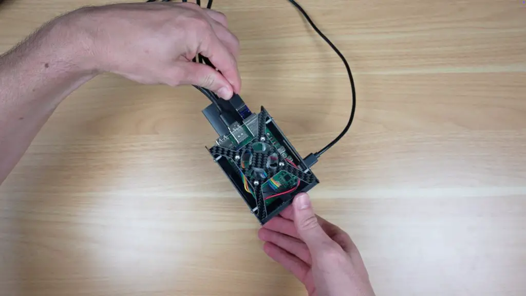
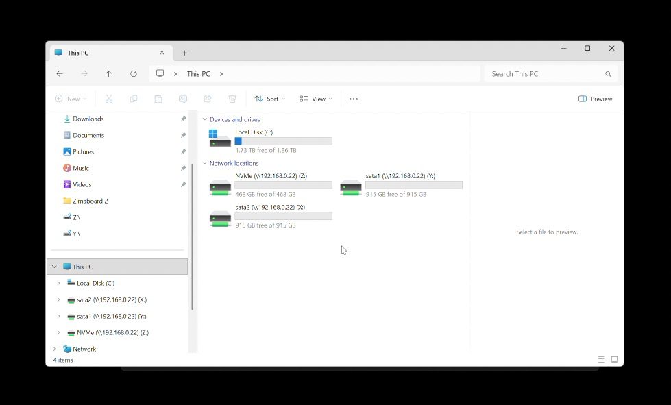
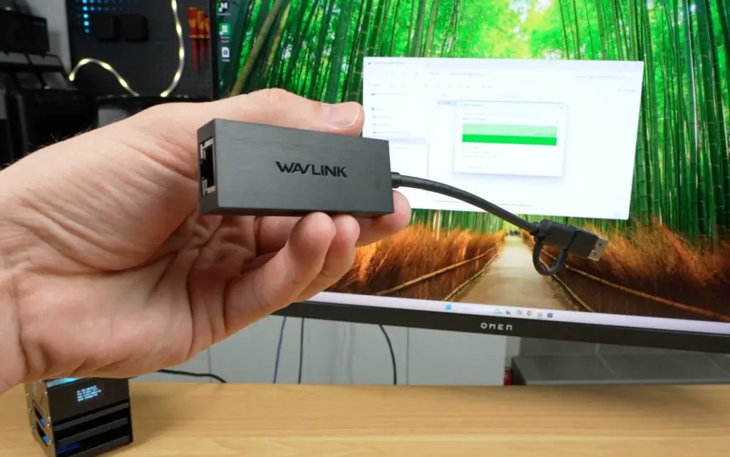
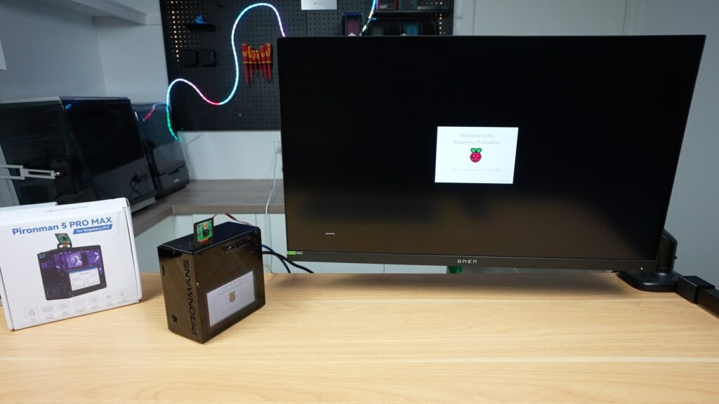
I’ve preinstalled Raspberry Pi OS onto the NVMe drive, so we just need to plug in some cables for the power supply, network and monitor, and it’s ready to go. I plugged it into my monitor because I wasn’t sure if the display would work straight away, but it was recognised, and it even came up as the default display. So technically, you could set this up with just a power cable being plugged in.
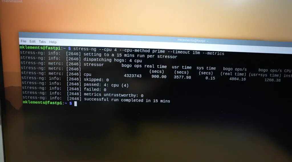
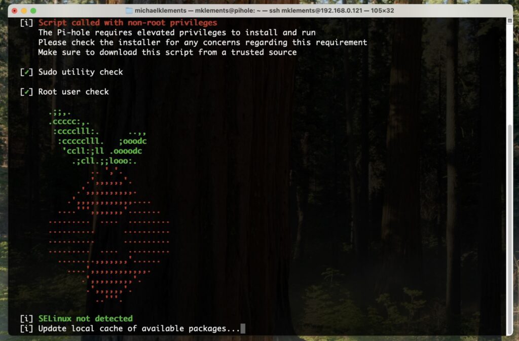
The OLED display and internal RGB lighting, however, need the software to be installed. This is easy to do by following their Wiki and just requires a single-line command to run in the terminal, which requires a reboot at the end.
cd ~
git clone -b pro-max https://github.com/sunfounder/pironman5.git --depth 1
cd ~/pironman5
sudo python3 install.py
After the reboot, the case comes to life.
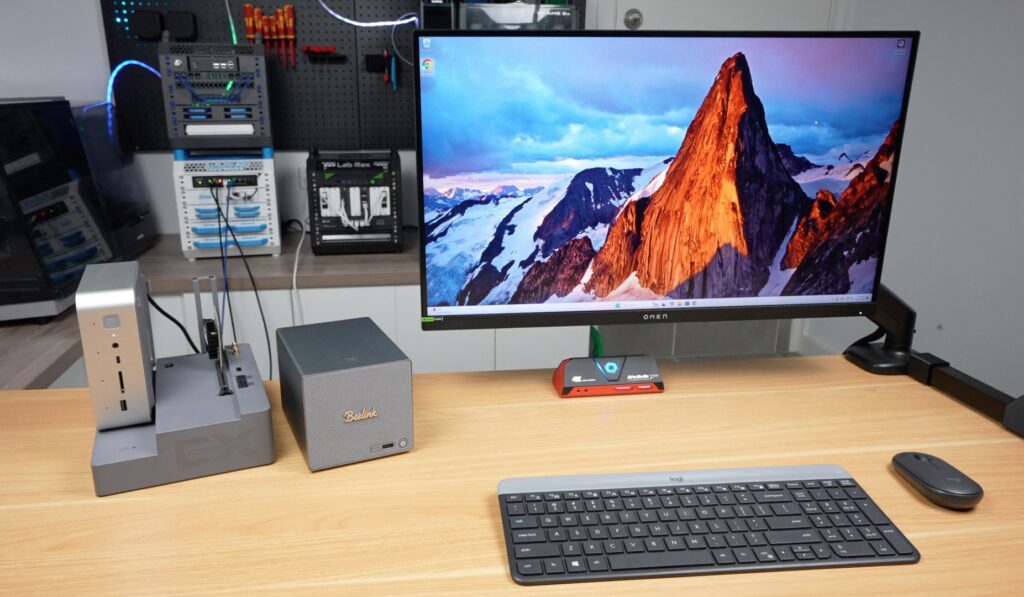
Pironman 5 Pro Max Features and Inclusions
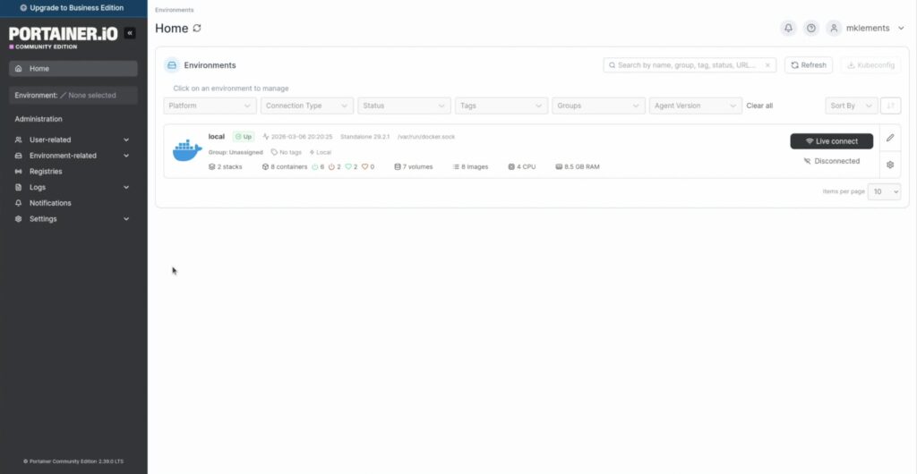
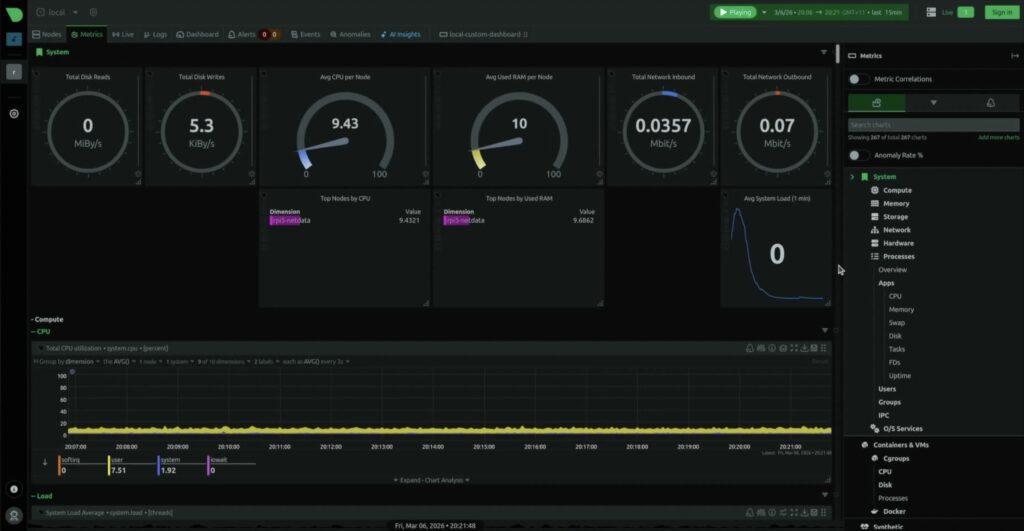
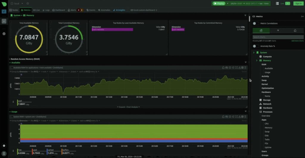
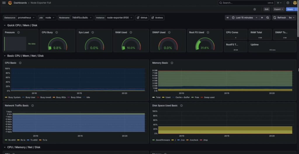
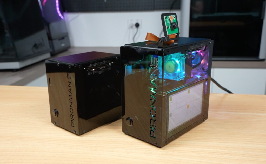
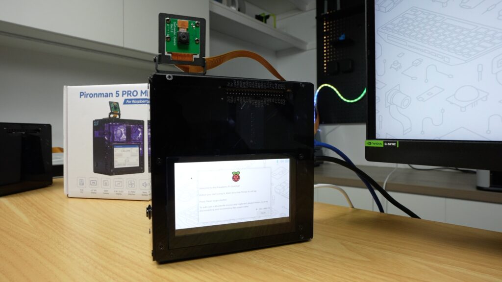
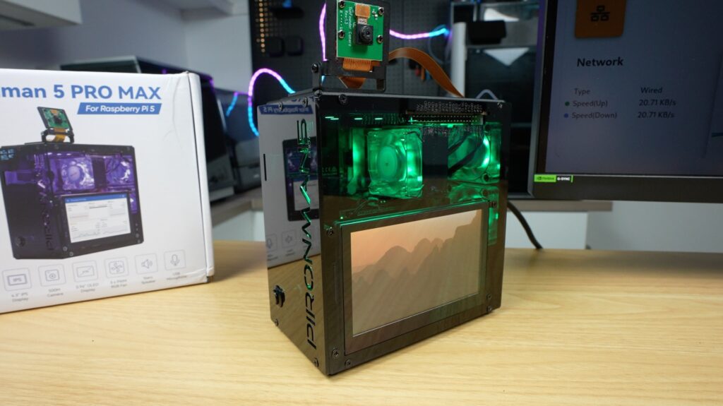
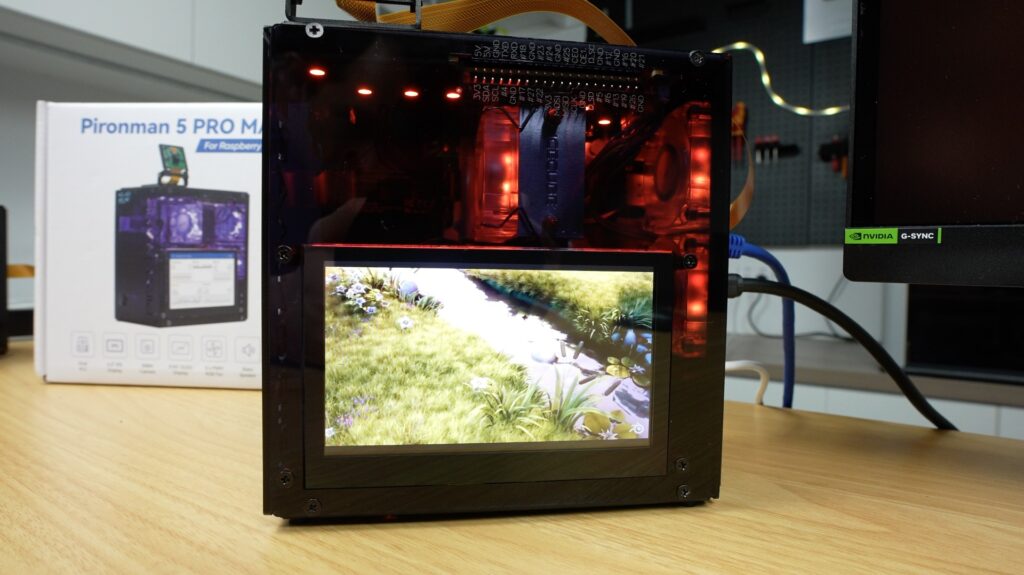
The most noticeable addition is definitely the touchscreen. Instead of just showing simple stats like the OLED display, this gives you a full interface that you can use to display system info, run dashboards, or build custom interfaces for.
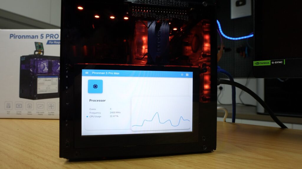
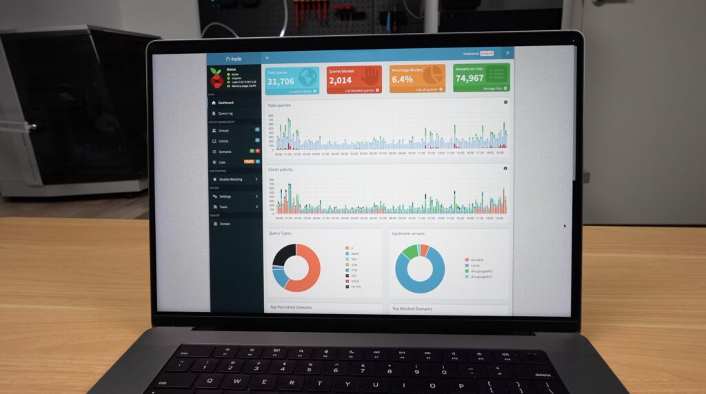
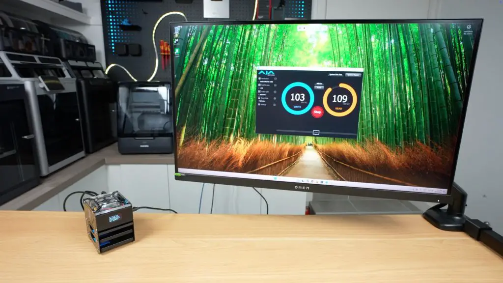
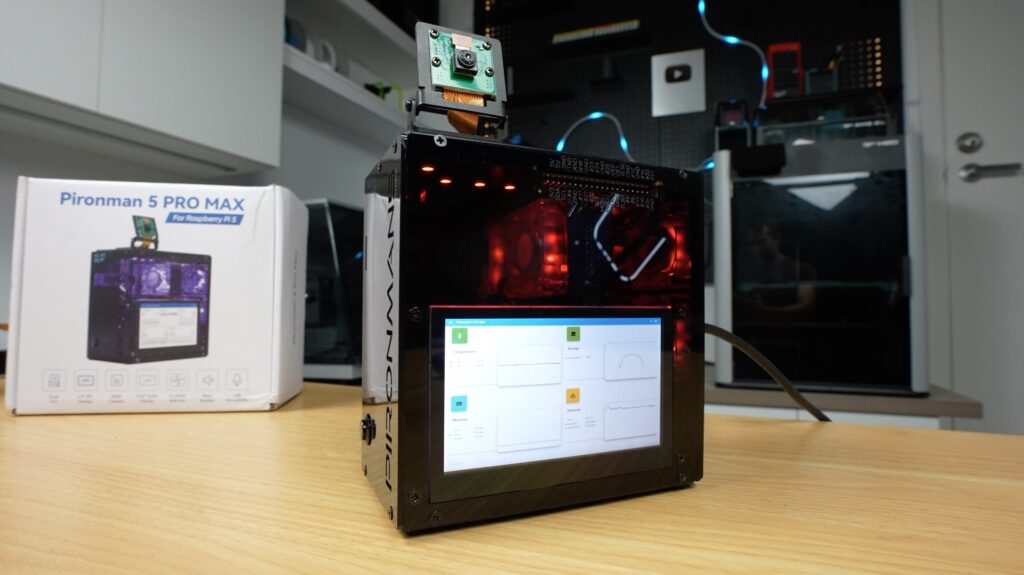
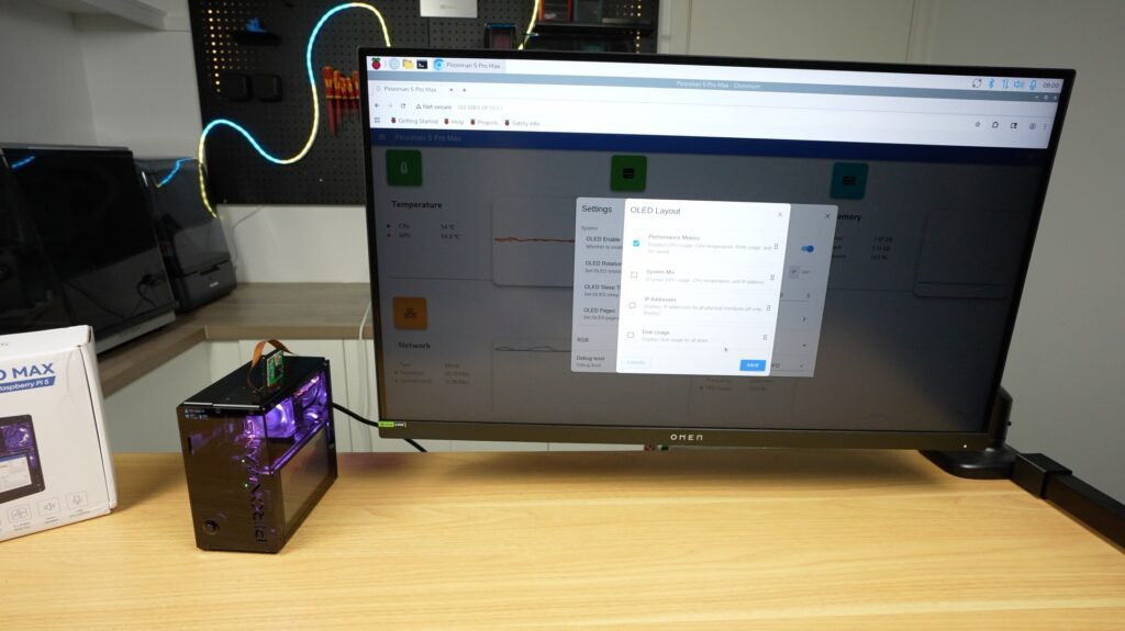
Their Pironman dashboard, which is installed as part of the script, includes a nice monitoring page that can be displayed on your main monitor or full screen on the cases display. You can access this dashboard by going to your Pi’s IP address and port 34001 in the browser:
http://<ip>:34001This display makes this setup far more usable as a standalone device rather than something you need an external monitor for or need to SSH into.
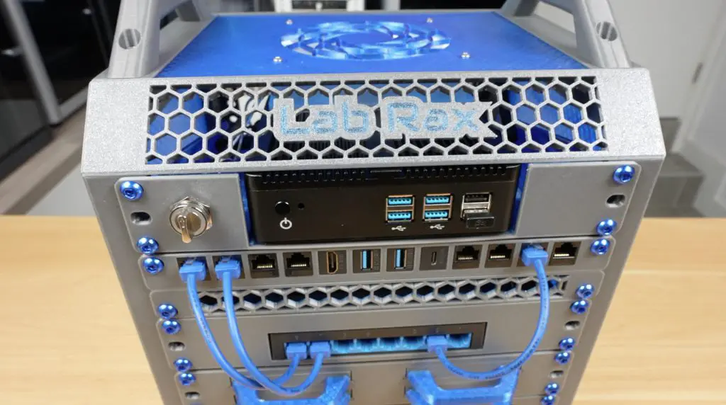
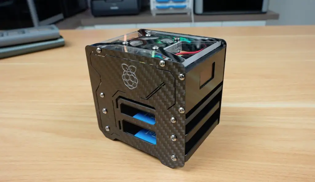
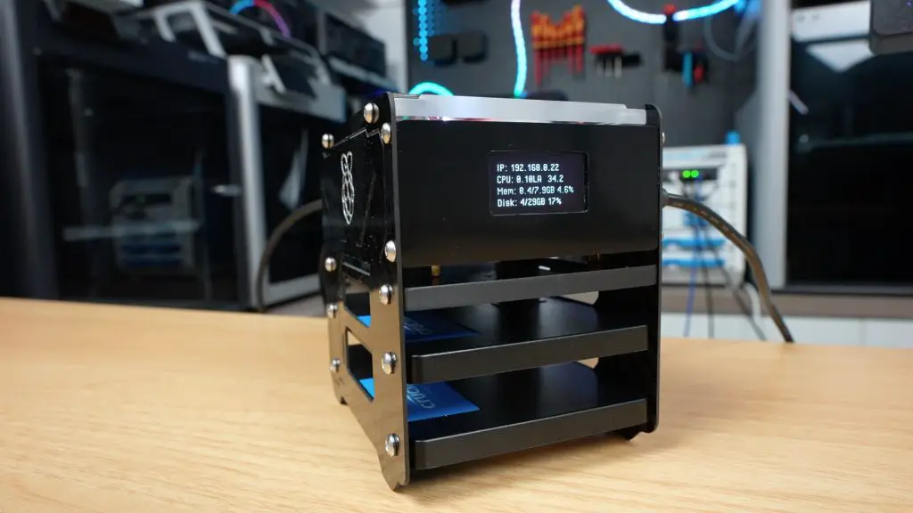
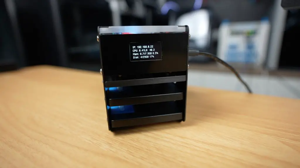
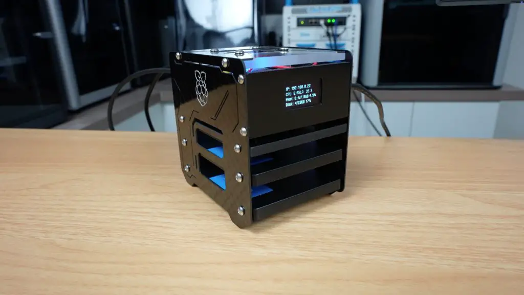
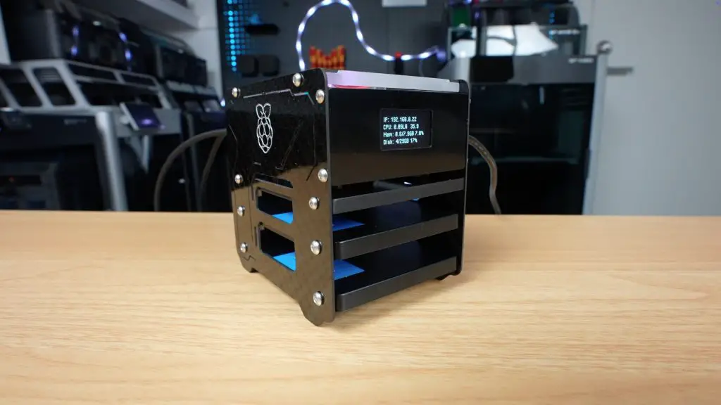
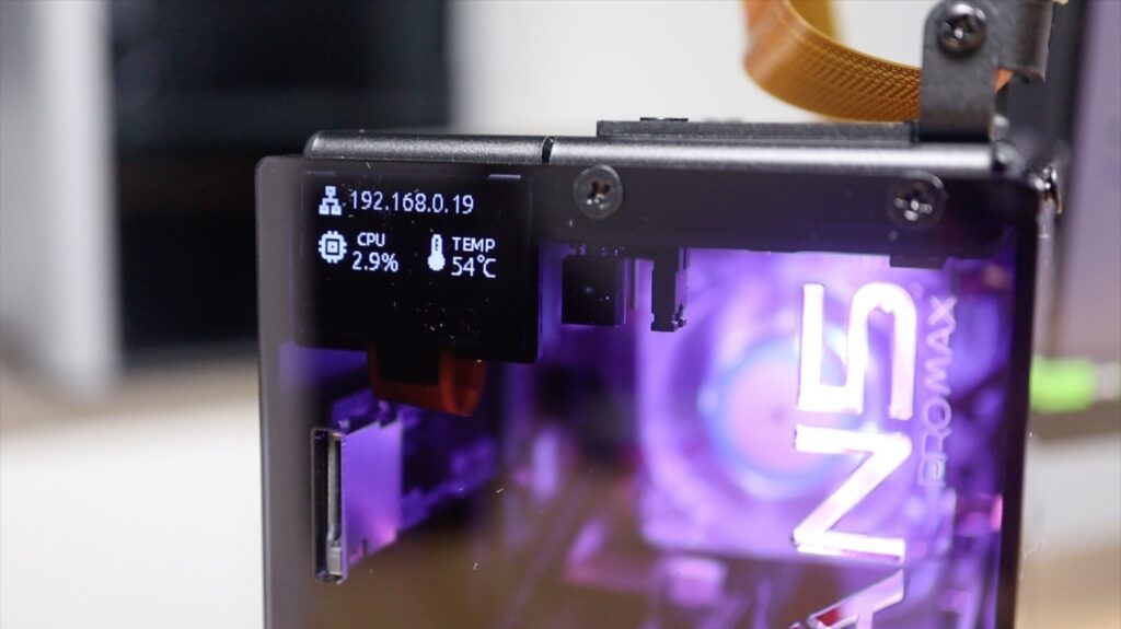
It’s also still got the OLED stats display in the front, which, like the other Pironman cases, can be set up to display a couple of different metrics or cycle through them.
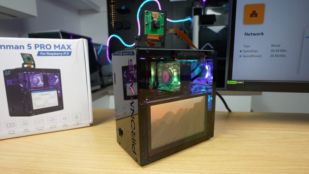
The integrated RGB lighting is also controllable with a number of options. It’s really cool that they’ve synced the fans up with the LEDs at the top so they’re all working together.
Next up is the audio. The built-in speakers are ok for their size. I get why they’ve gone with two so that stereo audio plays back correctly, but with the space limitations, they would have gotten much better audio quality out of a single larger speaker.
That said, they’re ok for system sounds, basic voice output or light media playback. You’re not going to want to watch a movie on here, but that’s not really what it’s made for anyway.
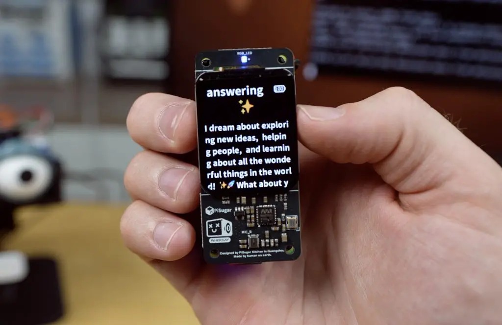
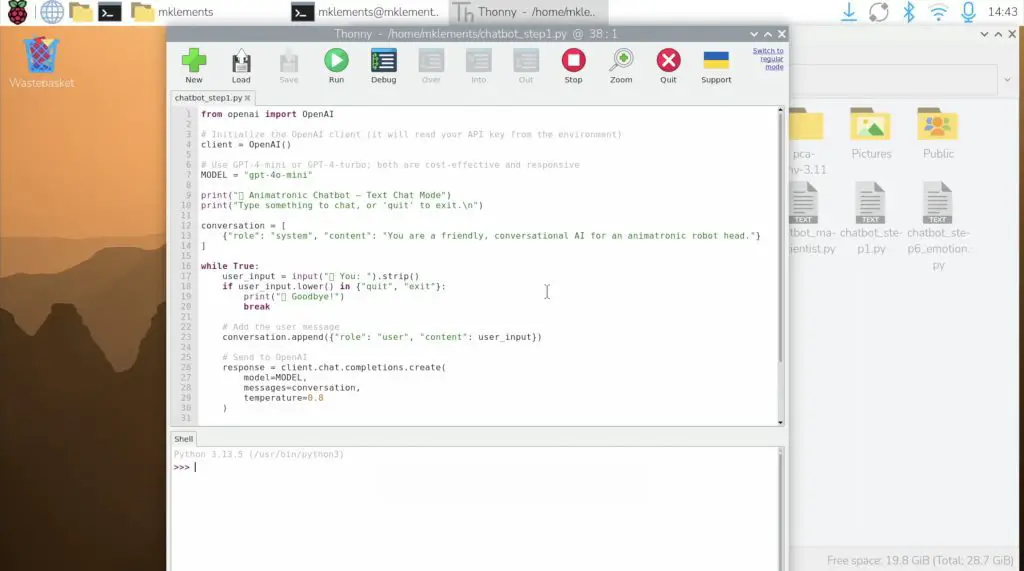
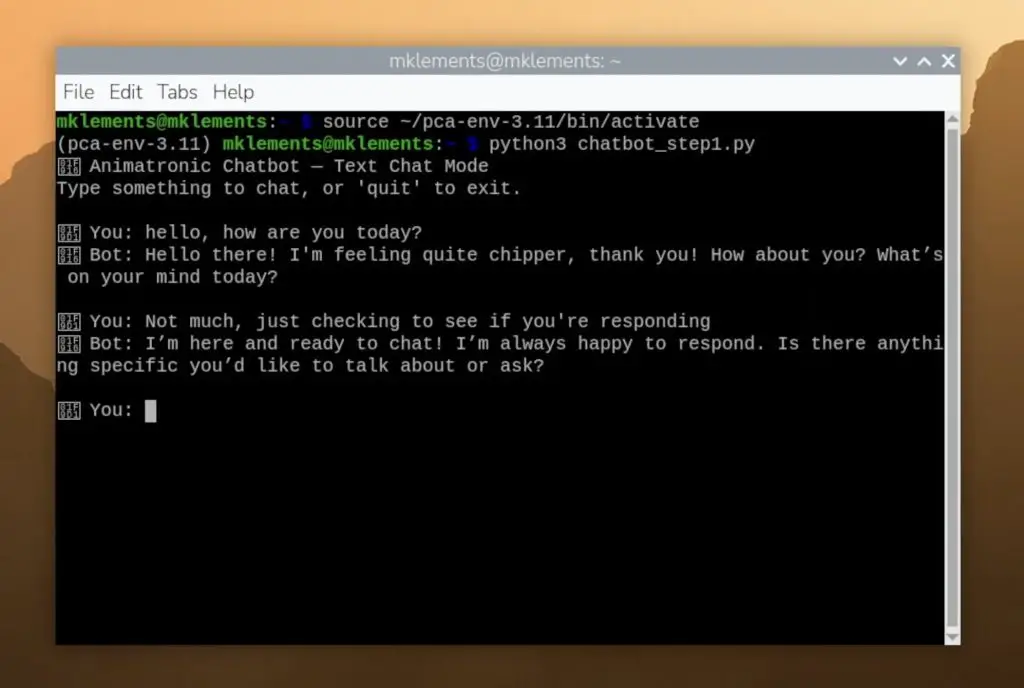
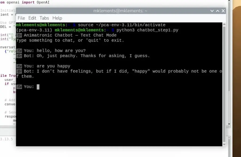
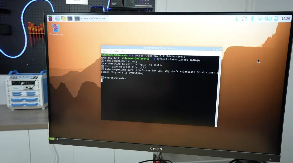
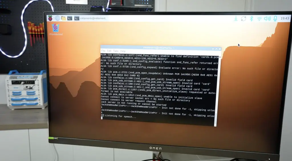
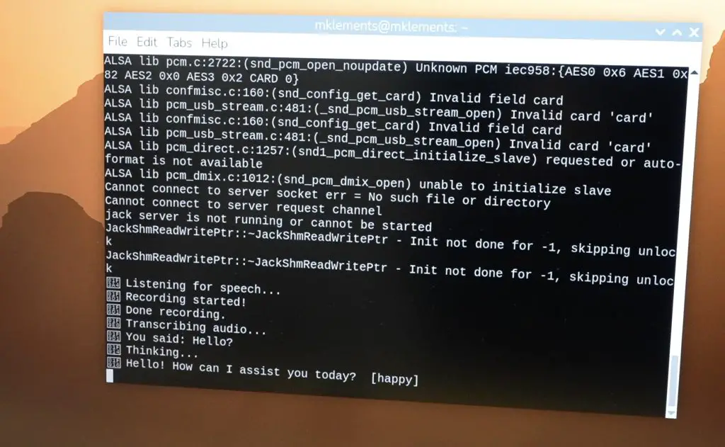
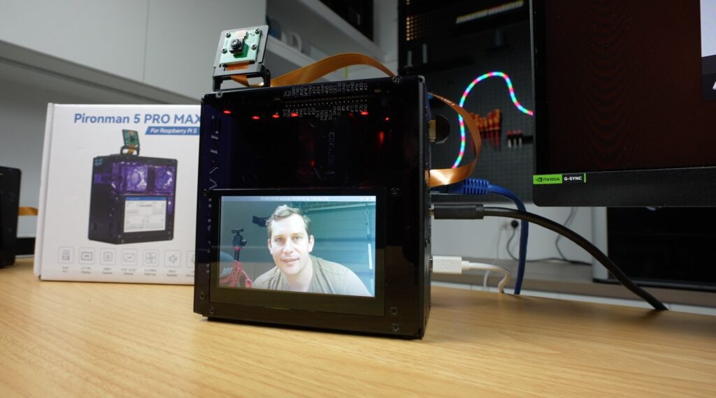
The microphone works straight out of the box and is detected as a USB device. This is useful for voice assistants, like the one I built a few months ago.
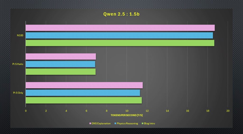
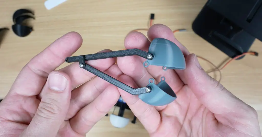
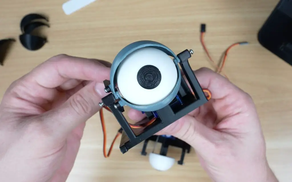
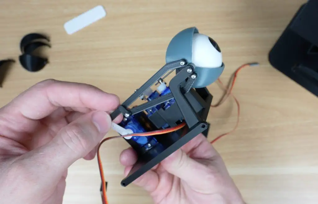
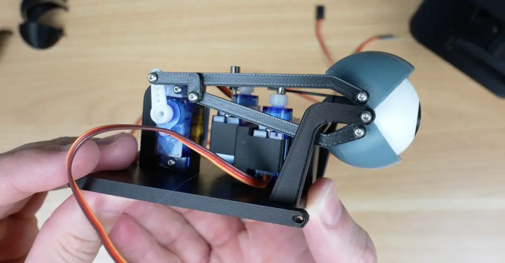
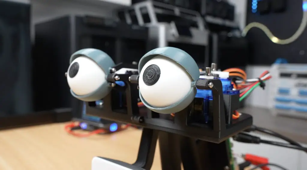
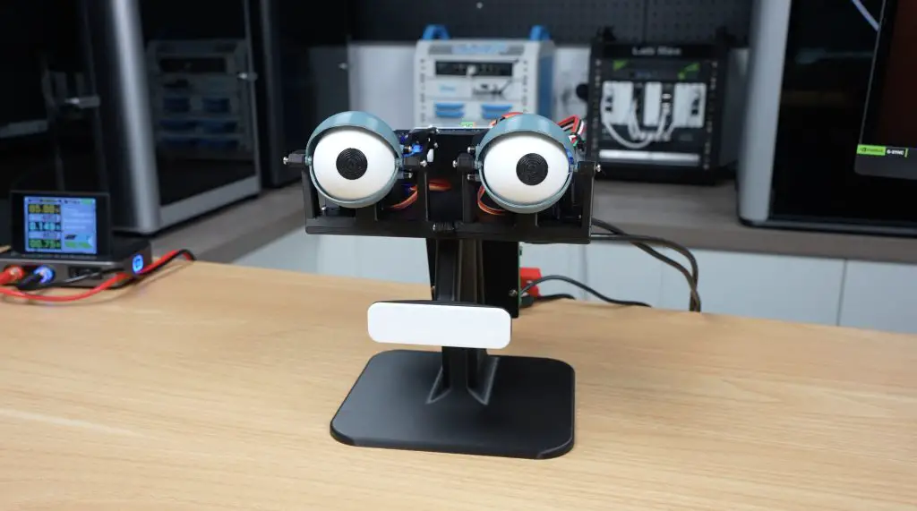
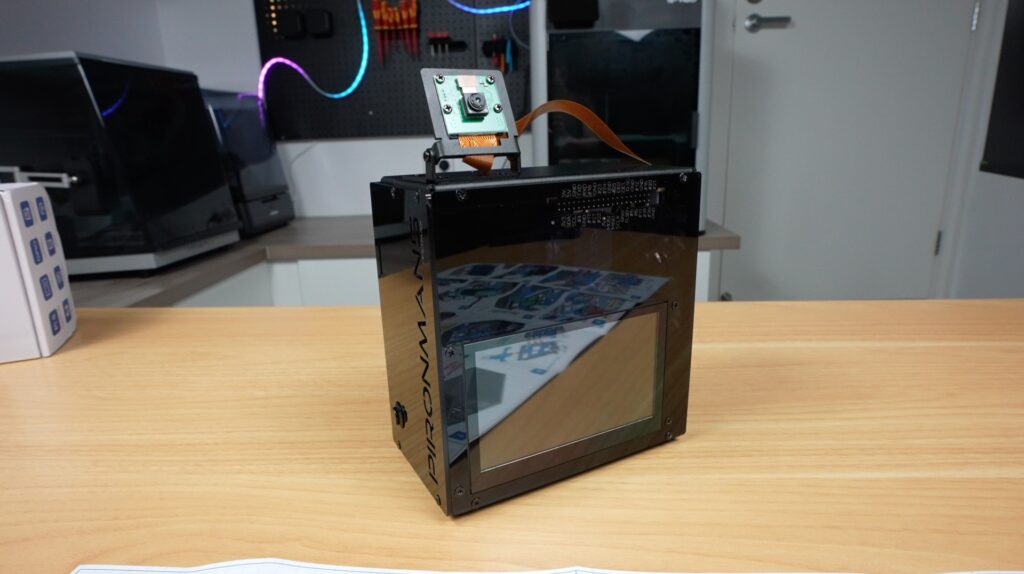
Lastly, let’s look at the camera. With the built-in mount, it’s easy to position it to focus on your target. This addition fits in with the theme of the other inclusions, allowing for face tracking, object detection, or general vision-based AI projects. And you can use the accelerator in the second M.2 slot to help out with these.
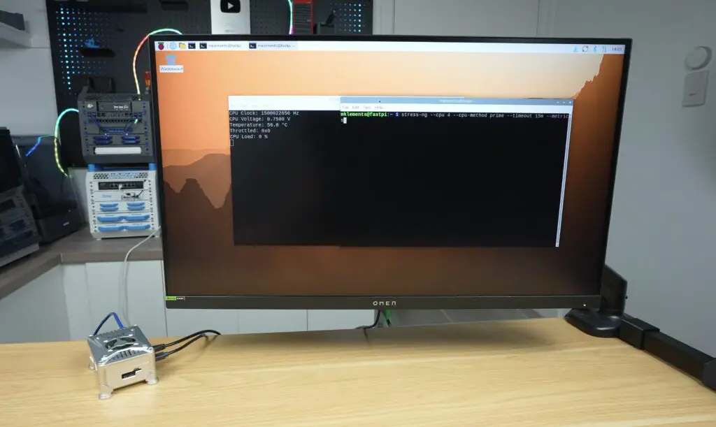
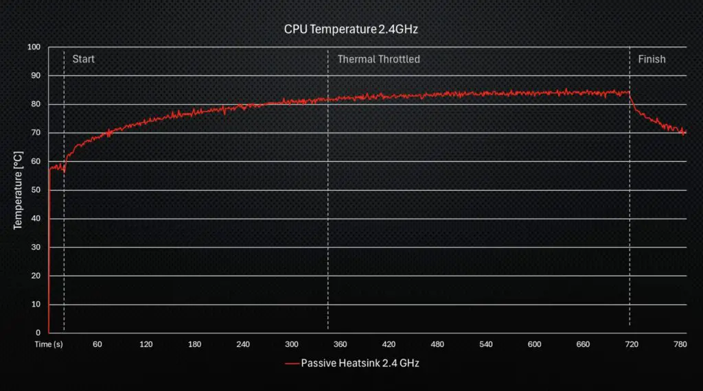
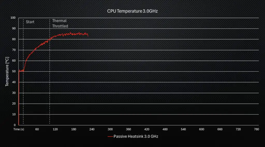
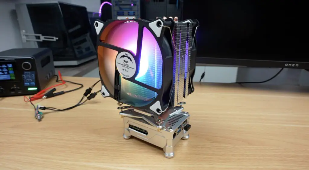
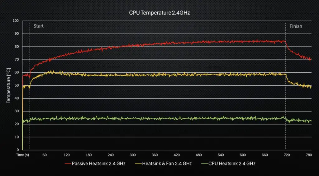
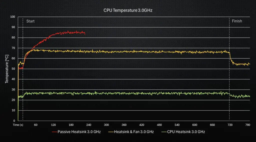
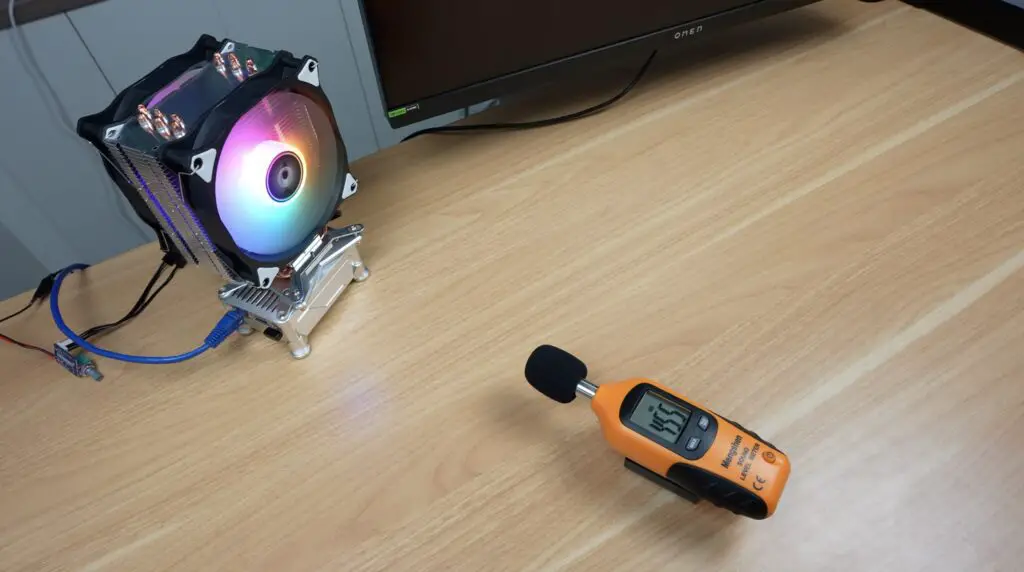
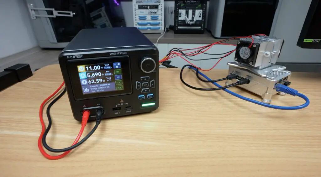
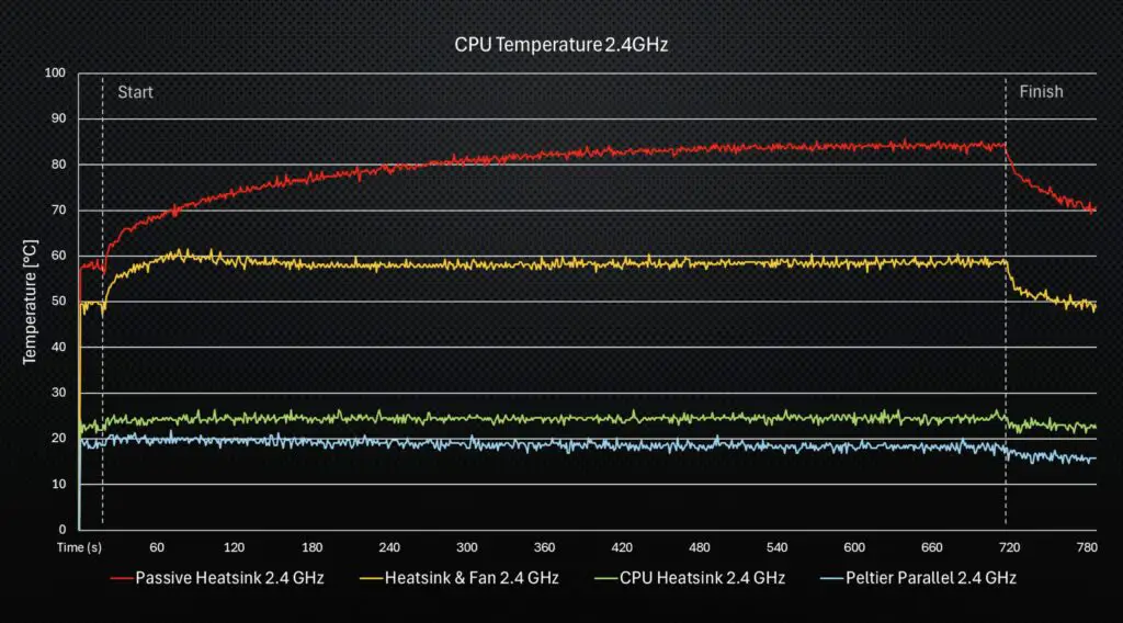
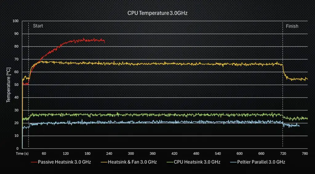
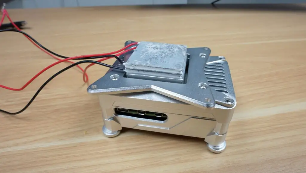
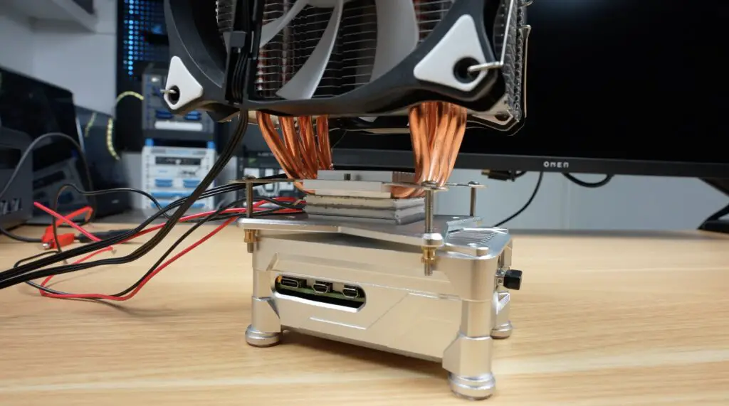
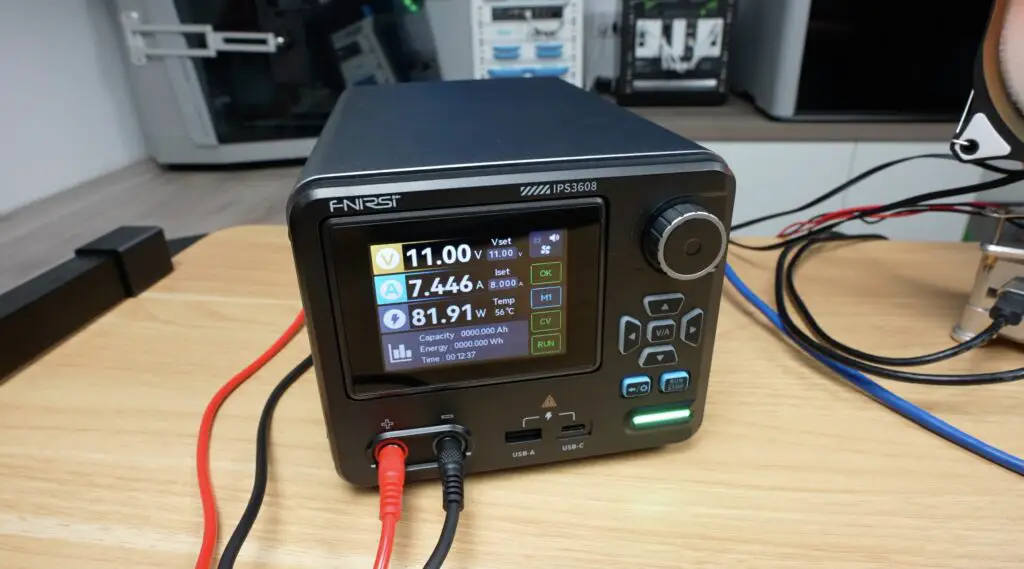
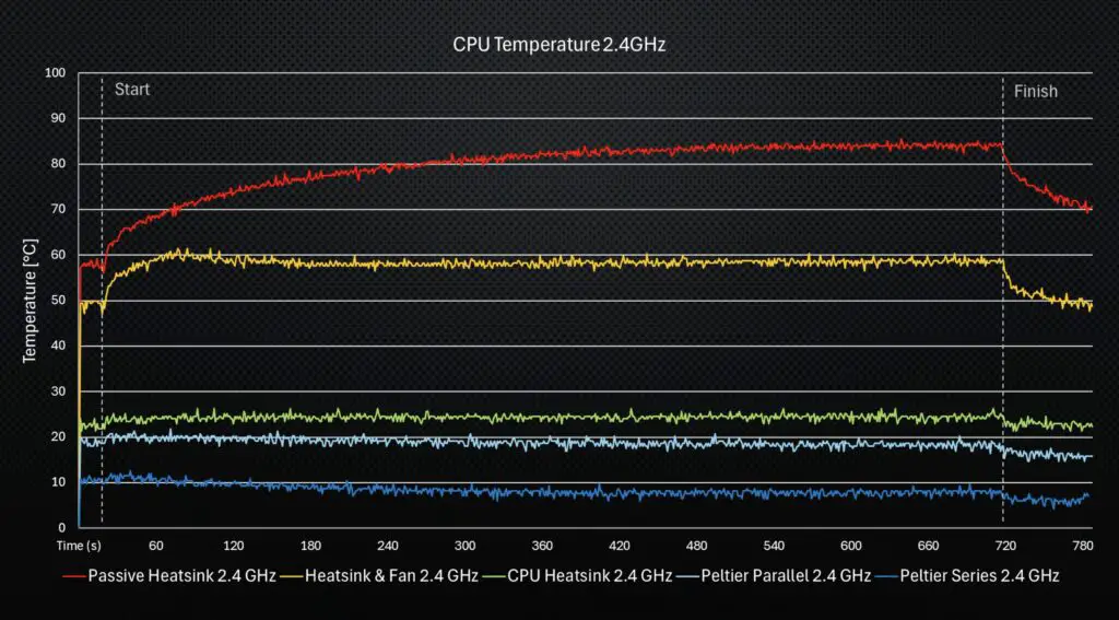
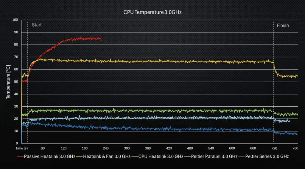
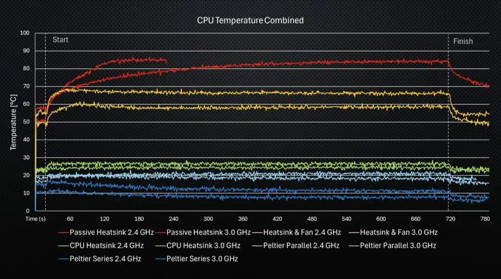
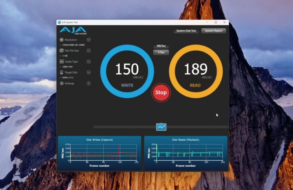
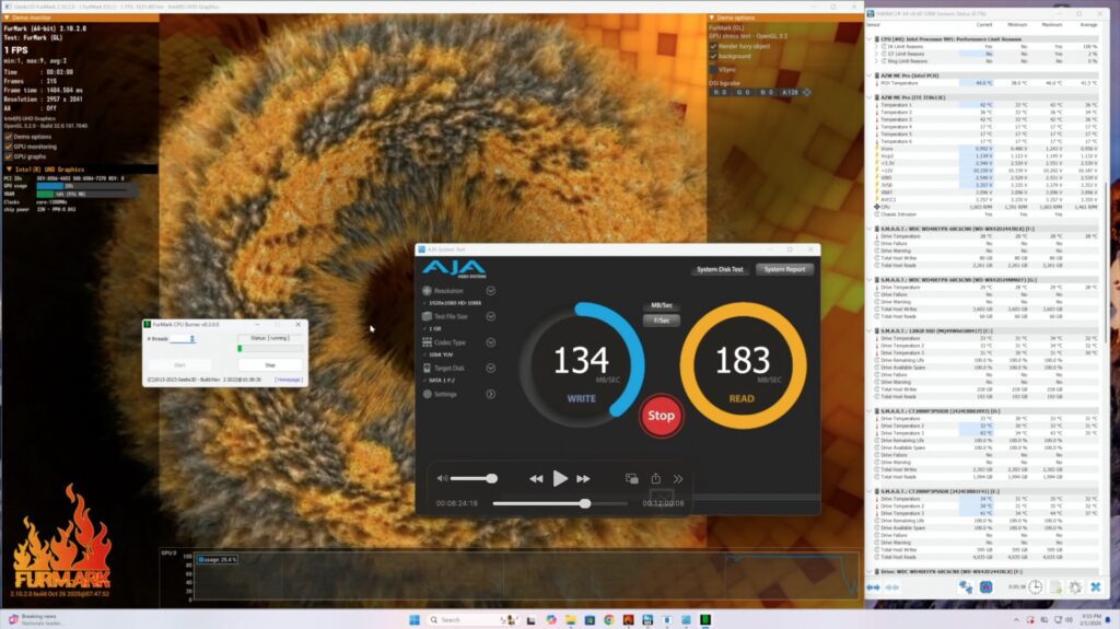
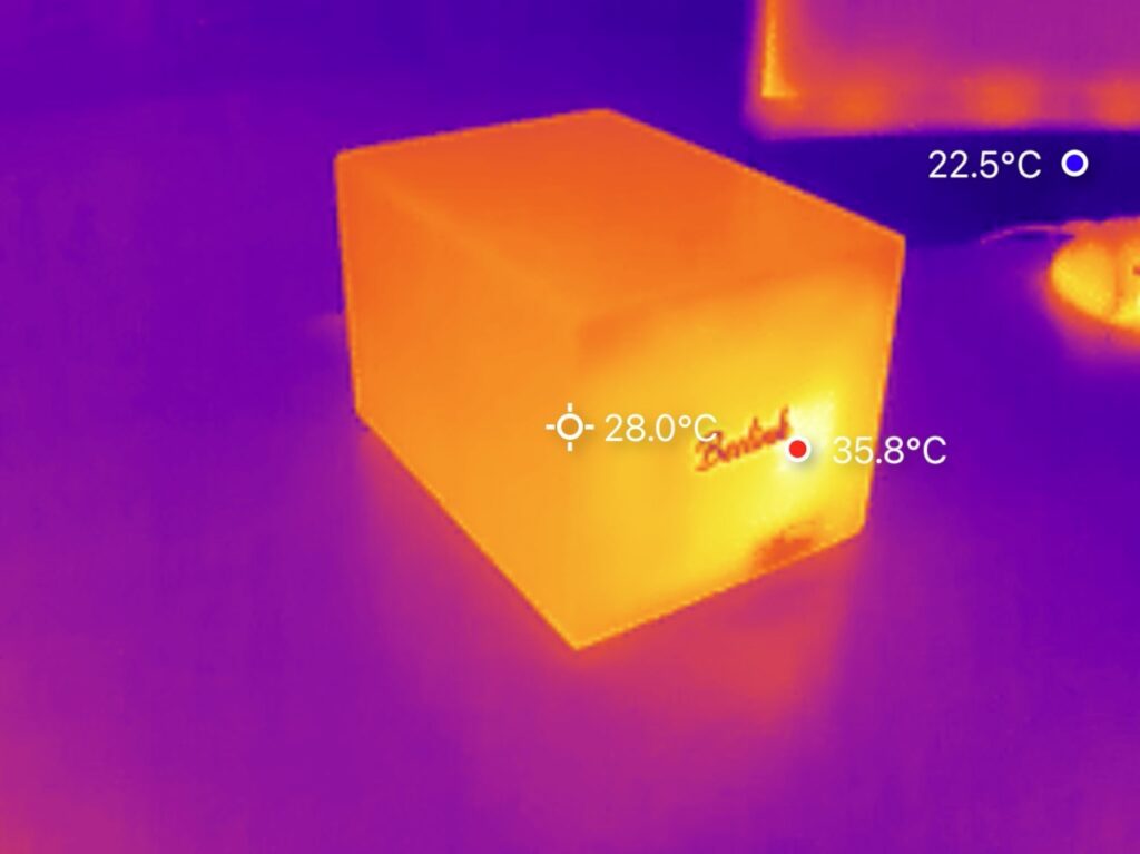
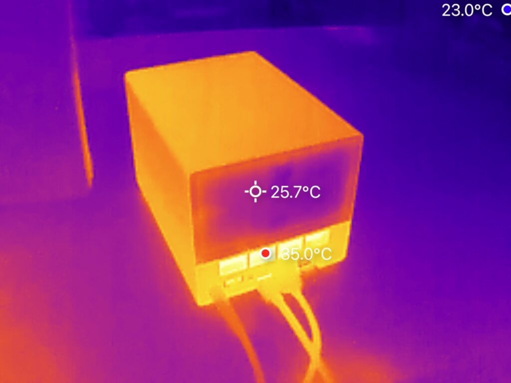
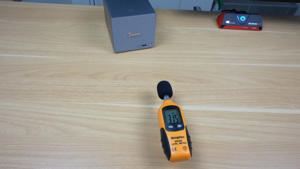
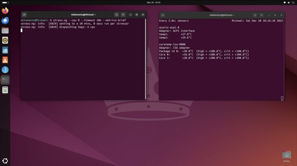
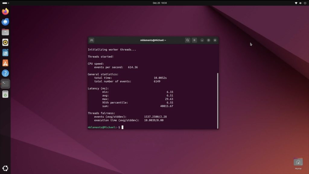
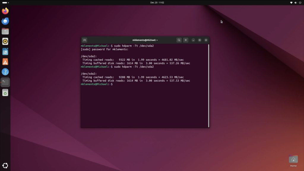
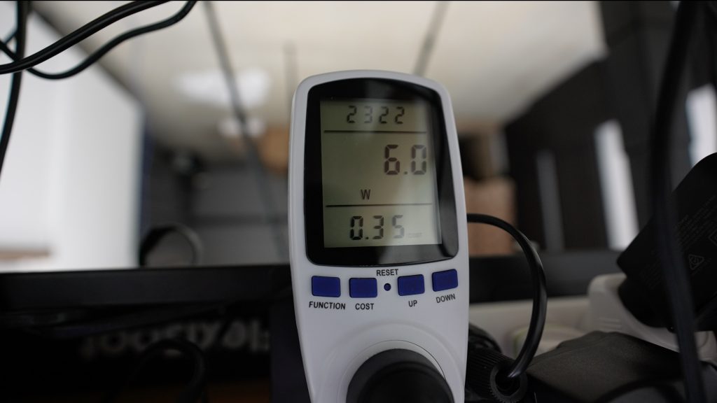
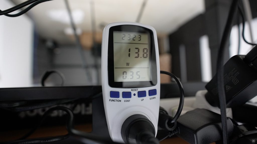
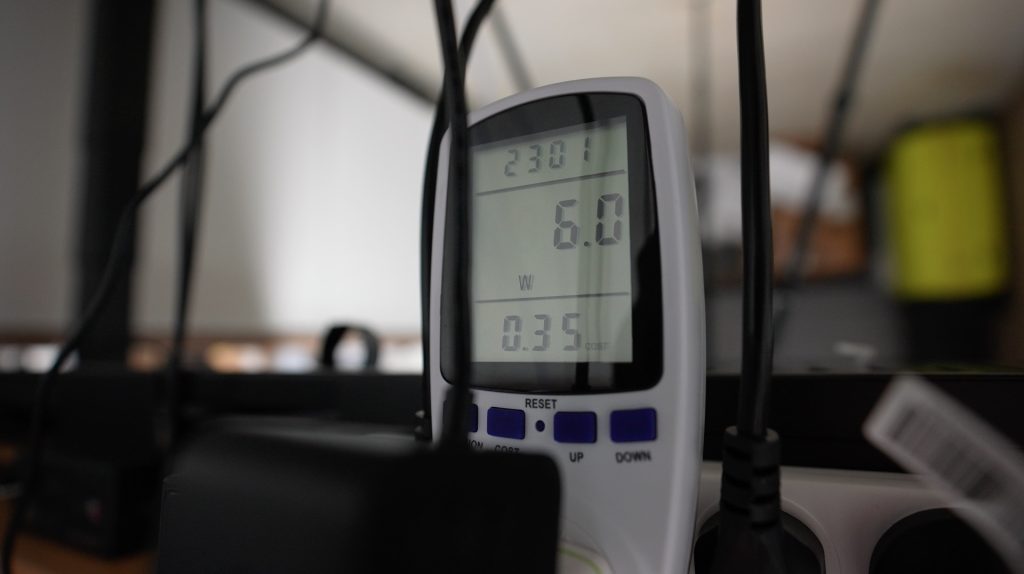
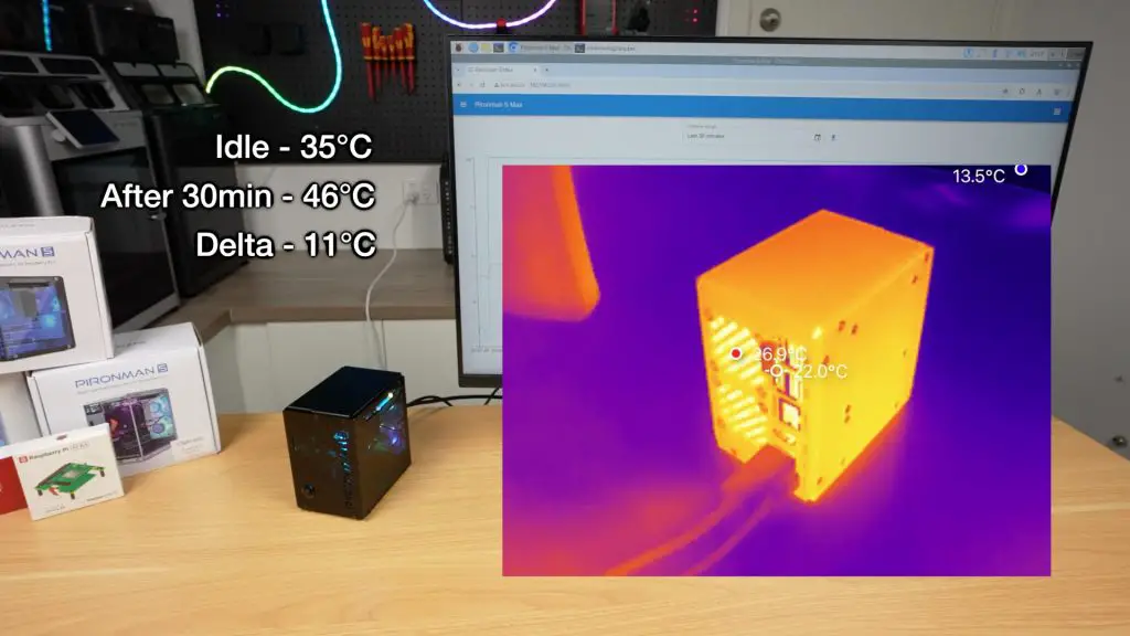
Thermal and Noise Testing
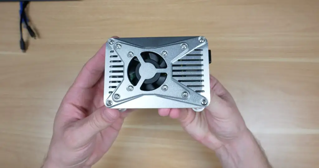
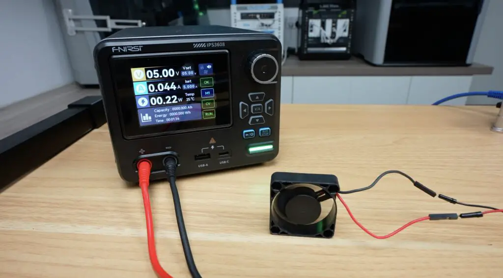
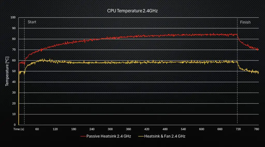
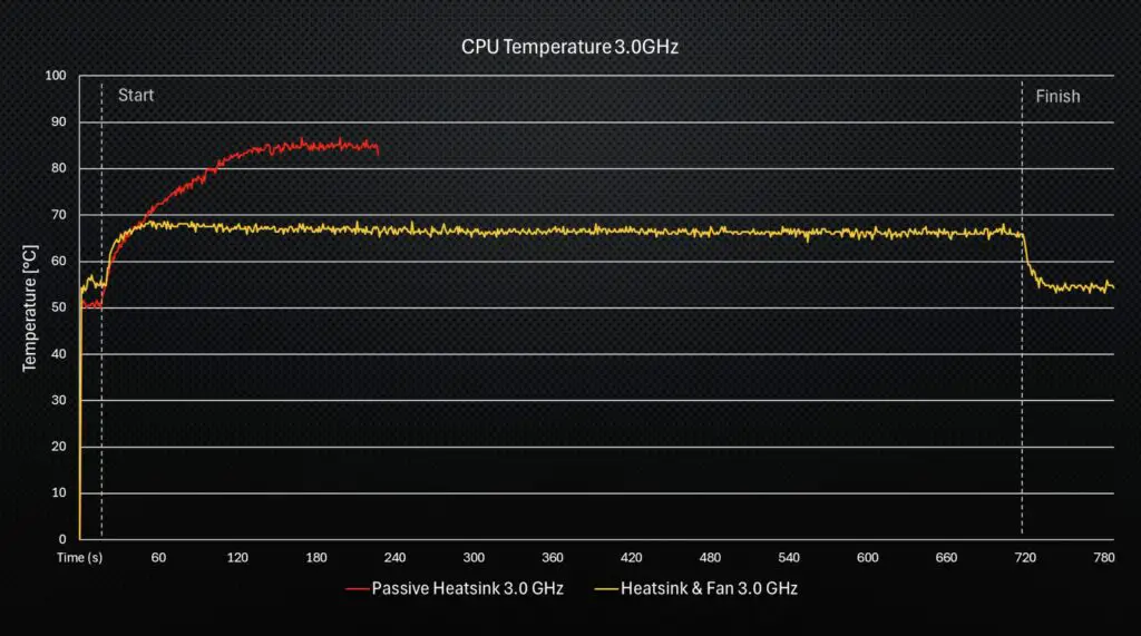
I’ve already thoroughly tested the thermals and fan noise levels on the Pironman 5 Max case, and while this case does have a few new features, the cooling system and fan choices are unchanged. Both have the same tower CPU cooler with 40mm fan and dual 40mm fans on the rear, so I expect the results will be comparable.
Thoughts on the Pironman 5 Pro Max & the Pironman 5 Lineup
So, having tried both the Pironman 5 Max and this Pironman 5 Pro Max, I’d say that the Max is designed to be a high-end Pi case, which is great for servers, NAS builds, or desktops, while the Pro Max is better suited for AI applications, dashboards, and smart systems, or projects requiring human interaction with the device.
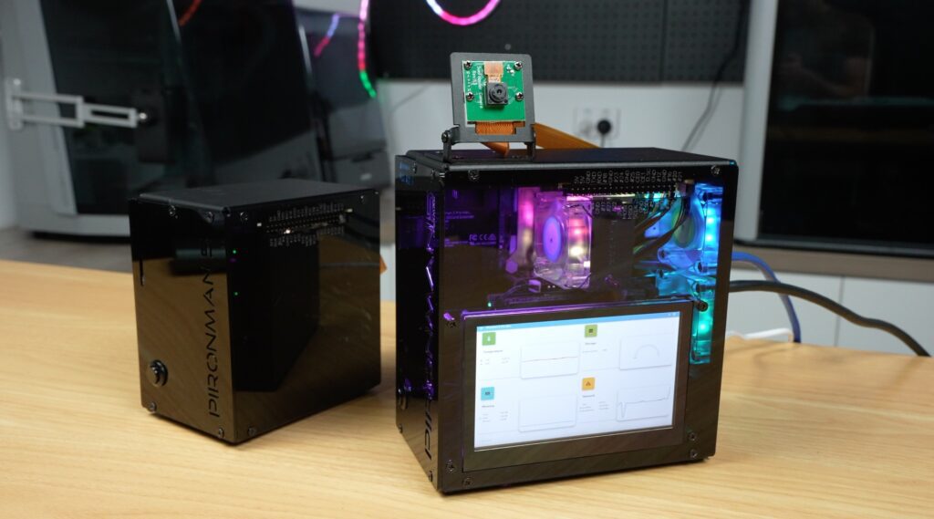
The Pironman 5 Pro Max basically turns your Pi into something closer to a smart assistant, kiosk or an edge AI workstation.
It’s an interesting addition to the Pironman lineup. I don’t think it replaces the Max, but rather changes its purpose. I do wish they got a bit more creative with the naming scheme, though. We’ve got the Pironman 5, Pironman 5 Max and now the Pironman 5 Pro Max – which I think serve different functions rather than just to be better versions than their predecessor, as the name suggests.
As with the other cases in this line, though, it’s no longer just a small computer that you hide away. It’s something you actually want to look at and interact with directly.
The only thing I don’t really like is the cable management to the camera. It looks a bit messy and a bit like an afterthought. They could rather have fed the ribbon cable through to the camera internally with just a short exposed section underneath the camera.
Let me know what you think of the Pironman 5 Pro Max case. Is this something you’d actually use, or is it a bit overkill?
At $146, it is quite an expensive case for a Raspberry Pi, but when you consider that this case turns the Pi into a full standalone workstation that includes quite literally almost every accessory you might need to add on, it’s not terrible value. Especially given that it’s assembled into a really good-looking package.
Let me know what you think of the Pironman 5 Pro Max or their other Pironman series cases in the comments section below.