Building a Raspberry Pi cluster usually means dealing with messy cables, stacks of boards, and a tangle of power supplies. But what if you could shrink all of that into a single, compact board?
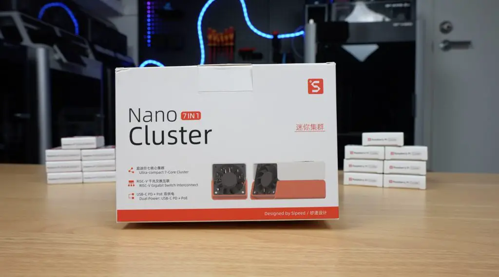
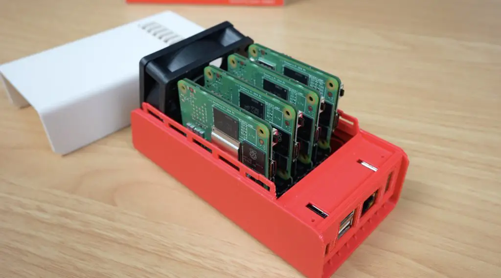
That’s exactly what the Sipeed Nanocluster does. It’s a small board and enclosure that lets you run multiple Raspberry Pi Compute Modules together as a compact cluster computer, and it literally fits in the palm of your hand.
Here’s my video review of the Sipeed Nanocluster, read on for the write-up;
The Sipeed Nanocluster is still in development, but you can preorder it from Sipeed’s website. Pricing depends on the configuration you choose. The basic package, which includes the barebones board and fan, starts at $49, while the fully loaded version with four of Sipeed’s M4N modules and adapters goes up to $699.
That might sound steep, but when you consider what’s included, an 8-port managed gigabit switch, eight power supplies, and all the necessary cabling and cooling, it’s actually quite good value. You’re getting everything you need to build a clean, functional cluster for less than the cost of a single Raspberry Pi Compute Module 5.
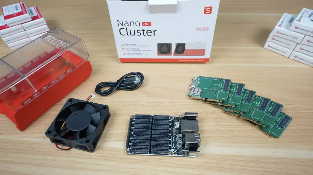
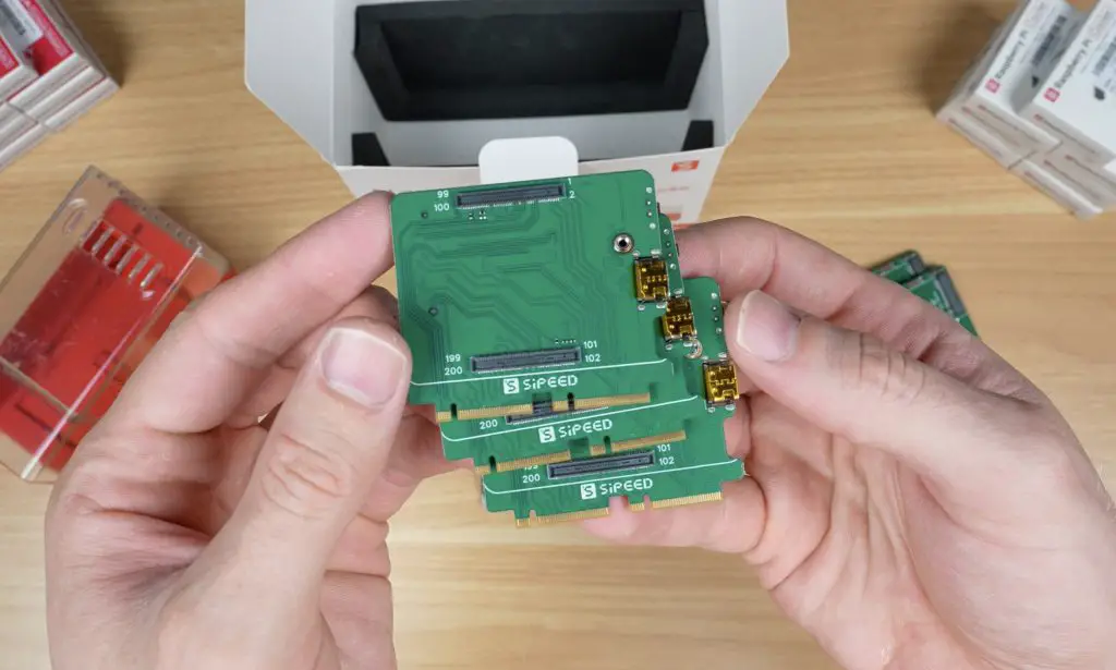
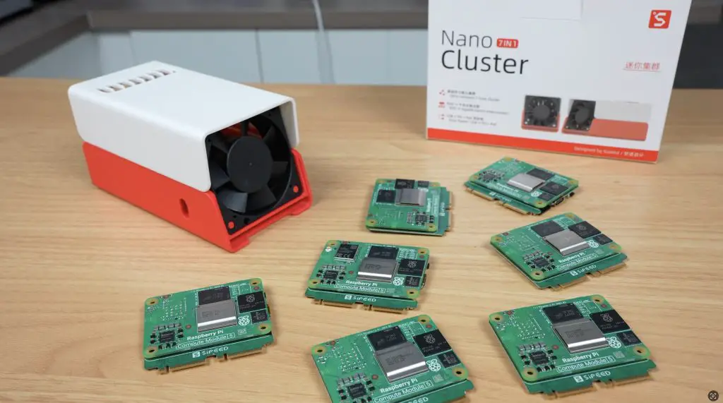
Sipeed sent me what appears to be their CM45 package, which includes the Nanocluster board, fan, and seven adapter boards for Raspberry Pi CM4 or CM5 modules (with a small caveat I’ll get to later). This kit sells for $99. They also included a 3D-printed two-part enclosure with clear and white top options. It doesn’t seem to be part of the preorder packages yet, but Sipeed has shared the 3D print files on Makerworld, so you can print your own if you’d like to.
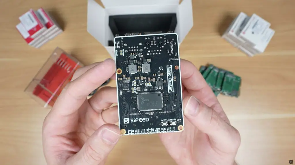
Exploring the Nanocluster Board
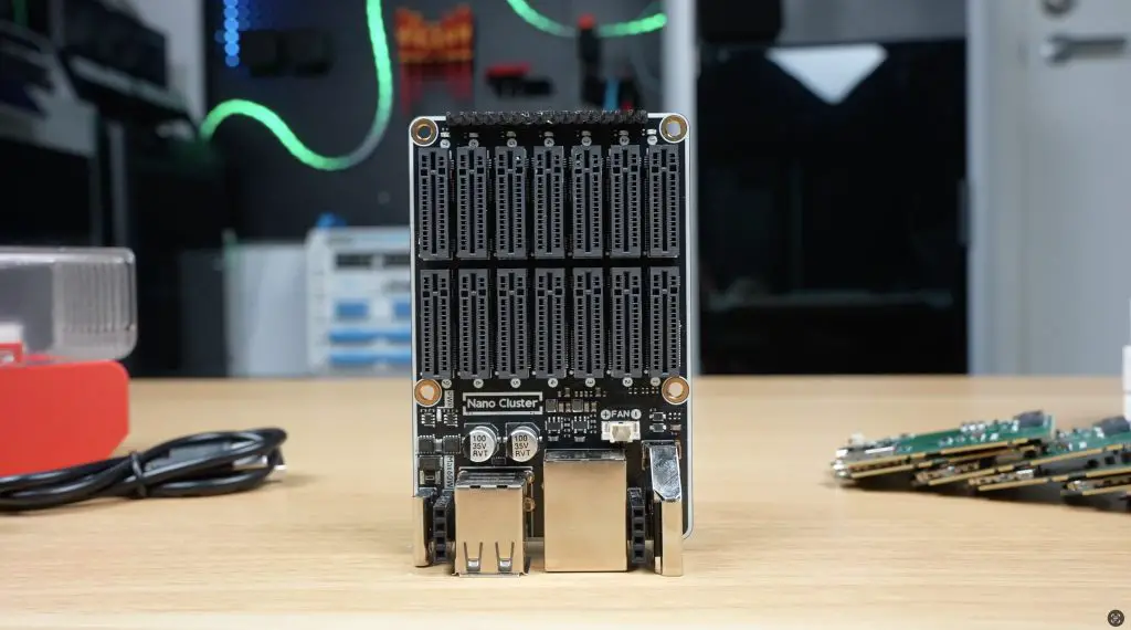
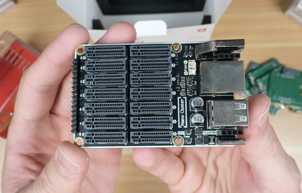
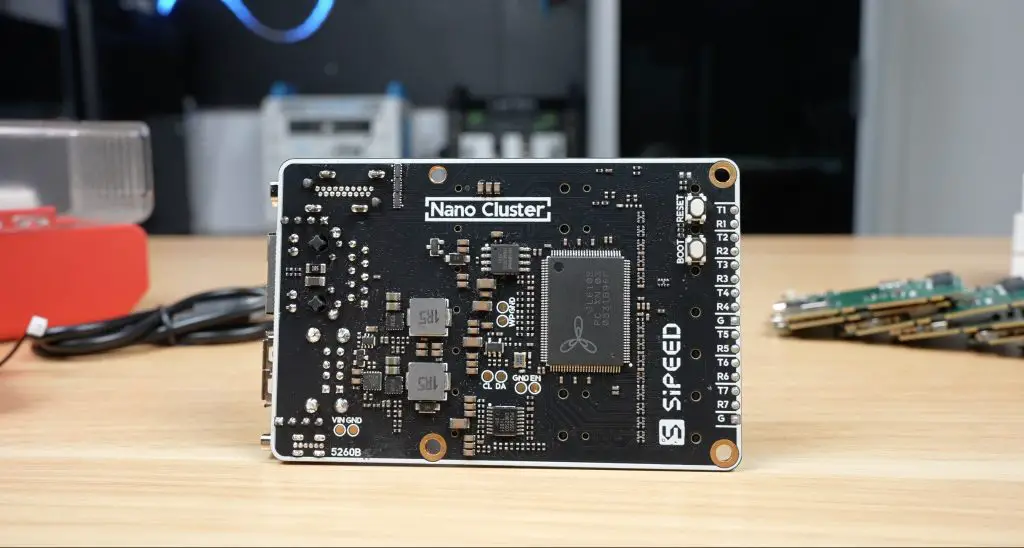
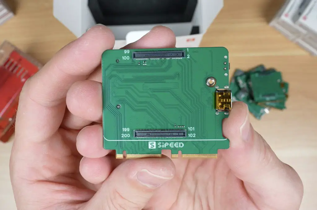
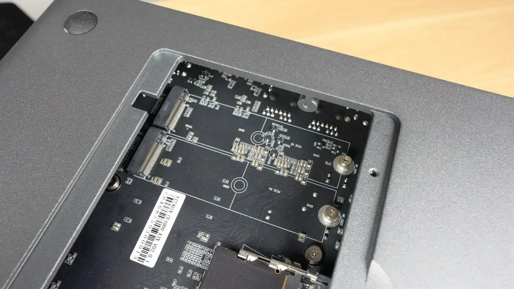
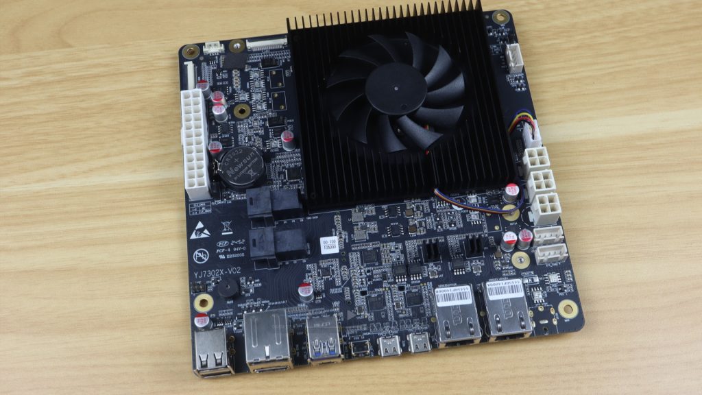
The Nanocluster board itself features seven SOM (System on Module) slots, each using dual M.2 M-key vertical connectors. These connect to an 8-port RISC-V-based gigabit managed switch located at the bottom of the board. The switch includes a web dashboard for configuration, somethingthat’s quite nice to see in such a tiny setup.
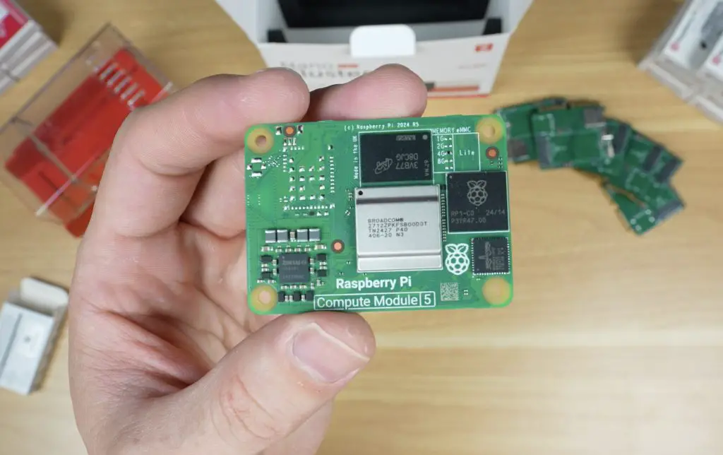
The slots are directly compatible with Sipeed’s Longan 3H as well as their M4N module and Raspberry Pi CM4 and CM5 modules via the included adapter boards. You can even mix and match different module types if that suits your project.
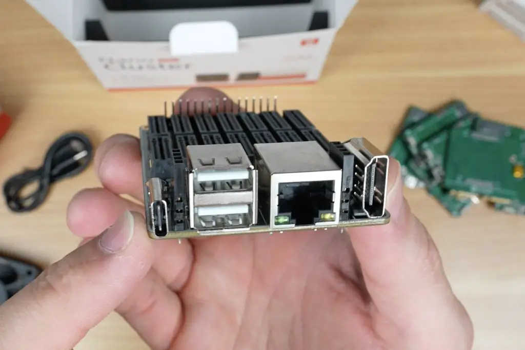
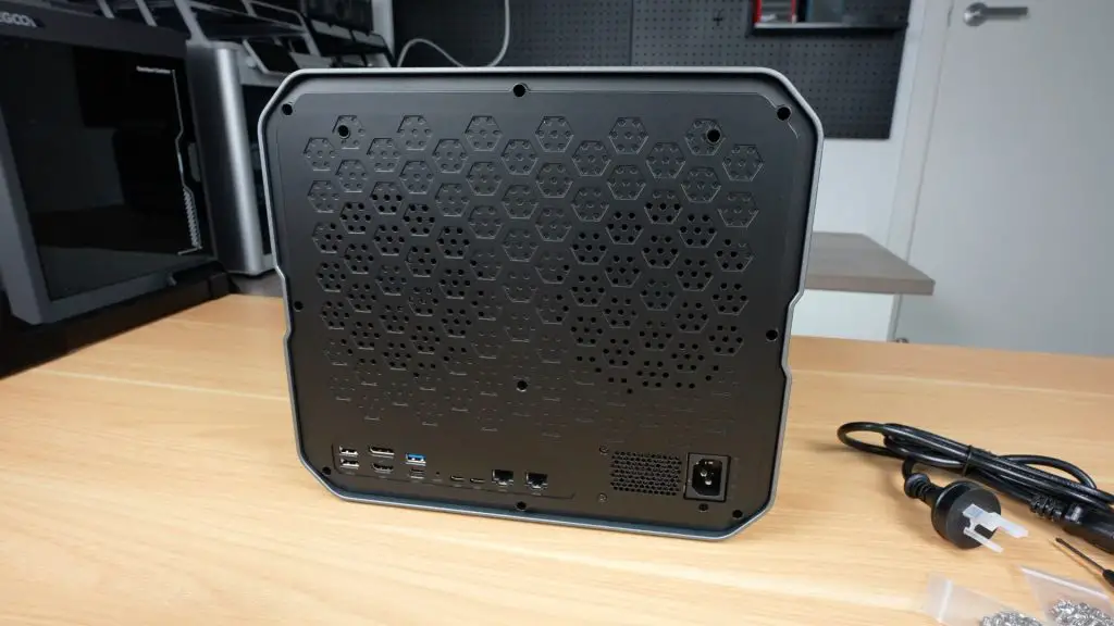
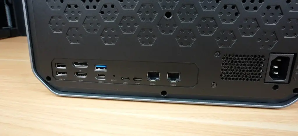
For power, the board uses a USB-C port supporting up to 20V (65W) or an optional PoE expansion module (up to 60W). Both can be connected simultaneously for power redundancy, so your cluster keeps running even if one source drops out. It’s a thoughtful design that eliminates the usual mess of cables and power bricks. With your modules installed, you just plug in a power supply and Ethernet cable, or a single PoE cable, and you’re ready to go.
Alongside the USB-C port, you’ll find two USB 2.0 ports, a gigabit Ethernet port, and an HDMI port. These are all connected to slot 1, which acts as the master node and can manage power for the other slots too.
Cooling and Connectivity
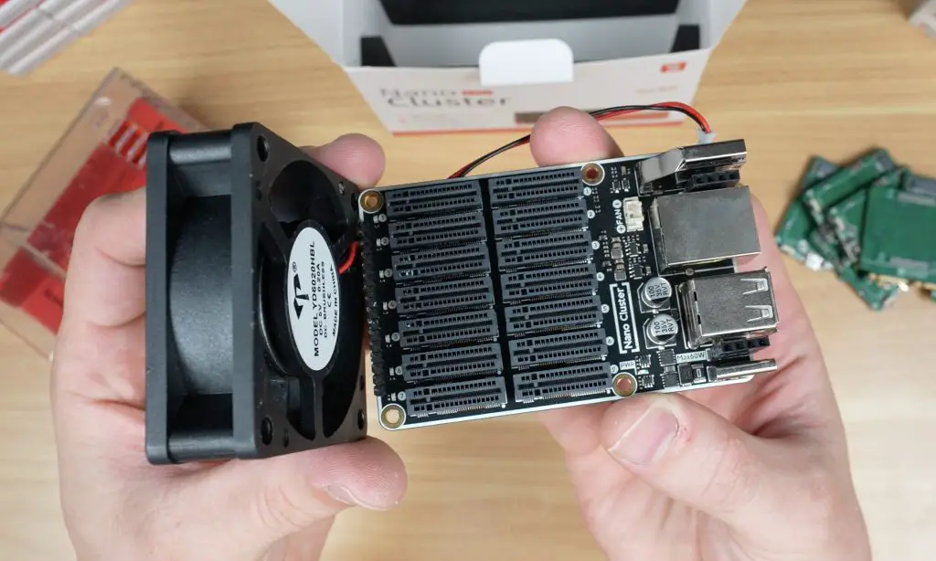
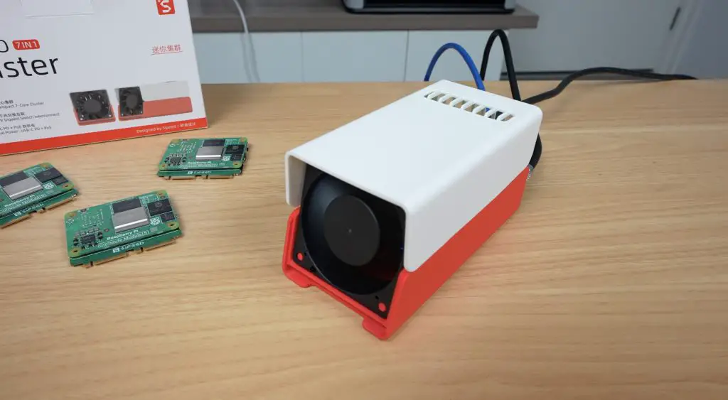
Mounted to the back of the enclosure is a 60mm 5V fan. It’s a simple two-pin fan that runs at full speed permanently, it’s not PWM controlled, so it’s a bit noisy, but it ensures all modules stay cool regardless of what’s running.
In front of the fan are seven indicator LEDs showing the status of each node, and seven UART ports for debugging and control.
The board measures just 88 x 57 mm, or the whole assembly is roughly 100 x 60 x 60 mm with the fan and modules installed.
Computer Module Adapter Boards
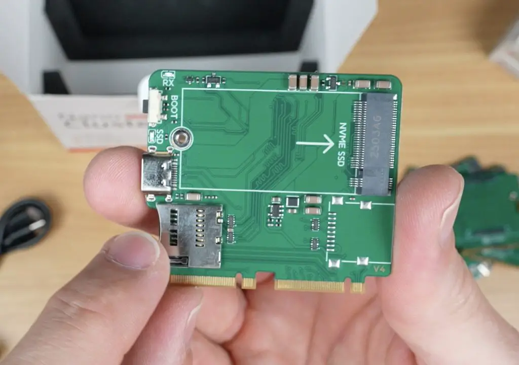
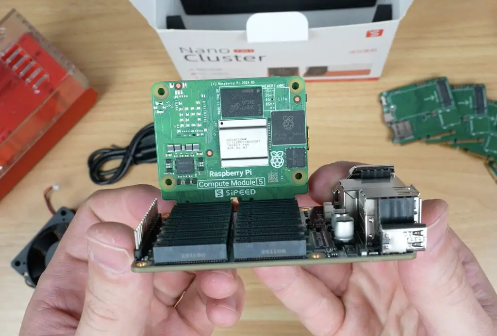
If you’re using Sipeed’s LM3H modules, you don’t need adapters. But if you’re running Pi CM4, CM5, or M4N modules, these adaptor or carrier boards are required.
Each adapter board includes:
A connector for the compute module
A USB-C port for flashing
A boot button
A microSD card slot for the OS image
An M.2 slot (2230/2242) for an NVMe SSD
In terms of performance, the LM3H modules are the most affordable option, while the M4N modules offer the most processing power, featuring up to eight cores.
Power and Thermal Limits
As compact as the Nanocluster is, there are some limitations. Because of its 60W power limit and small form factor, you can’t populate all seven slots with high-power modules.
Sipeed recommends:
Up to 4 CM5 or M4N modules (especially with SSDs or PoE)
Up to 6 CM4 or LM3H modules
All 7 slots only if you’re using CM4s without SSDs and powered via USB-C PD
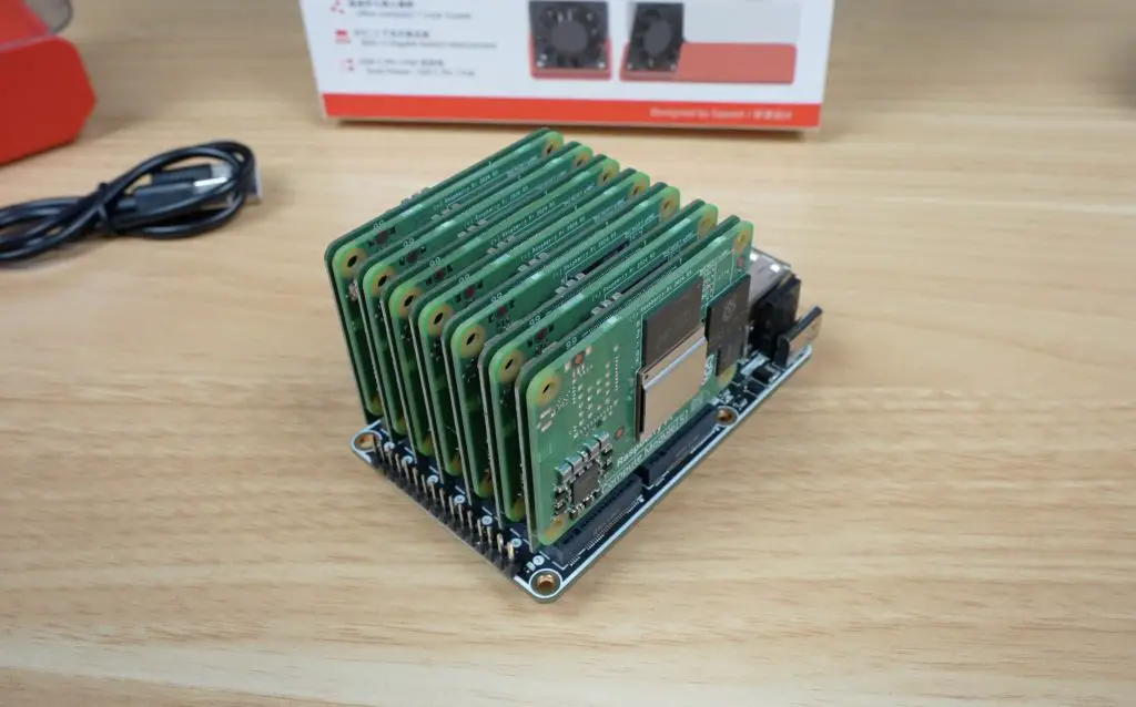
Space is also a factor, if you’re using heatsinks and SSDs, you’ll likely only fit four modules comfortably, skipping every other slot for airflow.
Setting Up the Cluster
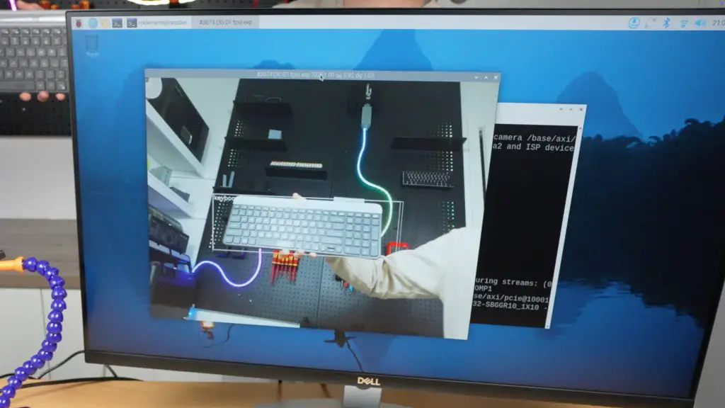
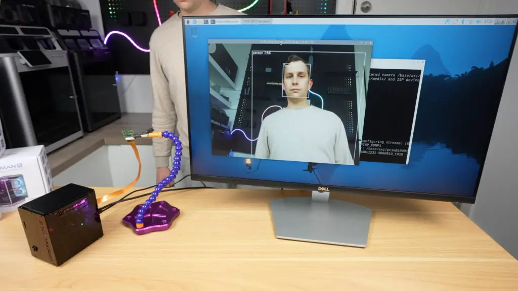
For testing, I used four Raspberry Pi CM5 Lite modules (no Wi-Fi or Bluetooth) and microSD cards for storage. I also tried to use the official CM5 heatsinks, but they were too thick to fit, so I ran the tests without them. More on this during my thermal tests.
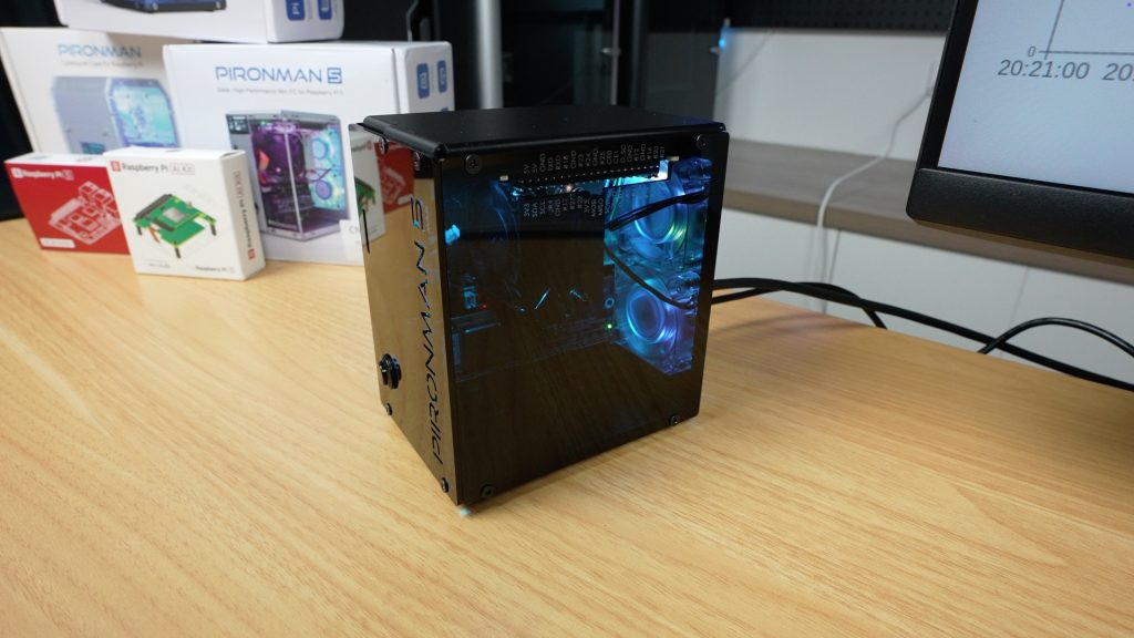
Once the modules were installed in their adapters and plugged into the board, I set up the cluster in the enclosure and prepared for some benchmarks.
Performance Testing
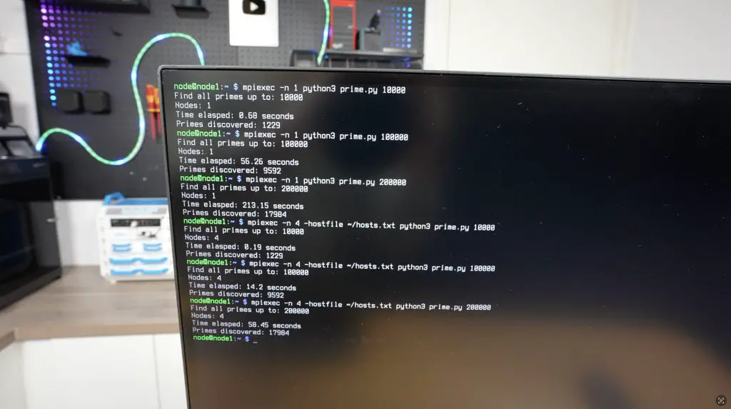
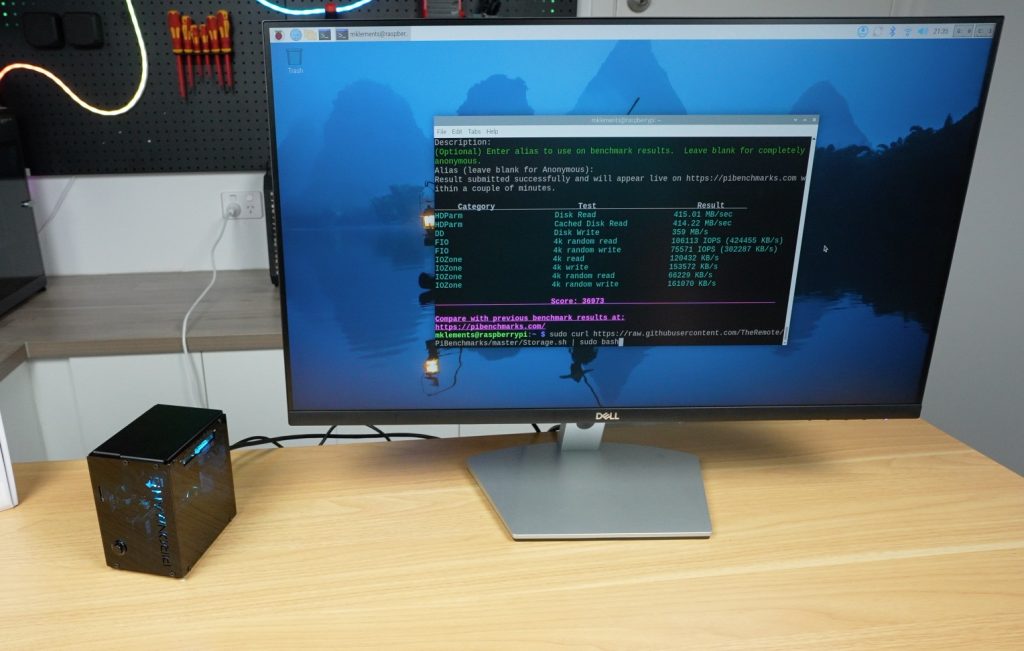
To test the cluster, I ran the prime number test script I used a few years ago on my 8-node water-cooled Pi cluster. The Python script checks each number up to a defined limit to see if it’s prime. It’s intentionally inefficient and CPU-intensive, perfect for testing performance scaling.
I ran the test three times per setup (single node vs. 4-node cluster), with limits of 10,000, 100,000, and 200,000.
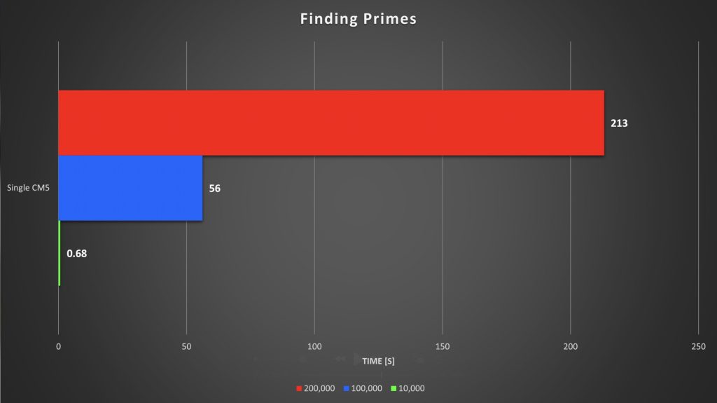
Single Node Results:
10,000 → 0.68s
100,000 → 56s
200,000 → 213s (≈4 minutes)
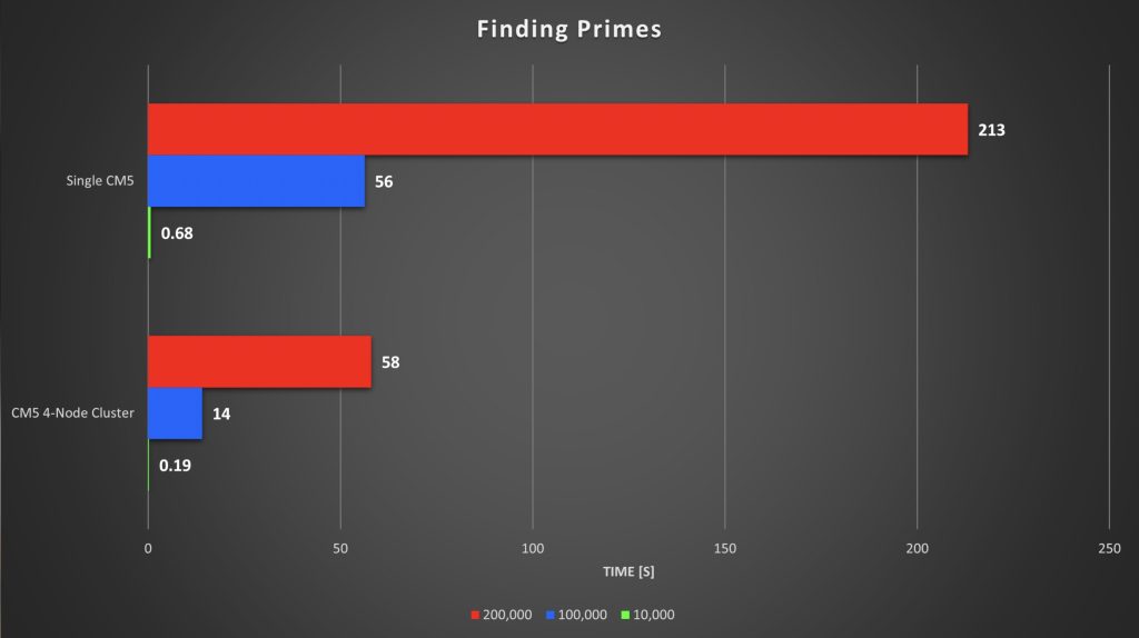
4-Node Cluster Results:
10,000 → 0.19s
100,000 → 14s
200,000 → 58s
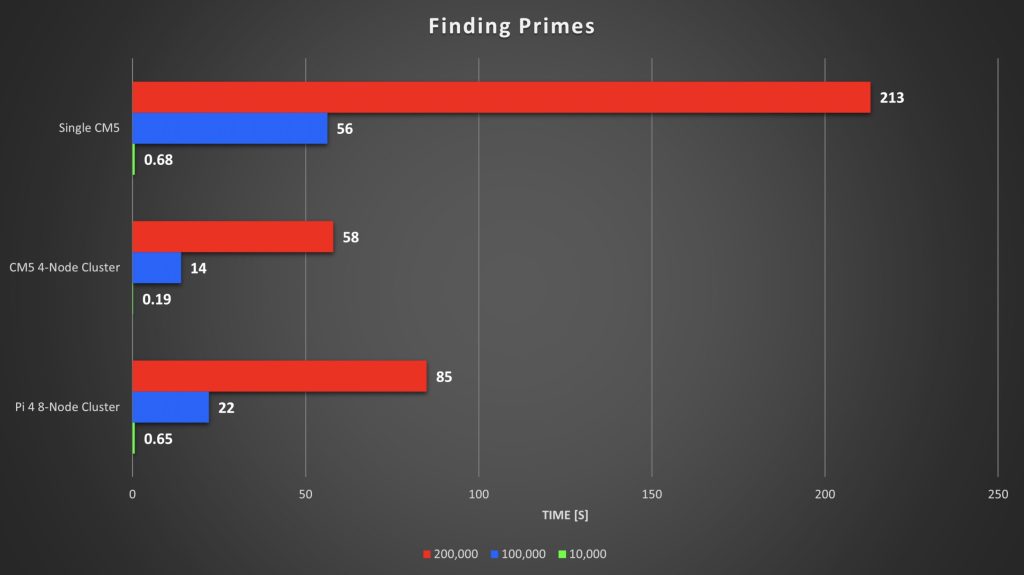
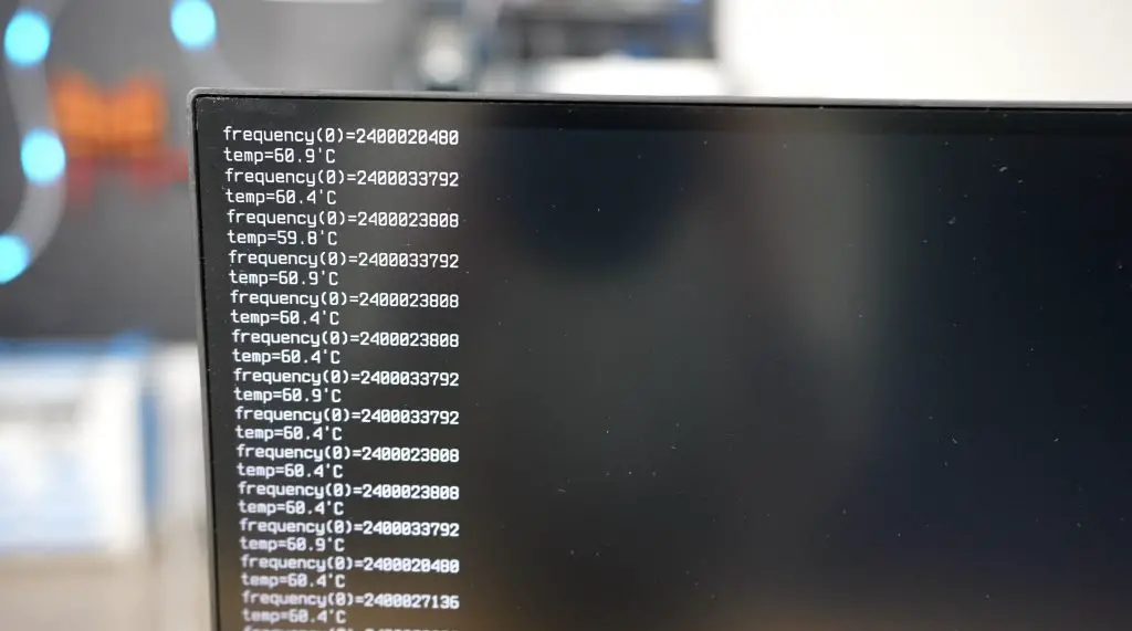
Each test ran roughly four times faster across the cluster, and the 4-node Pi 5 cluster even beat my old 8-node Pi 4 cluster, despite the Pi 4s being overclocked to 2.0GHz. The Pi 5s, running at stock 2.4GHz, showed how much progress the hardware has made.
Thermal and Power Tests
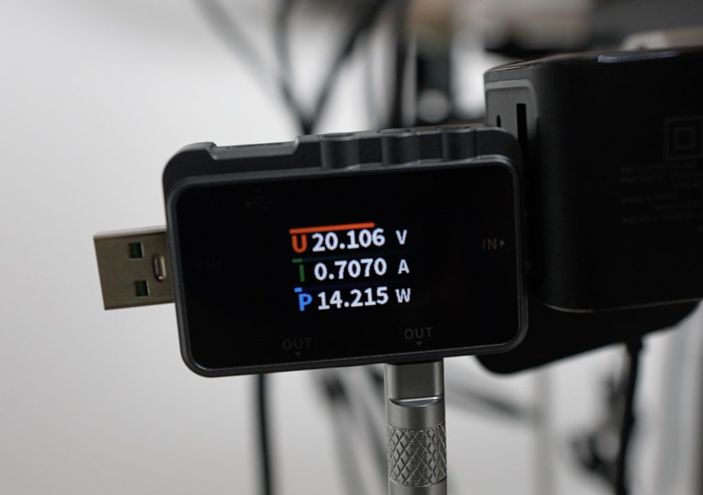
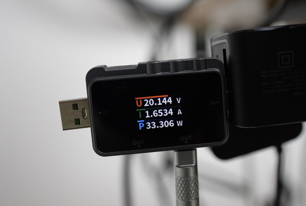
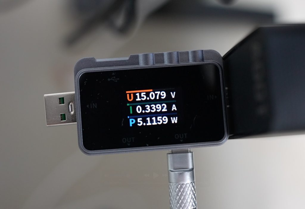
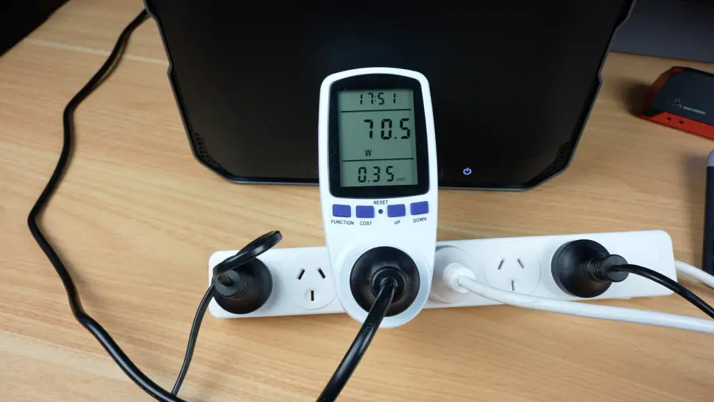
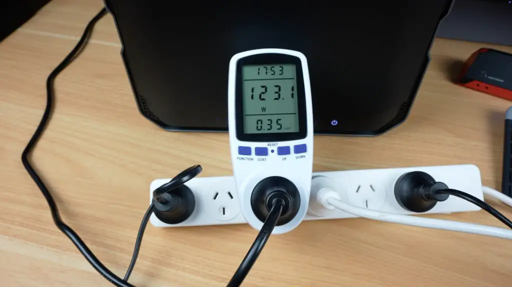
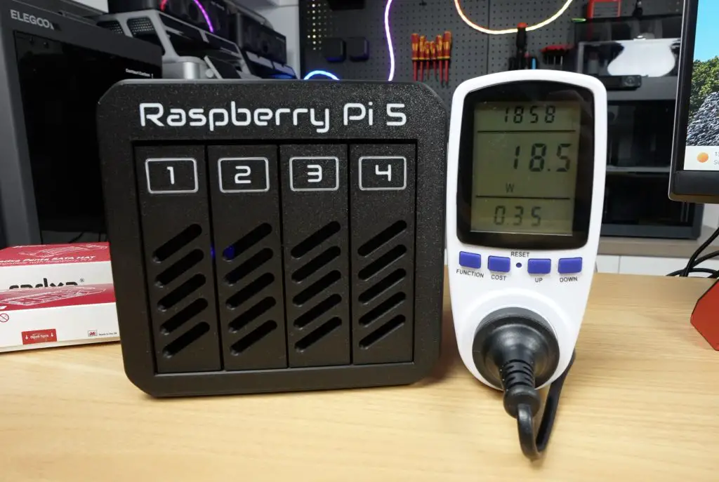
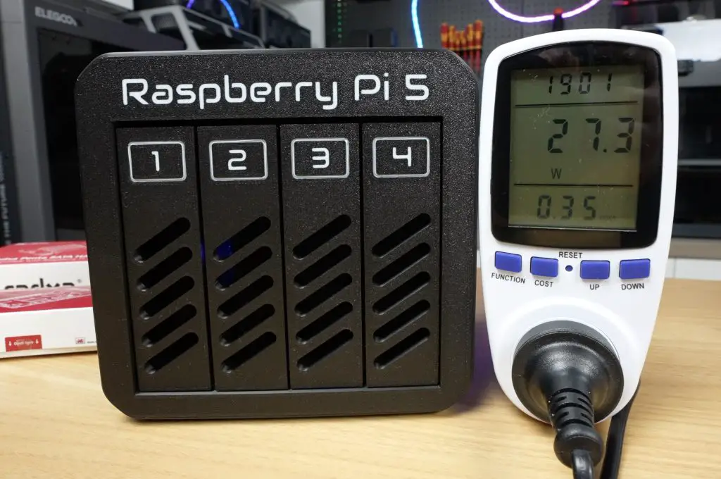
At idle, the cluster drew about 14W, which is around 2.5W per Pi, plus 3.5W for the board. Under full CPU load using cpuburn, total consumption rose to 33W, which is an increase to around 7.5W per Pi.
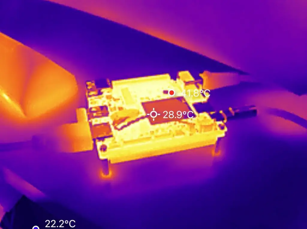
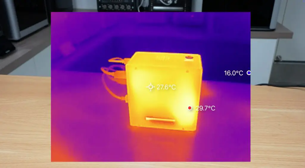
Thermally, the results were excellent. Even without heatsinks, temperatures started around 26–29°C and stabilised at around 60°C after 30 minutes of full load. The large fan does a great job pushing air across the exposed CPU heat spreaders, keeping all nodes within safe limits. The outer modules ran a bit warmer, but still comfortably low.
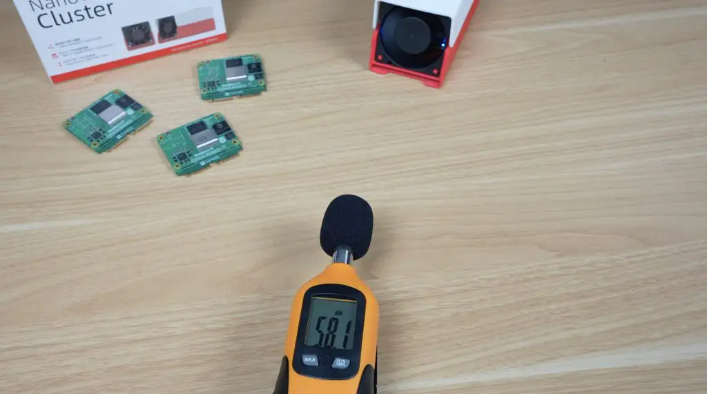
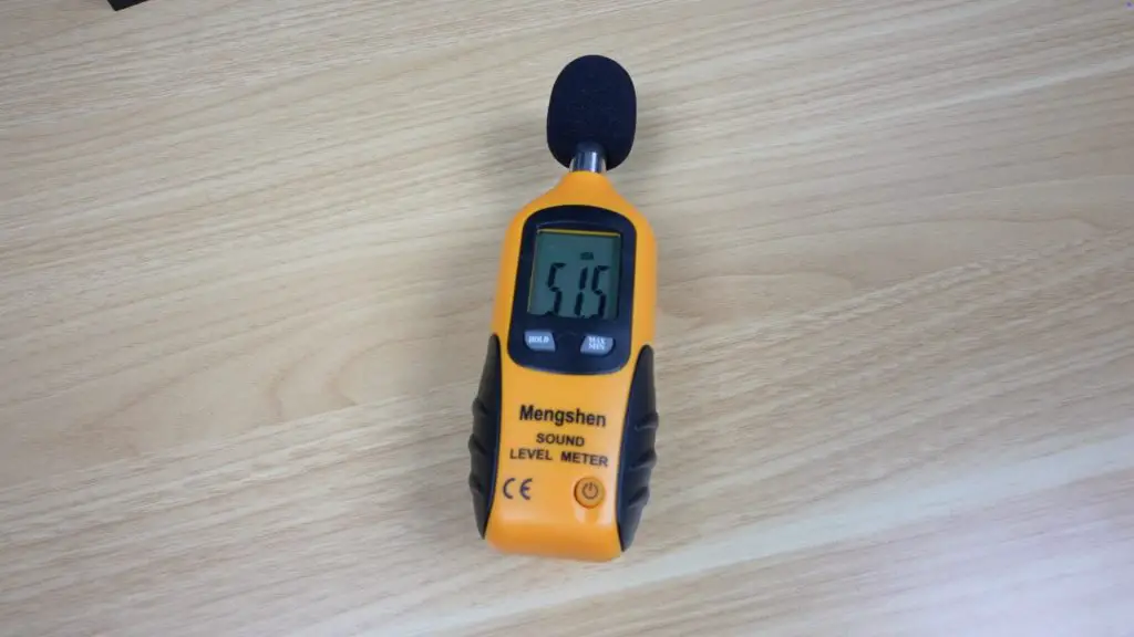
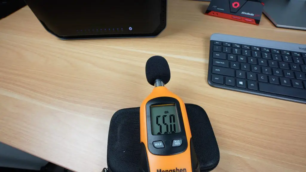
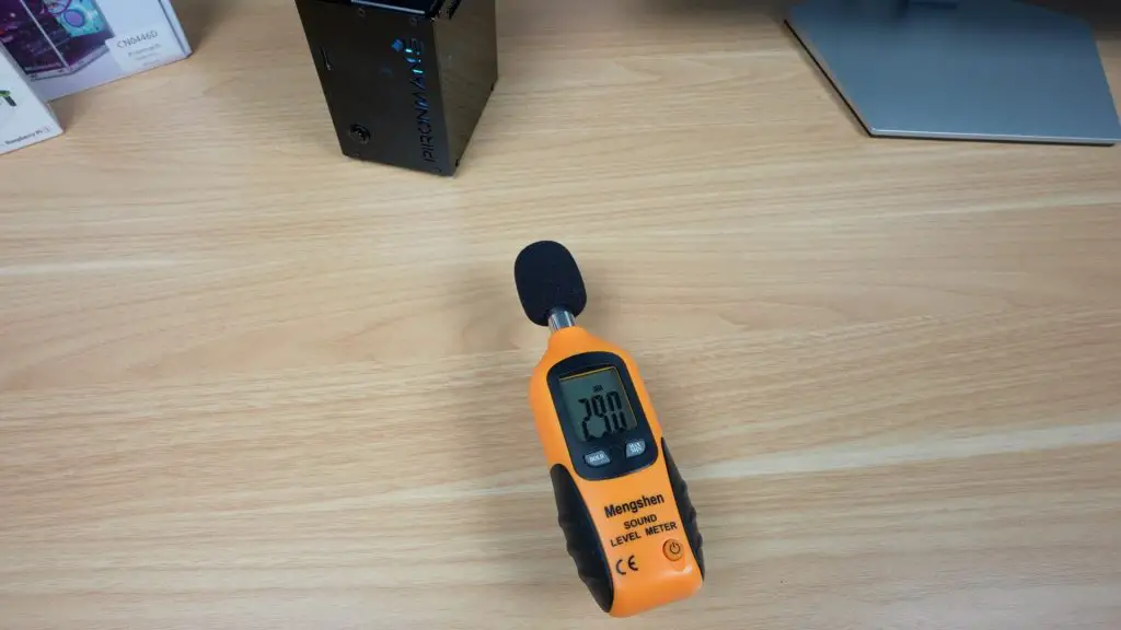
Fan noise measured about 58dB, which is noticeable but not unbearable for a lab setup.
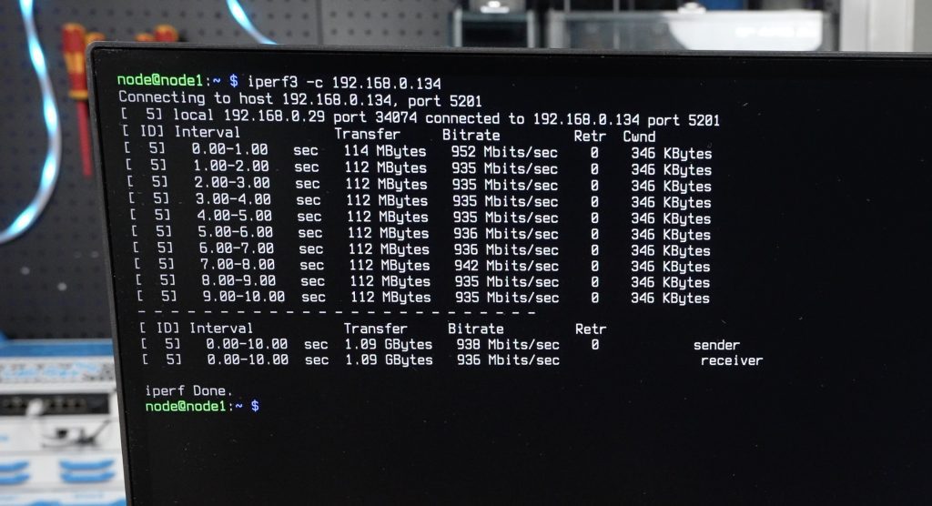
Network Performance
I also ran an iPerf network test between nodes, and each link hit around 950 Mbps, which is right on target for gigabit networking.
Final Thoughts
The Sipeed Nanocluster is an impressive little system that makes cluster computing accessible and tidy. It packs power delivery, cooling, and an integrated managed switch into a form factor smaller than your palm.
I really appreciate that Sipeed thought about practical usability, power redundancy, active cooling, and clean integration all make this much easier to work with than a DIY setup full of cables and adapters.
It’s obviously not going to replace your cloud server or main NAS, but as a learning platform, IoT hub, or compact homelab, it’s a brilliant piece of hardware. And at under $100 for the board and adapters, it’s hard to beat.
What would you run on your own Nanocluster? Let me know in the comments section below and if you’re curious to see it in action, check out the video on my YouTube channel.
LattePanda’s latest release, the IOTA, packs Intel’s new N150 processor into a board barely larger than a Raspberry Pi. Despite its small size, it’s packed with features and IO aimed squarely at makers who want desktop-class power with microcontroller flexibility.
In this review, we’ll unbox the LattePanda IOTA, take a look at its hardware and available accessories, then boot it up to test video playback, run some benchmarks, and check its power consumption and thermal performance.
Here’s my video review of the LattePanda IOTA, read on for the written review;
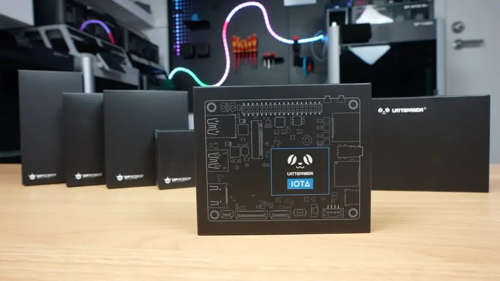
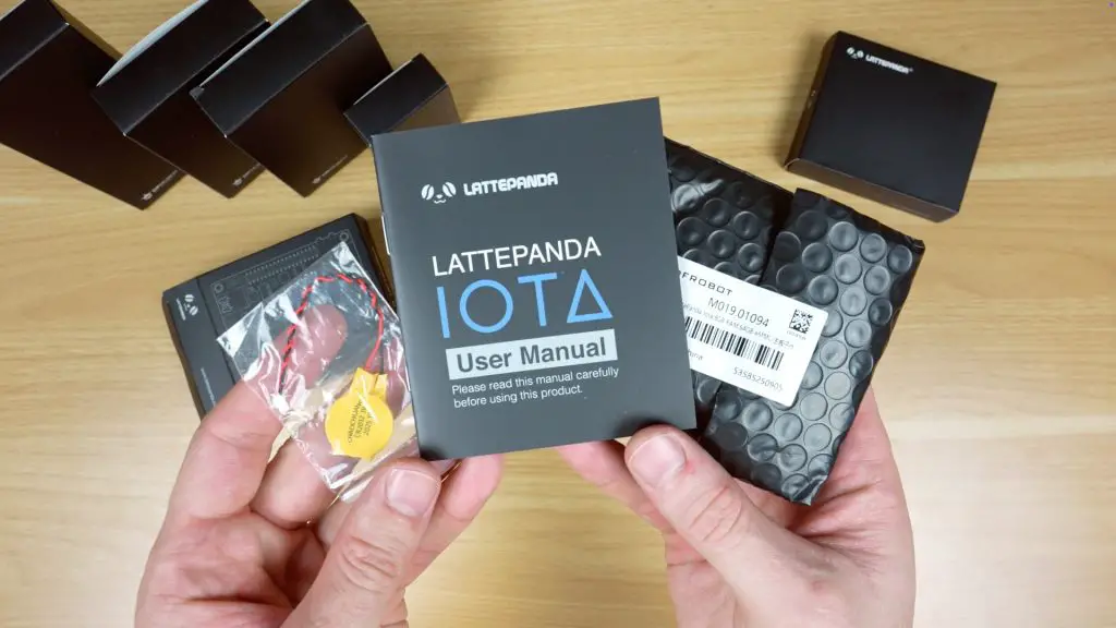
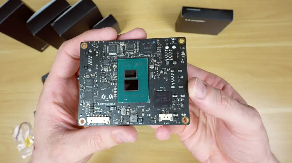
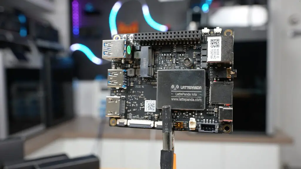
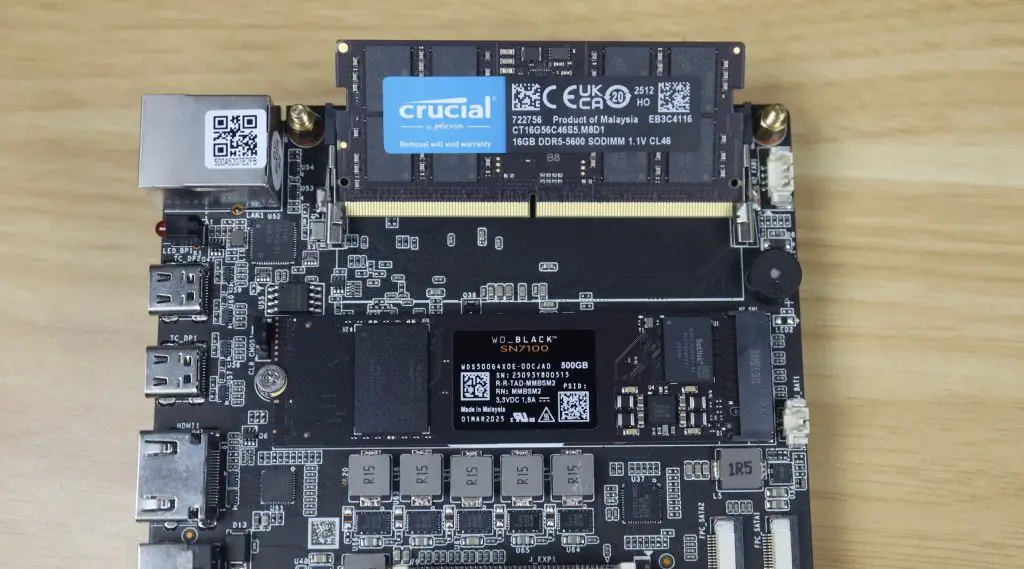
The LattePanda IOTA is a single-board computer (SBC) available in several kit configurations with optional add-ons. I’ve got a few of those accessories here as well, which we’ll explore later. In the box is the IOTA, a user manual and a battery for the real-time clock.
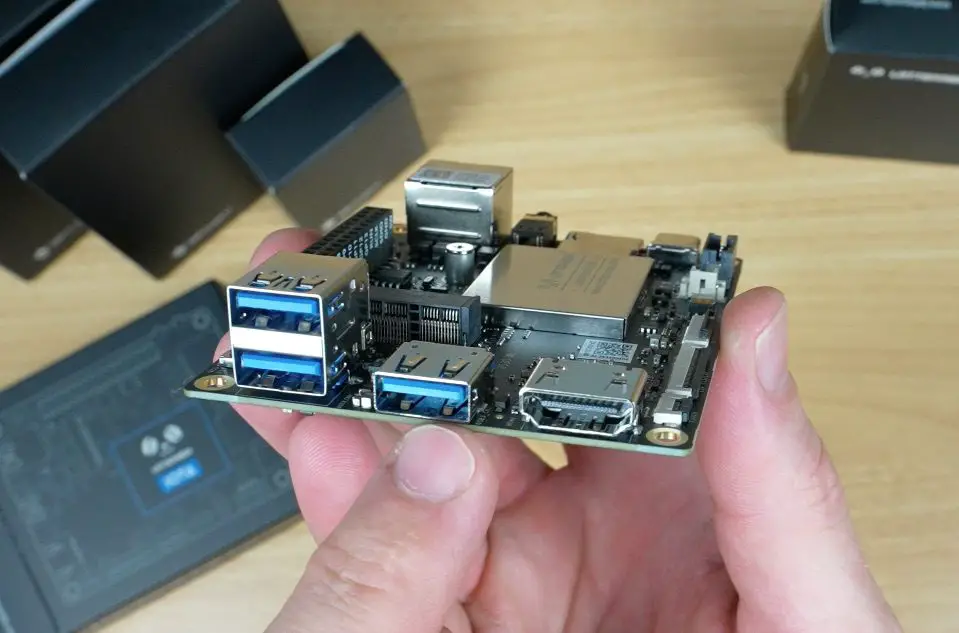
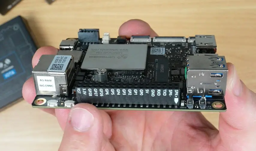
The board measures just 88mm x 70mm x 19mm, making it impressively compact for what it offers. It keeps the same dimensions and general port layout as the original LattePanda V1, meaning it’s compatible with most existing enclosures, perfect for anyone looking to upgrade or drop it into an older build.
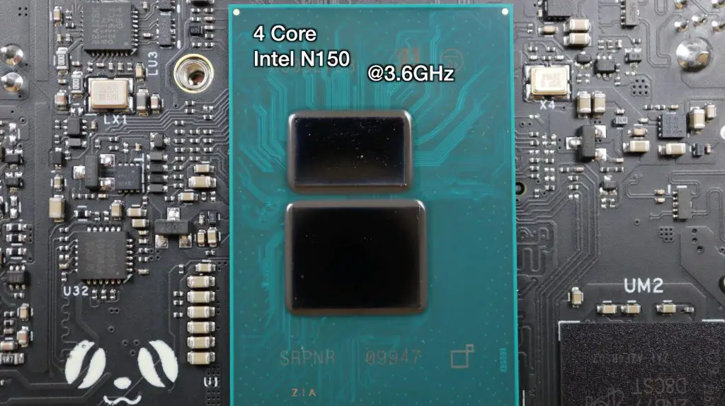
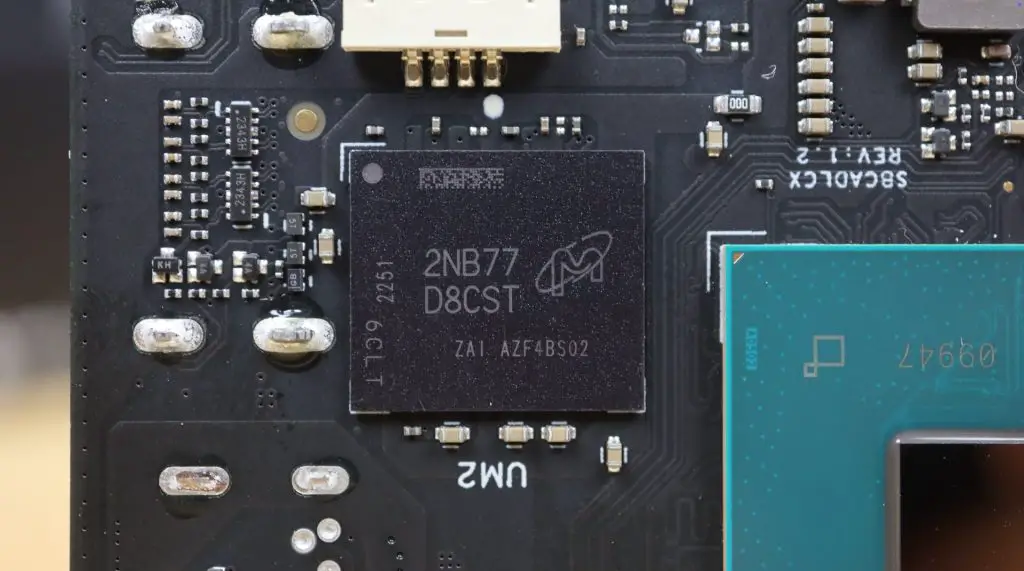
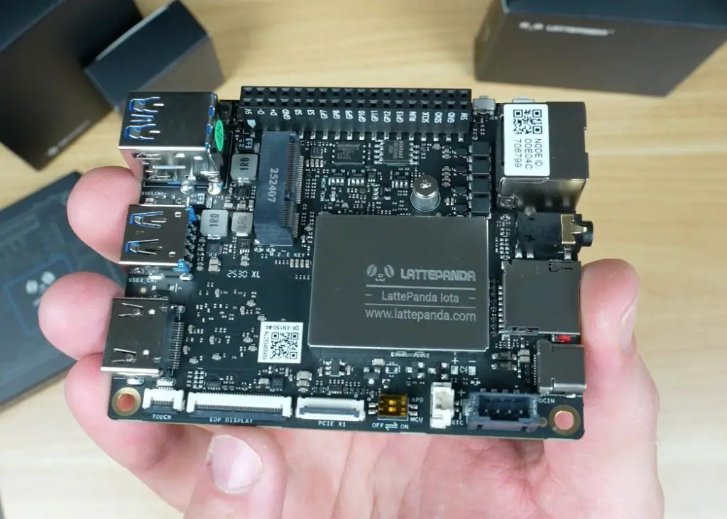
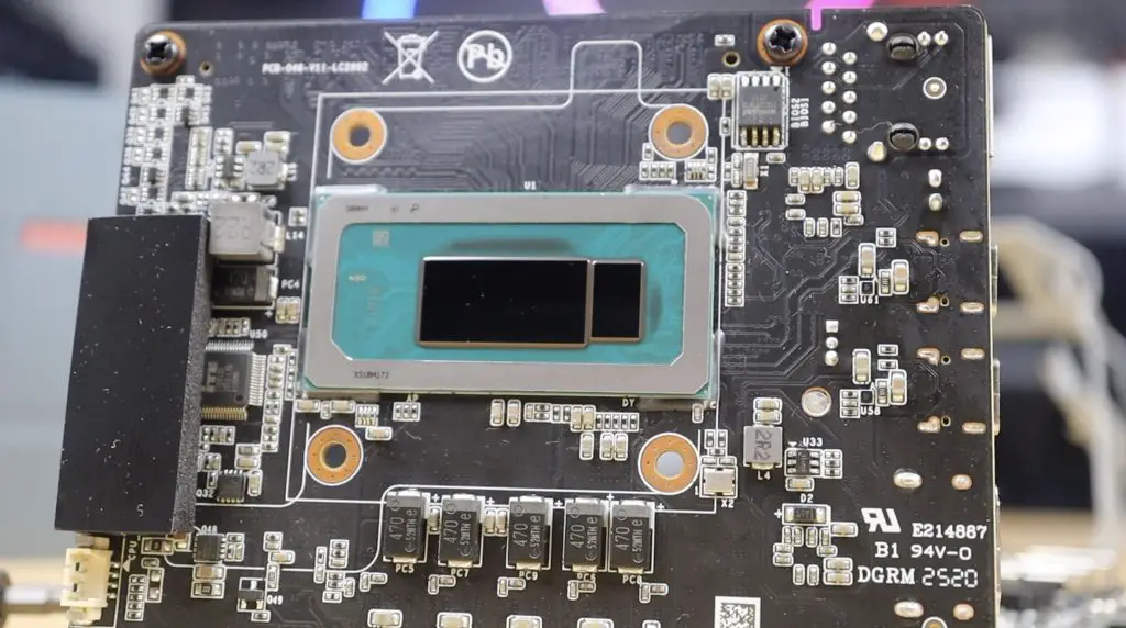
At first glance, you might think the CPU is on the top side, but it’s actually mounted on the back. The IOTA uses a 4-core Intel N150 CPU running up to 3.6GHz, paired with LPDDR5 RAM at 4800MT/s, available in 8GB and 16GB variants.
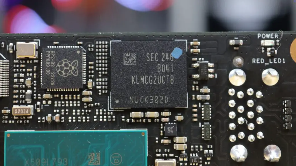
For storage, it includes onboard eMMC. It’s got 64GB on the 8GB RAM version, and 128GB on the 16GB version. The model I’m reviewing has 8GB of RAM and 64GB of storage.
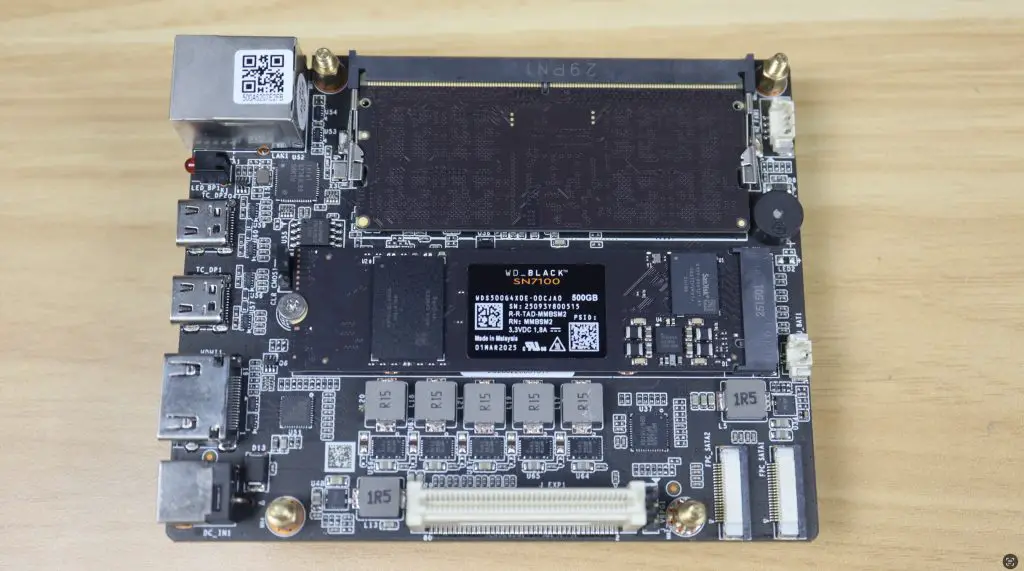
Hardware Overview
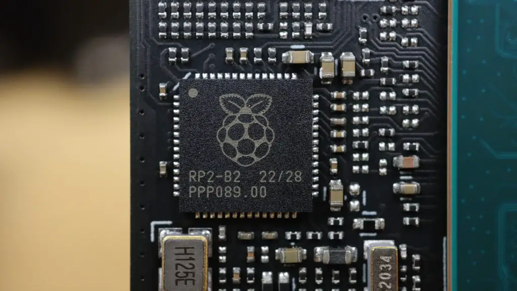
One of the standout features of the IOTA is its onboard RP2040 microcontroller, which sets it apart from most x86-based mini PCs. This dual-core Cortex coprocessor manages I/O through the GPIO pins, similar to how the Raspberry Pi handles hardware interfacing.
Looking around the board:
On the bottom, there’s a power management connector for alternative power options and a fan connector.
On the top, you’ll find all the ports and interfaces:
Three USB 3.2 ports
HDMI 2.1 port (supports 4K @ 60Hz)
I2C connector for touch displays
eDP display connector
PCIe 3.0 x1 interface (similar to the Raspberry Pi 5)
Battery connector
USB-C Power Delivery input
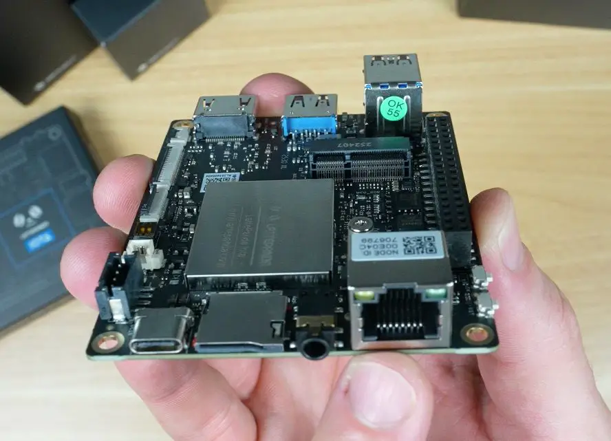
MicroSD card slot
Headphone jack
Gigabit Ethernet port
Power and reset buttons
GPIO header
MCU reset and boot buttons
M.2 E-key slot for adding a Wi-Fi adapter.
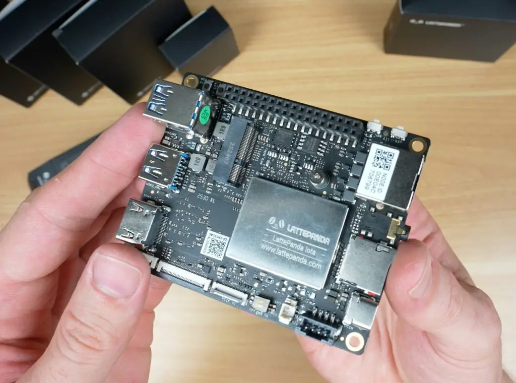
The IOTA has a configurable TDP between 6W and 15W, letting you balance performance and thermals. At lower settings, it can run silently with a passive heatsink; crank it up, and you’ll want the active cooler (which I’m using for this review).
Pricing
I think the LattePanda IOTA is priced fairly well;
8GB RAM / 64GB storage – $129
16GB RAM / 128GB storage – $175
You’ll want to budget an extra $12 for the cooler, bringing the total to under $150 for the base setup. I think this is fair for what you are getting.
Optional Add-Ons
LattePanda also offers several add-ons to expand the IOTA’s functionality:
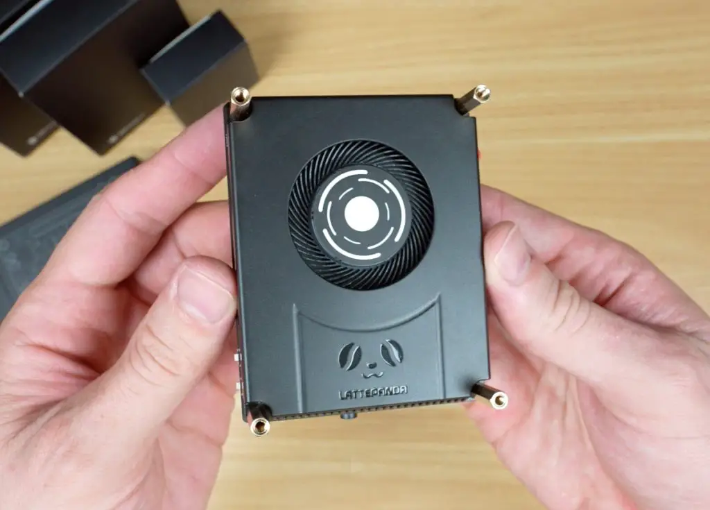
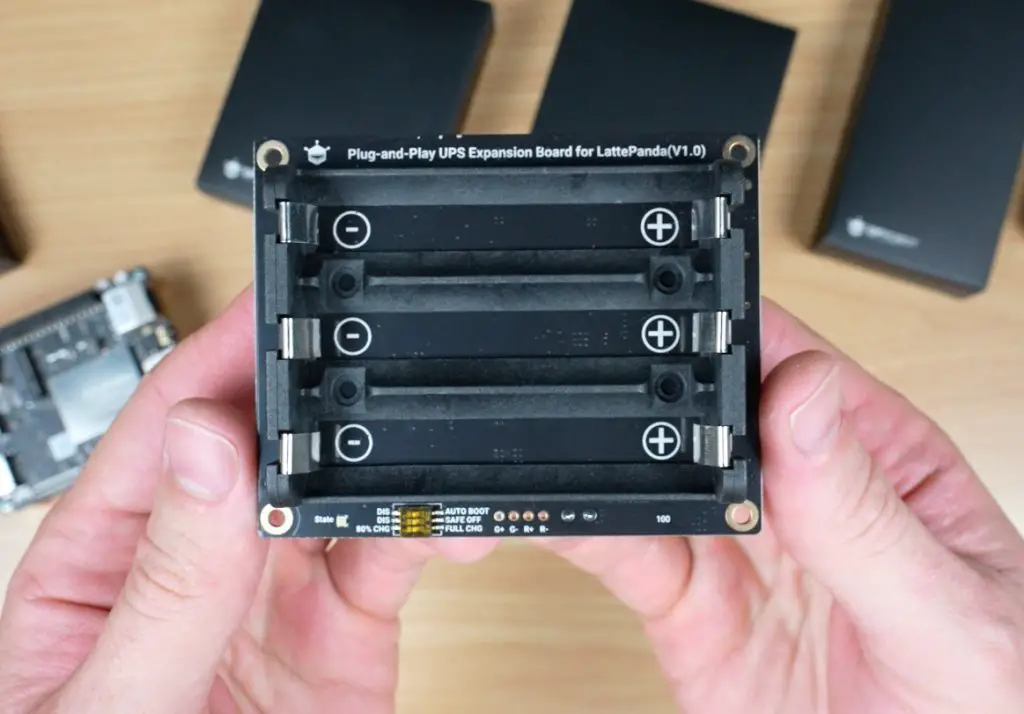
Smart UPS Hat
A plug-and-play uninterruptible power supply, capable of keeping the IOTA running for up to 8 hours depending on the batteries you use. It includes smart features like automatic power-on and safe shutdown when voltage gets too low, connecting via the IOTA’s power management connector.
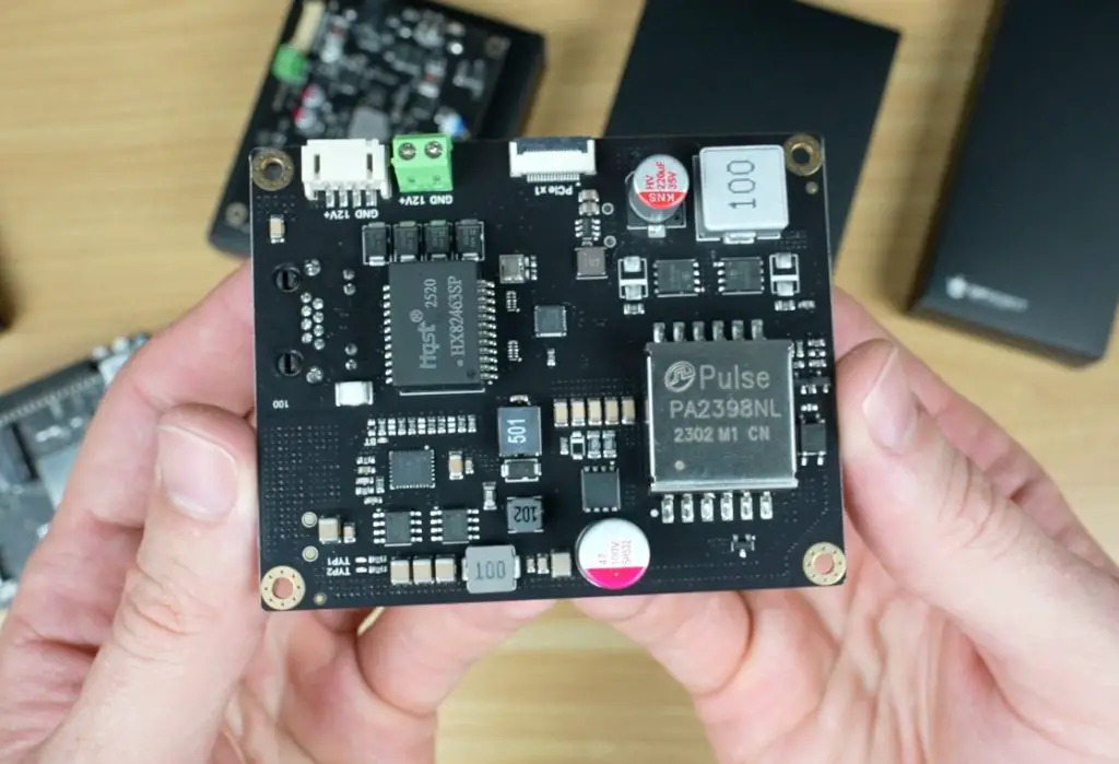
51W PoE++ Expansion Hat
This expansion board lets you power the IOTA via Ethernet through its onboard gigabit port. It connects to the IOTA’s power input and PCIe port, effectively giving you two network ports.
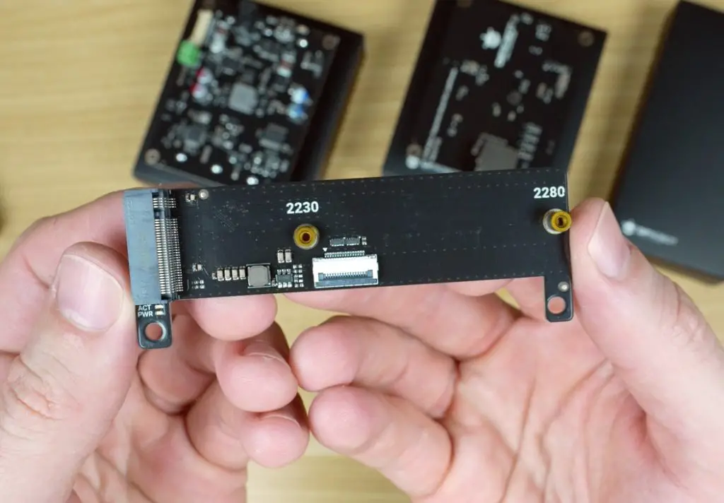
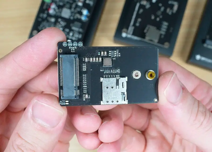
M.2 Expansion Boards
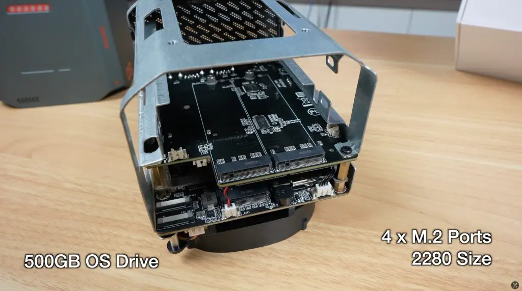
There are two M.2 expansion options available for the IOTA:
One with an M-key slot for NVMe SSDs (2230 or 2280 sizes).
Another smaller one for a 4G LTE module for mobile connectivity.
The NVMe board connects through PCIe, while the LTE board uses a USB 2.0 interface via the GPIO pins.
Performance Testing The LattePanda IOTA
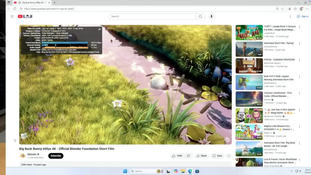
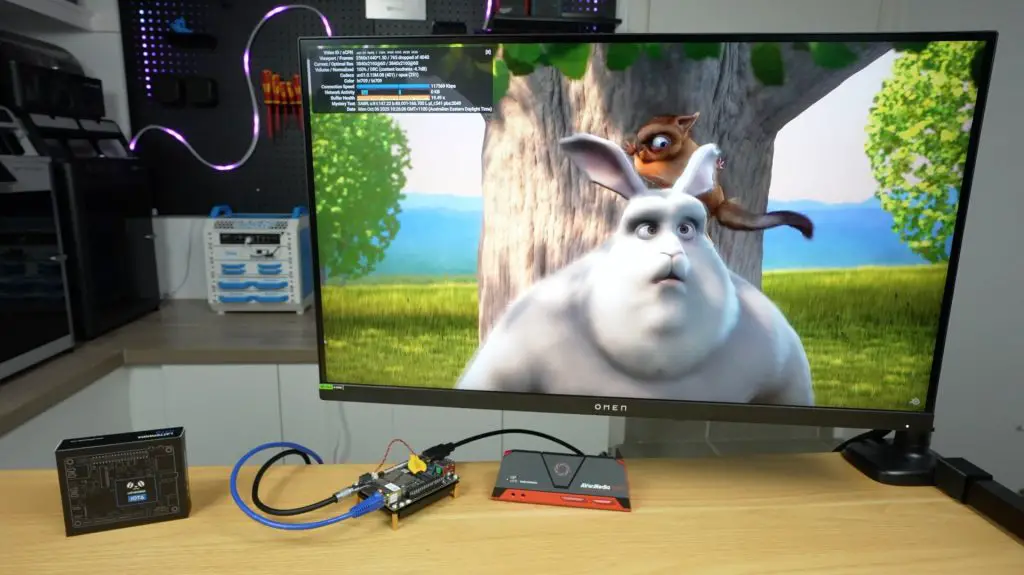
Video Playback at 1080P and 4K
For testing video performance, I ran playback at both 1080p and 4K, setting the system display resolution to match each test.
1080p playback both in a window and fullscreen ran perfectly, with no dropped frames.
4K playback dropped some frames, both windowed and fullscreen, but remained smooth enough for casual use. It’s near the performance limit, but still usable.
Benchmarks
I then ran a few standard benchmarks to get a sense of performance:
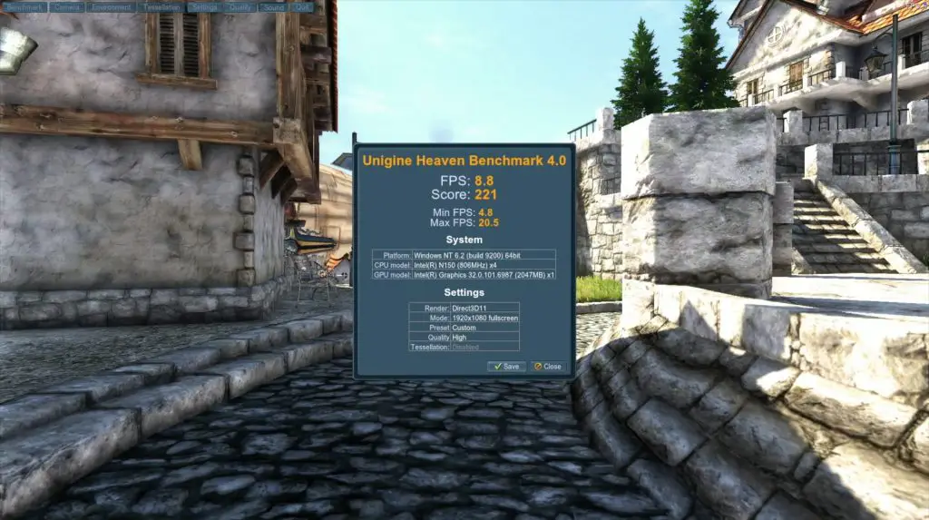
Unigine Heaven (1080p, High Quality)
Score: 221 points
Frame rate: 5–20 FPS
As expected, this isn’t a gaming system. The integrated graphics can handle light 3D workloads, but performance is roughly on par with other Intel N100 systems.
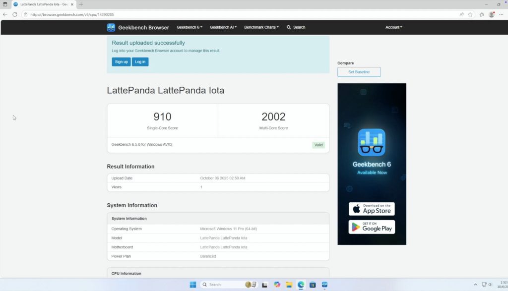
Geekbench 6
Single-core: 910
Multi-core: 2002
That’s enough for everyday tasks like browsing, media playback, and light productivity. It’ll struggle with heavier workloads like video editing or gaming.
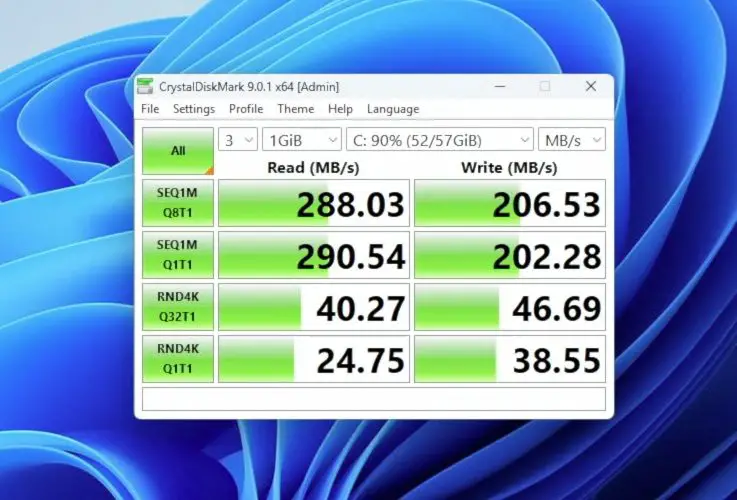
CrystalDiskMark (eMMC Storage)
Sequential Read: 288 MB/s
Sequential Write: 206 MB/s
4K Random Read/Write: ~40 / 46 MB/s
The onboard storage feels snappy for booting and launching apps, but it’s far slower than NVMe storage.
Power and Thermal Performance
At idle, the IOTA draws about 3–5W, rising to 15W under a full CPU and GPU load, with spikes up to 19W.
Reducing the TDP to its minimum 4W limit drops total draw to around 5W, but performance takes a big hit. Windows 11 becomes laggy, so a lightweight OS would be better suited for that mode. Still, it’s impressive that an x86 board running Windows can idle that low.
Thermals with the active cooler are solid:
Idle: 45–50°C
Full Load: ~70°C
Fan noise is the only real issue that I encountered with this board. It runs at 34–35 dB at idle (20cm away) and up to 50 dB under full load. The tone is fairly high-pitched, which makes it more annoying than the numbers suggest.
GPIO and Maker Features
Since the IOTA is designed for makers, the GPIO pins and RP2040 microcontroller are central to its appeal, and they’re very easy to use.
For a quick test, I connected two LED to the GPIO pins through 220Ω resistors, then opened the Arduino IDE directly on the IOTA. Selecting the RP2040 board profile, I uploaded a basic blink sketch and the LEDs flashed as expected.
That means you get the full power of an Intel PC plus a built-in microcontroller for sensors, motors, or other real-time hardware control, with no extra boards required.
Final Thoughts on the LattePanda IOTA
The LattePanda IOTA is a compact, power-efficient, and feature-rich little board that bridges the gap between a mini PC and a maker’s microcontroller platform.
The integrated RP2040 is what truly sets it apart, allowing hybrid projects that combine PC-level processing with real-time hardware control for robotics, automation, or experimental electronics.
If you’re looking for a cheap everyday mini PC, there are better options for pure desktop use. But if you’re a maker who wants something you can build projects with, the IOTA is a strong and flexible choice.
Let me know in the comments what you think of the LattePanda IOTA and what kinds of projects you’d use it for.
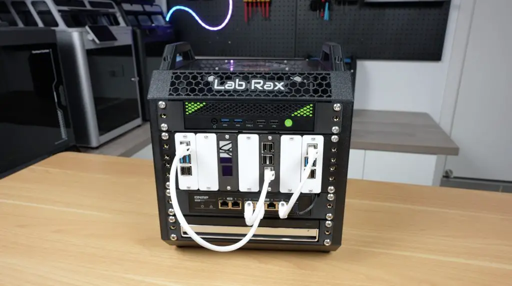
If you’ve been following my projects, you’ll probably remember my Lab Rax system, a 10-inch modular and 3D printable rack I designed to make it affordable and flexible to build your own homelab.
Today I’ve got something new to add to it, a set of 3D printable shelves for drives and SBCs (Single Board Computers), designed specifically to turn your Lab Rax homelab into a compact and customizable NAS (Network Attached Storage).
These shelves can be used as part of a larger Lab Rax setup or on their own as a dedicated NAS. In this post, I’ll walk you through the four new shelf designs, explain how to assemble them, and then show you two example NAS builds, one with a Raspberry Pi 5 and another with a Zimaboard 2.
Here’s my video of the project, read on for the write-up;
Some of the above parts are affiliate links. By purchasing products through the above links, you’ll be supporting this channel, at no additional cost to you.
A Quick Recap: The Lab Rax System
The Lab Rax framework is 10 inches wide, making it a lot smaller than a standard 19-inch rack. But it still uses the same unit height (U) spacing and hole patterns as a 19-inch rack, so you can mix and match modules from other 10-inch rack systems.
The goal is flexibility, start with a small setup and then expand as you need more shelves, drives, computers, or networking gear.
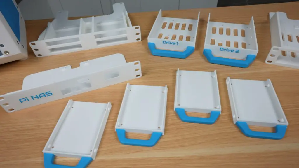
The New 3D Printable NAS Shelves
I’ve designed four new 1U shelves, two for holding drives and two for housing SBCs to run the NAS. Let’s go through them one by one.
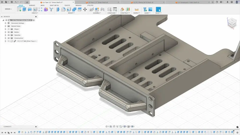
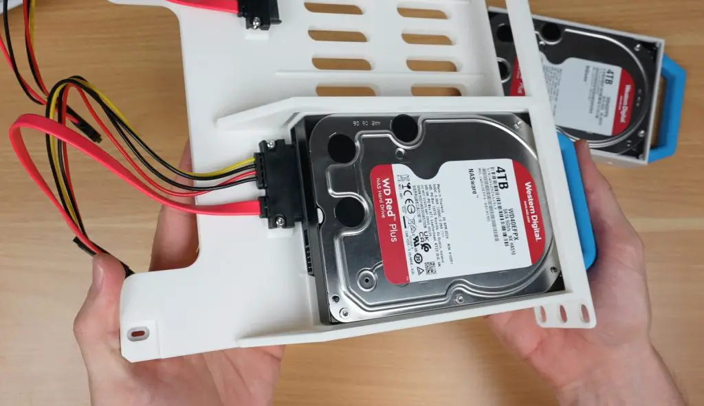
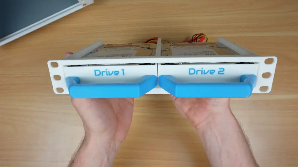
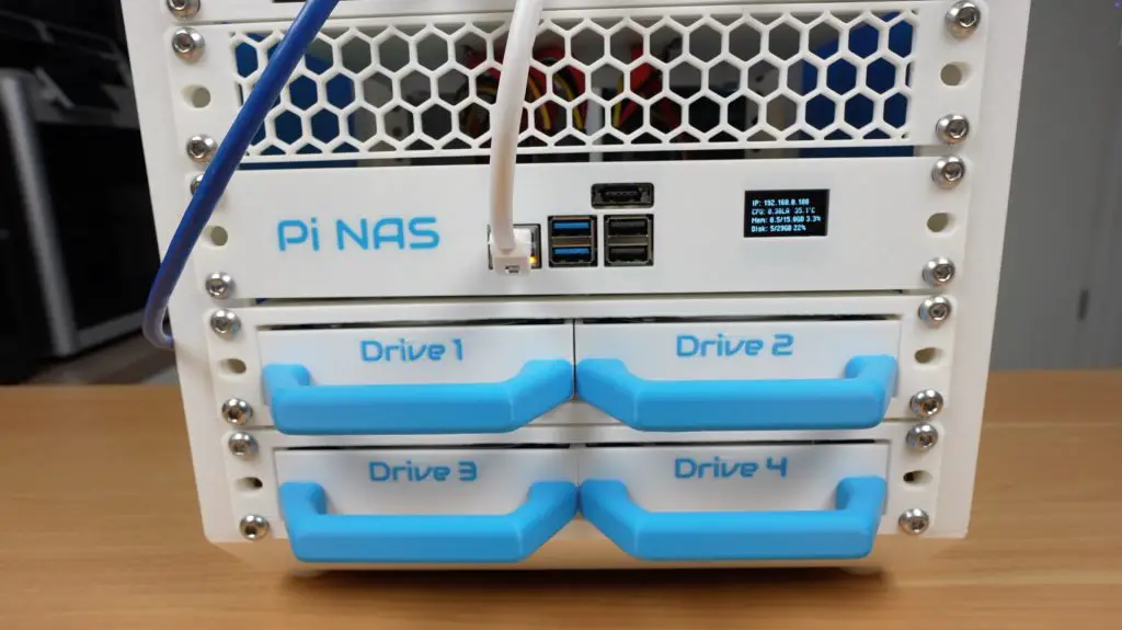
1. Dual 3.5″ Drive Shelf (1U)
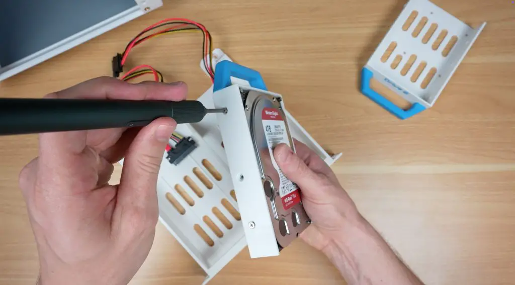
This shelf holds two 3.5-inch drives, each mounted in a pull-out tray for easy swapping. The trays slide into rails built into the shelf body, and each drive is secured with M3 drive screws through holes in the sides of the tray.
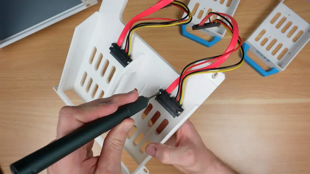
At the back of each bay, there’s a mounting point for a SATA data and power cable.
Although designed for 3.5″ drives, the bays are dual-purpose, so you can mount 2.5″ drives into the same trays using the appropriate screw holes.
For airflow, the front and sides of the shelf are vented. I recommend leaving at least 1U of space for cooling, or installing a 120mm fan on the sides of the rack if you’re stacking multiple of these with spinning hard drives.
Print the main shelf body and the drive trays separately. I’ve prepared print profiles on Makerworld for Bambulab printers.
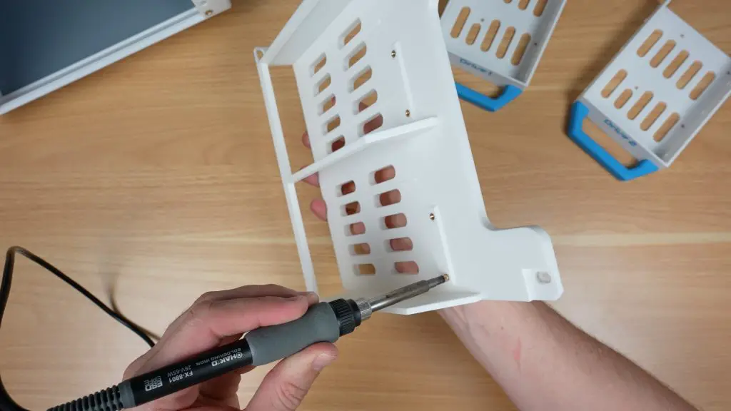
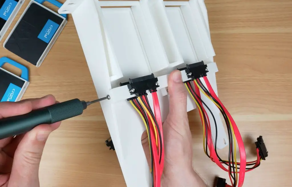
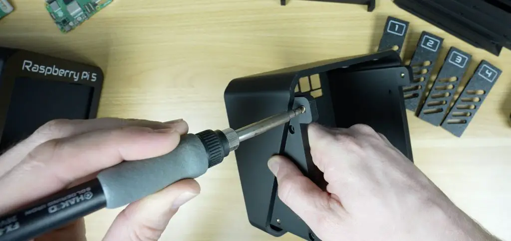
To mount the SATA cable connectors;
Use a soldering iron to add M3 threaded brass inserts into the prepared holes, two per connector.
Secure each connector using two M3x8mm button head screws.
You’ll need M3 drive screws to secure the drives to the trays.
Once the drives are fixed in place, slide the trays into the shelf until they click or stop against the rear cable mounts.
If they don’t click into place easily, loosen the M3 screws on the connector slide the drive in and then tighten them with the drive in place to correct the alignment.
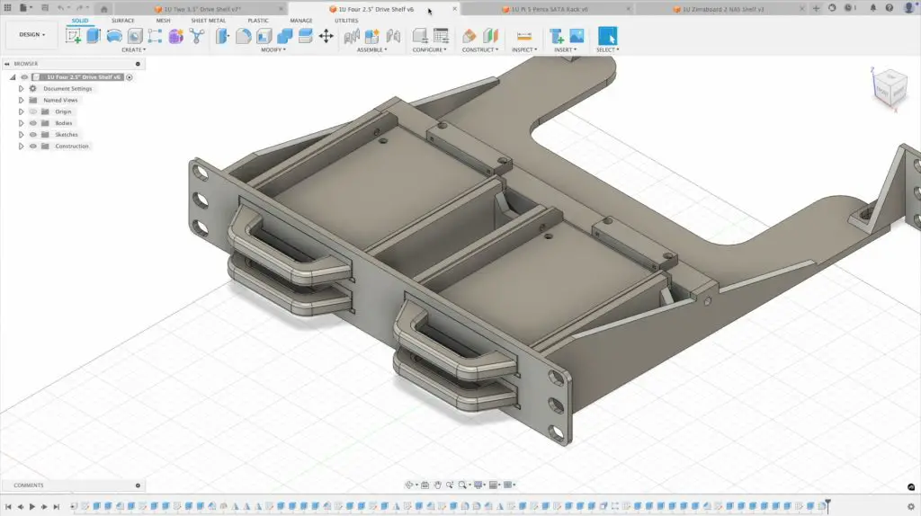
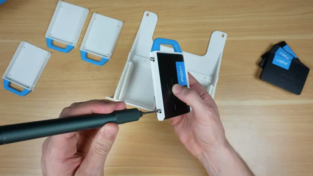
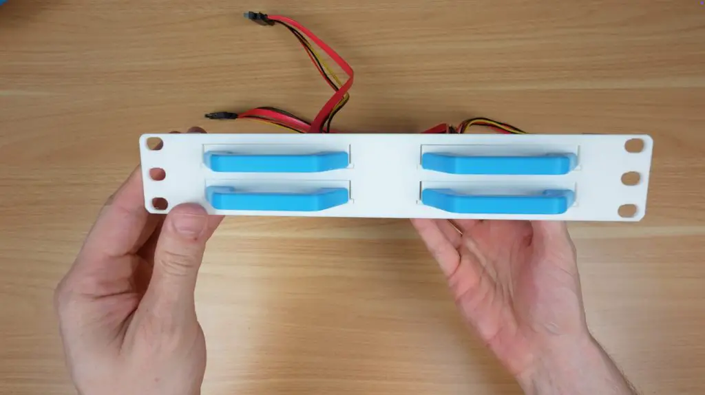
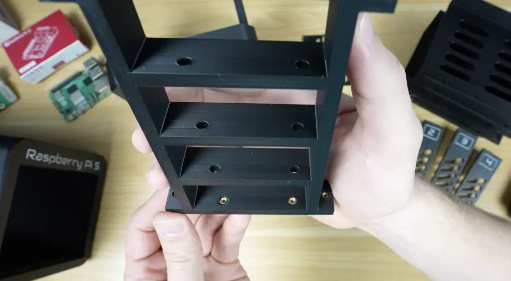
2. Quad 2.5″ Drive Shelf (1U)
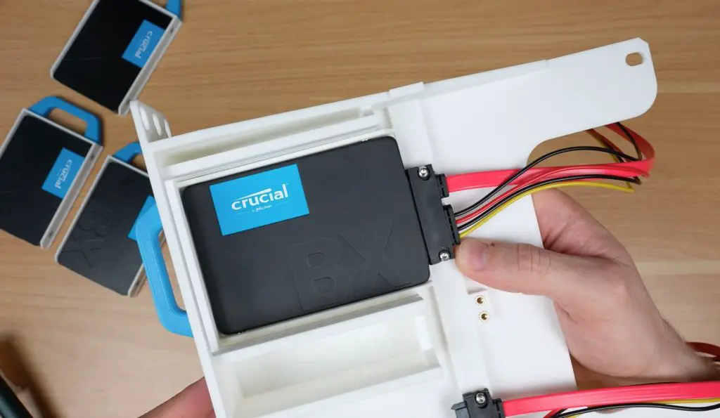
If you’re using SSDs or smaller mechanical drives, this shelf is ideal. It holds four 2.5-inch drives, again using pull-out trays with the same SATA cables as the 3.5″ version.
Each drive is secured to the tray with M3 drive screws into the sides of the drive.
Because 2.5″ drives run cooler and lighter, this shelf is especially well-suited for higher density SSD setups.
Print the main shelf body and the drive trays separately. I’ve prepared print profiles on Makerworld for Bambulab printers.
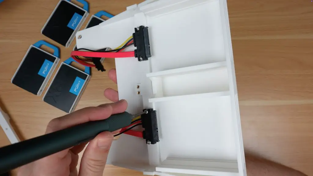
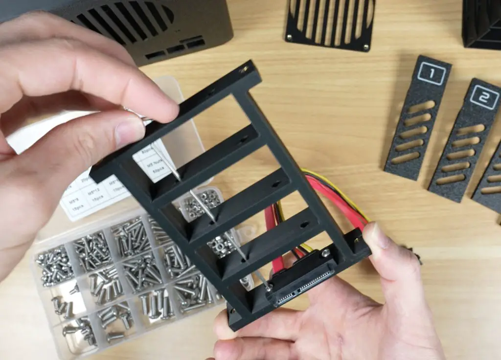
To mount the SATA cable connectors;
Use a soldering iron to add M3 threaded brass inserts into the prepared holes, two per connector in both the shelf and the SATA connector bracket (for the top two drives).
Add another four threaded brass inserts for the SATA connector bracket. One in each end of the bracket and two in the centre of the shelf for the bracket to be screwed onto.
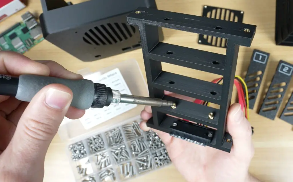
Secure the two bottom connectors using two M3x8mm button head screws each.
Secure the two top connectors to the bracket using two M3x8mm button head screws each.
Screw the SATA connector bracket to the shelf using four M3x8mm button head screws, one on each end and two in the middle.
You’ll need M3 drive screws to secure the drives to the trays.
Once the drives are fixed in place, slide the trays into the shelf until they click or stop against the rear cable mounts.
If they don’t click into place easily, loosen the M3 screws on the connector slide the drive in and then tighten them with the drive in place to correct the alignment.
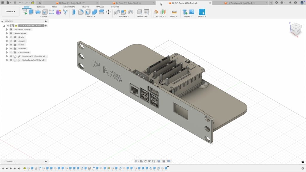
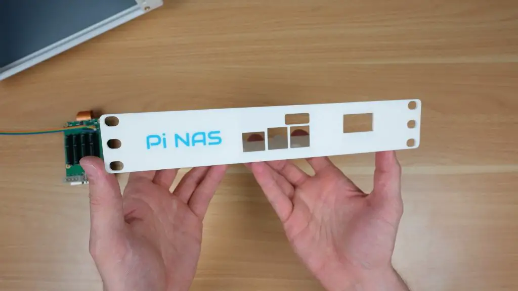
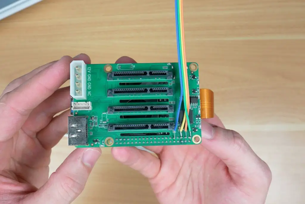
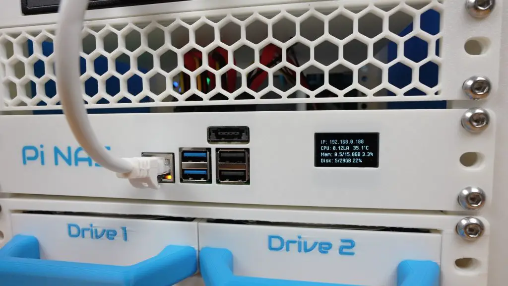
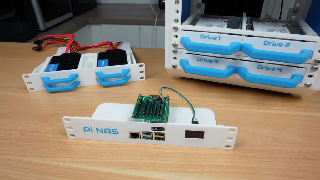
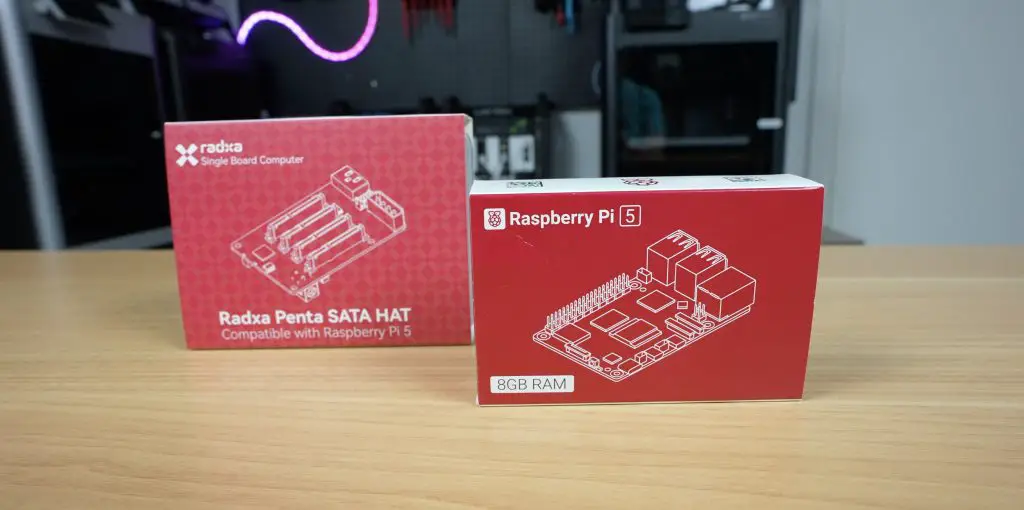
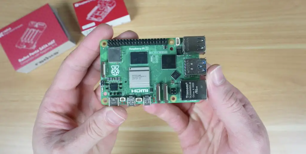
3. Raspberry Pi 5 NAS Shelf (1U)
This shelf is designed to house a Raspberry Pi 5 alongside the Radxa Penta SATA HAT, which provides up to five SATA connections, four standard SATA ports and one eSATA port.
The Pi mounts into 3D printed standoffs on the shelf base.
The SATA HAT sits directly on top of the Pi, with the four SATA ports facing upward and the eSATA port facing the front of the rack.
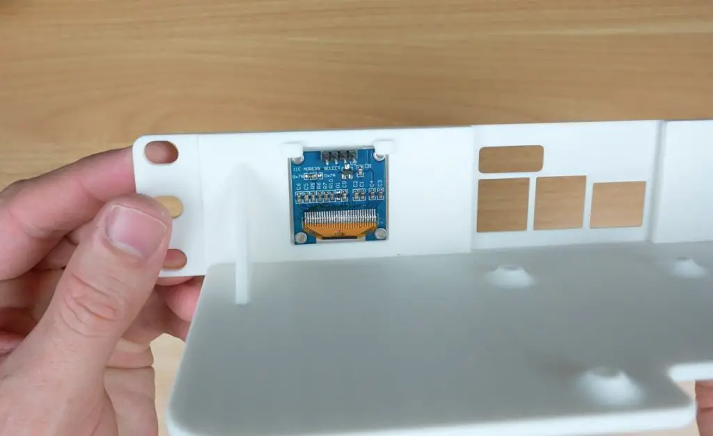
I also included a space for a small I2C OLED display so you can install my OLED display stats script to monitor system stats.
This compact design allows you to run a full NAS controller with stats feedback in just one rack unit.
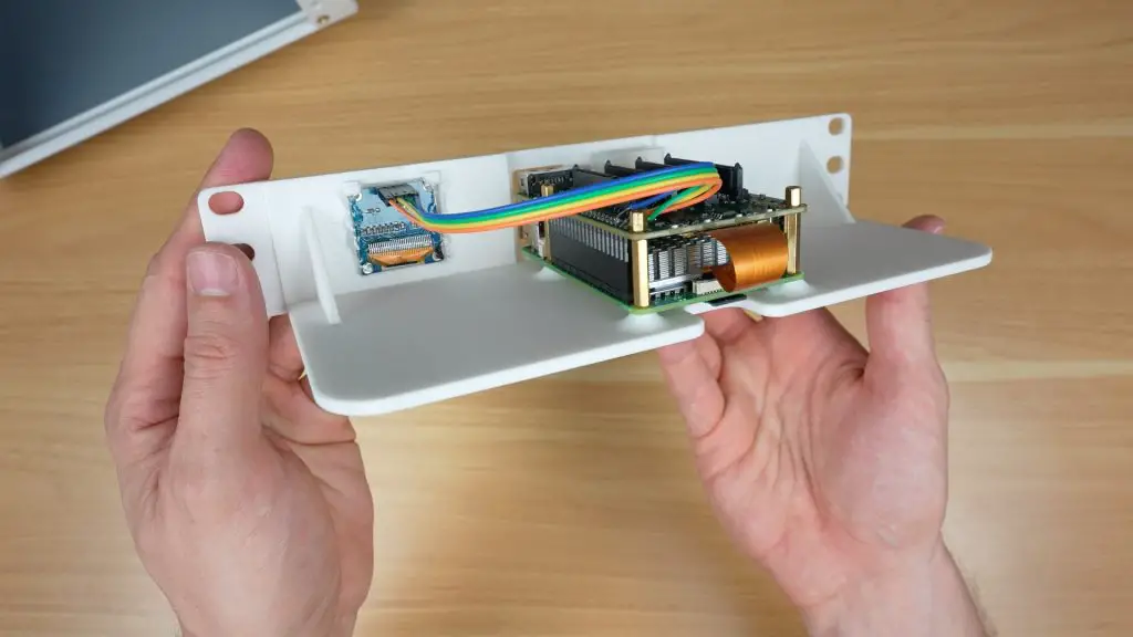
Start by installing the Pi on the shelf using the 18mm brass standoffs supplied with the Radxa Penta SATA hat and nuts through the pockets in the bottom of the shelf.
Plug the Penta SATA hat into the Pi’s GPIO pins and connect the PCIe ribbon cable. Secure it with brass standoffs on top of the hat.
Install the OLED display in the holder. It is held in place at the top using the 3D printed clips and you can secure the bottom with a few drops of superglue or hot glue.
A 4 wire ribbon cables connects the display to the GPIO pins. You’ll need to connect GND, 3.3V, SCL and SDA. I’ve soldered the ends to the tops of the GPIO pins on the Radxa hat.
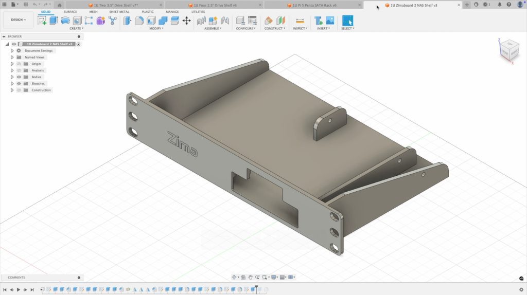
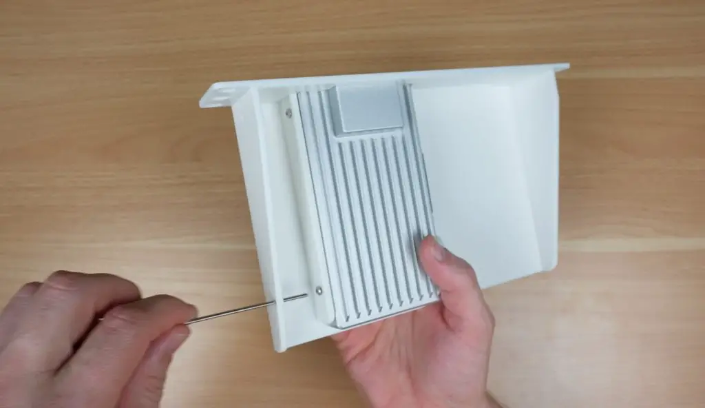
4. Zimaboard 2 NAS Shelf (1U)
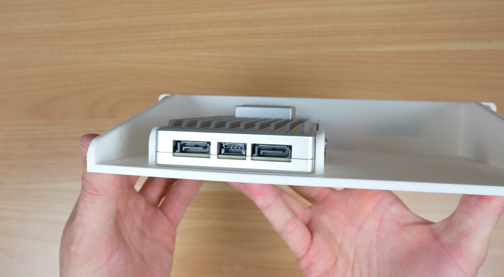
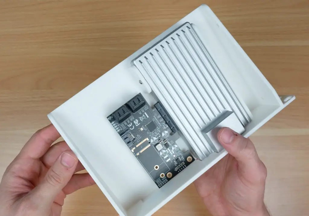
The final shelf is built around the Zimaboard 2. I made this one up because the Zimaboard already includes two SATA ports on the back panel and has a PCIe port for expansion, so its a more versatile option for building a multi-bay NAS.
The Zimaboard mounts neatly into the tray, with easy access to the rear I/O.
The design also allows space for a PCIe SATA expansion card. The card I’ve used gives you five additional SATA ports for a total of seven. This makes it a much more expandable option if you’re planning a larger NAS.
The Zimaboard 2 slides into place and is secured by three M3x8mm button head screws through the sides. These are easily installed using a hex key through the holes in the side walls of the shelf.
A PCIe SATA card can then be installed in the slot alongside it.
Example NAS Builds
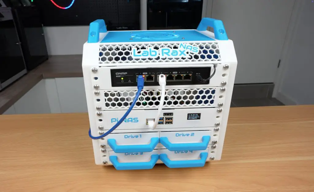
Now let’s look at two example builds using these shelves, both built into a standard 5U Lab Rax case. The Pi build only uses 4U, leaving one spare unit for future expansion.
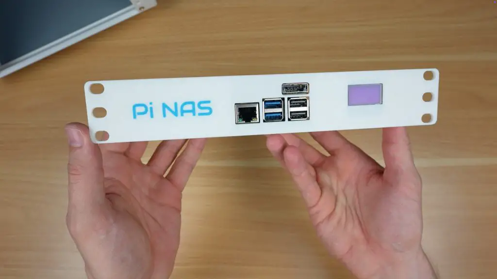
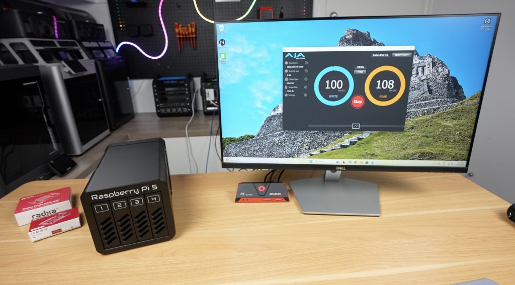
Build 1: Raspberry Pi 5 NAS
Top unit: QNAP network switch.
Second unit: Ventilation panel to allow space for the SATA cables (and can be used for future expansion)
Third unit: Raspberry Pi 5 shelf with Radxa Penta SATA HAT and OLED display.
Fourth and fifth units: Two dual 3.5″ drive shelves (4 drives total).
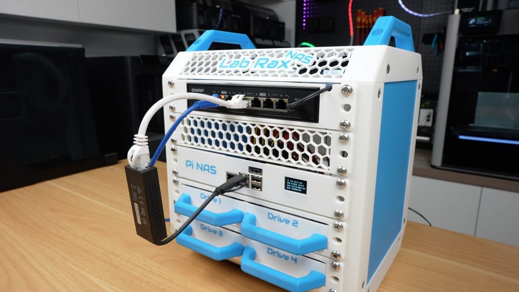
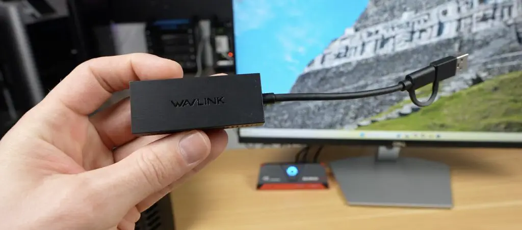
This switch is a bit overkill for the Pi’s gigabit ethernet port but I’m going to be using it wit a 2.5G network adaptor plugged into one of the Pi’s USB 3 ports. This gives significantly faster transfer speeds compared to the Pi’s built-in gigabit Ethernet.
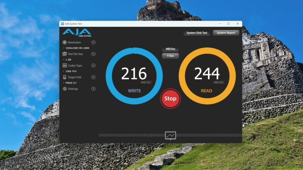
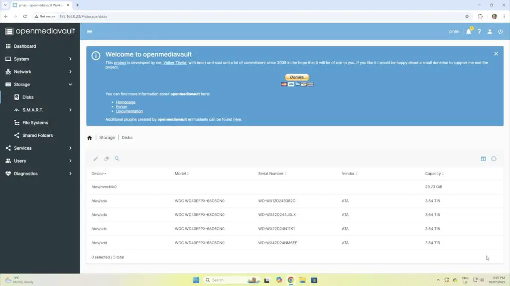
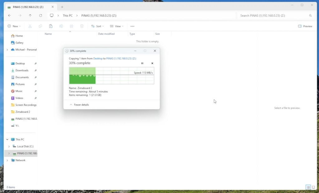
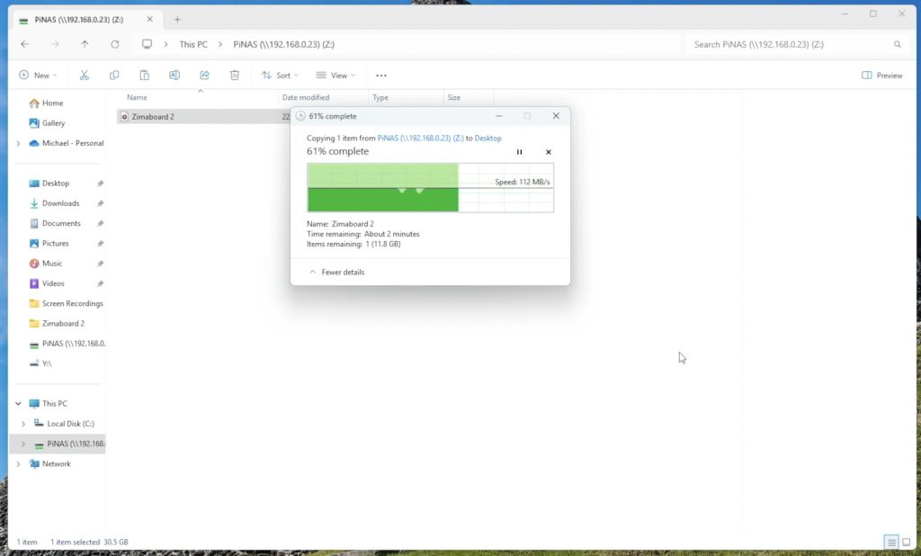
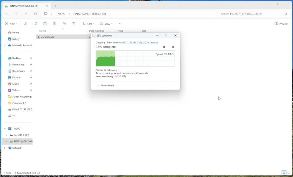
Running OpenMediaVault (OMV) on the Pi 5 with the drives set up in a RAID 5 pool, I achieved:
Write speeds: ~215 MB/s
Read speeds: ~240 MB/s
The main limitation here is expansion, with only one PCIe lane on the Pi 5, there are limited options for going beyond 5 drives.
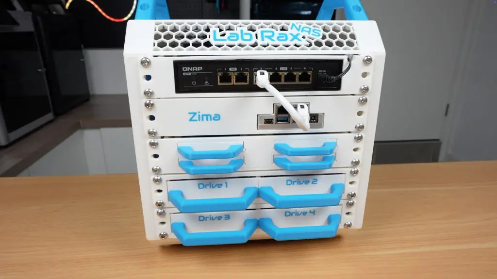
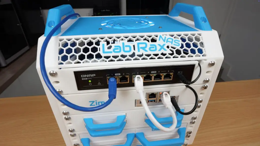
Build 2: Zimaboard 2 NAS
Top unit: QNAP network switch.
Second unit: Zimaboard 2 shelf with space for PCIe SATA expansion.
Third unit: Quad 2.5″ drive shelf (4 SSDs).
Fourth and fifth units: Two dual 3.5″ drive shelves (4 drives total).
This setup offers much greater expandability thanks to the PCIe slot. With the PCIe card that I used, you can connect up to seven drives in total, but these cards are also available with higher port counts.
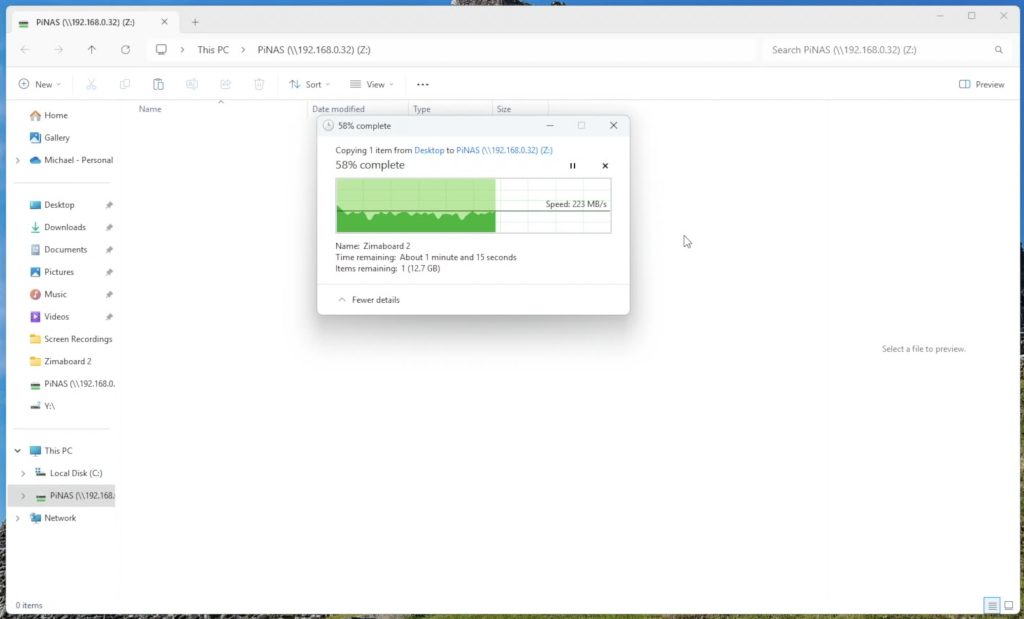
The Zimaboard runs ZimaOS, a clean and user-friendly NAS operating system that makes pooling drives and managing shares very straightforward.
In testing, I saw slightly higher performance than the Pi build:
Write speeds: ~230 MB/s
Read speeds: ~260 MB/s
Better handling of multiple simultaneous transfers and generally performs better due to the more power N150 CPU.
Dual network ports for redundancy or link aggregation.
Final Thoughts
These new shelves transform the Lab Rax system from a general-purpose rack into a capable and modular NAS framework.
If you want something small and affordable, the Raspberry Pi 5 build is an excellent option.
If you need more power and expandability, the Zimaboard 2 build is the better choice.
Because the shelves are 3D printable, easy to assemble, and designed to fit common print bed sizes, anyone can replicate these builds at home. I’m really happy with how they turned out and I’ll be adding more modules in the future as I keep developing the Lab Rax ecosystem.
Which one would you build, the Pi 5 NAS or the Zimaboard 2 NAS? Let me know in the comments below!
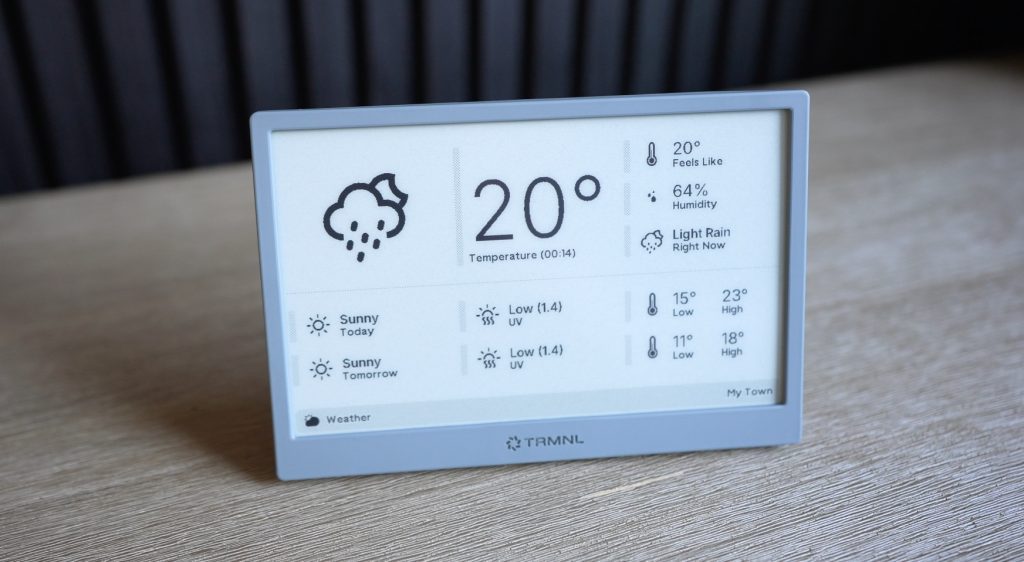
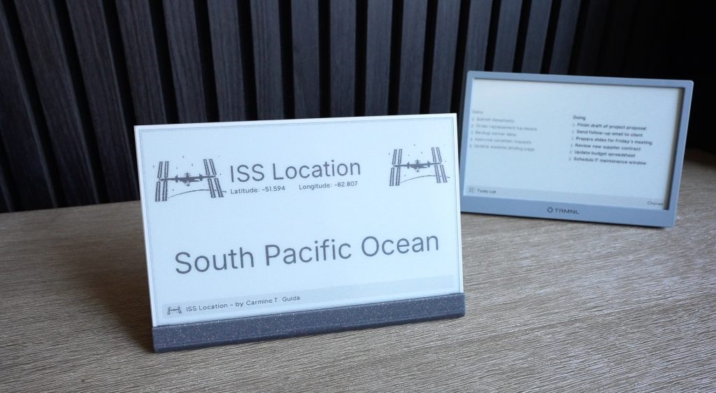
Imagine a little screen on your desk, wall or even fridge, quietly updating you with your calendar, to-do list, or the weather without the distractions of a phone or computer.
That’s what TRMNL is, a sleek, open-source, battery-powered e-ink display that’s built to be simple, low power and easy to use.
Today I’ll show you what the ready-made TRMNL can do and then we’ll go a step further and actually build one ourselves, from scratch, to see if it’s worth making your own or buying their version.
Here’s my video review and build, read on for my write-up;
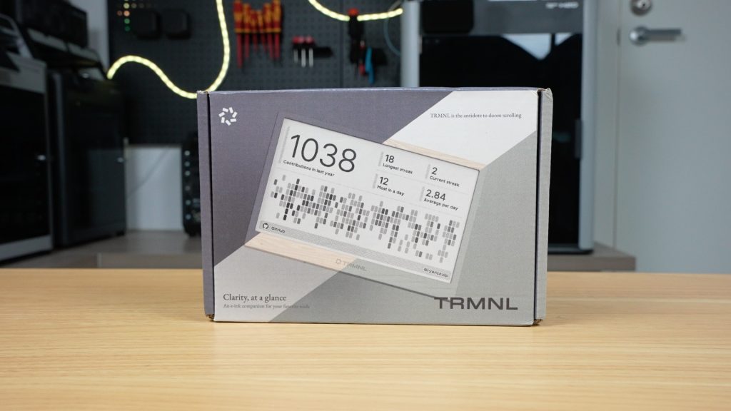
This is the TRMNL package that you can order directly from their website from $139. They also have a few different finishes and some add-ons like a battery upgrade and developer license to create your own plugins.
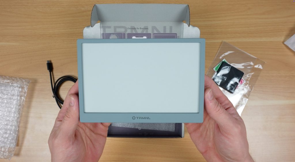
I got the Clarity Kit which includes the developer license, a USB-C charging cable, a screen protector, and then the terminal itself, which has the upgraded 2500mAh battery.
This is the grey version and it comes in a total of six different colours.
Design and Features
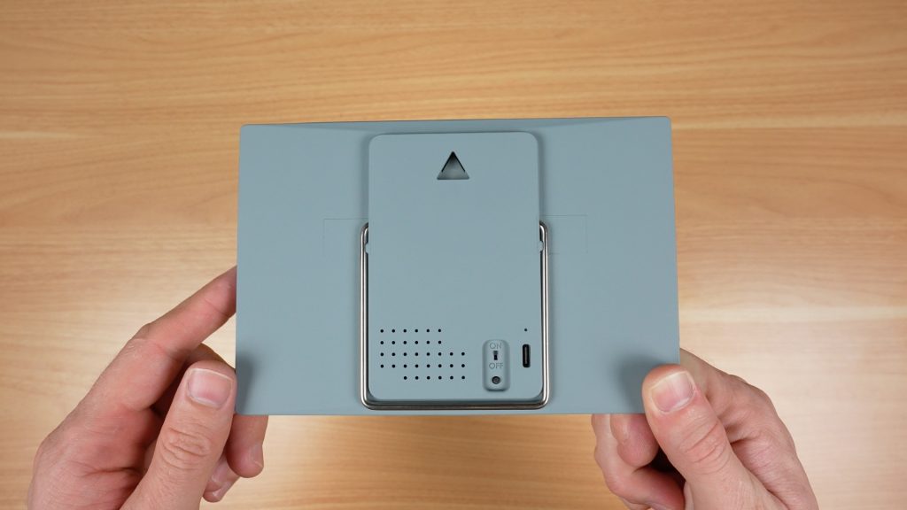
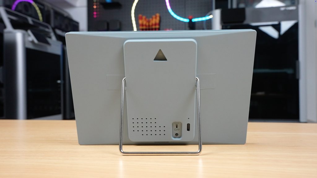
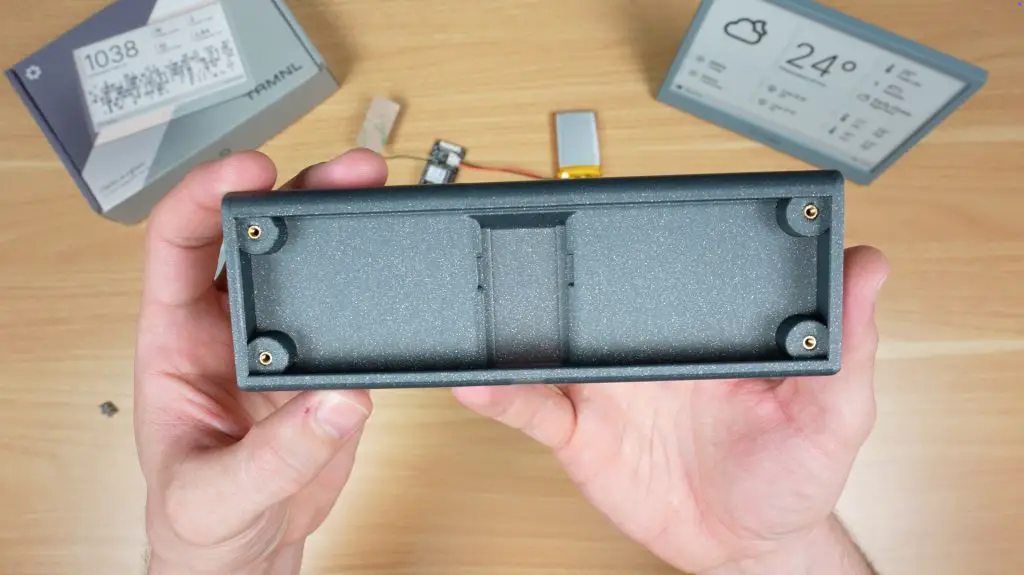
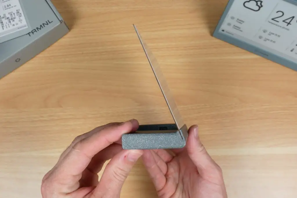
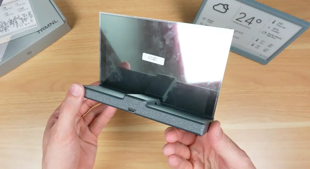
On the front we’ve got the 7.5” e-ink display, and on the back is the power switch, a button to refresh the screen, and a USB-C port for charging.
It’s also got two mounting options:
A hanging point for a nail or screw
A flip-out metal stand
I kinda wish it had a magnetic option as well to stick it onto a fridge or filing cabinet.
The device is preassembled and ready to go, with their software already installed.
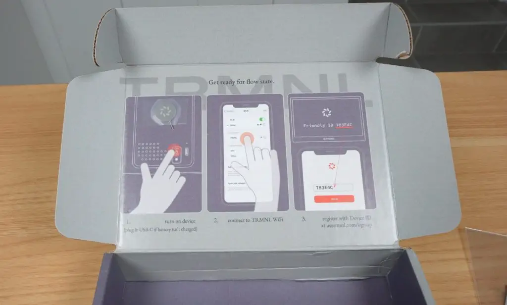
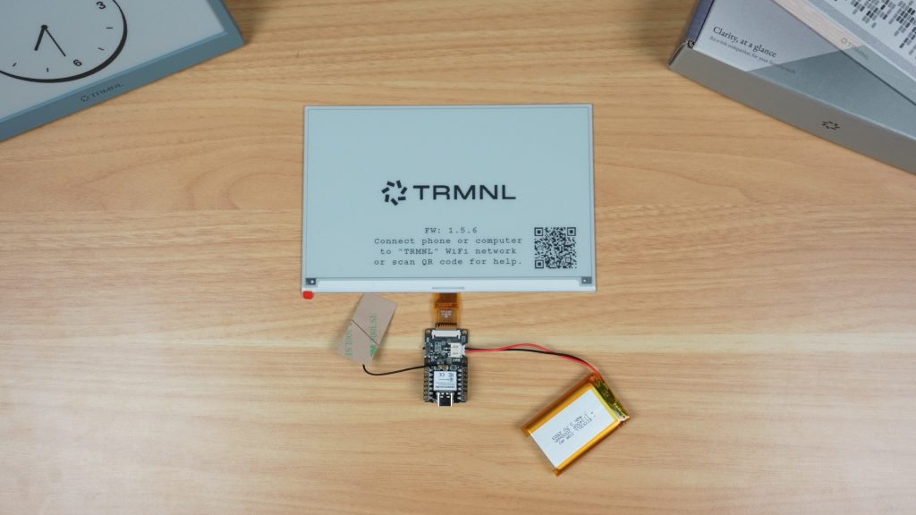
Setup Process
I found the setup process really easy to work through. You essentially connect to TRMNL’s WiFi hotspot to tell it how to connect to your WiFi network and then link it to your account using a device ID.
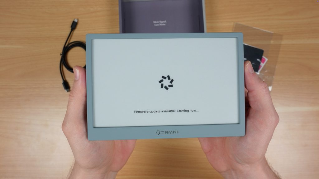
After linking to your account, it automatically updates the firmware and the rest is then managed through their website.
Battery Life
One of the best features of TRMNL is that because it’s got an e-ink display and a low power microcontroller, it doesn’t need to be permanently plugged in. The built-in battery will power it for up to 6 months between charges, depending on how often it is updating the display.
Being an e-ink display, it only requires power to change the image. Between updates the display is off and the microcontroller goes into a low power sleep mode.
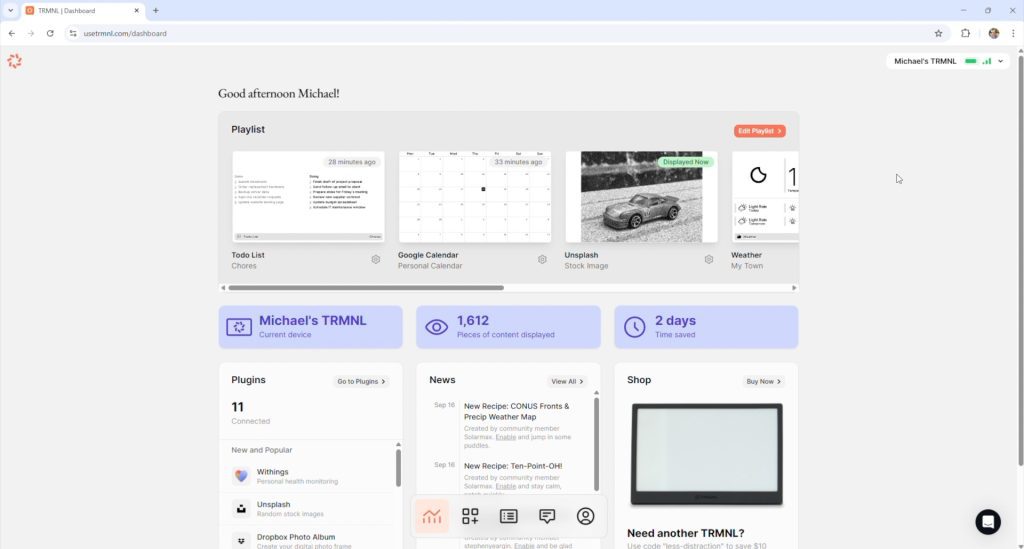
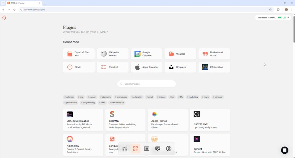
Software and Plugins
Their website is fairly easy to use once you get the hang of it, but it can be a bit confusing when you first open it up.
There are basically three components to what is displayed:
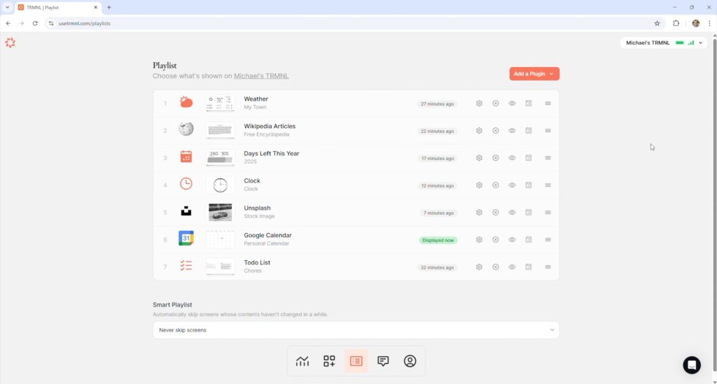
Playlists
Plugins
Recipes
Plugins and Recipes are essentially the apps that provide the content to be displayed. Plugins are developed by TRMNL themselves and Recipes are community-developed.
You then load these into a Playlist which allows you to cycle through them so that you’re not limited to just running one app at a time.
There are also a few other options, like having up to four plugins or recipes displayed at once through one of eight available layouts, so you can really get quite a lot of information onto it.
Limitations
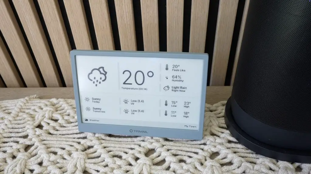
This is not an LCD or OLED display, so you’re not getting an HD-quality image. The highest refresh rate that you can set is once every 5 minutes, but that’s the point.
It’s intended to be a minimalist display for data that doesn’t change very quickly or often, and that will run for months between charges.
You can even set it to only update once every hour and to enable sleep mode during times when you’re not around it anyway, and that’ll extend battery life to over 10 months.
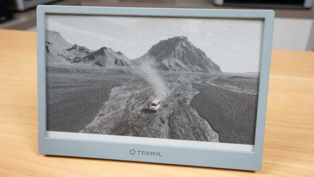
You can use it to display images, and there are a couple of plugins for photos which get the job done, but it’s not what this screen is intended for. The rendered image is quite grainy. It’s far better suited to displaying sharp text and simple graphics.
At the time of making this post, there are over 500 plugins and recipes available for TRMNL, so you should easily be able to tailor it to your needs.
Building A DIY Version
Now let’s move on to the DIY version.
Since the team behind TRMNL have made it completely open source, they’ve also published everything you need to build your own version. You can even register DIY devices on their server to use their web platform too.
They say that their retail price is often cheaper than building your own, and that may be true depending on where you get your components. But I found it to be a tiny bit cheaper.
DIY Component Costs
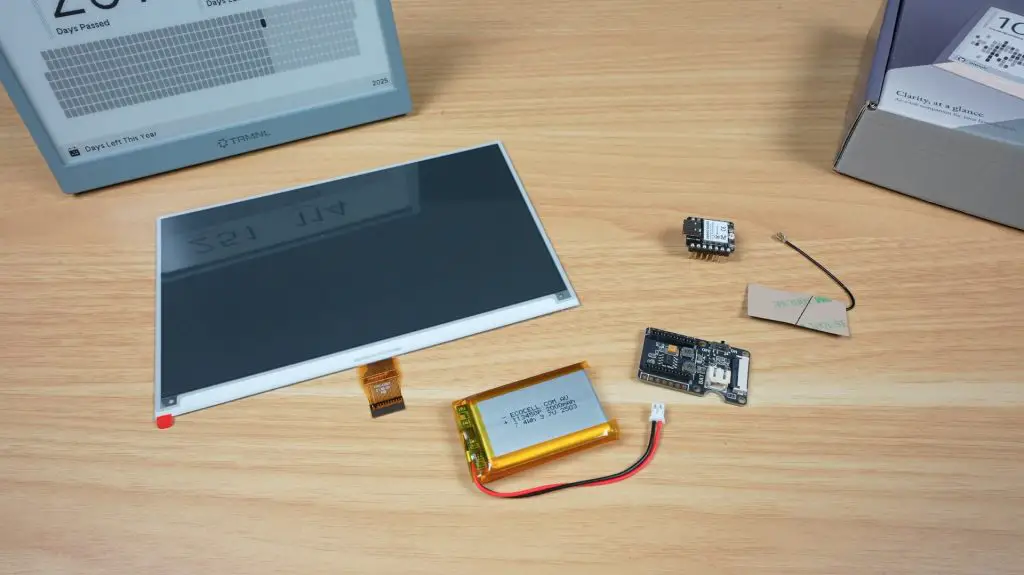
Here’s what I used:
7.5″ e-ink display – $35
ESP32 with antenna – $6
E-ink Display breakout board with built-in battery charger – $5
2000mAh battery – $10
That’s just $55 for the components, or $70 including shipping.
This is quite a bit cheaper than TRMNL’s $139 price tag. But that’s before adding their $50 one-time device fee (BYOD License) to use their server, and without an enclosure, which I’m going to design and 3D print myself.
So all up, I think it’s fair to say that you’ll be in for a similar price either way.
Server Options
You also don’t have to pay the $50 BYOD License fee to use their server. You can host your own server privately if you’d like to. This will do away with the device fee as well as keep all of your data in-house.
Personally, I like the ease of use of their website and I’d rather pay a one-off fee than have to pay a monthly subscription, so I’m glad they’ve gone with this model.
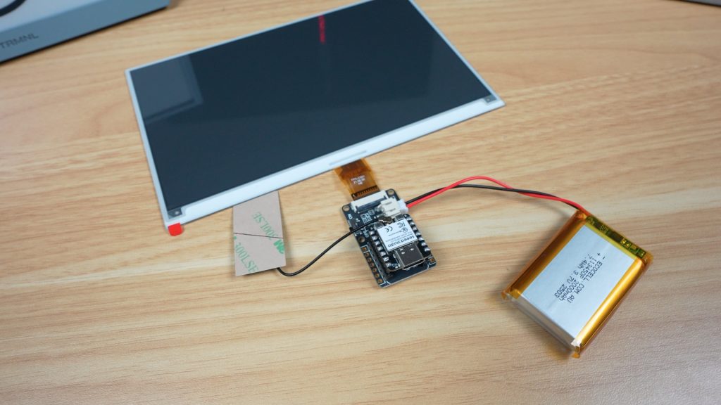
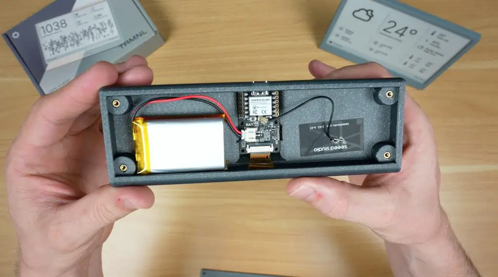
The DIY TRMNL Build
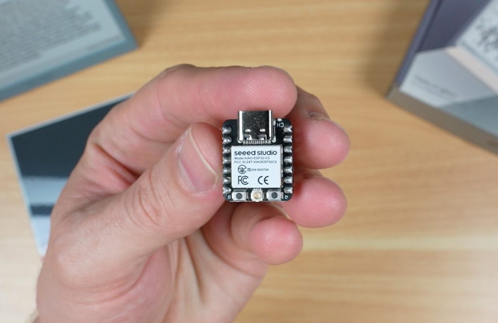
The heart of the DIY TRMNL is the little ESP32 module. This is a 32-bit RISC-V chip that operates at up to 160MHz.
Its real strength is low power consumption, it can use as little as 44 microamps in deep sleep mode, which makes it perfect for this type of battery-powered project. It’s also got built-in 2.4GHz WiFi and Bluetooth 5.
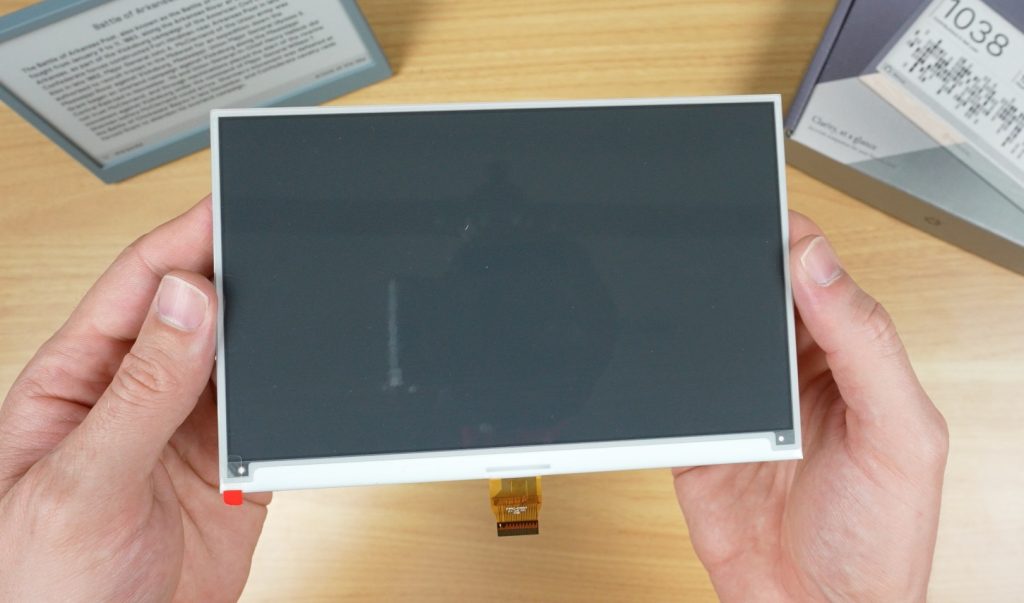
The 7.5″ display that we’re pairing it with has a resolution of 800×480 and it takes around 3.5 seconds for a full refresh of a single frame. So it’s not winning any awards for performance, but like the ESP32 it’s really good on power consumption. It uses just 8 milliamps during a refresh and doesn’t need any power between refreshes to maintain what is displayed.
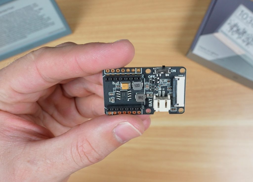
To connect these together, as well as use and charge the battery, we’ve got an e-ink driver board.
This has:
A 24-pin FPC connector for the display
A socket for the ESP32
A charging circuit and port for the battery
A power switch on the side
Because of the components I’ve chosen, there isn’t a whole lot to build. All of the components easily plug into the driver board. Some versions of the ESP32 module may require you to solder the pins onto the module beforehand.
Flashing the Firmware
Next we need to flash TRMNL’s firmware onto it.
There are a couple of options for this depending on the hardware you’re using, and these vary in complexity, from using a simple web tool to having to build the firmware from source code.
Once that’s done, you follow a similar process as before to pair it to your account, and you can then start creating playlists.
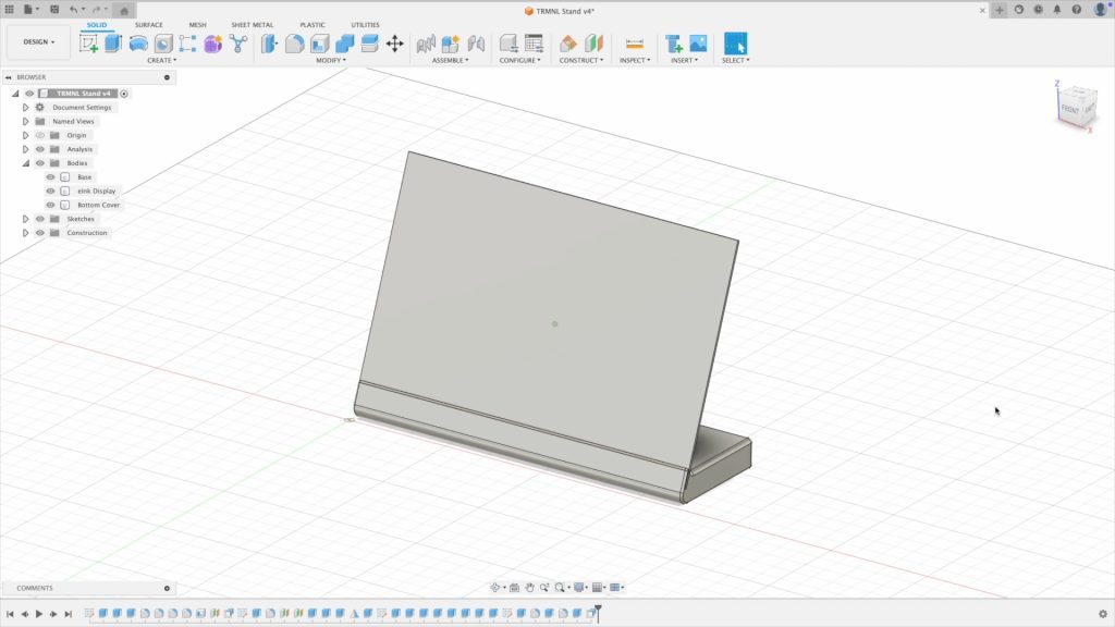
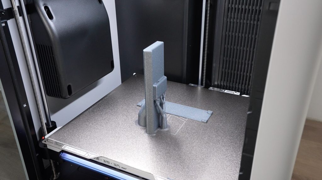
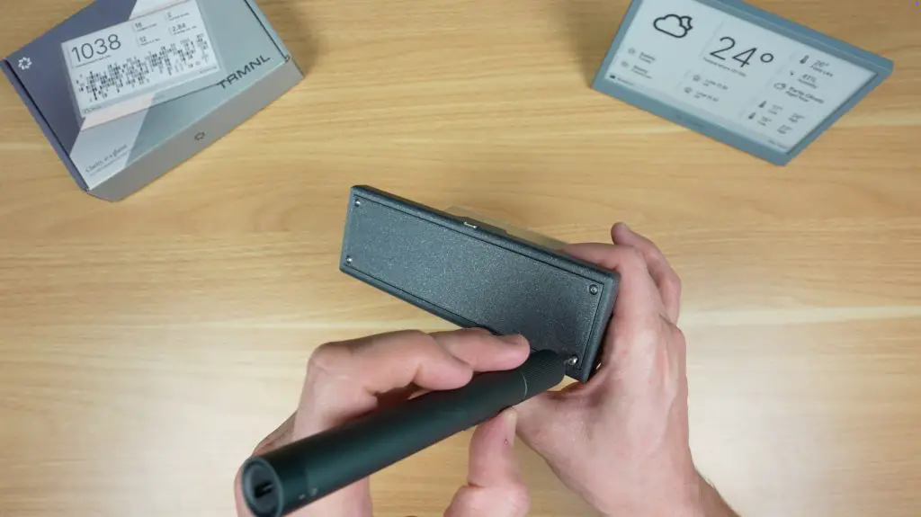
The Enclosure
I measured up the electronic components and designed a simple 3D-printable enclosure for them.
I wanted to make something a little different to the original TRMNL housing, so I went with this design which looks like it’s holding the ePaper display like a sheet of paper or card, really highlighting how thin it is while also sticking with the minimalistic theme. The electronics are then all stored in the base.
To finish it off, we just need to install some brass inserts in the base for the M2.5 screws to screw into. We can then install the display, ESP32 and battery, stick the antenna to the inside of the enclosure and then close it up.
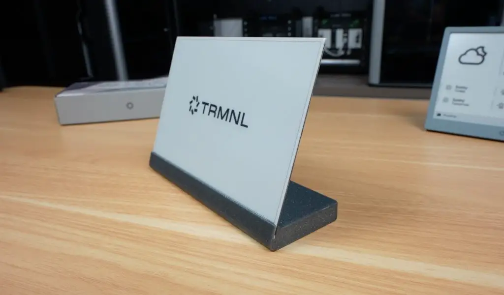
And we’ve now got a unique DIY TRMNL which provides similar functionality to the original. The only real missing feature is the button to refresh or change the display.
Final Thoughts on TRMNL
So that’s TRMNL. A minimalist smart display that you can either buy ready-to-go or build yourself.
Personally, I love that it strips away the noise and just gives you the info you actually want, when you need it.
If you’d like to get your own TRMNL, check out their website. I’ve also put my 3D printable design on Makerworld if you’d like to try build a DIY version.
I’d love to hear what you’d use TRMNL for and what you think of my DIY version, so let me know in the comments below.
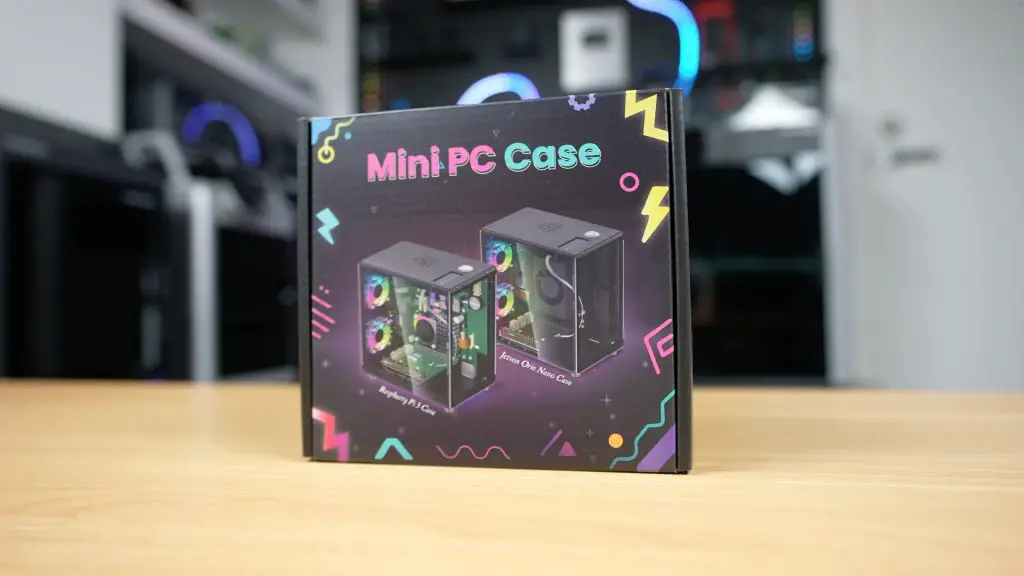
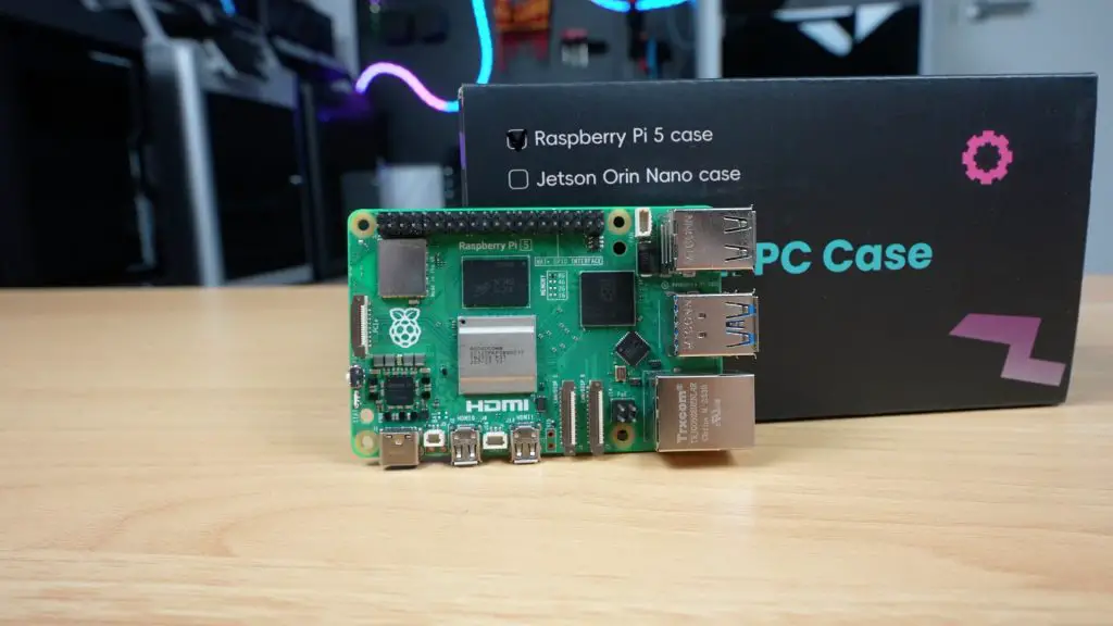
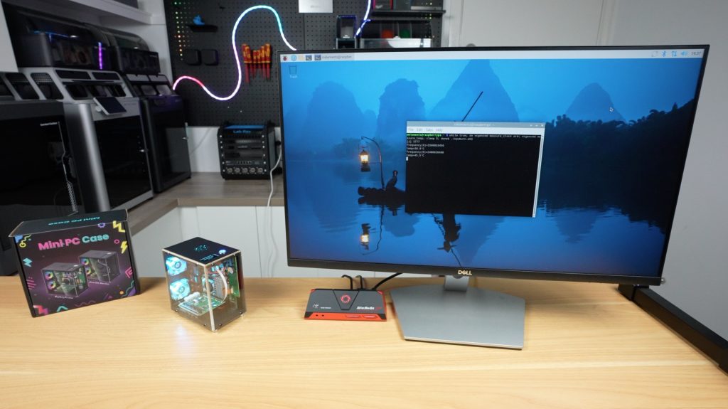
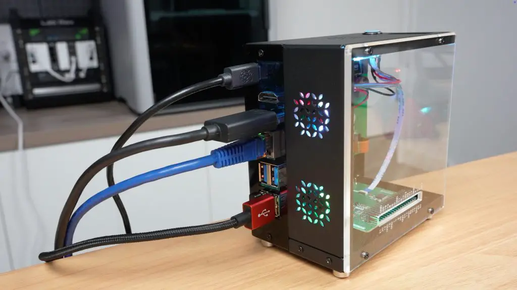
The Raspberry Pi 5 is powerful enough to be used as a mini desktop computer, and many people do, but finding the right enclosure for it can make all the difference. Today I’m looking at the new Mini PC style case from Elecrow, which aims to give your Pi the look and feel of a desktop computer without breaking the bank.
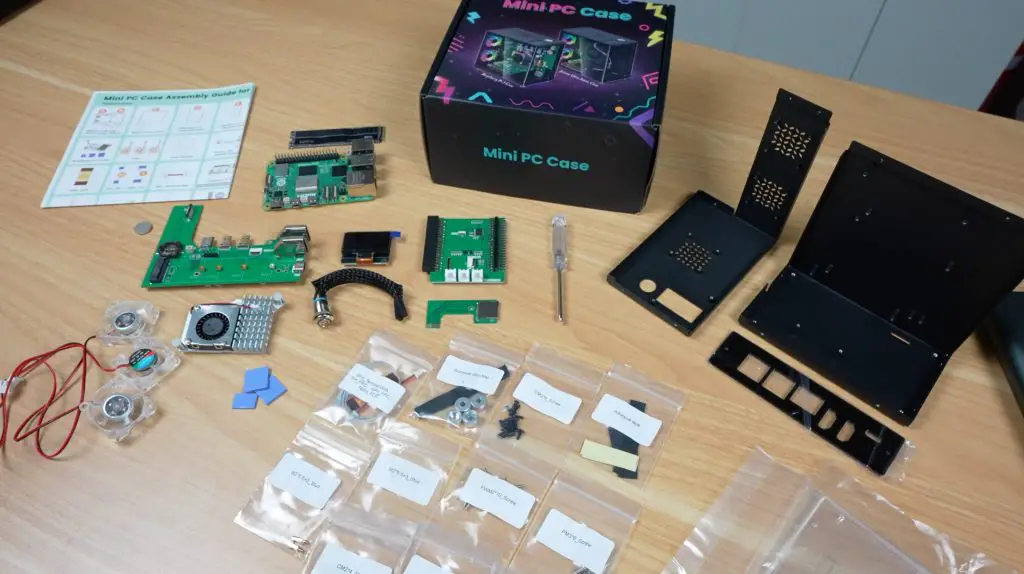
Like some of the other Raspberry Pi cases I’ve reviewed, this one comes with some cool features like a multi-fan cooling system, a port adapter that routes the Pi’s HDMI and power connections neatly to the back of the case, a 1.3″ OLED display, and an NVMe hat for connecting an SSD. What caught my attention, though, is the price. All of this comes in at just $40, which is significantly cheaper than most other cases with similar features.
So let’s find out whether it’s any good.
Here’s my video review of the case, read on for the write-up;
Where To Buy The Elecrow Mini PC Case For The Pi 5
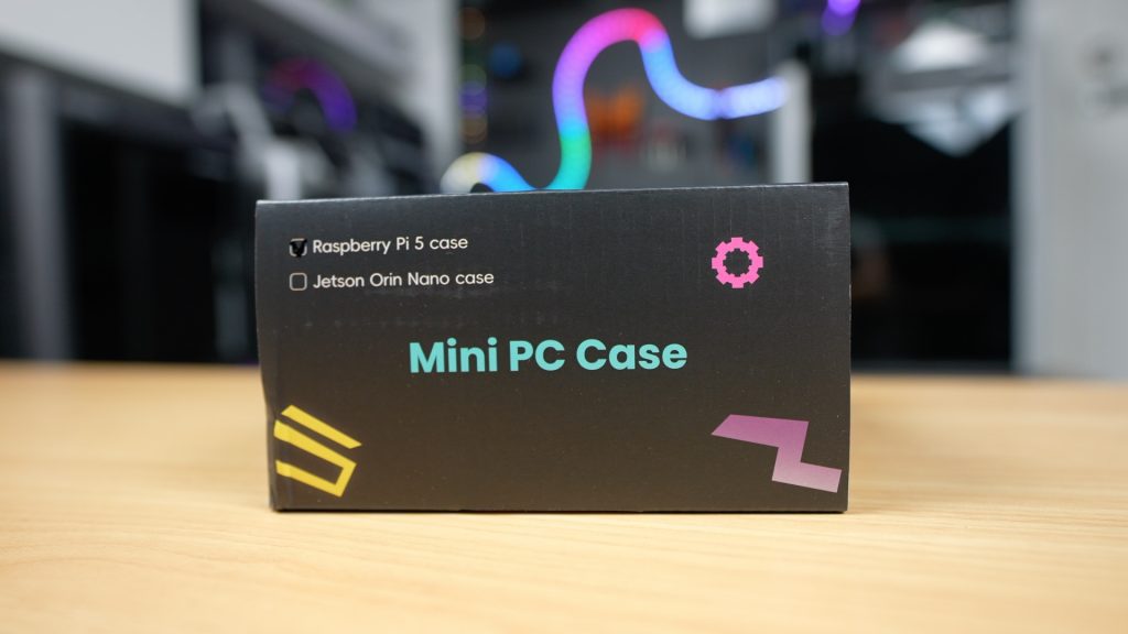
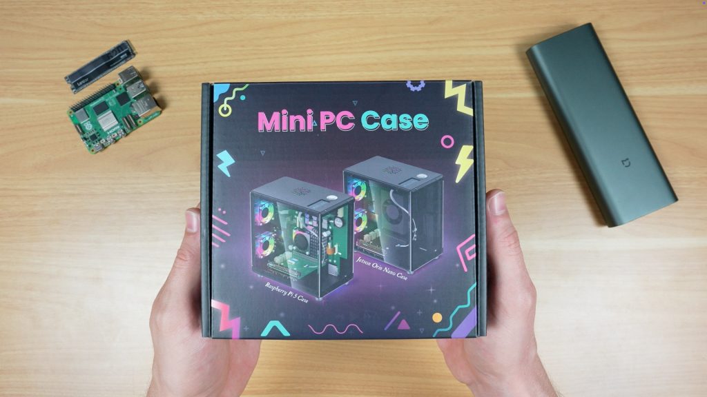
Everything is well packaged, with parts and screws are individually labelled to make assembly easy. For a case marketed for both the Raspberry Pi 5 and NVIDIA Jetson Orin Nano, it would have been nice if Elecrow included the small extra components required for both platforms rather than one or the other, but it’s still a solid set of inclusions for the price.
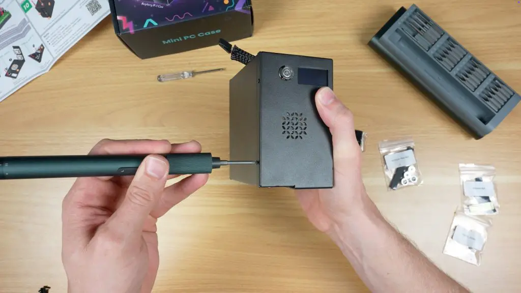
Assembling The Mini PC Case
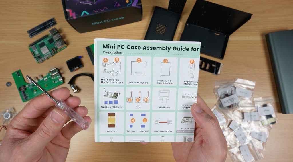
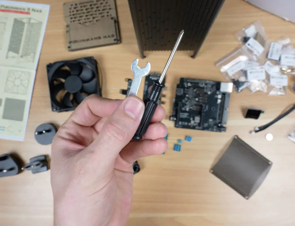
The case includes an illustrated instruction sheet and even a screwdriver, so assembly is straightforward.
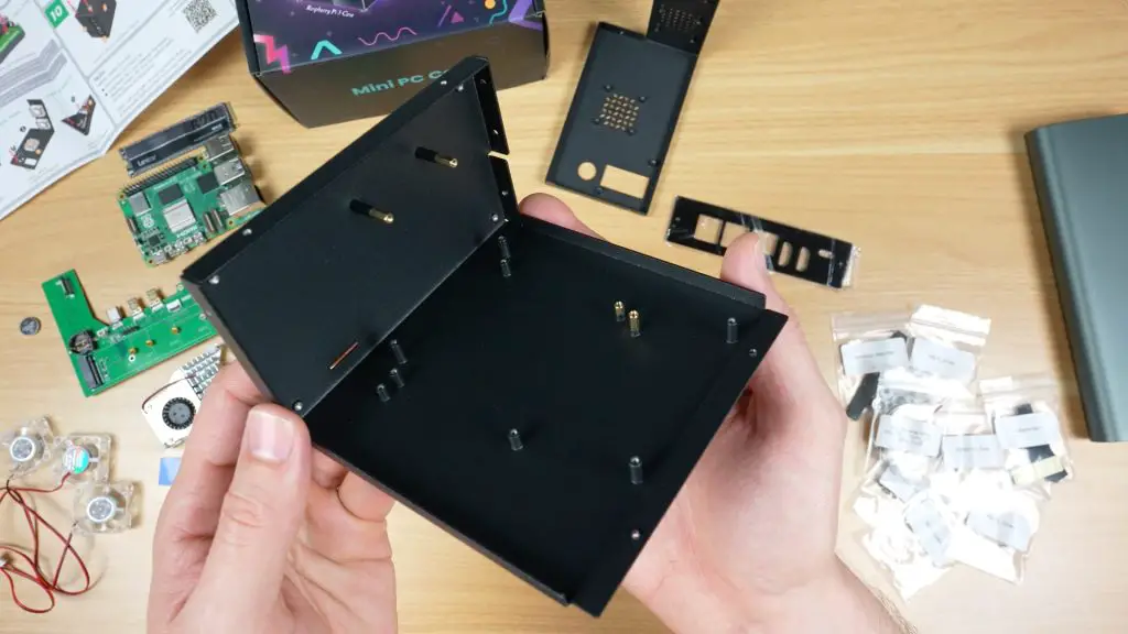
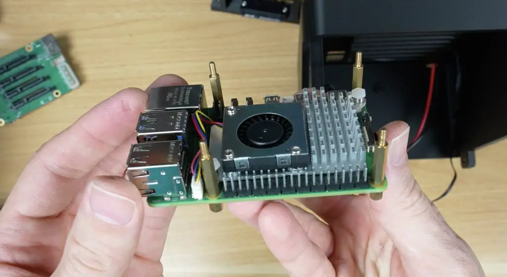
Brass standoffs are first installed onto one half of the enclosure.
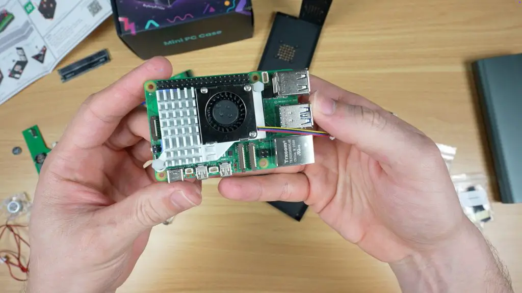
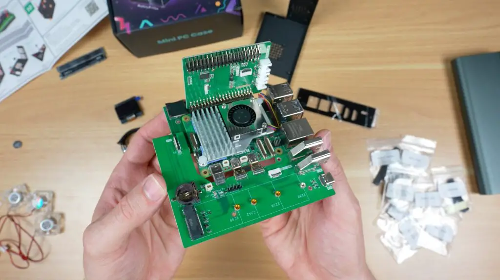
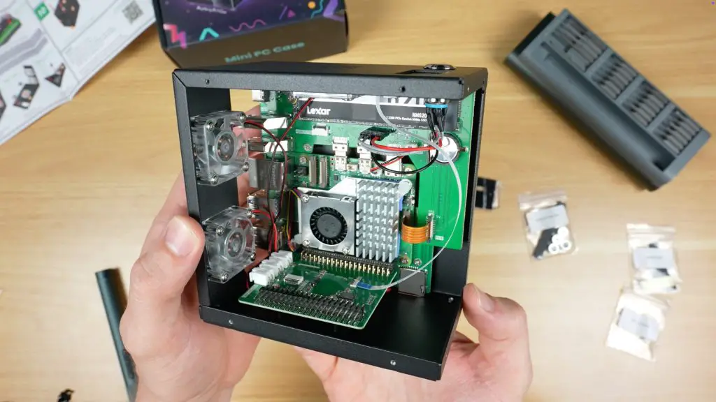
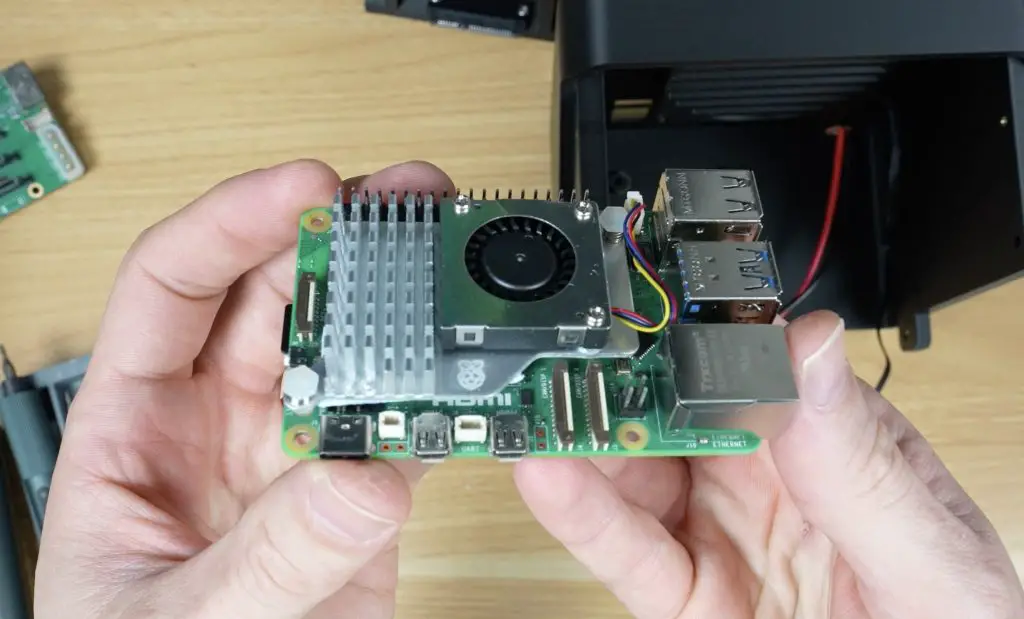
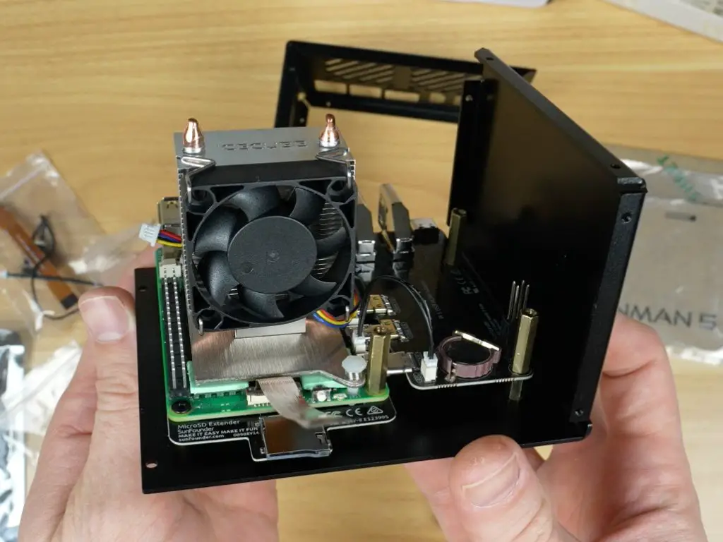
The cooling pads and heatsink are then mounted onto the Raspberry Pi 5’s heat producing components including the CPU, power circuitry, and WiFi chip.
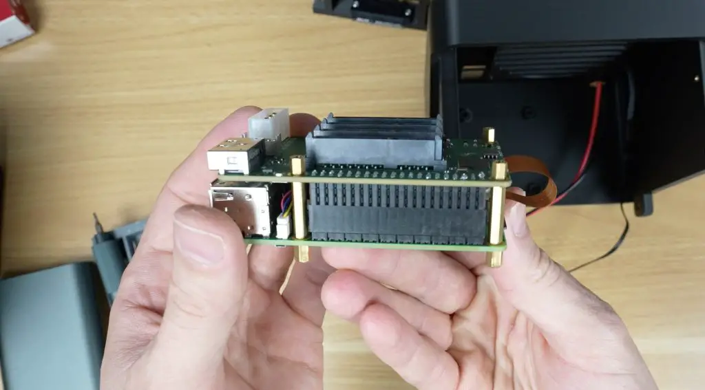
Next, the adapter boards are connected. One handles power, HDMI, and NVMe, another handles the GPIO pins, display, and fans, and the third routes the microSD card.
The Pi assembly is then secured to the enclosure with 10 screws (although I could only install 9, as the last one was blocked by the GPIO adapter).
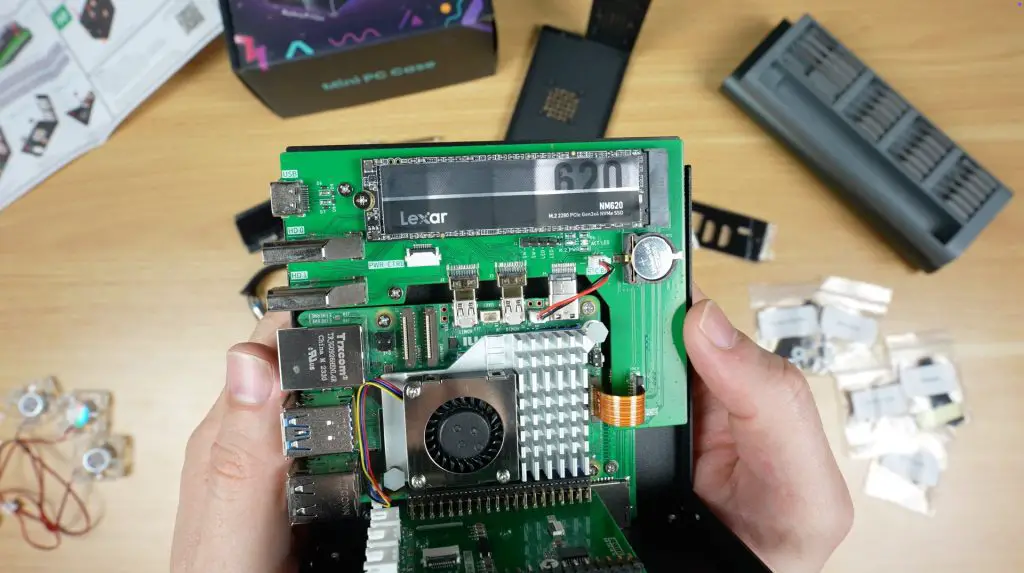
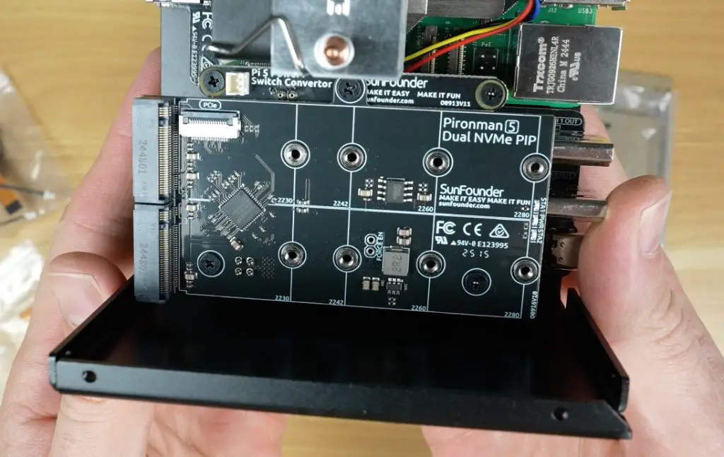
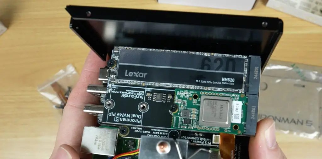
The NVMe drive can now be installed. I tested a 512GB Lexar NM620. The hat supports a range of drive sizes from 2230 to 2280.
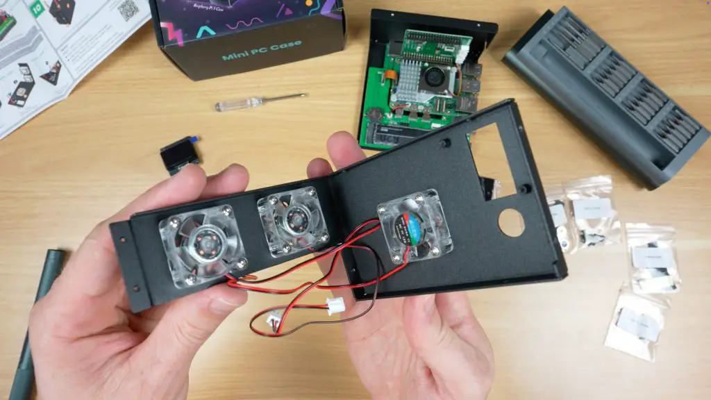
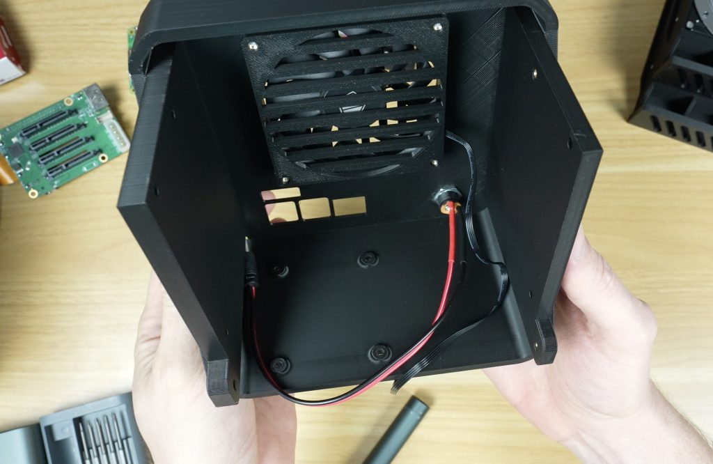
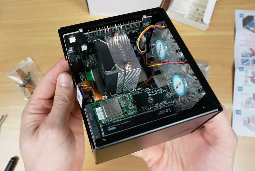
The three 30mm RGB fans are installed on the enclosure halves.
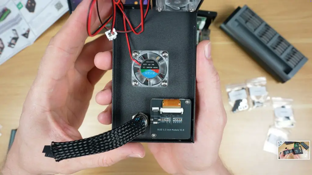
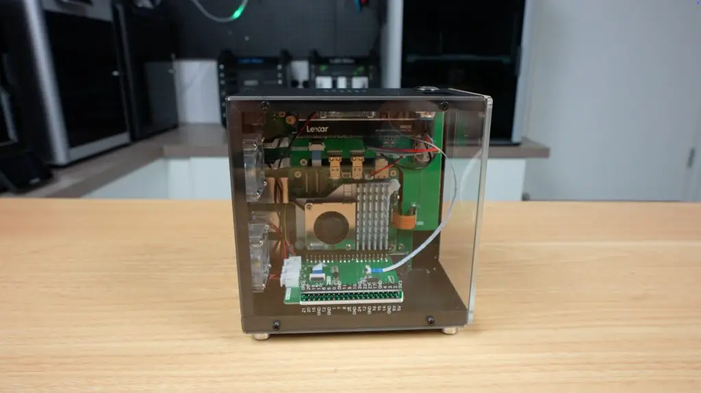
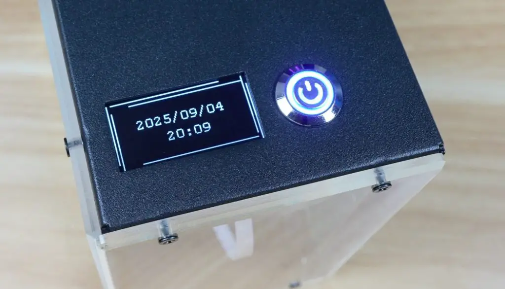
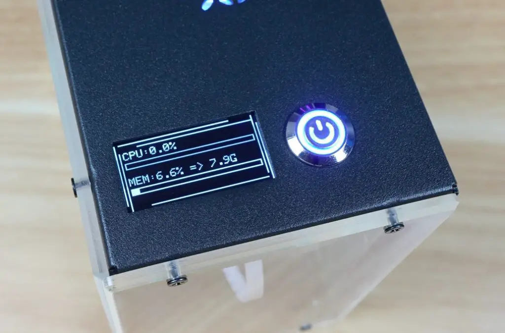
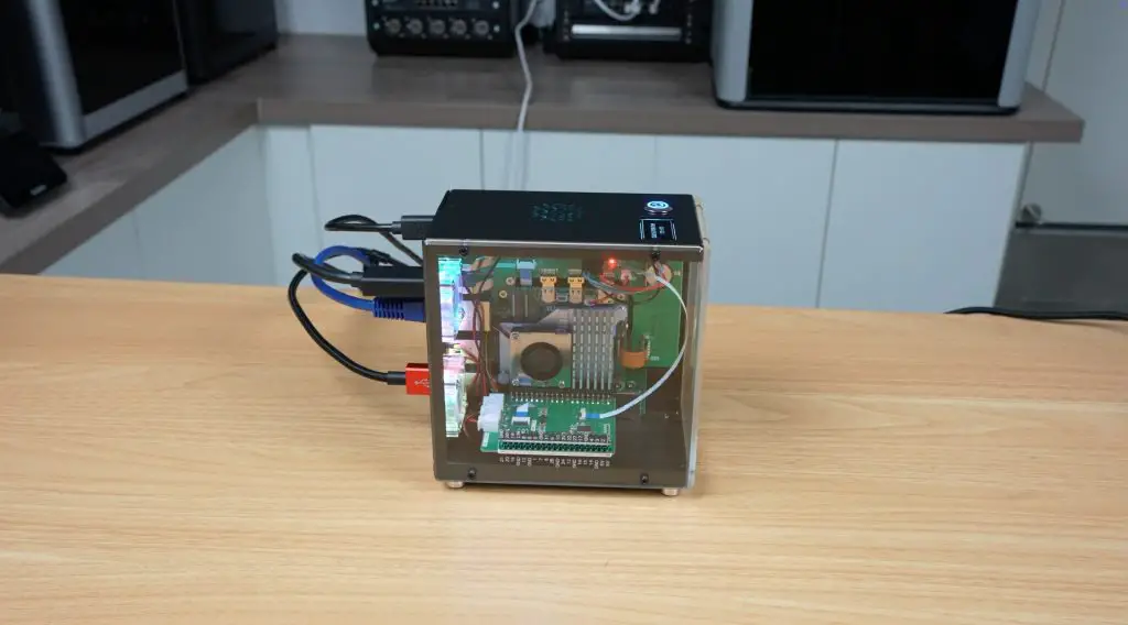
The power button and OLED display module are added. The display is a bit larger than usual at 1.3 inches compared to the typical 1-inch displays used on these types of cases.
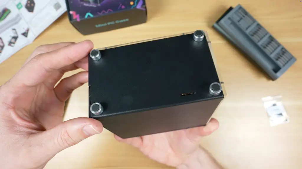
The enclosure halves are then screwed together, with the two clear acrylic side panels and rear port cover plate closing everything up. The clear acrylic panels are bevelled, giving the case a premium finish.
Finally, four aluminium feet are installed on the bottom, capped with rubber inserts for vibration dampening.
With that, the case assembly is complete.
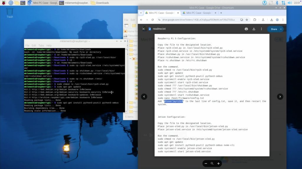
OLED Stats Display Software Setup
Getting the OLED display working requires installing a software script. This process is slightly more involved than simply running a GitHub script, but it isn’t particularly difficult. Hopefully Elecrow simplifies this in the future.
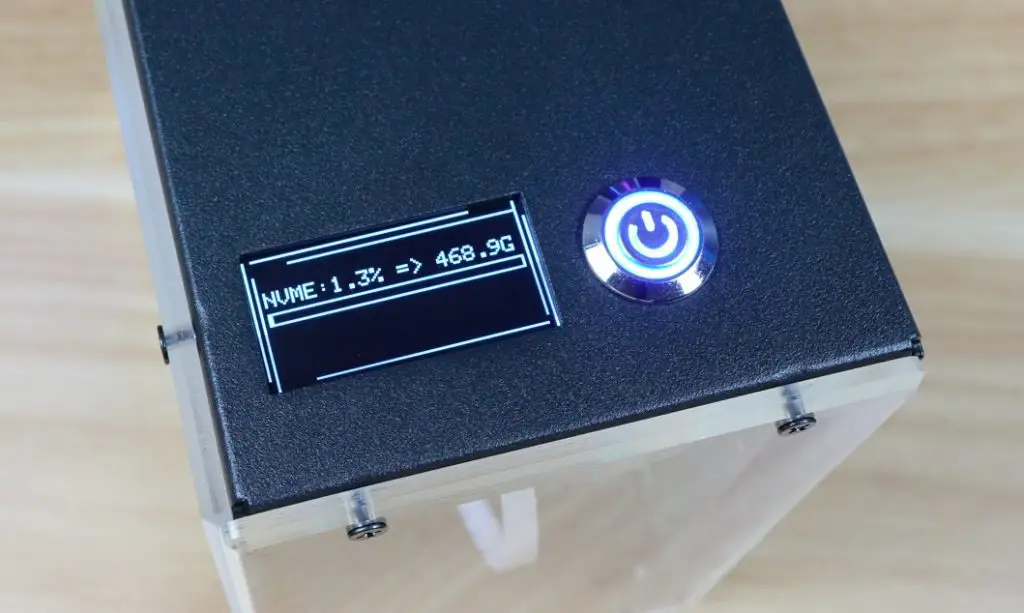
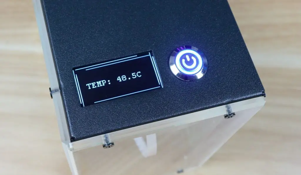
Once the script is installed and the Pi is rebooted, the display cycles through four pages showing;
System statistics
Storage capacity and utilisation
CPU temperature
Date and time
I would have liked some options here. Personally, I prefer a single screen showing system stats and temperature, but this arrangement works fine too.
Benchmarking and Thermal Testing
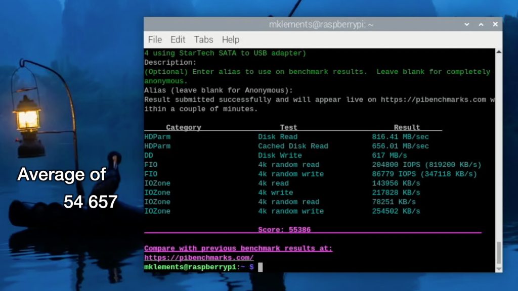
Since the case provides both NVMe support and active cooling, I ran a couple of tests to see how well it performs. I used James Chambers Pi Benchmarks script to test the NVMe drive performance and CPUBurn to test the cases thermals.
NVMe Performance
I tested the NVMe drive using the Pi Benchmarks script because this test favours random read/write performance which istypically how an OS uses the drive.
Over three runs, I achieved an average score of 54,657 (individual scores were: 53,638 / 54,947 / 55,386). This is about what you’d expect from a Lexar NM620 running at PCIe Gen 3 speeds on a Raspberry Pi 5, so there are no issues with the NVMe adaptor.
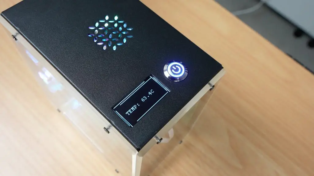
Thermal Performance
For thermal testing, I used CPUBurn, which fully loads all four Pi cores to generate the maximum amount of heat that the CPU is capable of producing.
The test began at 39°C in a 22°C room, which is a little high for idle but not concerning.
Within 4 minutes, the CPU temperature rose to 60°C.
It then stabilised around 63°C for the remainder of the 20-minute test.
This isn’t bad, but it isn’t outstanding either. There is plenty of unused space inside the enclosure, so Elecrow could have fitted a larger cooler to improve performance. I assume they were with the smaller one to keep costs down.
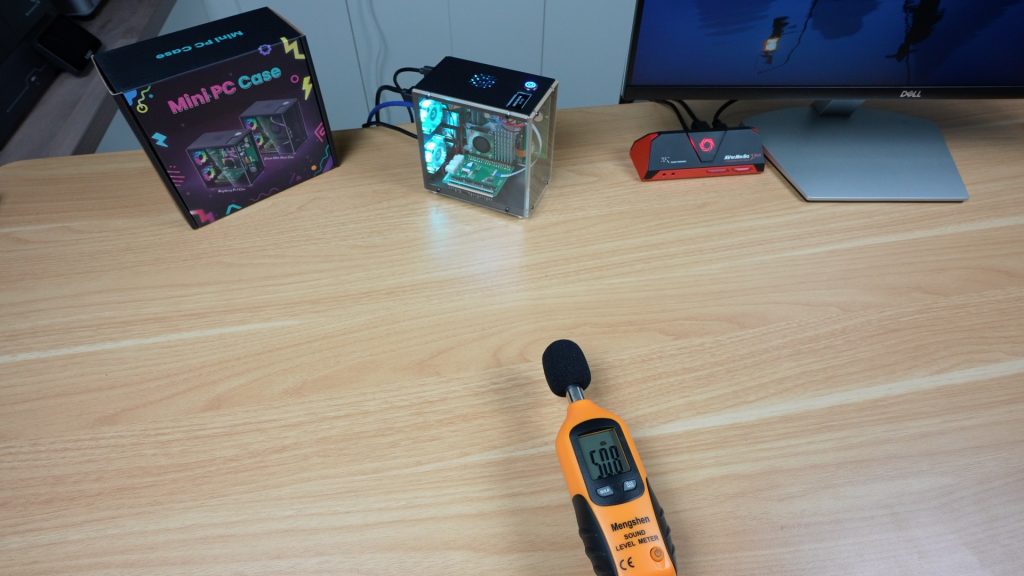
Fan Noise Level
One of the first things that I noticed when booting up the Pi was that the fans are quite loud. They are not PWM-controlled, so they spin up to full speed immediately. Being 30mm fans, they have quite a sharp noise profile.
At a distance of 20cm, I measured 50 dB, which is on the noisy side for a case that’s designed to be used on your desktop.
The power button works as intended. Holding it initiates a shutdown sequence, and it then cuts power to the fans and the Pi itself, leaving the system ready for the next startup.
Final Thoughts
For just $40, this case delivers good value. You get NVMe storage support, redirected ports for a cleaner desktop setup, a functional OLED display and active cooling that keeps the Pi stable under full load. It makes the Raspberry Pi 5 feel more like a mini desktop computer than an exposed board on your desk.
Being a first generation product, there are, however, some minor quirks to it:
As shown earlier, one screw behind the GPIO adapter is nearly impossible to install. This could quite easily be resolved by installing it at an earlier stage.
The display setup process could be easier, ideally with a direct download link rather than a QR code. The Pi doesn’t have a camera installed, so the QR code isn’t particularly helpful.
Cable management could be improved. For example, the OLED ribbon cable dangles in the most visible part of the case and could easily have rather been incorporated into the adaptor board alongside it.
The redirected microSD slot comes out in a rather strange spot at the bottom of the case.
The fans are noisy and could benefit from PWM control.
If these aren’t significant issues to you, then the Elecrow Mini PC Case is a very well-priced option for Pi 5 owners who want a desktop-style enclosure. You can check out the case on Elecrow’s web store.
Let me know what case you’ve got your Pi 5 in in the comments section below.
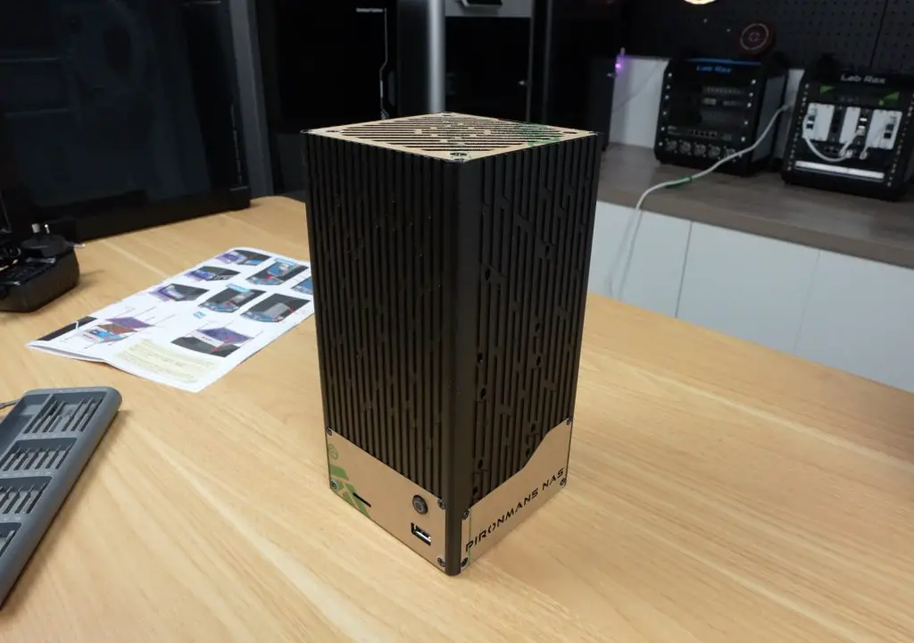
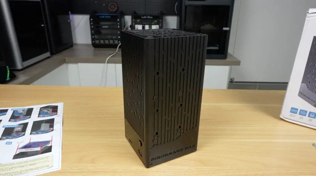
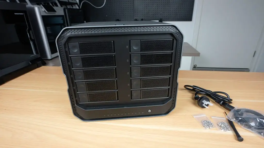
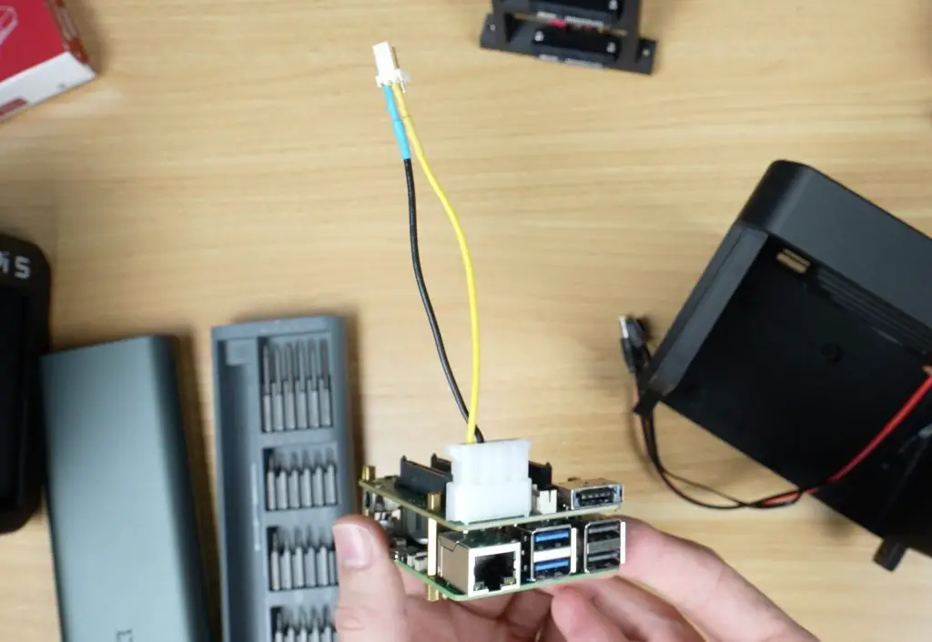
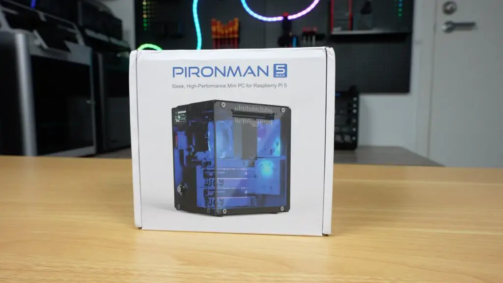
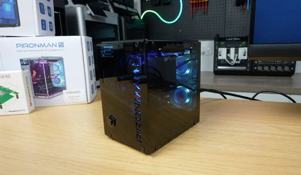
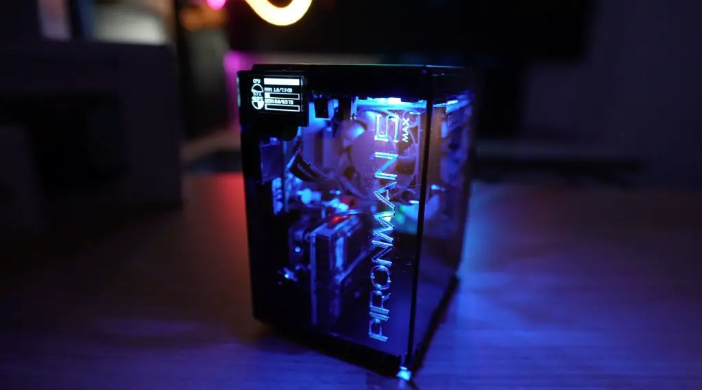
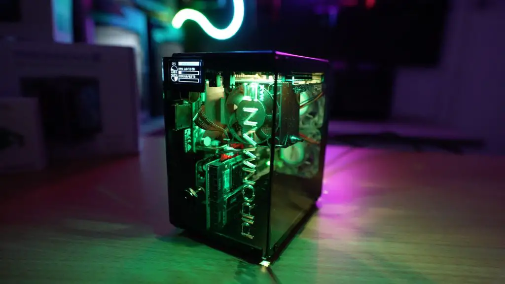
The Pironman 5 NAS case is the latest addition to Sunfounder’s Pironman series, this time designed specifically for the Raspberry Pi 5. Unlike the previous models, this version is built to turn your Pi into a compact yet capable NAS (Network Attached Storage) system.
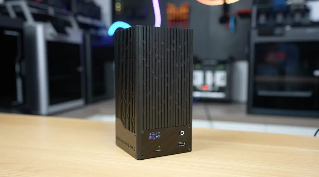
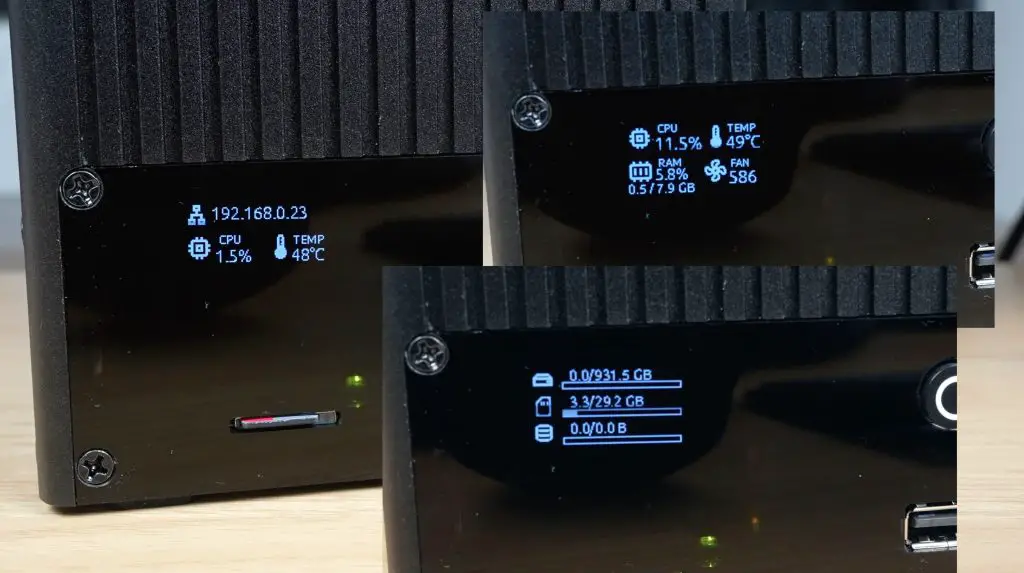
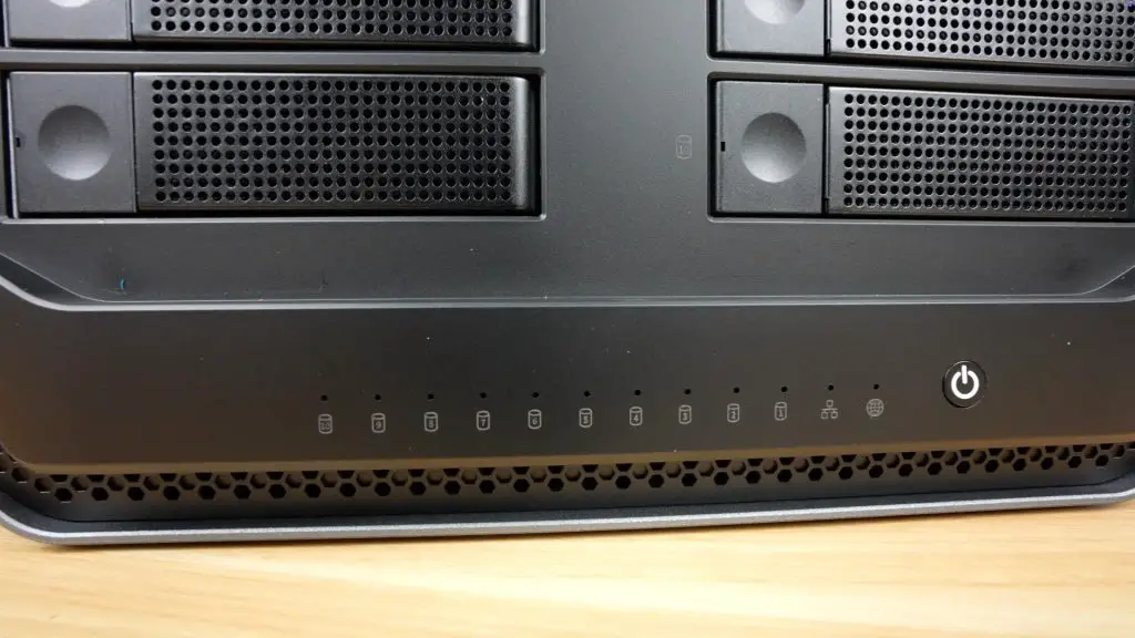
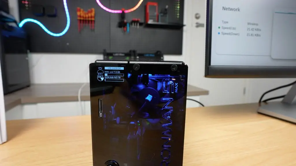
What makes it stand out is its ability to house two drives, either 2.5-inch SSDs or full-size 3.5-inch HDDs. On top of that, the case comes with some great additional features like a built-in 2.5G network adapter, a large 90mm cooling fan and a front-facing OLED stats display.
It’s important to note that this is still a beta product. Sunfounder are in the internal testing stage, and the case hasn’t yet gone into full production. So while I’ll cover the full build and performance here, some things may change before the official launch later this year.
Here’s my video build and testing of the NAS, read on for the write-up;
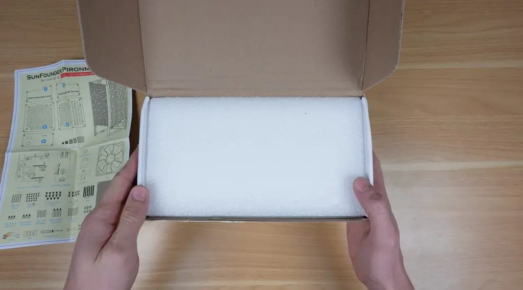
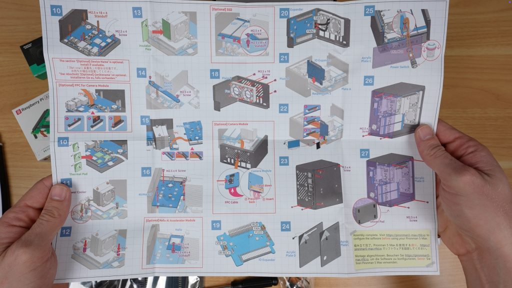
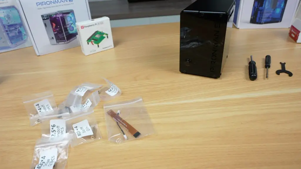
Inside the box, the first thing you’ll find is the assembly instruction sheet.
Beneath that is another well-padded white box containing the aluminium enclosure, along with multiple accessory packs that hold all of the panels, components, and PCBs.
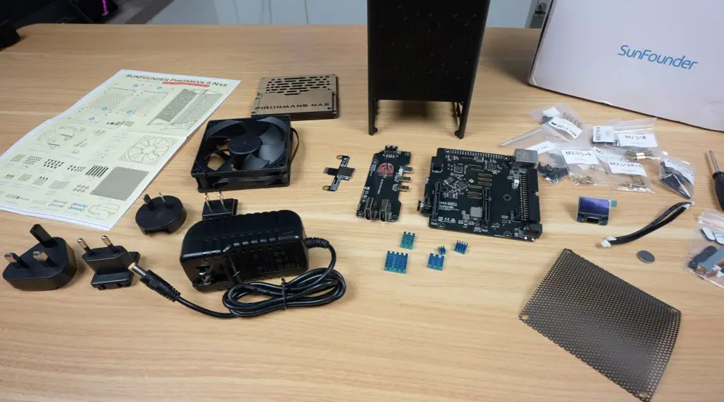
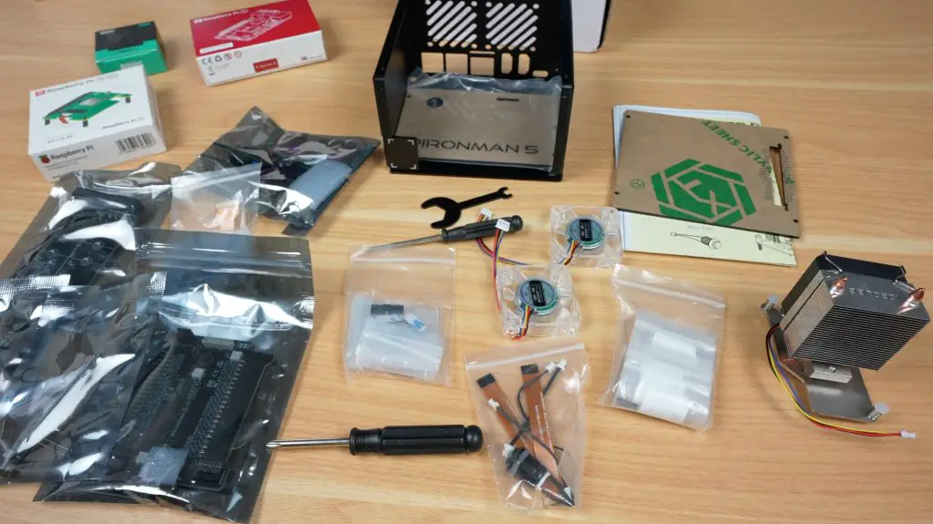
Here’s everything included in the kit:
Aluminium housing
Acrylic panels and the 90mm cooling fan
Universal 12V 4A power supply
Several adapter/control PCBs and heatsinks for the Pi
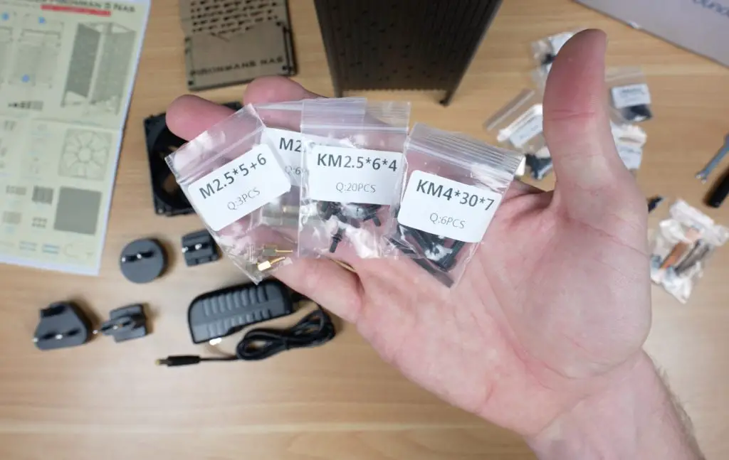
OLED display module, cables, screws, and mounting hardware
A set of basic assembly tools
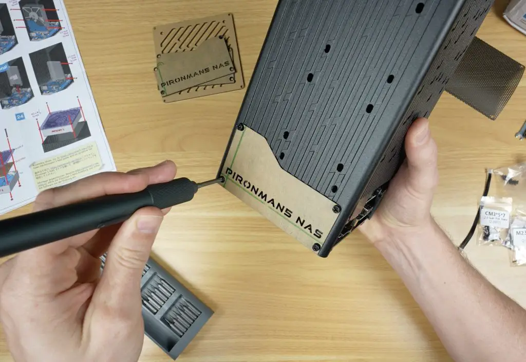
As with other Sunfounder kits, the screws are clearly labelled, and the assembly process is made easy by their detailed, picture-guided instruction sheet.
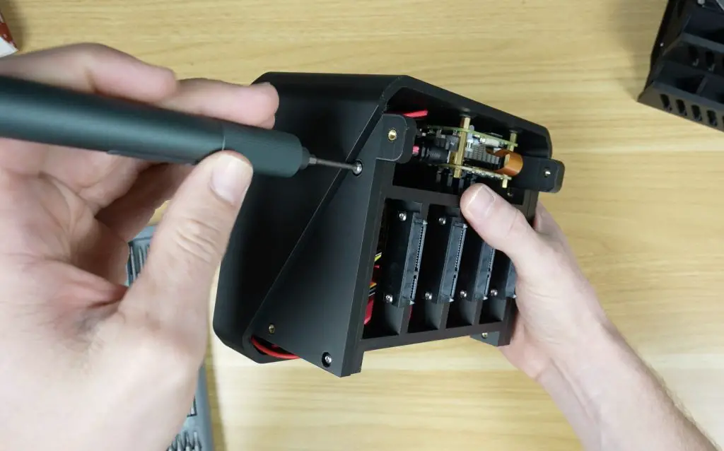
Assembling the Pironman 5 NAS Case
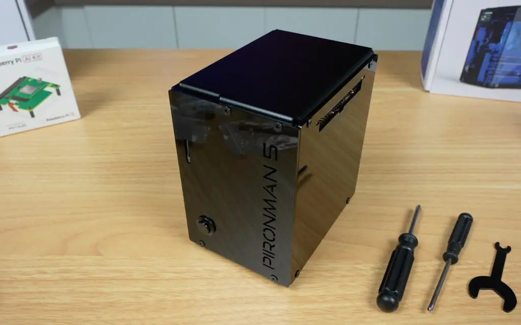
Putting the Pironman 5 NAS case together is fairly straightforward. The acrylic panels even feature countersunk screw holes, giving the finished case a much cleaner look.
Here is the basic build process:
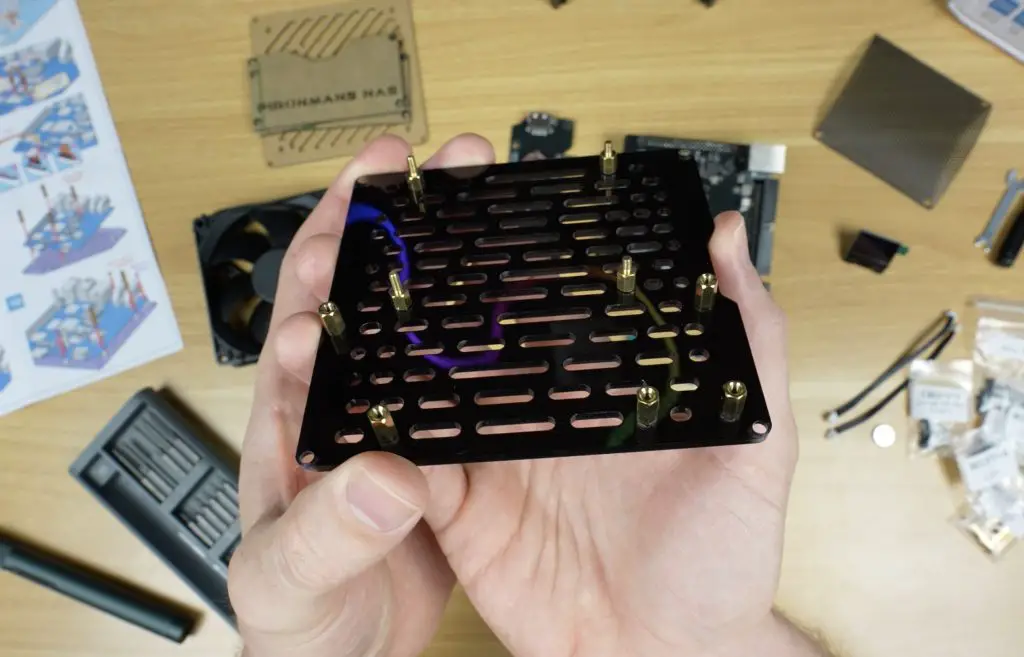
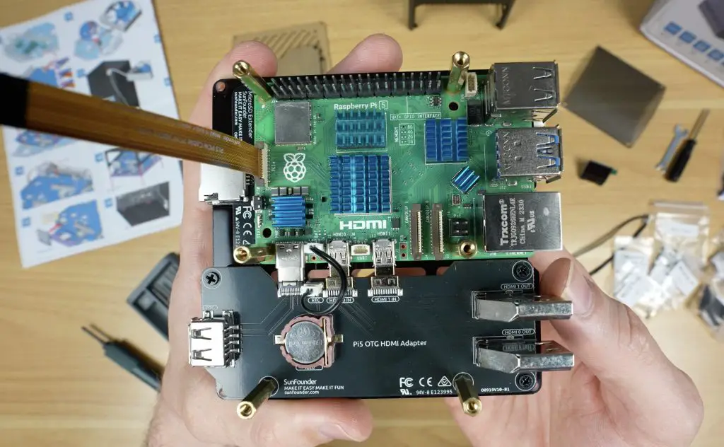
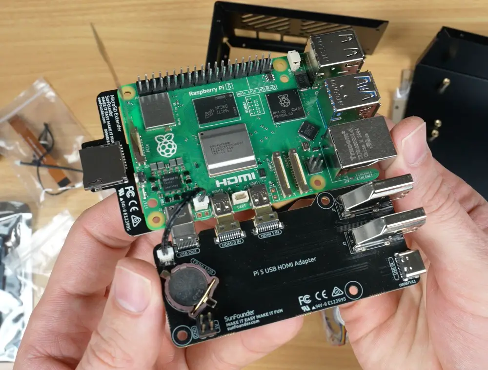
Add standoffs to the acrylic base panel, which will support the Pi assembly.
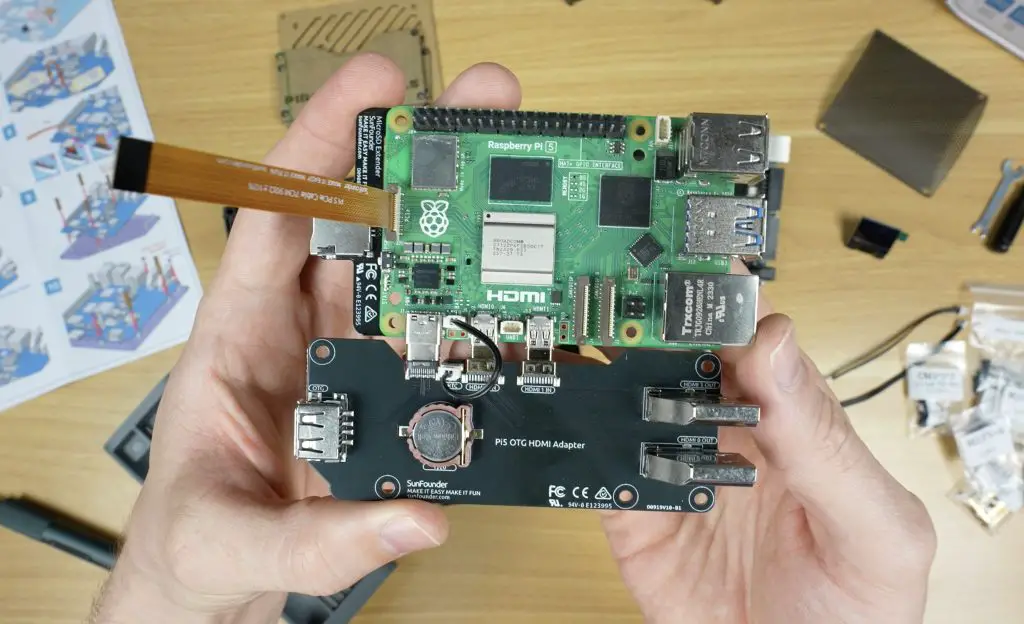
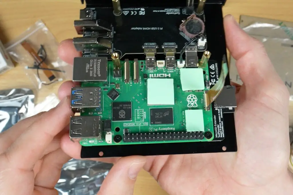
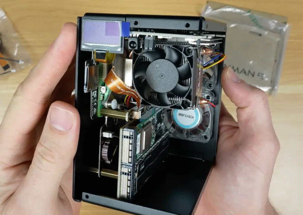
Mount the Raspberry Pi and attach the adapter boards, securing the stack with additional standoffs and screws.
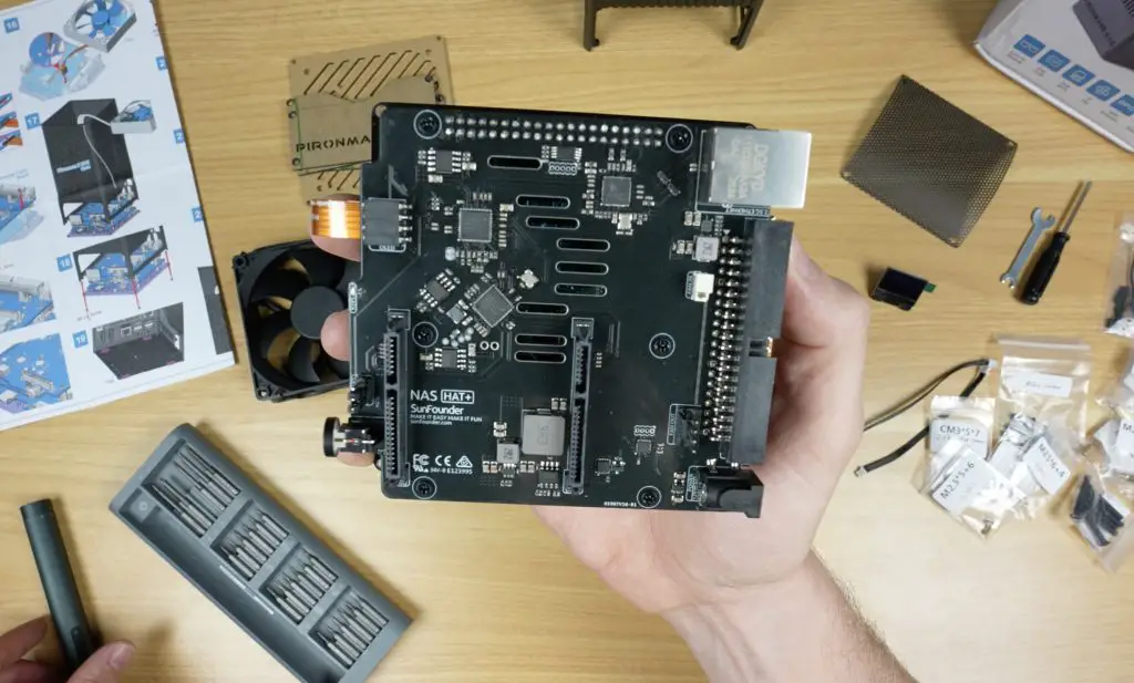
Install the five supplied heatsinks on the Pi’s key components. The CPU heatsink is on the smaller side, but we’ll see later how well it performs.
Attach the main SATA and control HAT to the Pi.
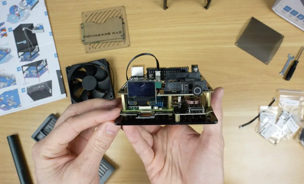
Plug the OLED display into its dedicated 4-pin socket.
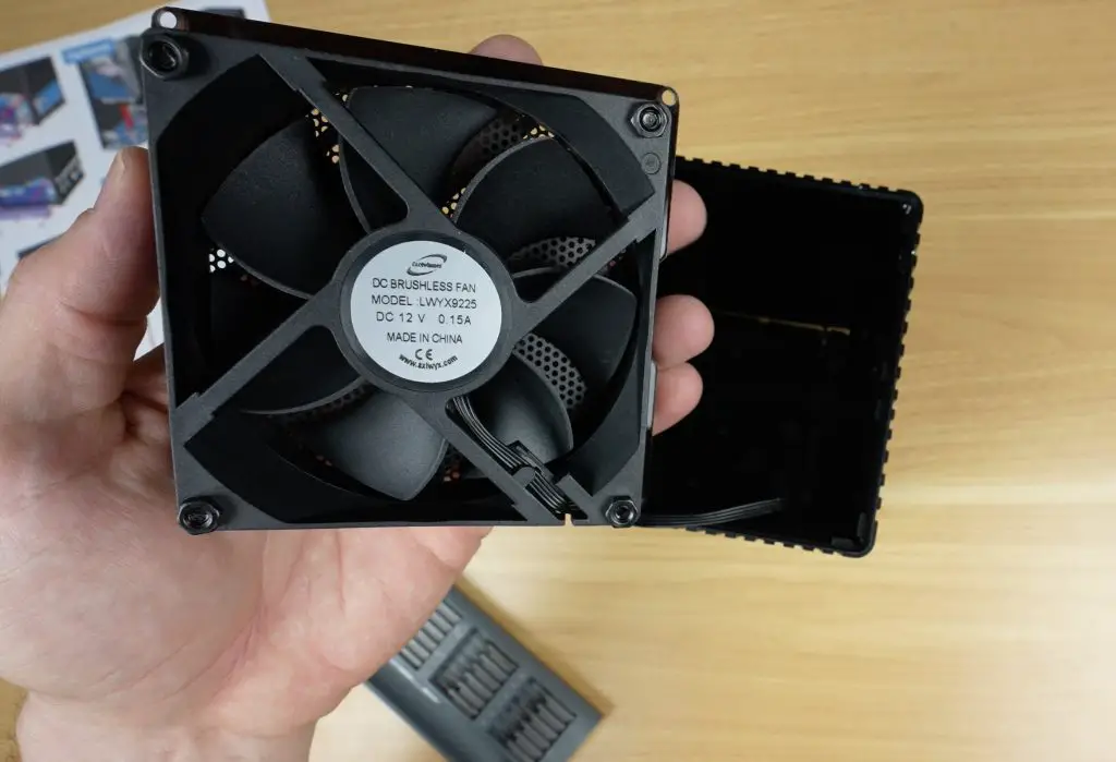
Connect the 90mm fan.
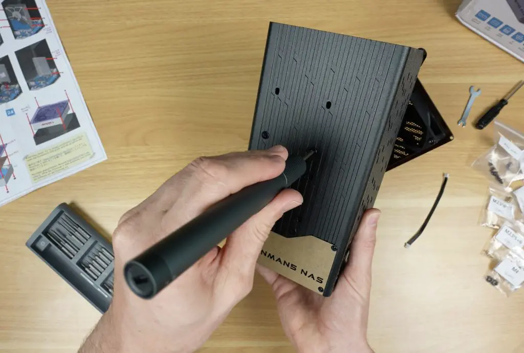
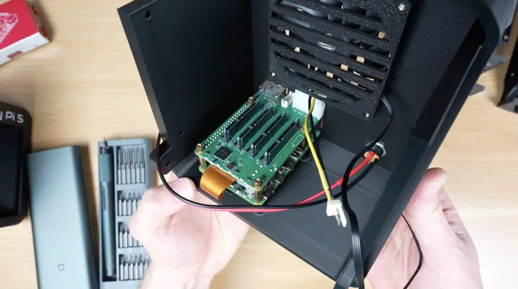
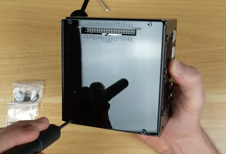
Mount the completed Pi assembly into the aluminium housing and add rubber feet to the base.
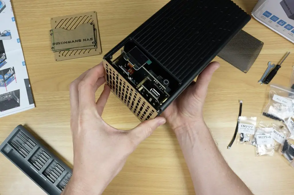
Secure the acrylic panels onto three sides of the case, and mount the fan to the top acrylic cover.
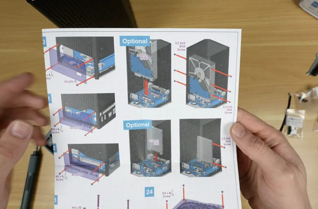
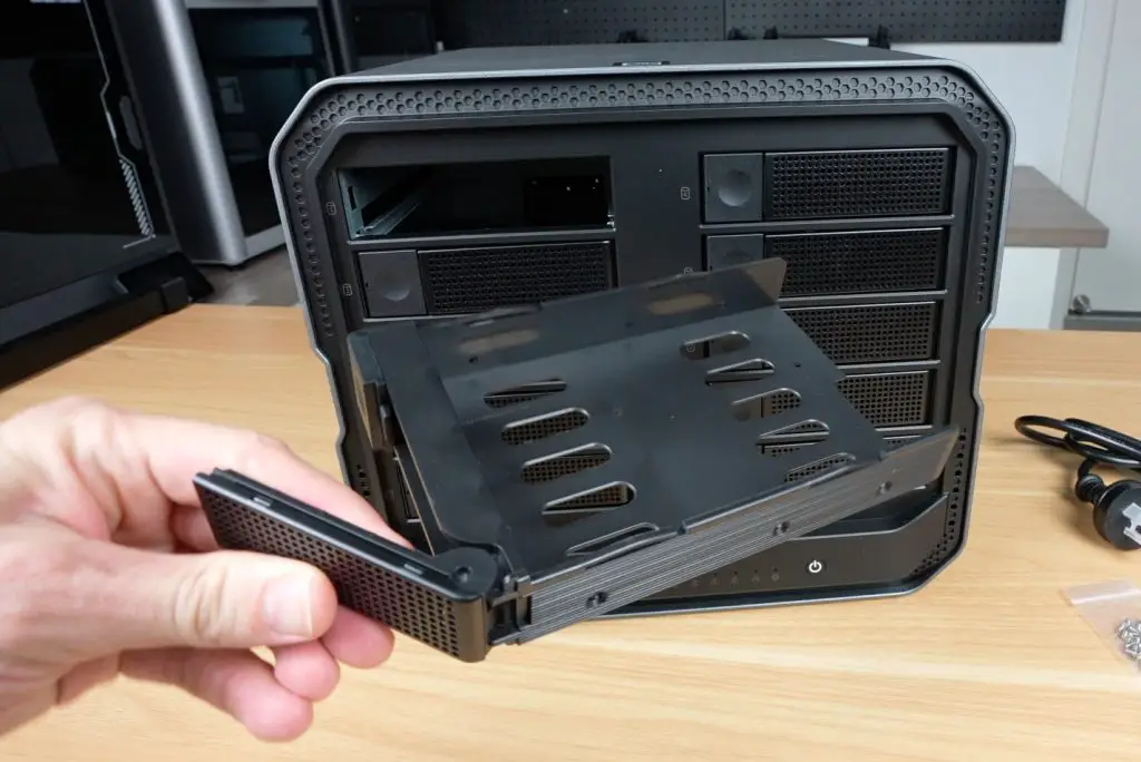
The drive bay section of the enclosure is cleverly designed to fit either two 3.5-inch drives (secured on both sides) or two 2.5-inch drives (secured on one side).
I personally would have liked to see an option for four 2.5-inch drives, but given that 3.5-inch drives remain popular for high-capacity NAS builds due to their cost-effectiveness, this design fills a gap in the market.
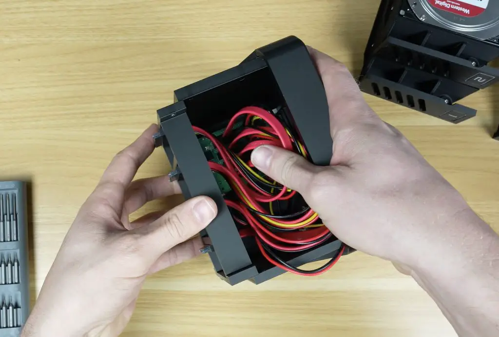
For my testing, I installed a pair of 1TB Crucial BX500 SSDs before closing up the case.
The finished enclosure measures 109mm x 109mm x 216mm, which is really compact considering it can house two full-size 3.5-inch drives.
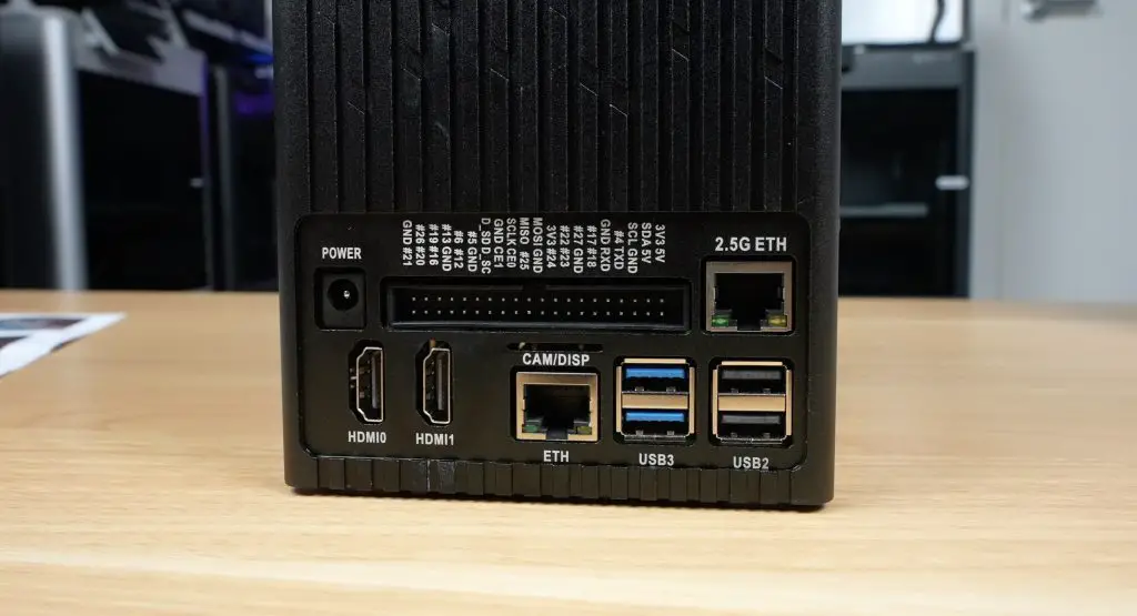
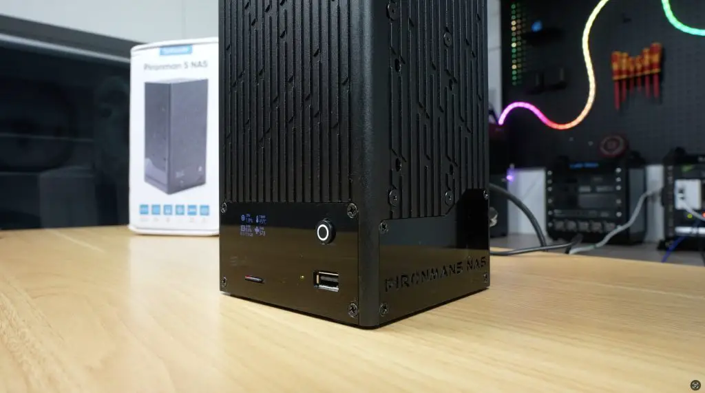
Ports and I/O on the NAS
The Pironman 5 NAS case provides plenty of connectivity, expanding on the Pi’s basic IO through the included hat:
Raspberry Pi’s standard Gigabit Ethernet, 2x USB 3.0, and 2x USB 2.0 ports
A ribbon cable slot for Pi camera or display connectors
Two full-size HDMI ports from the adapter board
12V barrel jack input
A full GPIO pin header passthrough
A 2.5G Ethernet port, a standout feature for a Pi-based NAS
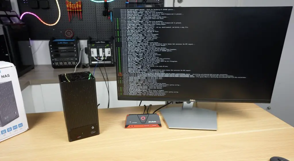
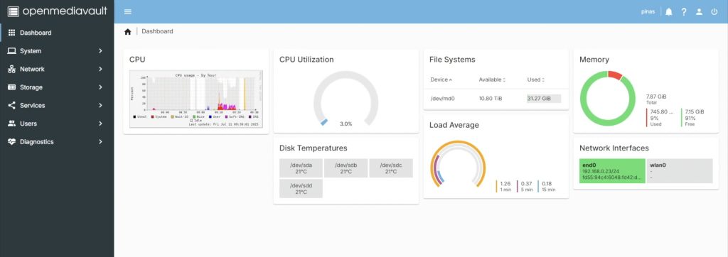
Operating System and Software Setup
Sunfounder recommends using Open Media Vault (OMV), but being a Raspberry Pi there are other options for operating systems if you’d like to use an alternative. The setup process is as follows:
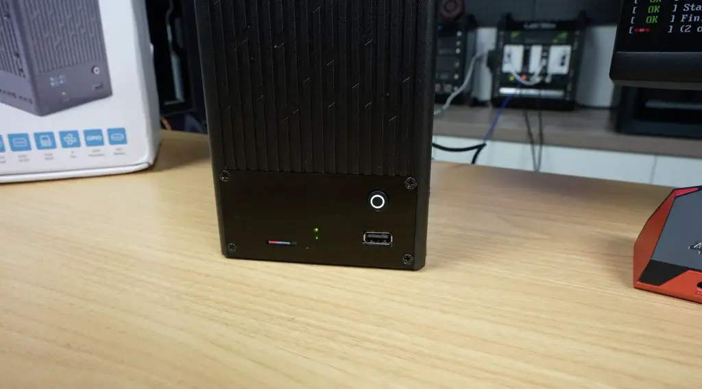
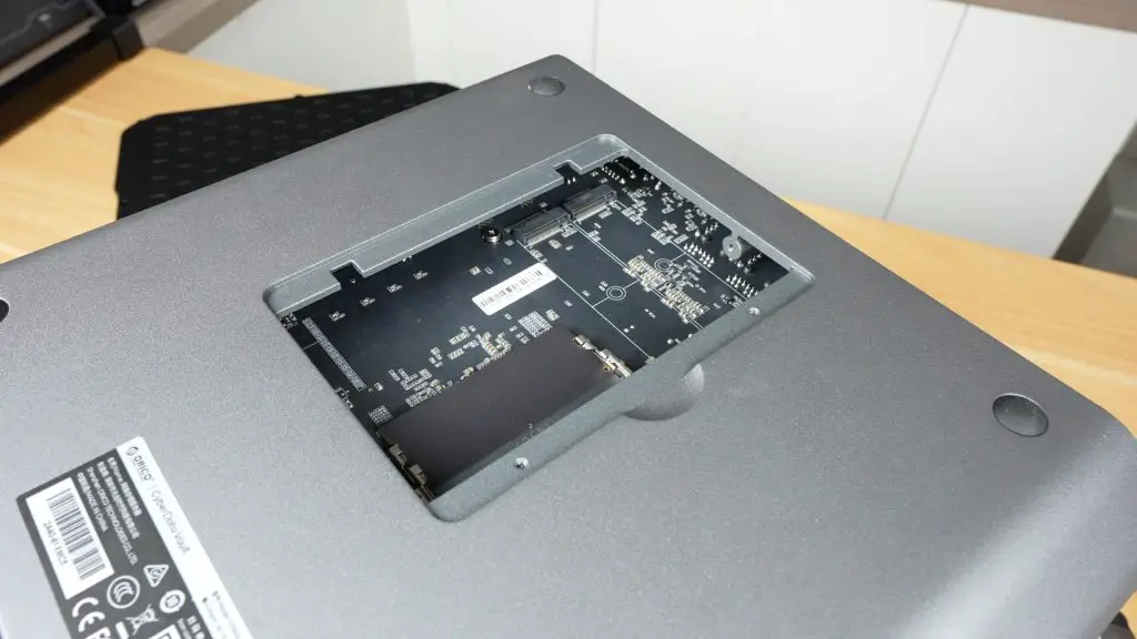
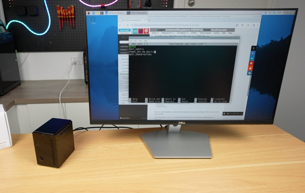
Flash Raspberry Pi OS Lite to a microSD card and insert it into the case’s front slot.
Update the Pi and install OMV.
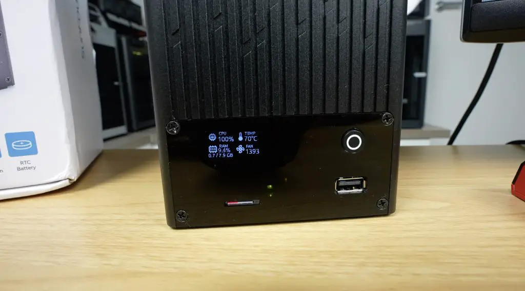
Install the Pironman script to control the OLED display.
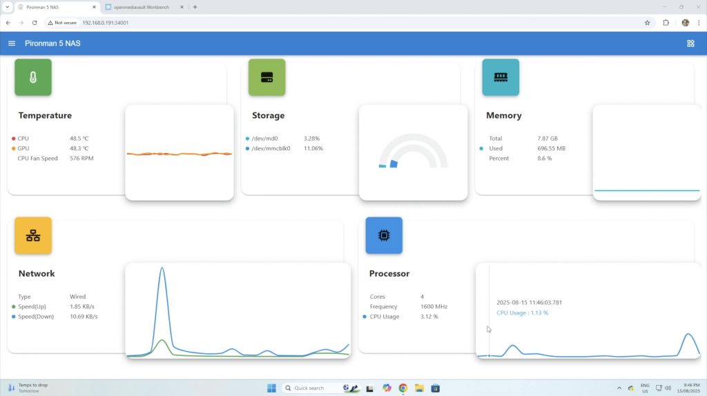
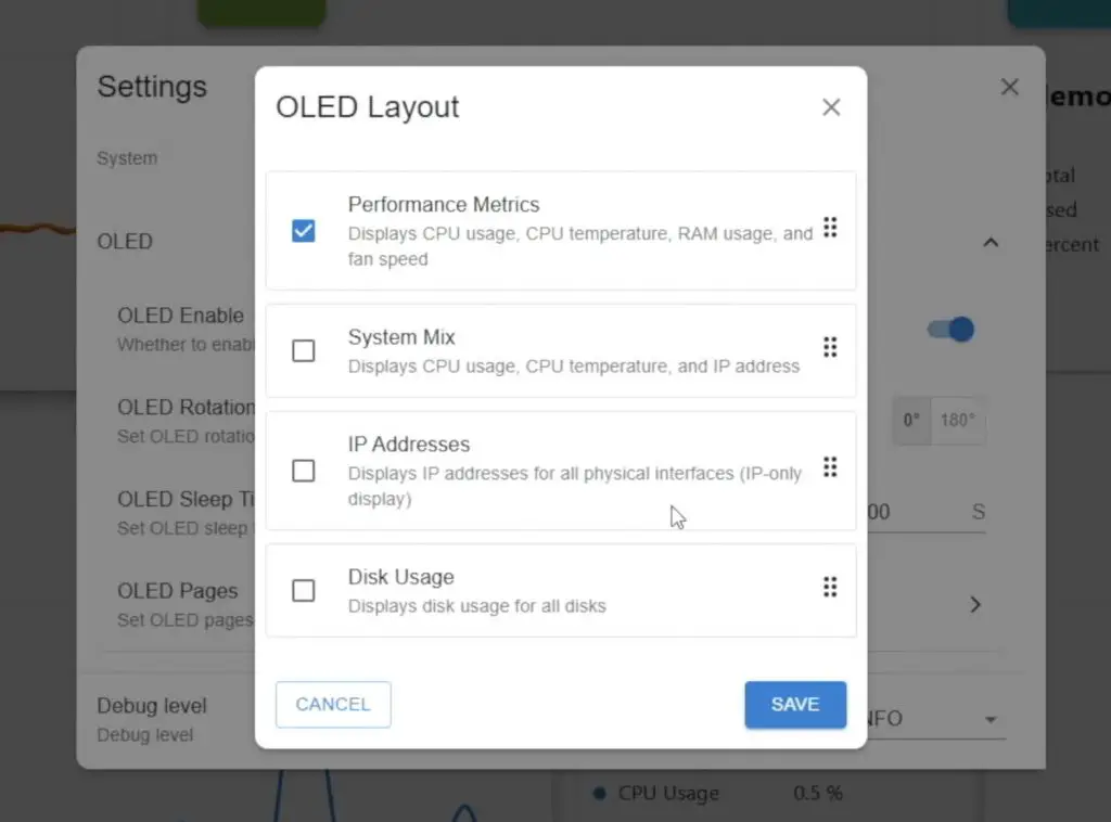
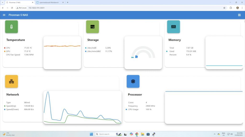
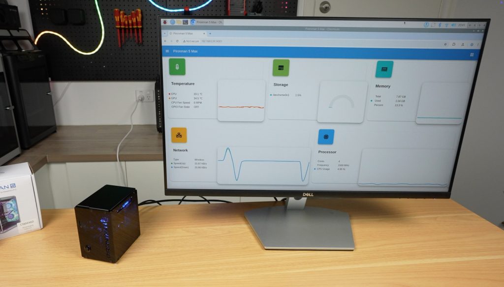
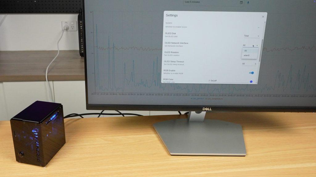
Like other Pironman cases, this one also includes a web dashboard to monitor stats and adjust settings. The OLED display itself has multiple options, allowing you to choose a fixed readout or cycle between different stats.
To manage storage, log into the OMV web dashboard via the Pi’s IP address. From there, create a file system, a shared folder, and set up an SMB share to access the NAS from a Windows PC.
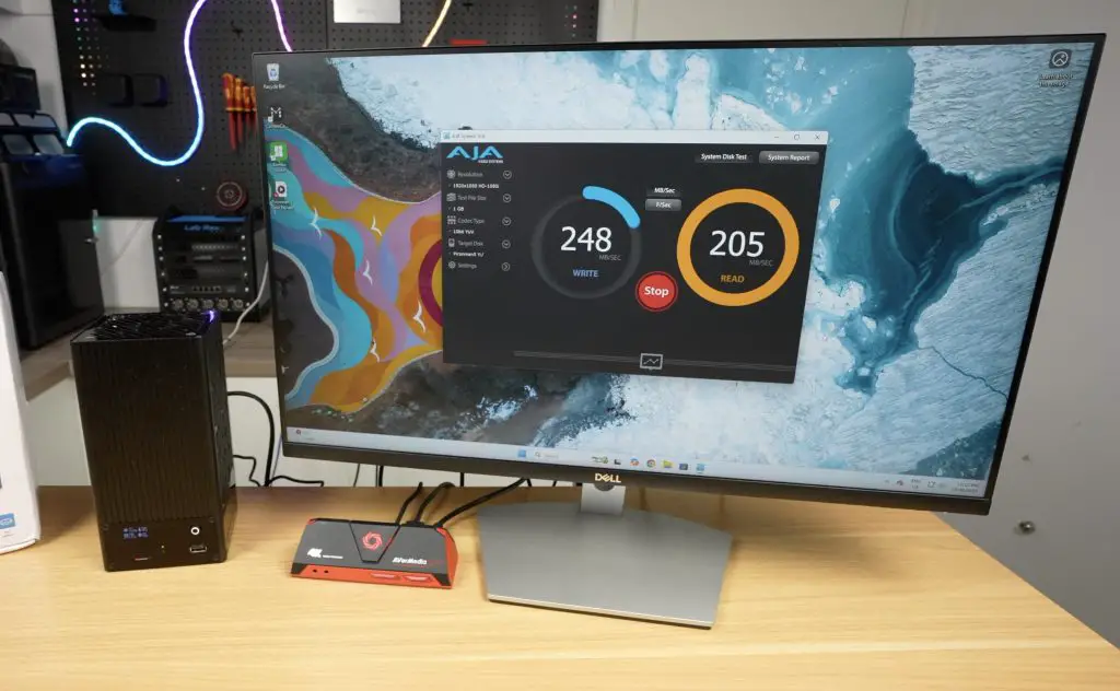
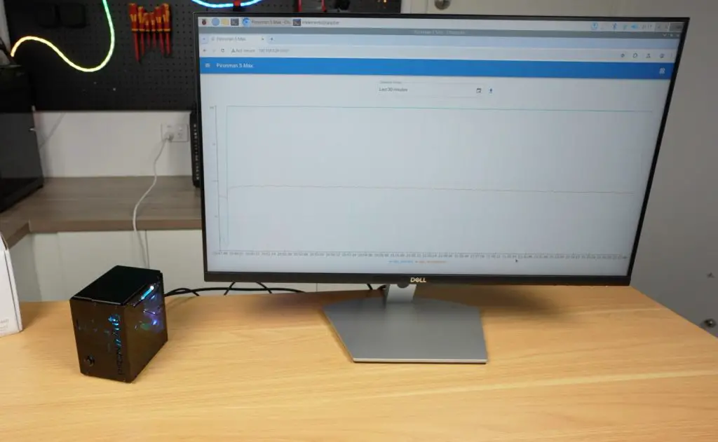
Performance Testing the Pironman 5 NAS Case
With everything configured, I ran a series of transfer tests to test the performance of the hat and 2.5G network connection.
1GB file test → Writes: ~240MB/s | Reads: ~200MB/s
16GB file test → Writes: ~230MB/s | Reads: ~170MB/s
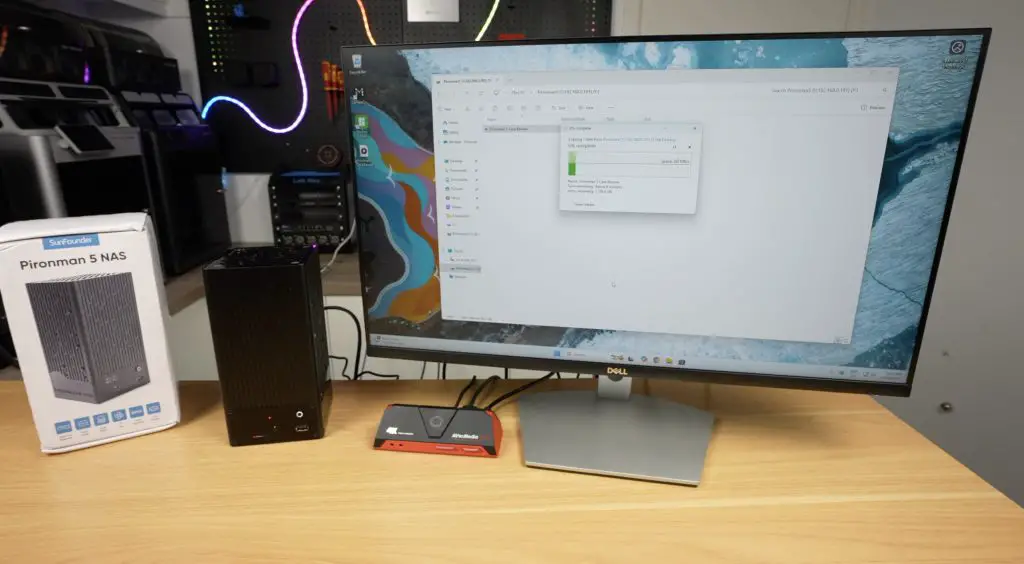
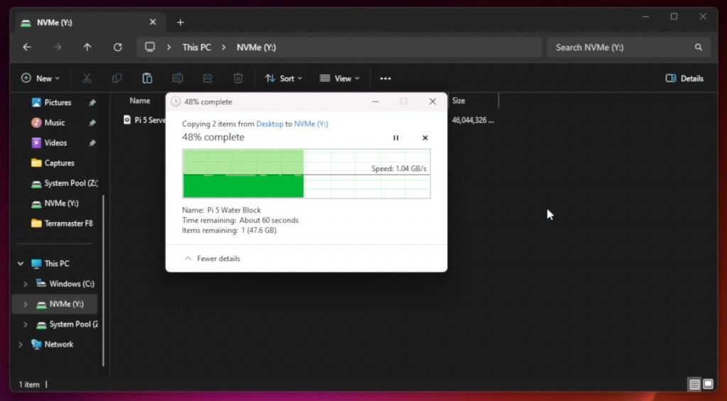
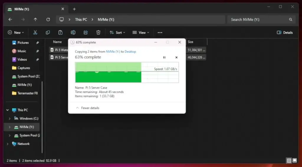
Doing a realworld file transfer of a 60GB video file to and from the NAS in Windows 11, I got;
60GB video file → Writes: ~260MB/s (peaking near 280MB/s) | Reads: ~260MB/s (very consistent)
These results are right in line with what you’d expect from a 2.5G network connection and show no issues with bottlenecking on the single available PCIe lane on the Pi.
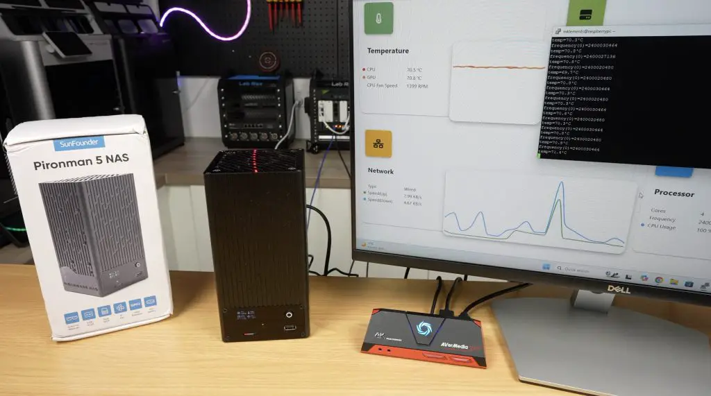
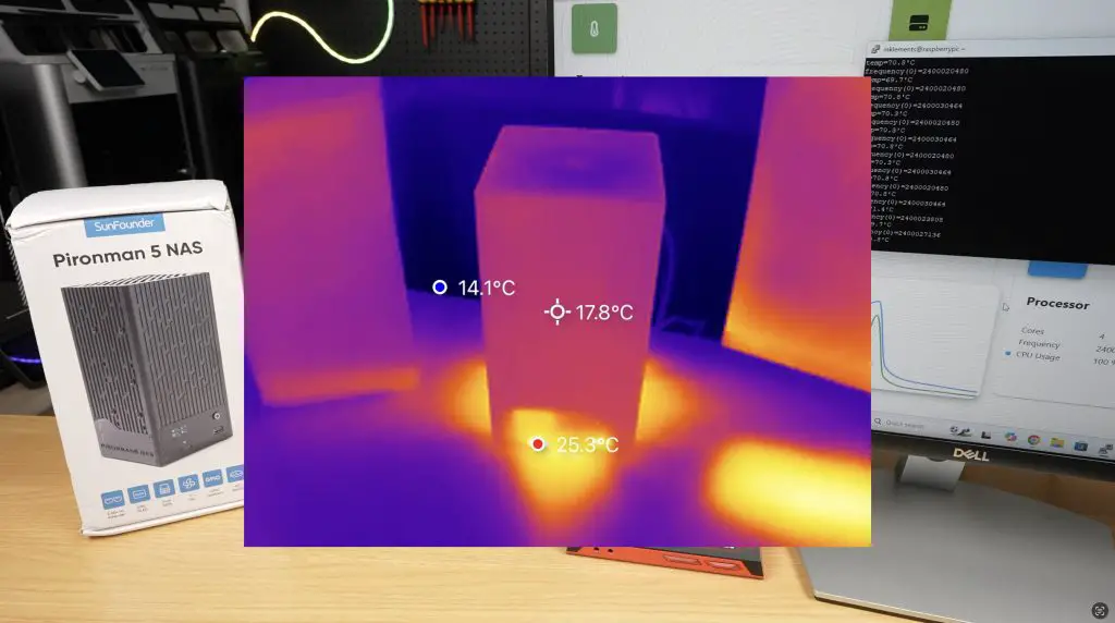
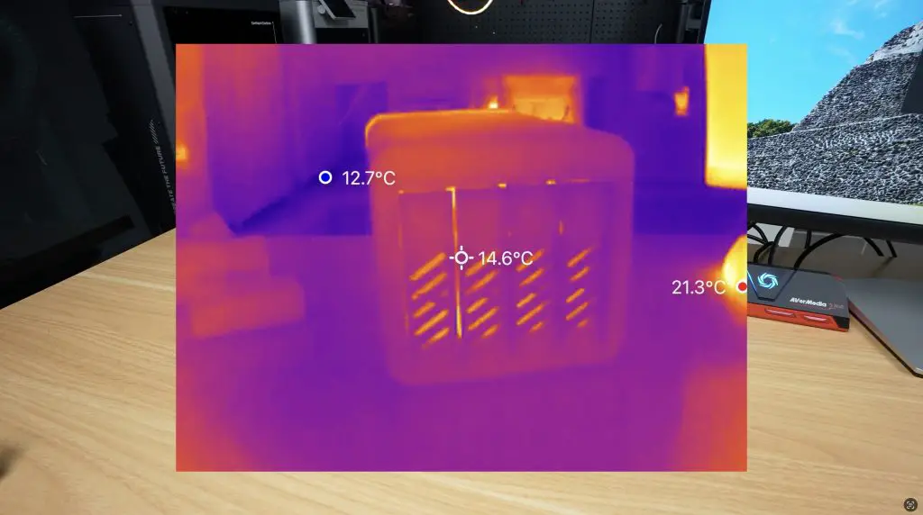
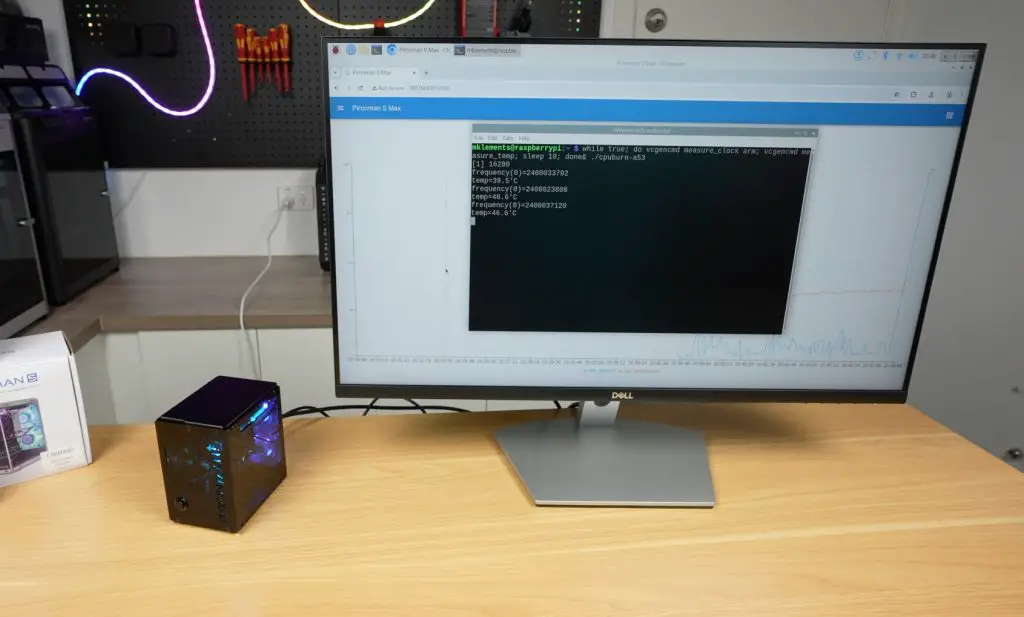
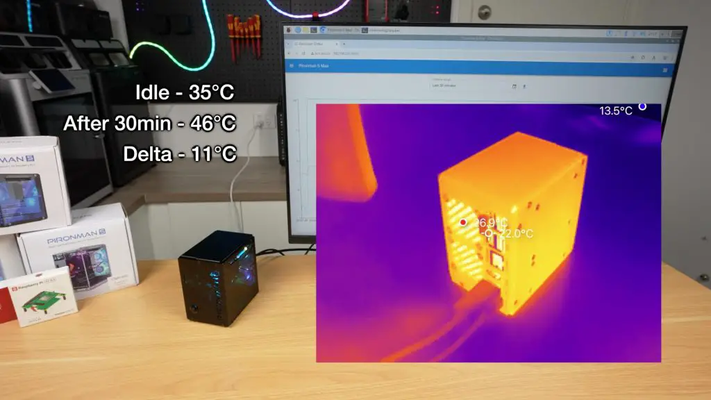
Cooling and Thermal Testing
The large 90mm fan keeps drive temperatures very low during heavy file transfers.
The Pi’s CPU, however, runs hotter. At idle, the CPU started at 48°C, climbing quickly to 70°C under load during a 20-minute stress test using CPU Burn. The small CPU heatsink is adequate for basic NAS use but not ideal for workloads like RAID parity or media encoding. A larger aftermarket heatsink would be recommended for those cases.
Fortunately, since this is still a beta kit, SunFounder will likely address cooling improvements in the final version.
The aluminium housing also helps dissipate heat, and airflow inside remains decent even with 3.5-inch drives installed.
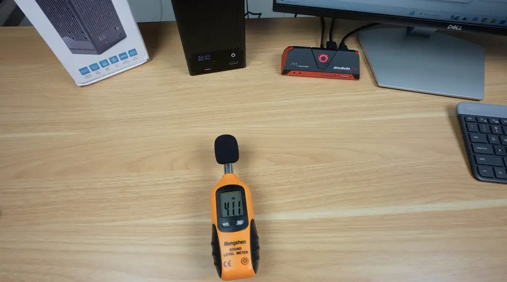
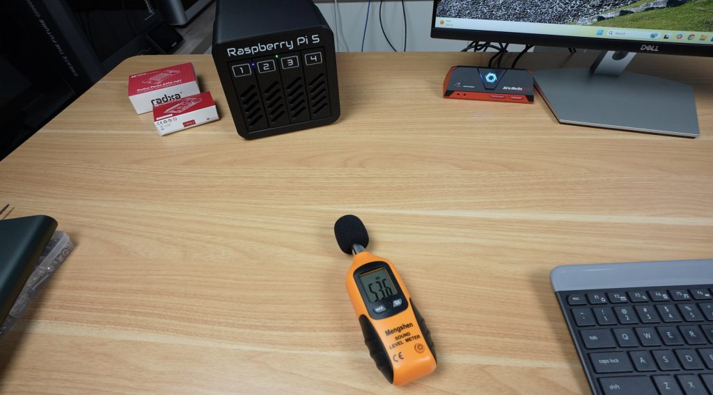
As for noise levels, the 90mm fan is PWM controlled. At full load, it reached about 41dB (which is not significantly loud), but when running below 800RPM it’s essentially silent. With mechanical drives installed, you’d likely never hear the fan over the drive noise anyway.
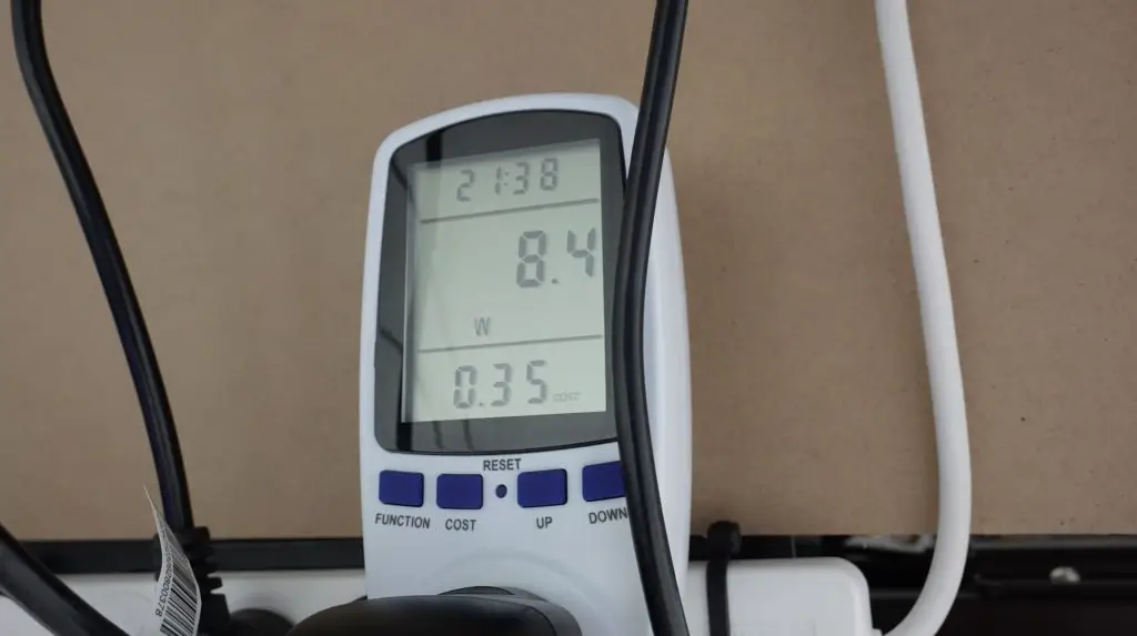
Power Consumption
I tested power consumption using a wall adaptor and took readings both at idle and with the CPU full loaded during the thermal test, while also copying large video file to the NAS. For these two tests, I got;
Idle: ~8W
Full load: ~14W
These are impressively low numbers for a dual-drive NAS, thanks to the Pi’s efficiency. With mechanical HDDs, consumption would be slightly higher, but OMV allows you to set drive spin-down times to save even more power when idle.
Final Thoughts on the Pironman 5 NAS Case
The Pironman 5 NAS case is another great addition to SunFounder’s lineup. It’s well-built, easy to assemble, and packed with useful features like the OLED display and 2.5G networking.
Since it’s still in development, SunFounder haven’t released official pricing yet. But if it lands in the $100–$120 range, I think it would be excellent value for a Pi-based NAS kit.
I’d personally love to see a version that supports four 2.5-inch drives, but the flexibility of using 3.5-inch HDDs is a big selling point that very few other Pi enclosures offer.
Overall, this is shaping up to be a compact, efficient, and capable NAS solution for the Raspberry Pi 5. Let me know what you think of it in the comments section below.
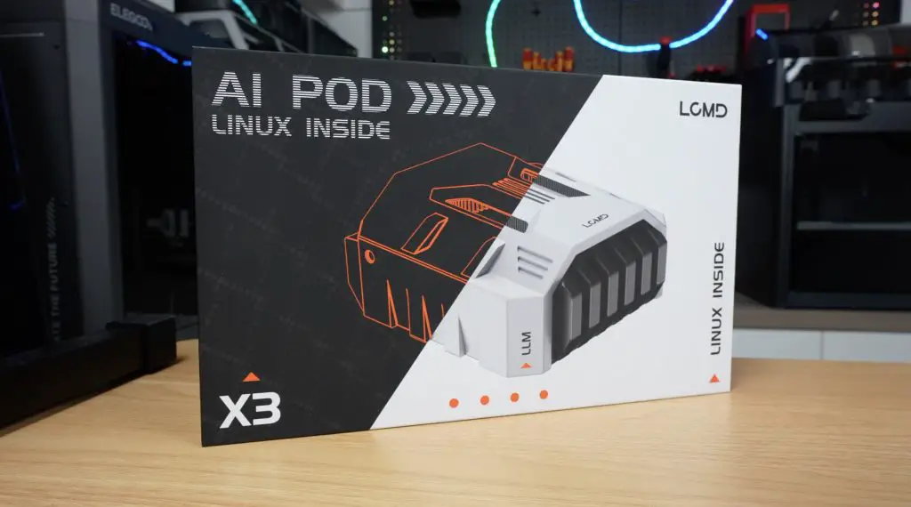
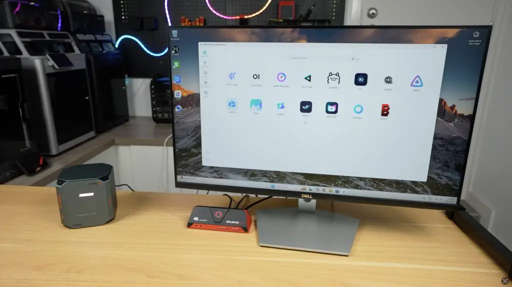
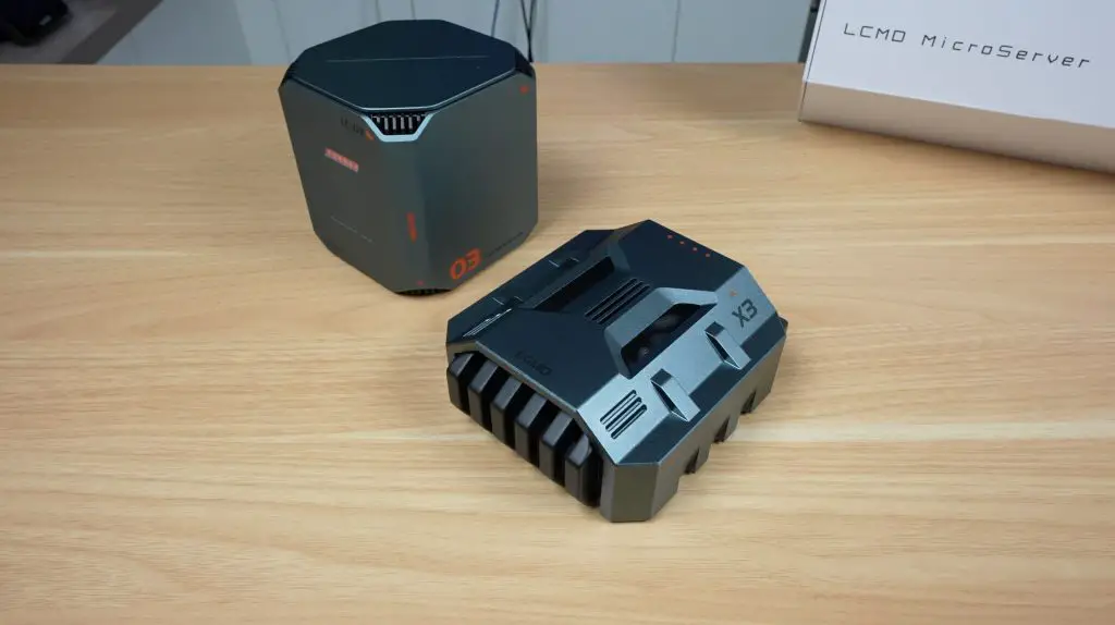
If you’re into homelabs or setting up your own personal cloud server, I’ve got something really interesting to share with you today. This is the new LCMD Microserver, and its optional add-on, the AI Pod, a compact computing module designed to supercharge the system’s performance for AI-related tasks.
Together, these two devices form a powerful, accessible homelab solution. They’re designed to help even less experienced users set up an advanced personal server quickly and easily.
With the pair, you can do things like:
Run Docker containers
Host media servers
Set up your own Git server
Build an AI-searchable photo and video library
Backup your data
Let’s dive in, unbox them, and see how they perform.
Here’s my video review of the LCMD Microserver and AI Pod, read on for the written review;
Where To Buy The LCMD Microserver & AI Pod
The LCMD Microserver and AI Pod are planned to be crowd funded through Kickstarter, with their campiagn starting soon. Check out the LCMD Prelaunch Page in the meantime.
Some of the above parts are affiliate links. By purchasing products through the above links, you’ll be supporting my projects, at no additional cost to you.
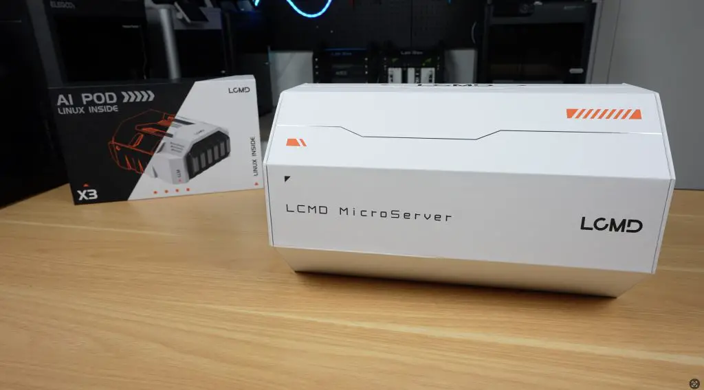
Unboxing the LCMD Microserver
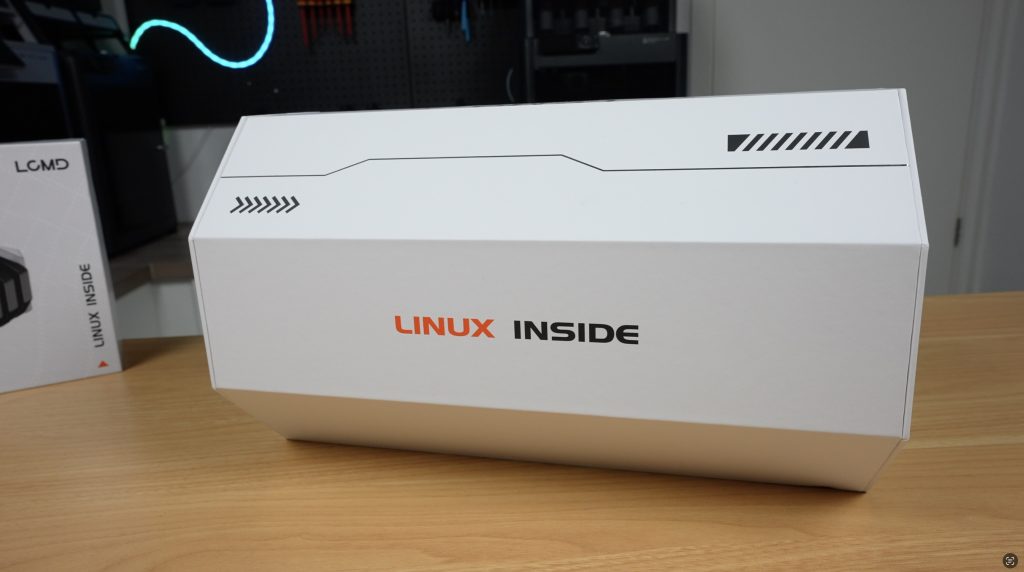
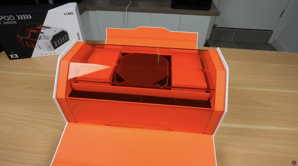
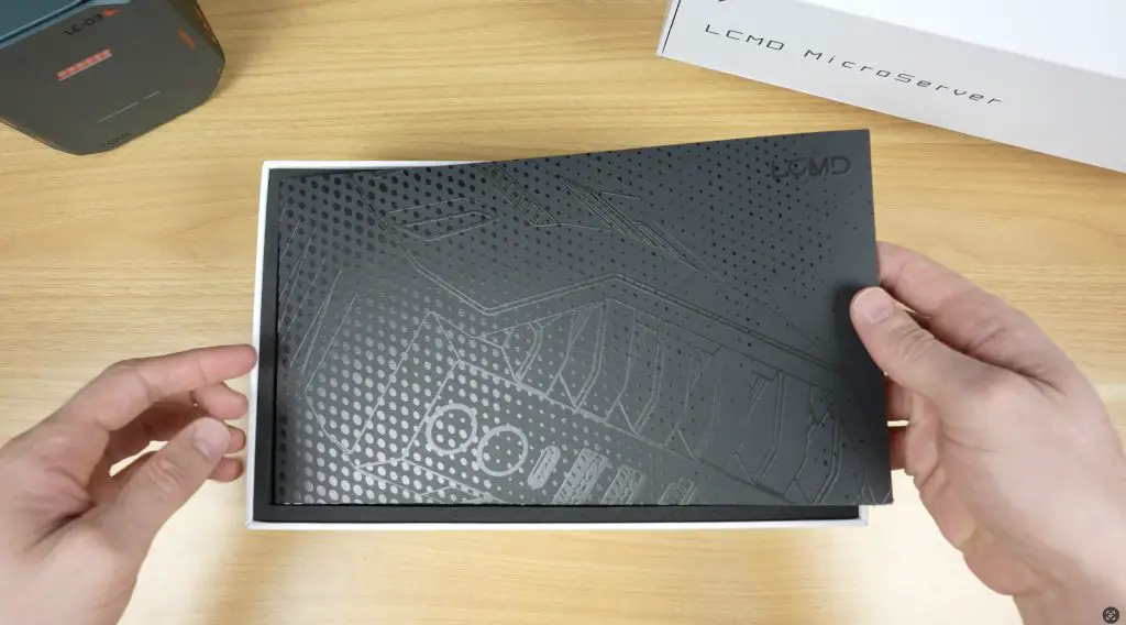
Right from the start, LCMD’s packaging makes a strong impression. This is one of the coolest product packages and unboxing experiences I’ve seen.
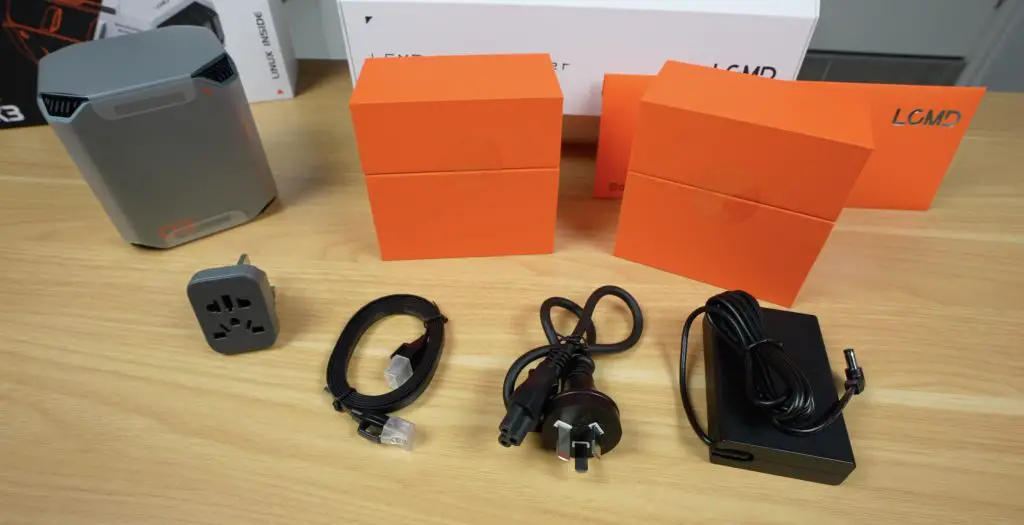
Opening the magnetic flaps reveals an orange acrylic cover, with the LCMD Microserver sitting underneath. Alongside it are two accessory boxes, plus a front sleeve that likely holds documentation. Everything is neatly protected in high-density foam.
Inside the accessory boxes:
Box 1: Ethernet cable and international adaptor for the power supply
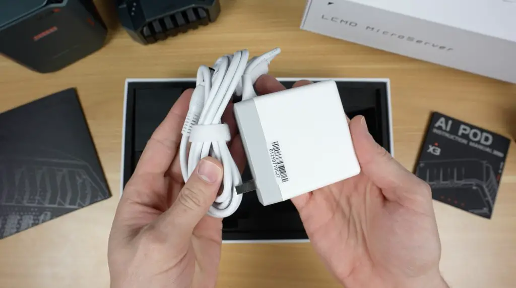
Box 2: 19V 120W power supply (barrel jack connector) and mains lead
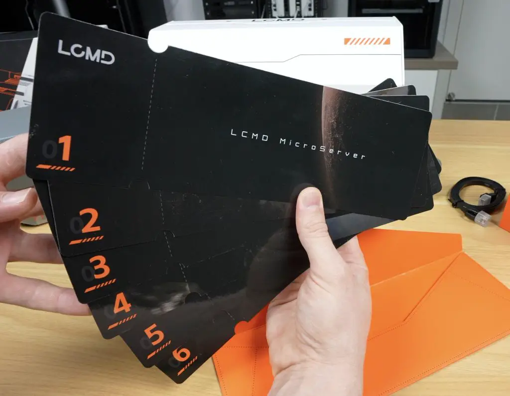
The sleeve contains a set of sequenced instruction cards, a unique and intuitive QuickStart guide.
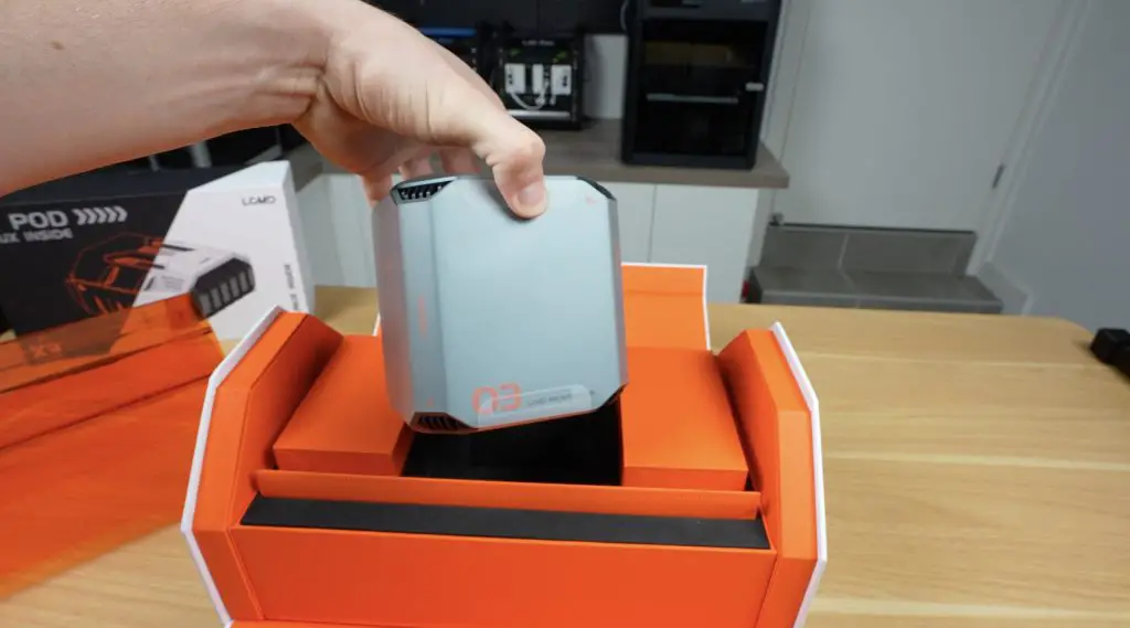
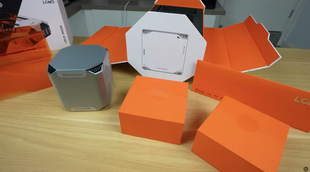
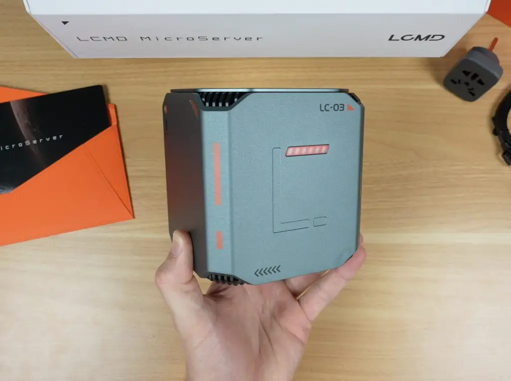
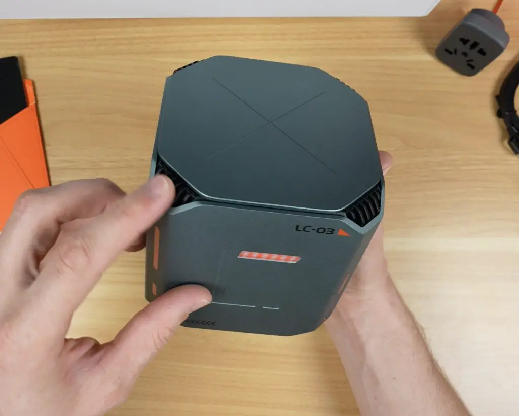
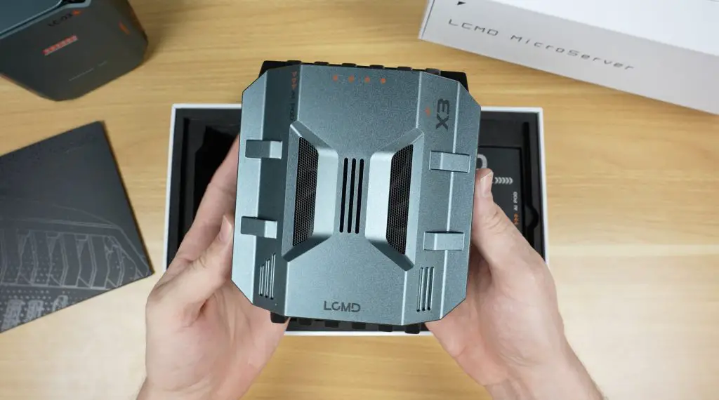
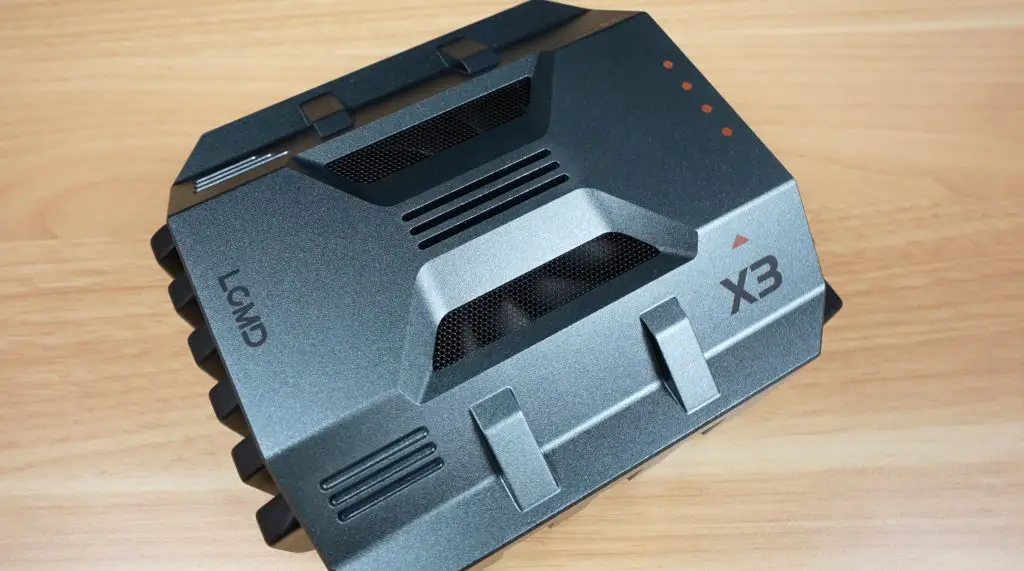
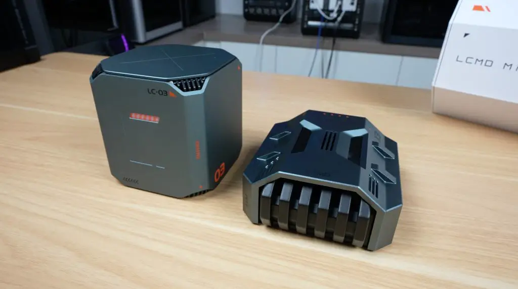
First Look – LCMD Microserver
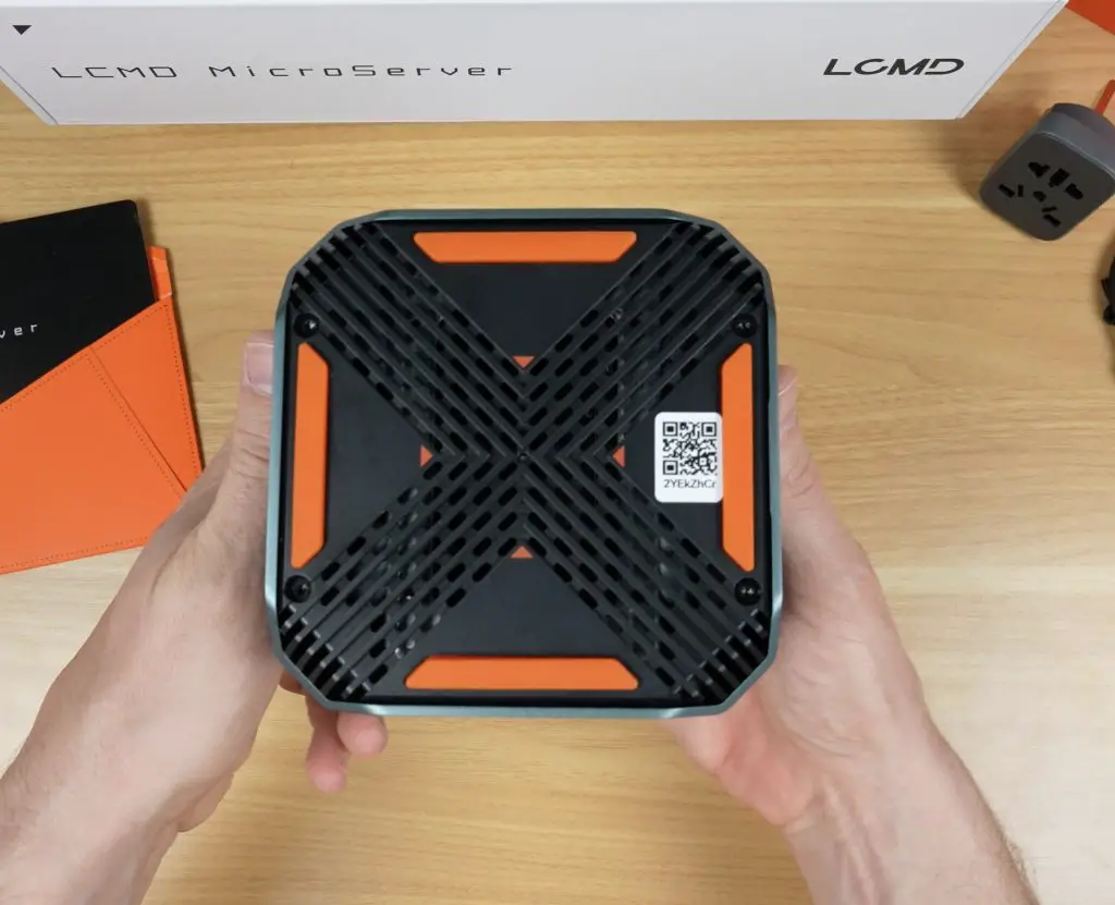
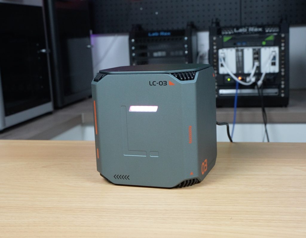
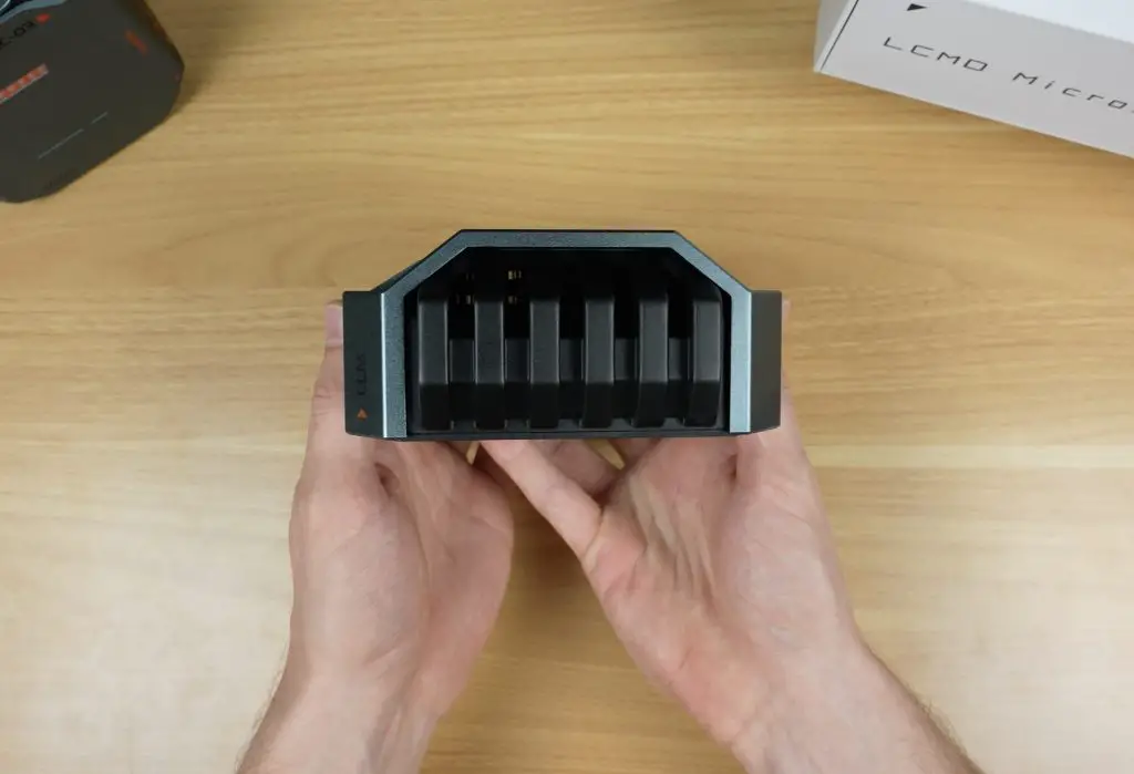
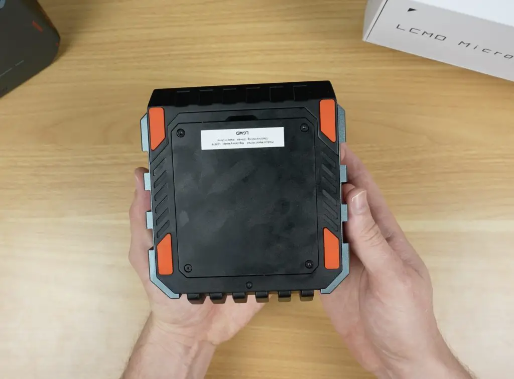
The front and sides are clean with no ports or buttons. On the top we’ve got some ventilation holes on each of the corners. On the bottom we’ve got a large ventilation grill with some orange rubber feet.
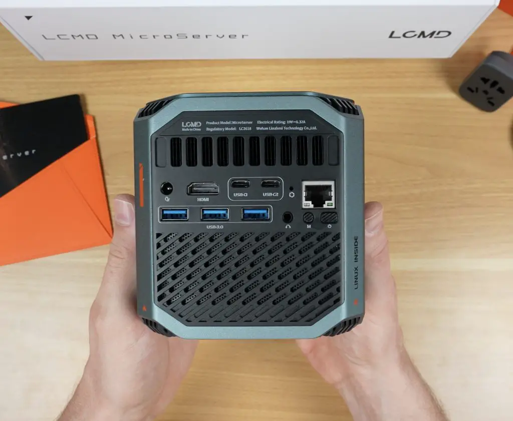
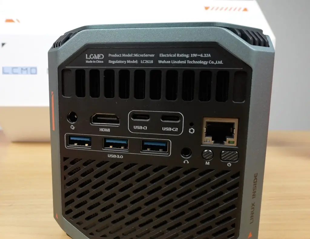
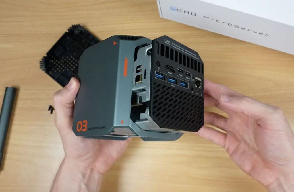
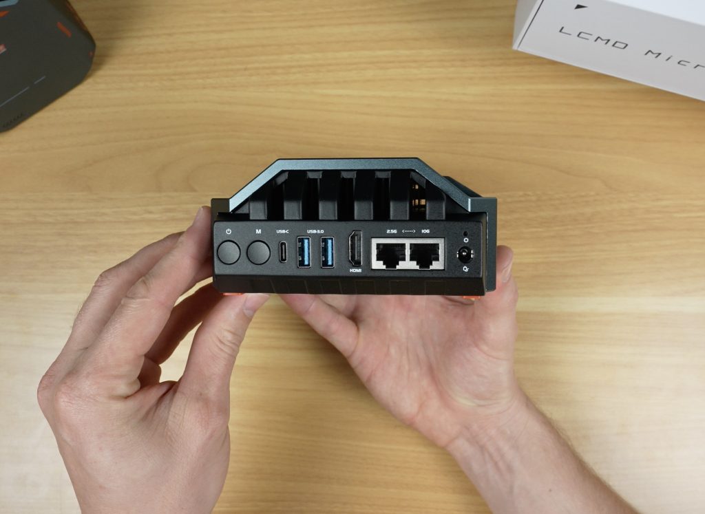
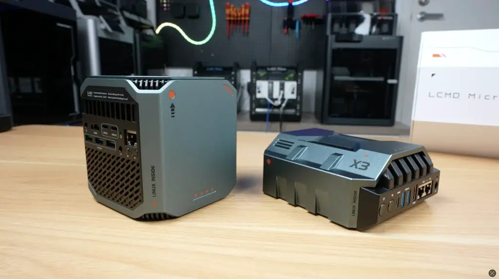
On the back we have all the ports, which are clearly labelled:
Power input
HDMI 2.1 port
Two USB 3.2 Type-C ports
Three USB 3.0 ports
Audio jack
2.5G Ethernet port
Mode and power buttons
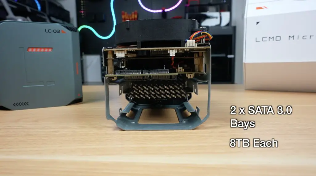
Above the ports are vents for the CPU heatsink; below is an open grill likely for the drive bays. Speaking of drive bays, internally, the Microserver can house two 2.5″ drives and two M.2 NVMe drives.
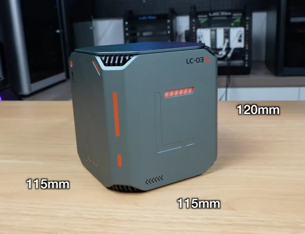
The build quality is excellent, it’s got grey aluminium panels, solid construction, and an orange-and-white futuristic style. It’s also compact at 115mm × 115mm × 120mm.
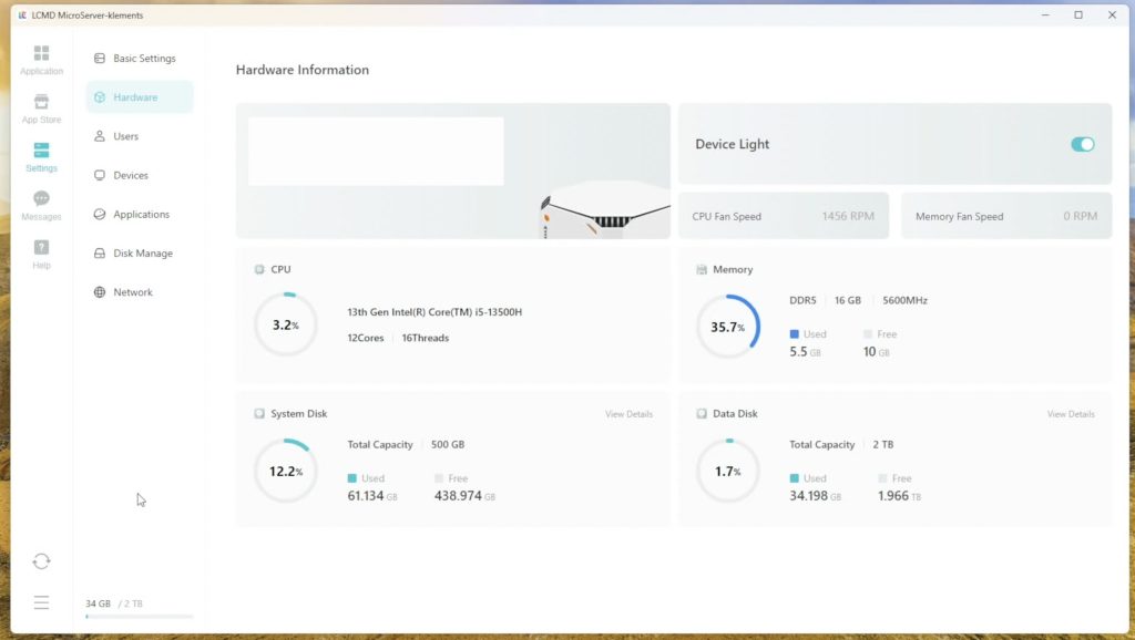
Hardware Specs
Inside, the Microserver runs on an Intel Core i5-13500H. This is a 12-core CPU (4 performance cores up to 4.7GHz, 8 efficiency cores up to 3.5GHz) with Intel Iris Xe graphics (80 execution units at 1.45GHz).
Four additional M.2 2280 slots – up to 64TB (with 16TB drives)
Two SATA 3.0 bays – up to 8TB each
Realistically you could install about 20TB without spending a fortune. It also has WiFi 6E via an Intel AX210 chip.
The enclosure slides out the back after removing two sets of four screws from the bottom, giving access to the internals for upgrades. My only complaint with this process is that the bottom uses Torx screws, while the retaining bracket uses Philips head screws. It would be nice if they were consistent.
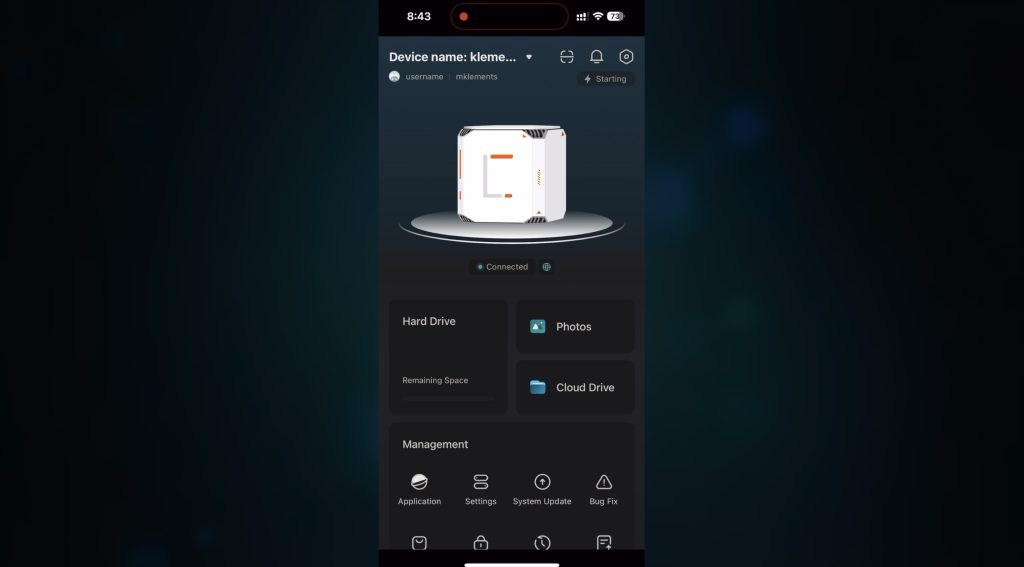
Software and Setup
Booting the Microserver was where I was most impressed. Many products have great hardware but fall short in software, but that’s not the case here.
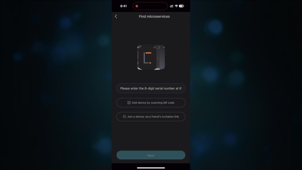
After plugging it in, you install LCMD’s mobile app. The Microserver runs LCOS (which is Debian-based). Setup takes under 5 minutes, and the system automatically configures encrypted remote access (NAT traversal, like Tailscale), so no port forwarding or network tweaking is needed.
There’s also a desktop app for PC and Mac, which lets you:
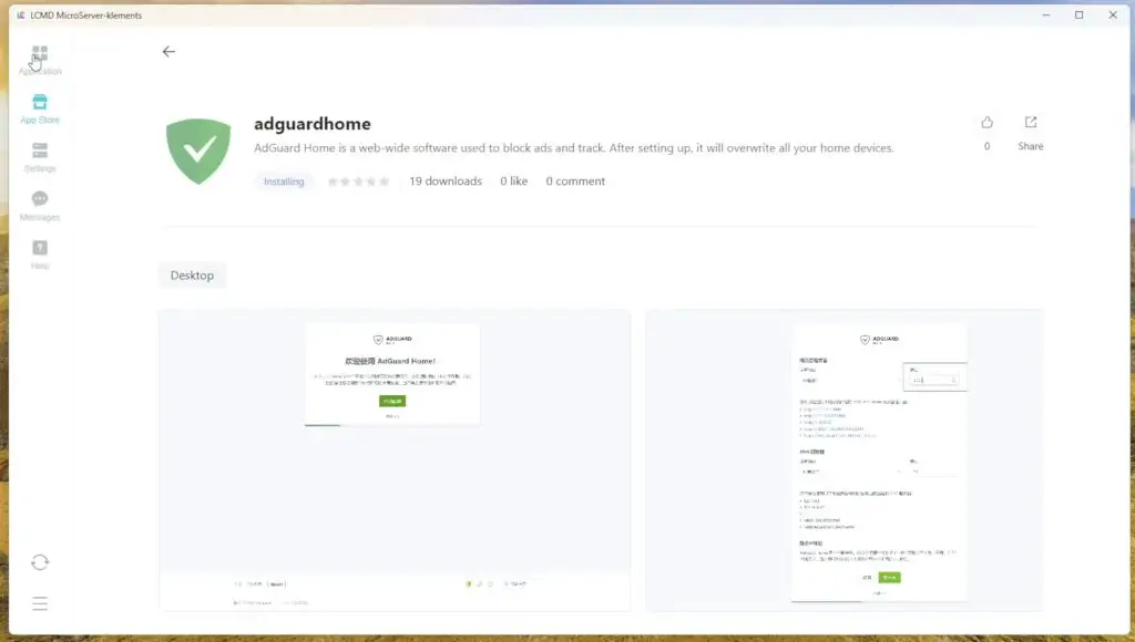
Manage storage pools and permissions
Install over 1,000 available pre-configured apps (including Jellyfin, Nextcloud, Git servers)
Adjust settings
View and manage media
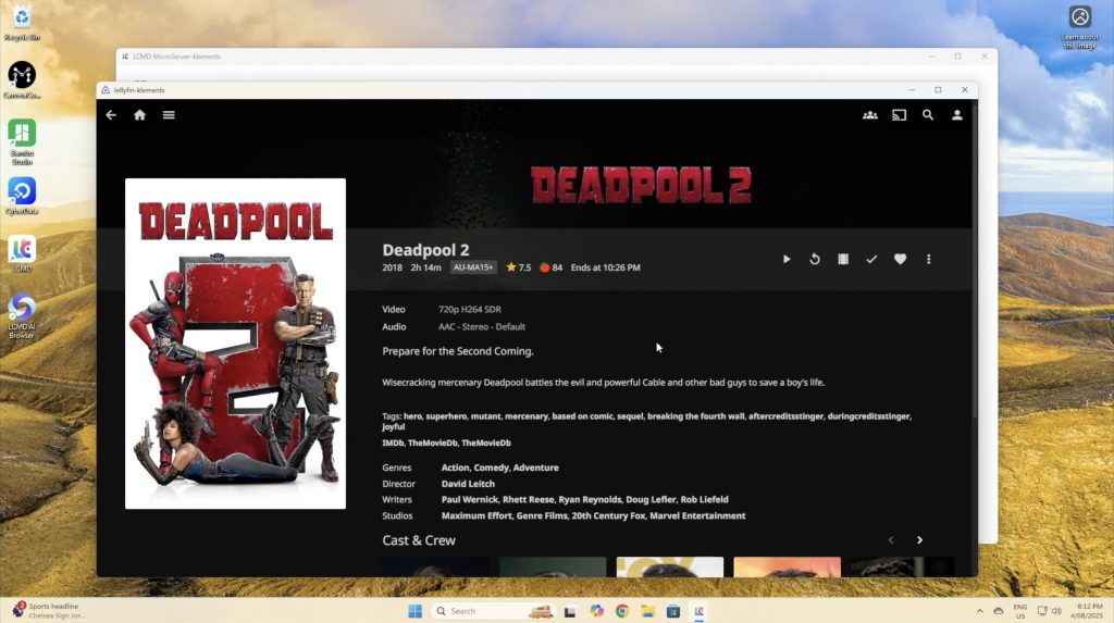
My first test was with Jellyfin, and this installed instantly without advanced setup.
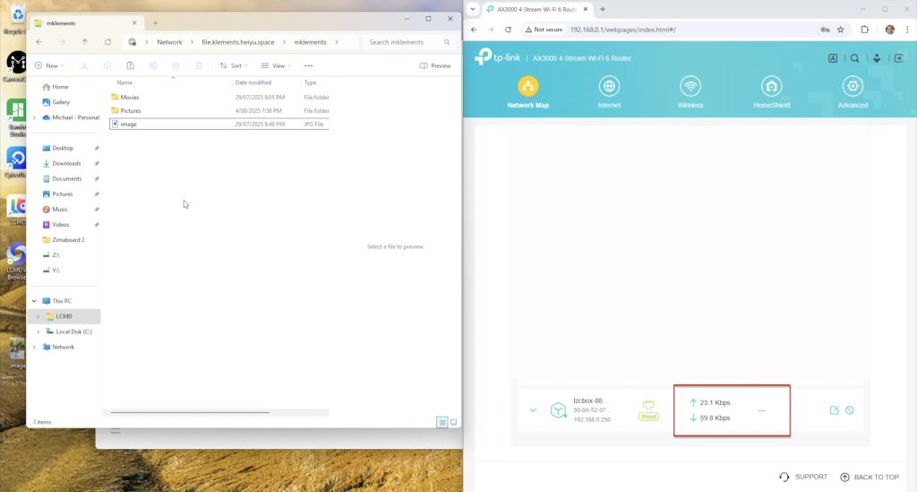
You can also share files over your network with SMB or AFP like a traditional NAS.
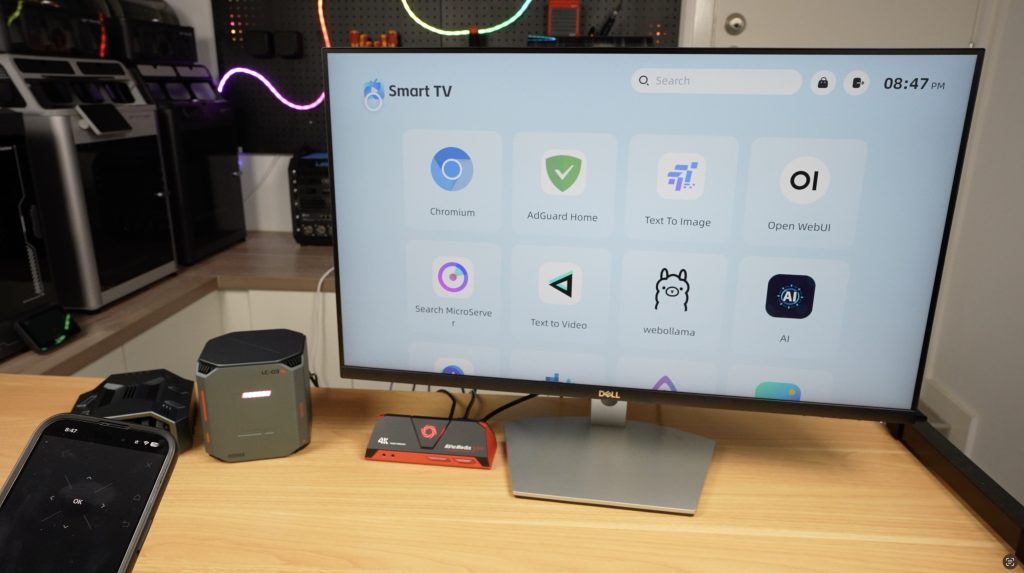
The Microserver can act as a smart TV when connected to HDMI, with your phone as the remote. This allows you to watch media content, look at files and photos and even use some of the AI features will get to with the AI Pod.
The AI Pod, Adding an AI Brain To The LCMD Microserver
The AI Pod is an add-on for the Microserver that adds serious machine learning power. Unlike the Microserver, it can’t run on its own, it must be paired with the Microserver.
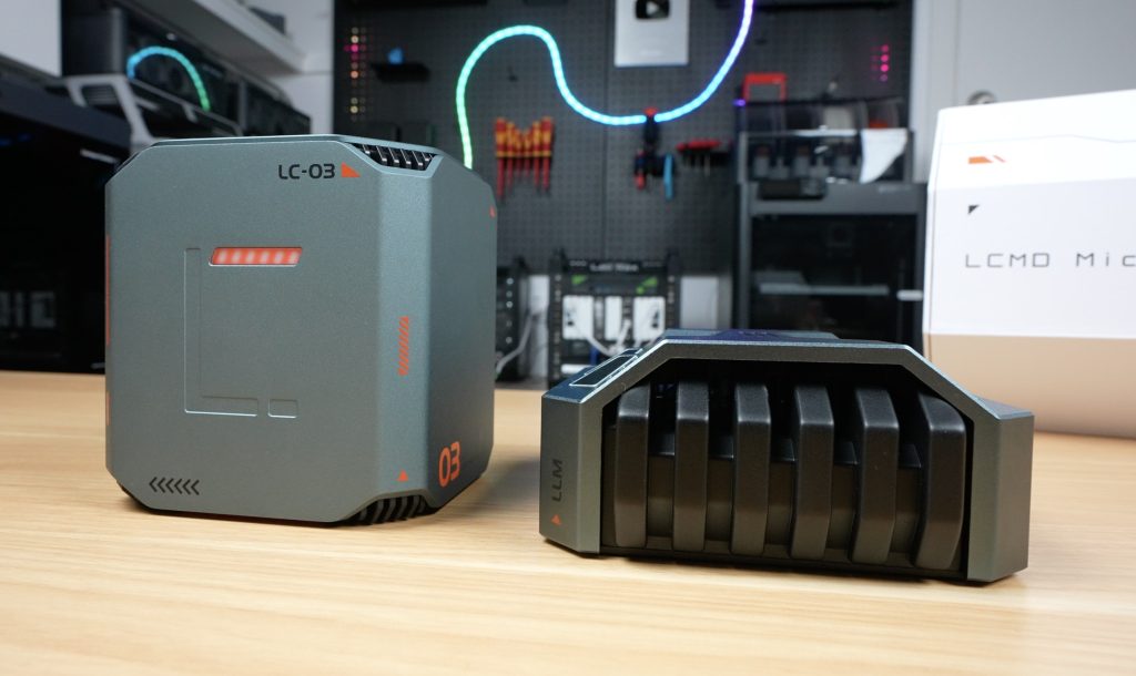
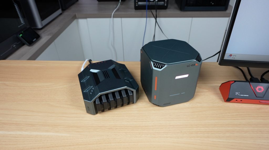
Packaging is again premium, with a foam pad and the device beneath. The AI Pod’s design feels like something from a sci-fi movie. I think it looks a bit like a building from theold PC game StarCraft – I might be showing my age with that comment.
Included with the AI Pod: instruction manual, 12V/96W power supply (my unit was white, but the production one will be black).
Ports and Hardware
Taking a look around the AI pod, the front is actually a ventilation grill and you can actually see through to the back of the enclosure. The two sides are solid. The top has a fine ventilation mesh and the bottom has a removable cover plate.
Like with the Microserver, the ports are all at the back:
Power & mode buttons
USB 3.2 Type-C
Two USB 3.2
HDMI 2.1
2.5G Ethernet
10G Ethernet
Power input
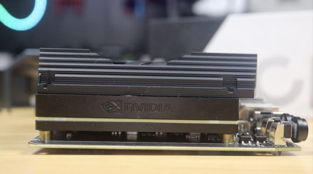
The 10G port is due to the Nvidia Jetson AGX Orin development board inside – not a custom board.
Styling is designed to match the micro server so it’s the same grey aluminium housing with black accents. I think the pair look really cool together.
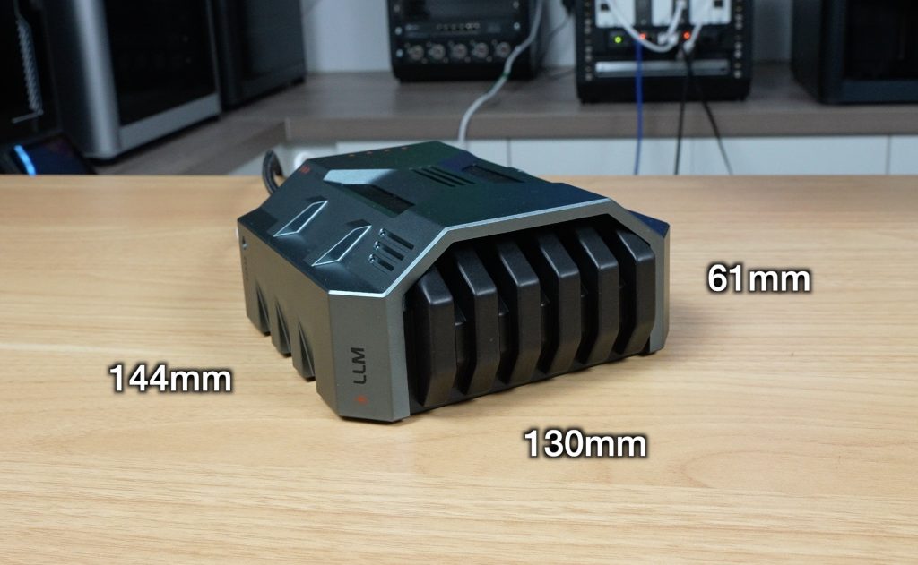
The AI Pod has a slightly larger footprint than the Microserver, measuring 130mm x 144mm but it only stands 61mm high so it might look a bit smaller.
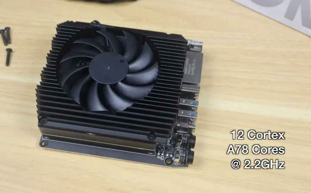
The Jetson Orin board has an Arm CPU featuring 12 Cortex A78 cores that can run up to 2.2GHz and an NVIDIA GPU with 2048 Cuda cores, 64 Tensor cores and 64GB of LPDDR5 video memory. This adds an impressive 275 TOPS of processing power to the Microserver while only drawing around 30-60W.
So this allows you to decode a single 8k30 stream of H.265 video or up to 22 streams at 1080P30. Or it can handle encoding two simultaneous 4K60 H.265 streams. But besides it’s powerful encoding and decoding abilities, it’s main function is to add the ability to run your own AI models locally.
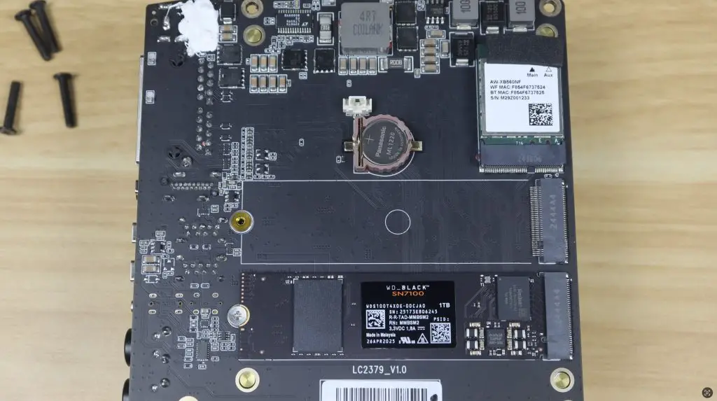
Internally it’s also got a wifi 6 module and a 1TB WD Black NVMe ssd as the OS drive. It’s got a second drive bay but at this stage I don’t think you really need to use it on the AI Pod.
AI Features in Action
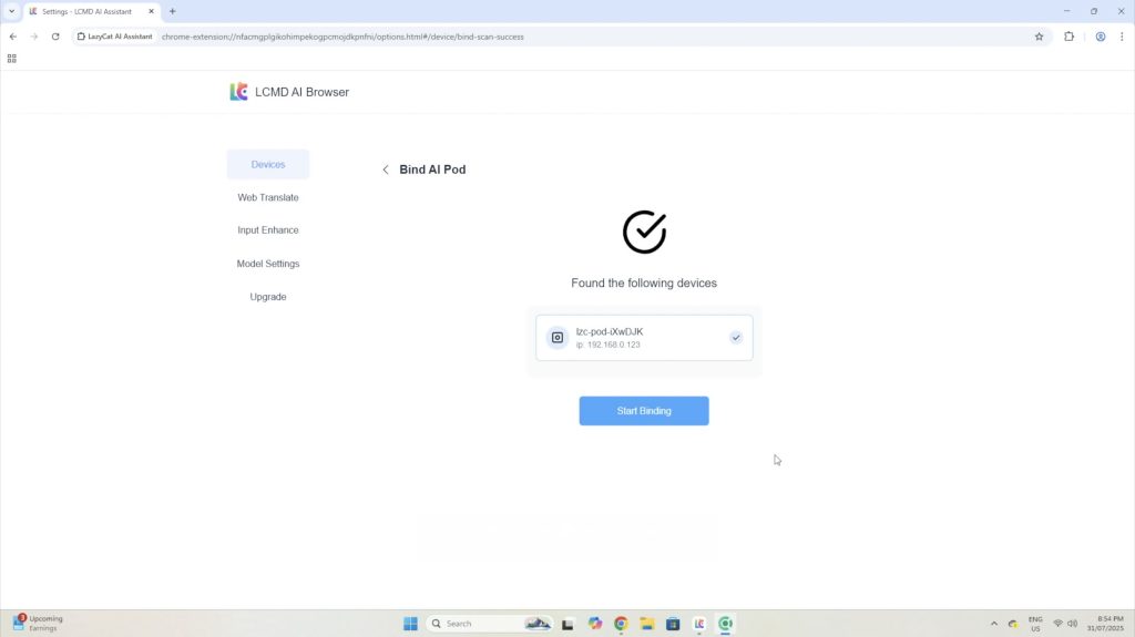
Pairing the AI Pod is easy via a separate desktop app.
With this added, you now have access to some AI based apps that’s take advantage of the pods processing power, so you can do things like image and video generation locally.
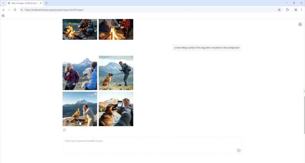
I tried out image generation first. My first test prompt was “a man taking a photo of his dog with a mountain in the background”.
The first test prompt worked quite well. The first and last images aren’t quite what I was going for but the other two are quite good.
You can also do different image styles like generate cartoon images. The next prompt I tried was “cartoon style image of a man reviewing the latest iphone in his home office”.
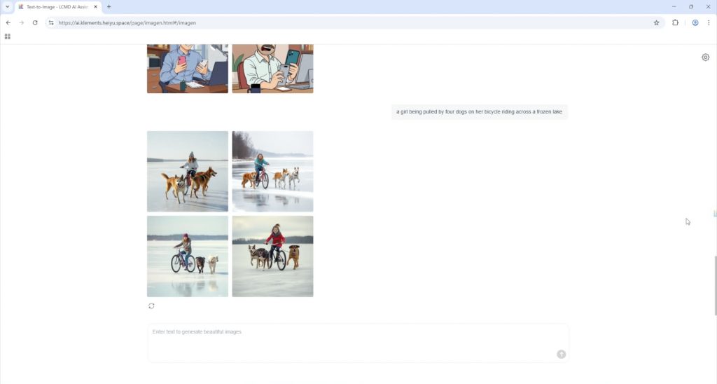
Lastly, I trieda prompt that I thought would be a bit more difficult “a girl being pulled by four dogs on her bicycle riding across a frozen lake”.
This even worked reasonably well, although this model clearly has a problem with numbers, none of these images have four dogs and this one has two heads.
Next I tried video generation. This works in a similar way to image generation, but takes a bit longer as it has to generate multiple frames.
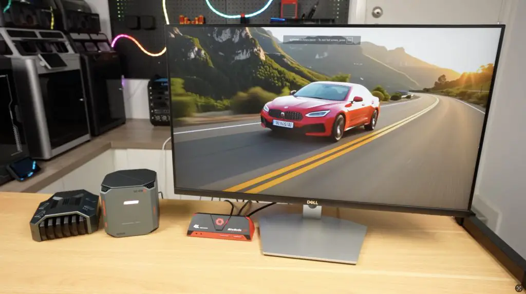
I tried to be quite specific with this prompt “a red sports car driving through a mountain road at sunset”.
This came out much better than I expected. It’s not amazingly realistic but it is really impressive for a video generated in a minute or two on a local piece of hardware drawing under 100W. You can see this video and the second example video in my Youtube video at the begining of the post.
The second prompt I tried was “a cat looking out the window while it is raining”.
This one also come out quite well.
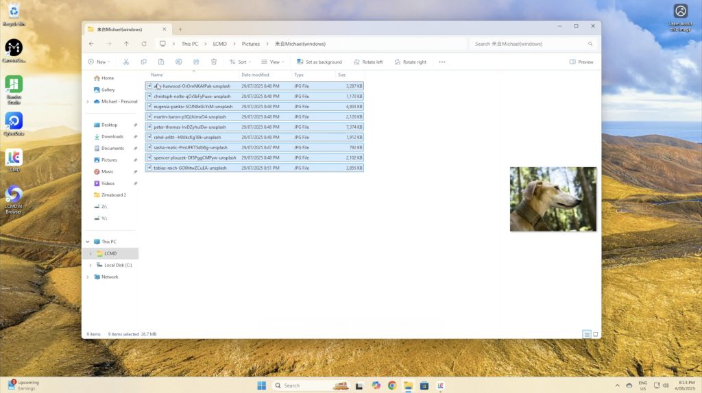
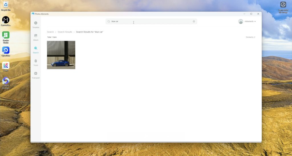
One of the features that I really like is the added search funtionality to your photo albums. You can give it very specific queries and in my small sample libary its very accurate.
This is a really useful feature if you’ve got thousands of photos and you don’t recall when you took a particular photo but you remember a small detail in it.
There are also a whole lot of other AI based features that I could make a separate video on but some of the useful ones are the ability to translate text locally in the browser, and you can even run a local language model similar to ChatGPT.
Pricing of the LCMD Microserver and AI Pod
Since this product is going to be crowd funded through Kickstarter before becoming a retail product, the is a special “launch price” for each product and then an eventual MSRP.
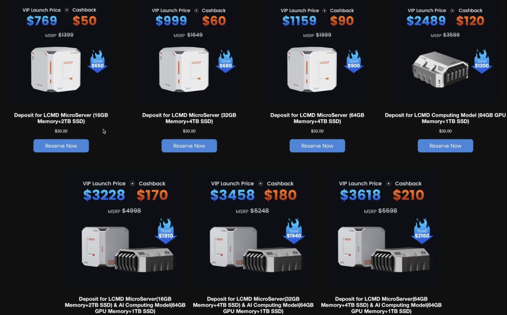
Bottom Model Microserver (16GB/2TB): $769 launch, RRP $1400
Top Model Microserver (64GB/4TB): $1159 launch
AI Pod: $2489 launch, RRP $3600
Combo deals: $3228–$3618 launch pricing
My feeling on the Microserver pricing is that the launch prices are quite fair but the RRP prices are higher than I’d expect. And the AI Pod seems quite expensive, even at launch price. They do both use more premium WD Black drives and Crucial RAM, so they haven’t cut corners with no name brand components but the AI Pod can’t be priced near where a used A4000 or 3090GPU would be a similarly priced as these would be a more powerful option. If they do then the AI Pod will have to seriously prove its worth in software.
Privacy and Transparency
One of the concerns people are probably going to have with a product like this, is that it is running a lot of preconfigured software with very little disclosure on what is and isn’t being shared with the manufacturer, and there is some good and bad news here.
The system is running a custom OS with quite a few proprietary layers and while that makes it capable and offers a lot out of the box, at this stage there is limited transparency on exactly what its doing in the background.
I compiled a long list of questions and spent quite a lot of time talking with LCMDs developers in trying to determine what information they have access to and how this information is used and I’ll try present a summary in the best way that I can. The full list of questions and answers is provided in the next section below.
The LCMD microserver is designed with decentralisation and privacy as a core selling point, which means that users naturally want to bring as much in-house as possible. But on the flip side, LCMD are also trying to make the system as user friendly and easy to use as possible, which they have really nailed. The platforms custom client app enables powerful features that just work, you don’t need to be a wizz with docker containers or have any advanced networking knowledge to get the Microserver up and running. Most people aren’t able to set up remote access to their home networks in a secure way, so there is a balancing act here which they’re trying to navigate.
From what I’ve found through testing and in talking to the developers, the server prioritises direct peer-to-peer communication using asymmetric encryption, and the private keys are stored locally on the device. If both devices can be reached via hole punching then traffic flows directly peer to peer, this falls back to relayed traffic if that process fails – quite similar to Tailscale.
For more advanced users that want a bit more transparency and control, you can also set up your own NAT traversal through Headscale – which is one of the preconfigured apps it offers.
Local storage is also encytped and the encryption keys are again stored locally on the device, so don’t forget your password or your data will be lost.
The server only requires internet access for the initial setup or app installation. You obviously also require an internet connection for remote access after this but if you don’t need remote access and the initial setup is all you require then you can isolate the system from the internet and it’ll continue to function on your local network.
At the very extreme end, the Microserver’s BIOS is also unlocked, so if the software isn’t for you, then your can install your own OS on it if you’d like to. Although for this particular product, the software is a large part of the user experience – so it probably doesn’t make much sense to do so.
With all of that being said, the Microserver still uses proprietary software like its own VPN protocol, which unlike open standards like WireGuard, hasn’t been independently auditied. It’s dependency on a central server is limited but not zero, and although you could potentially configure it yourself to be zero, I wouldn’t say that the system is 100% trustworthy, but it’s about as close as you can get without them making the whole software package open source too.
Questions Asked To Developement Team & The Answers Received
Here’s a list of questions that I compiled and asked their Developement team along with the answers I received back. Due to the language barrier, some questions were reworded or repeated in different ways and translations were required in both directions, so I have summarised the questions and answers here while trying to maintain their original intention.
Q1 – What is LCMD’s networking approach, it appears to be similar to Tailscale?
Answer:
LCMD’s direct connection mode works in a similar peer-to-peer way. In most cases, all traffic is sent directly between devices. In extreme situations (like multiple layers of NAT4), they provide a completely free relay server with 8 Mbps bandwidth and full end-to-end encryption. Users can also self-deploy their own relay server, which maximizes decentralisation.
Q2 – How can users verify that direct connection traffic isn’t passing through LCMD’s servers?
Answer:
Two ways:
Technical validation – Advanced users can use tools such as Wireshark to check if the inbound/outbound IP corresponds to their home broadband’s public IP.
Business reality – Routing all traffic through their servers would be financially unsustainable given bandwidth costs.
They emphasised that direct connection is built on a decentralisation philosophy to improve performance and privacy at no cost.
Q3 – How are encryption keys handled, and can LCMD access these keys?
Answer:
There are two types of keys:
Initialization / license verification – Bound to the motherboard; requires a connection to the official server for registration during initial setup.
Device communication keys – Public/private key pair generated locally on the Microserver. LCMD’s official servers do not have access to your private key, meaning only authorised users can connect.
Q4 – Is the relay/STUN service open source or self-hostable?
Answer:
LCMD currently allows self-deployment of the relay server, but STUN is not fully open yet. They plan to follow up on this. As a temporary solution, the LCMD Official App Store has Headscale available for one-click installation so users can self-deploy.
Q5 – Why is there a desktop app instead of just a browser dashboard?
Answer:
While browser access is possible via a domain name, the desktop app creates a TUN virtual network interface, enabling advanced networking features.
Benefits include:
Secure remote access without needing to set up public IPs, NAT traversal, or firewall rules.
Works out-of-the-box for non-technical users.
For advanced users, browser access remains available, but the desktop client delivers a smoother and more secure experience.
They added that a client app can do things browsers can’t, like:
Auto-mounting a cloud drive to the system file browser.
Uploading to the cloud drive app even after the window is closed (client must still be running).
A no-GUI client is also available for more technical users.
Q6 – Does the device need the internet to operate?
Answer:
Internet is only required for initial setup and when installing apps from the LCMD store. In all other cases, it can operate fully in local-only (LAN) mode without internet.
Q7 – Can I access the device via IP address directly?
Answer:
Yes — they offer a LAN port forwarding tool for this purpose and can provide further documentation.
Q8 – What is LCMD’s overall decentralization approach?
Answer:
LCMD was designed with decentralization in mind so users can build and access their own cloud services without relying on centralised infrastructure.
If the network has a public IP or favorable NAT, connections go directly between devices.
Benefits: better privacy, full use of home bandwidth, and stable decentralised performance.
If direct connection is impossible, free relay services (end-to-end encrypted) are provided.
Advanced users are encouraged to self-host network penetration services. A “Network Penetration Service Setup Guide” will be released within a year.
Q9 – Is the device locked to LCMD’s OS?
Answer:
No — the BIOS is open, and users can install another operating system if desired.
So that’s the LCMD Microserver and AI Pod – a seriously powerful private cloud and AI edge device combo that’s really easy to set up and use.
Performance is great, the user interface is very well polished and it’s AI features are genuinly helpful, not just for party tricks. I do think LCMD could benefit from being very open about what’s running under the hood, especially for a product designed around privacy and user control, but the same could be said for most cloud or data storage companys.
Let me know what you think of the LCMD Microserver and AI Pod in the comments section below and if this is something you can see yourself using for your homelab or personal cloud.
Here’s a link to their prelaunch page where you can join the waiting list to be notified of their official launch on Kickstarter. As with the other crowd funded products that I’ve reviewed, keep in mind that crowdfunded projects carry some level of risk and that there is no guarantee that the final product will live up to the promises made in the campaign.
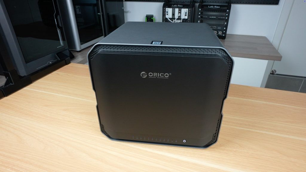
Today we’re diving into a NAS that’s built for much more than simple home backups, the CyberData CF1000 by Orico. This is the flagship model from their newly released CyberData NAS series, which includes eight different configurations featuring a variety of CPU, memory, and storage options, all packed into a stylish, unified design.
Orico is a brand that’s long been recognized for its USB storage solutions, enclosures, and docking stations, but the CyberData line marks a bold and serious step into the NAS (Network Attached Storage) market.
Here’s my video of the CF1000, read on for my written review;
Where To Buy The Orico CyberData CF1000
Orico’s CyberData range is currently crowdfunding through Kickstarter – Campaign Link
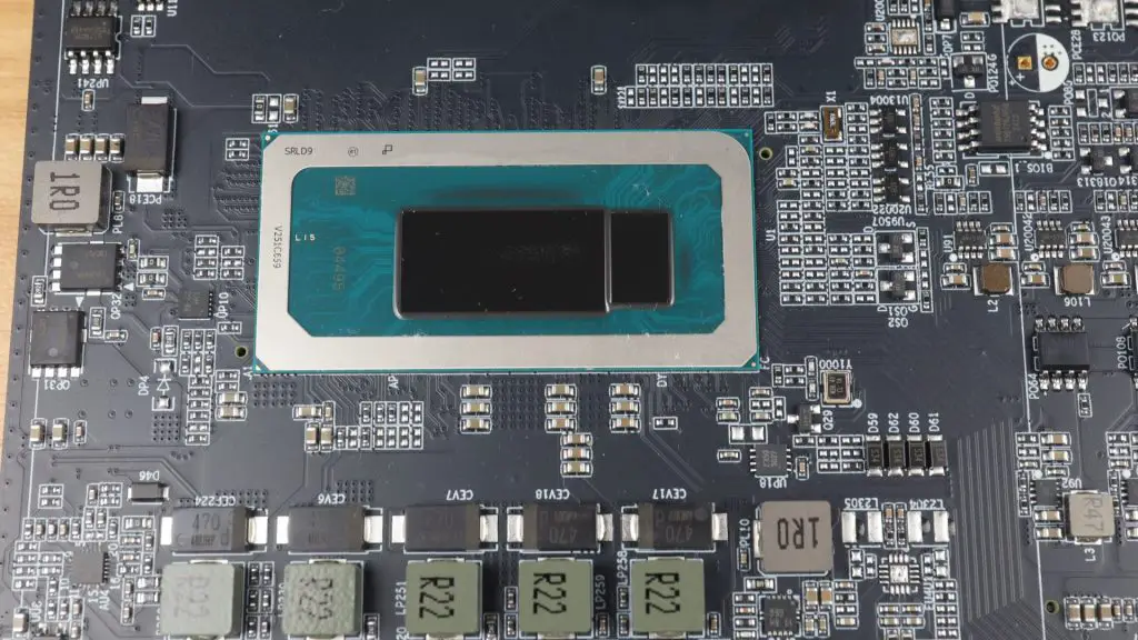
Powering the CF1000 is a 12-core Intel i5-1240P processor with 16 threads,
It also has dual 10G Ethernet ports, and support for up to 256TB of storage. It’s a NAS built with power users, small businesses, and creative professionals in mind.
Let’s start with the unboxing experience.
Unboxing the CF1000
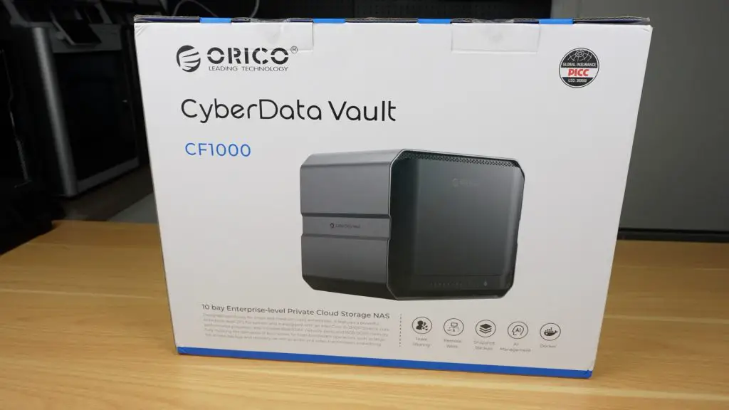
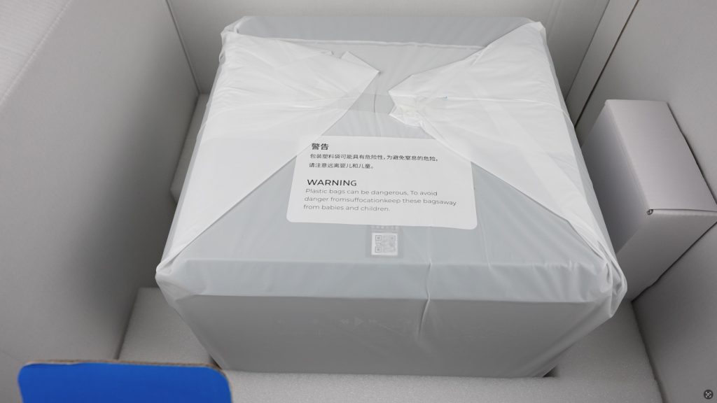
The CF100 is very well protected in it’s packaging, although the box is large for a 10-bay NAS, that’s mainly due to the thick foam padding keeping everything secure.
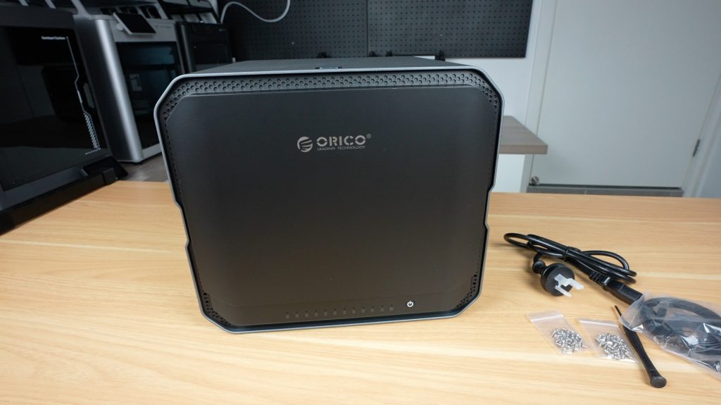
Inside the box, you’ll find:
The CF1000 NAS wrapped in an antistatic bag
A smaller accessory box containing the power cord, screws, screwdriver, two network cables, and a manual
The CF1000 itself looks and feels fantastic. It’s sleek, minimalistic, and well built with a premium solid cast aluminum chassis.
A Closer Look at the Hardware
Front Panel
Behind a magnetic front cover are 10 hot-swappable 3.5” drive bays, arranged in two vertical columns (1–5 and 6–10). Under the drive bays are LED indicators, although these are a bit strangely numbered backwards from 10 to 1, and then we’ve got status LEDs for network and system health.
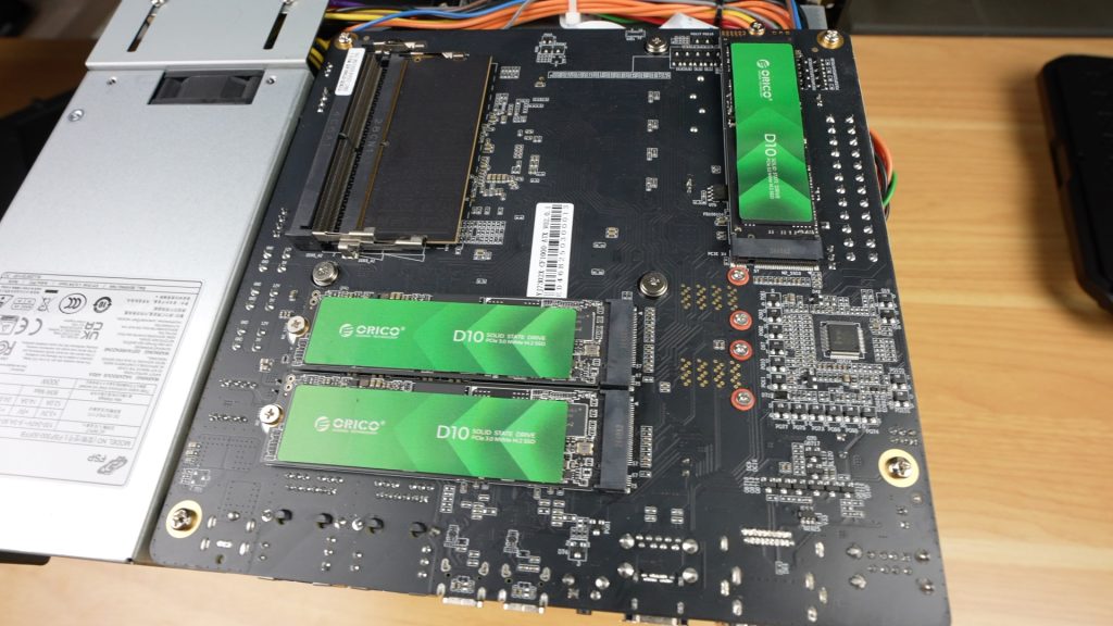
Internal Expansion
Internally, we’ve also got space for:
2 x M.2 NVMe SSDs (for caching or high-speed access)
1 x 128GB NVMe SSD (preinstalled for the OS)
These M.2 drives are easily installable through a bottom access hatch, which is a great feature on the CF1000.
Rear I/O Ports
Around the back, we’ve got;
2 x Cooling fans
2 x USB 2.0 ports
1 x DisplayPort and 1 x HDMI
2 x USB 3.2 (Type-A and Type-C)
2 x USB4.0 (40Gbps capable)
2 x 10Gb Ethernet ports with link aggregation support (up to 20Gbps)
Integrated PSU, so there is no additional power brick required.
CPU and RAM
The Intel i5-1240P is a 12-core mobile CPU from 2022, with 4 performance cores running at up to 4.4GHz and 8 efficiency cores running at up to 3.3GHz. It supports DDR5 memory, Thunderbolt 4, and has 20 PCIe lanes. It’s both powerful and power-efficient, ideal for a NAS setup that’s going to be running 24/7.
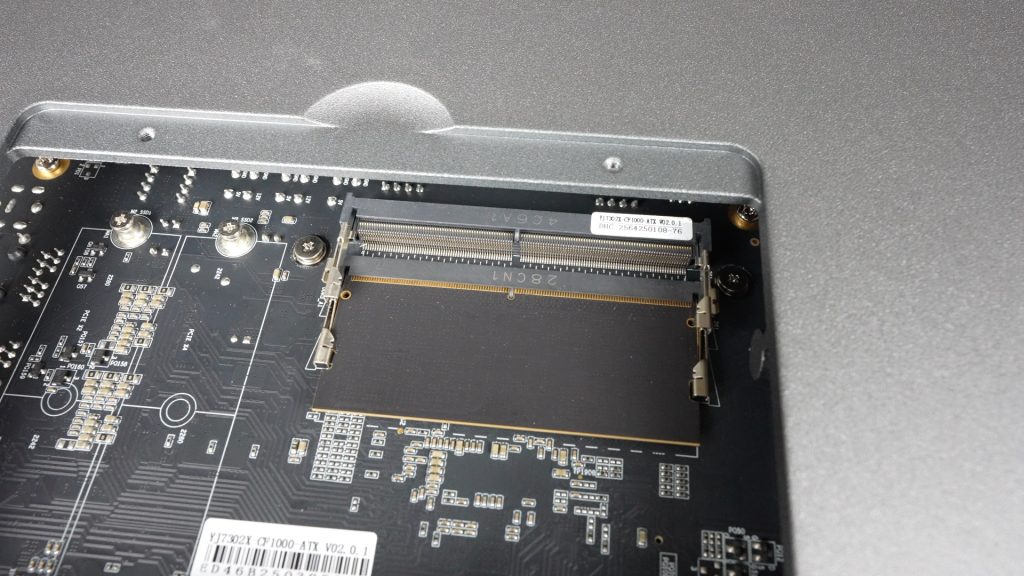
The CF1000 comes with 16GB DDR5 RAM (4800MHz) installed via a single stick, so you’ve got an easy upgrade path to 32GB and it’s expandable up to 64GB in total.
Storage Capabilities
The main storage feature of the CF1000 is obviously the 10 drive bays, but in addition to these we’ve got the two M.2 slots for additional storage or caching. This gives the NAS a total storage capacity of 256TB (10 x 24TB HDDs and 2 x 8TB SSDs) and it supports a range of hardware RAID options including RAID 50 and RAID 60.
10 x 3.5” HDD bays
2 x M.2 NVMe SSD slots
Built-in 128GB SSD for the OS
Up to 256TB of total storage capacity
Hardware RAID support, including RAID 50 and RAID 60
Setting Up The ORICO CF1000
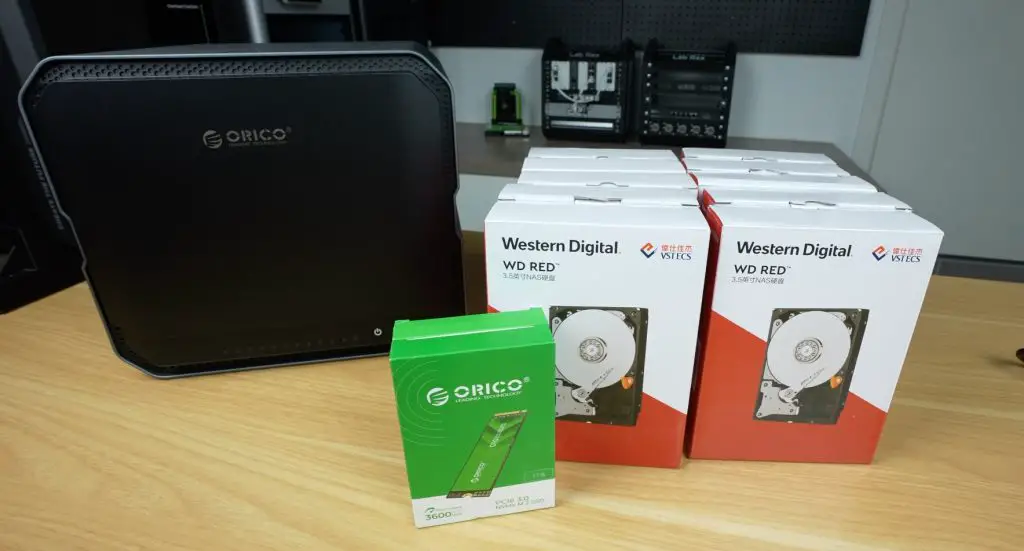
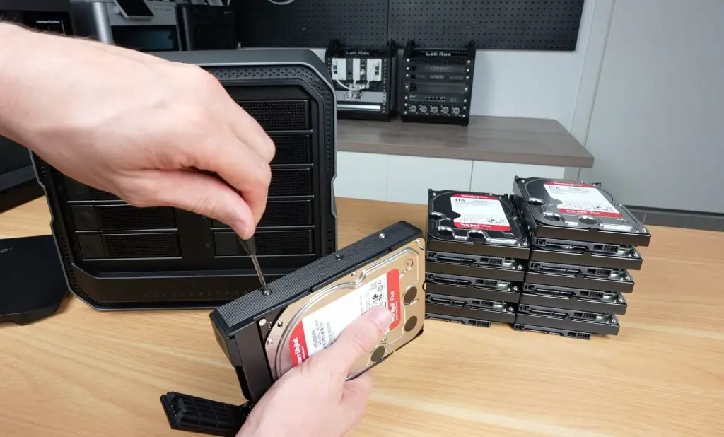
For testing the CF1000, I installed:
10 x 4TB WD Red HDDs
2 x Orico D10 NVMe SSDs
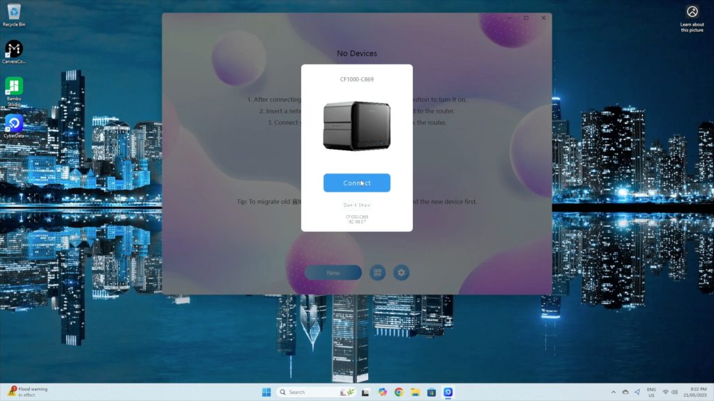
Once powered and connected to the network, the system boots into CyberData OS, Orico’s custom NAS software. Setup is handled through their CyberData client app for PC or mobile.
It’s worth noting that you can’t access the NAS via a standard web dashboard, a feature common to other NAS brands. Hopefully, this will be added in future updates as it’s a bit inconvenient to have to install software to change a feature rather than just going to a web dashboard.
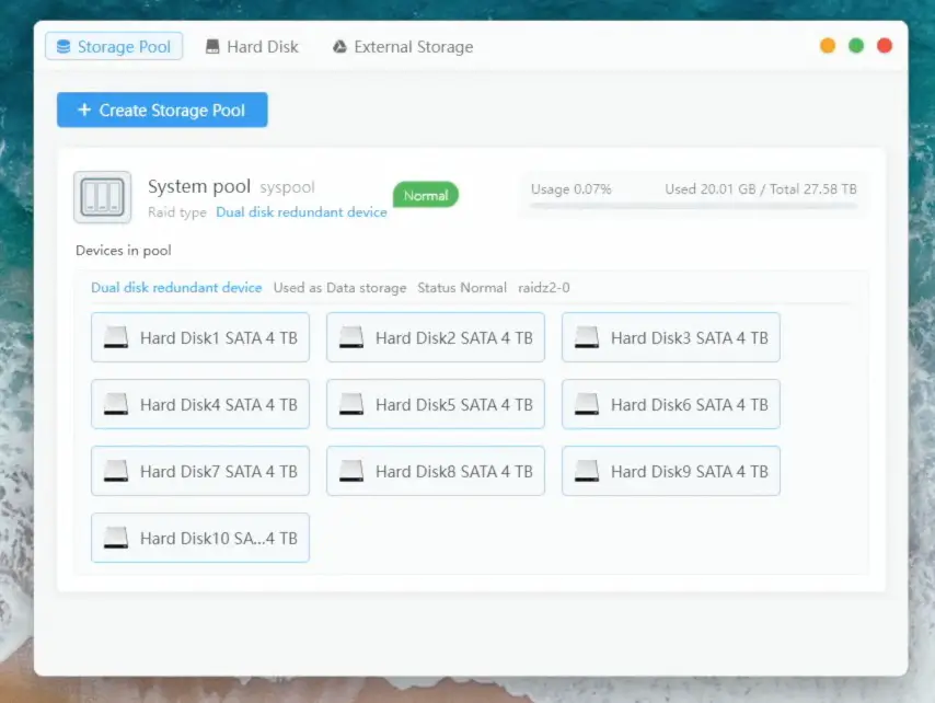
Storage Pool Setup
Once an admin account is created, the software detects the installed drives and allows you to configure your storage pool and RAID level. I opted for RAID 6, which provides 80% usable capacity (32TB) and tolerance for up to two simultaneous drive failures. It does reduce write speeds due to dual-parity overhead, which also gives us a chance to test how the CPU handles this load.
Setup was really quick, taking only a few minutes.
CyberData OS Interface & Basic Features
CyberData OS feels intuiative and easy-to-use with its Windows desktop-style interface.
Key features include:
User permission management
Samba, FTP, WebDAV, DLNA, and Time Machine support
AI-based photo sorting
Movie/TV show metadata fetching
Offline video transcoding
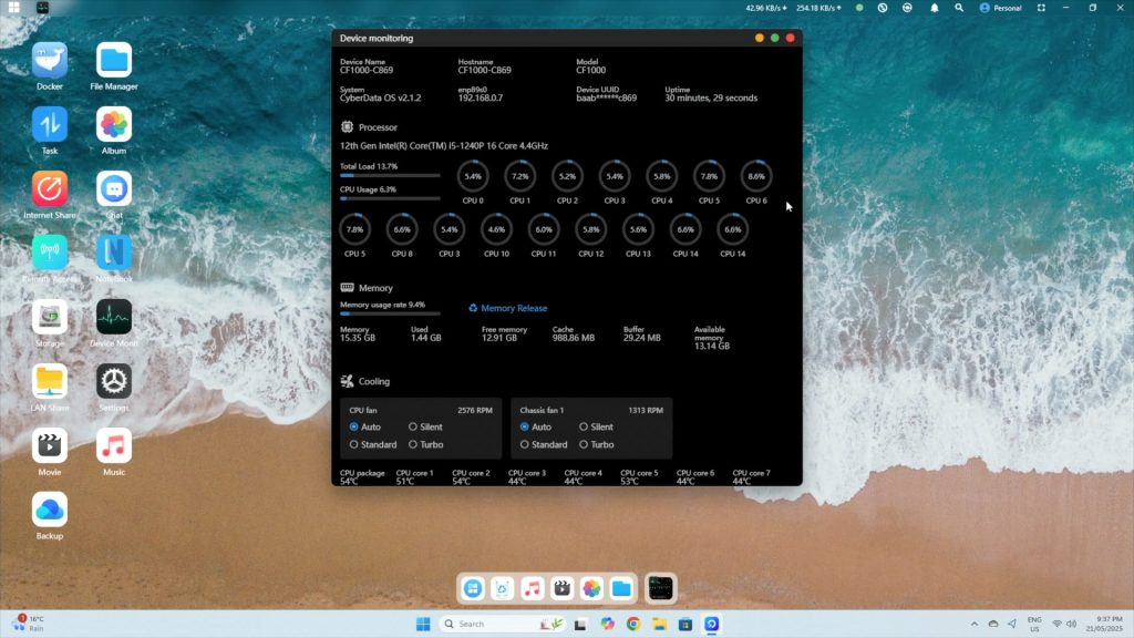
Under the system monitor, you can view:
CPU stats (12 cores, 16 threads)
RAM usage
Drive and CPU temps
Fan controls (auto, silent, standard, turbo)
The storage panel shows:
System storage pool with usable space (~27.5TB for my RAID 6 configuration)
Drive SMART details
Storage Performance As A NAS
To test how the CF1000 performs as a NAS, I created a second storage pool on the NVMe drives to test raw speed differences.
Note: While NVMe can be used for caching, ZFS already handles asynchronous writes effectively using RAM, so there’s not much benefit in small office or home scenarios. CyberData OS warns you about this when you work through the drive pool setup process.
Automated Benchmarks
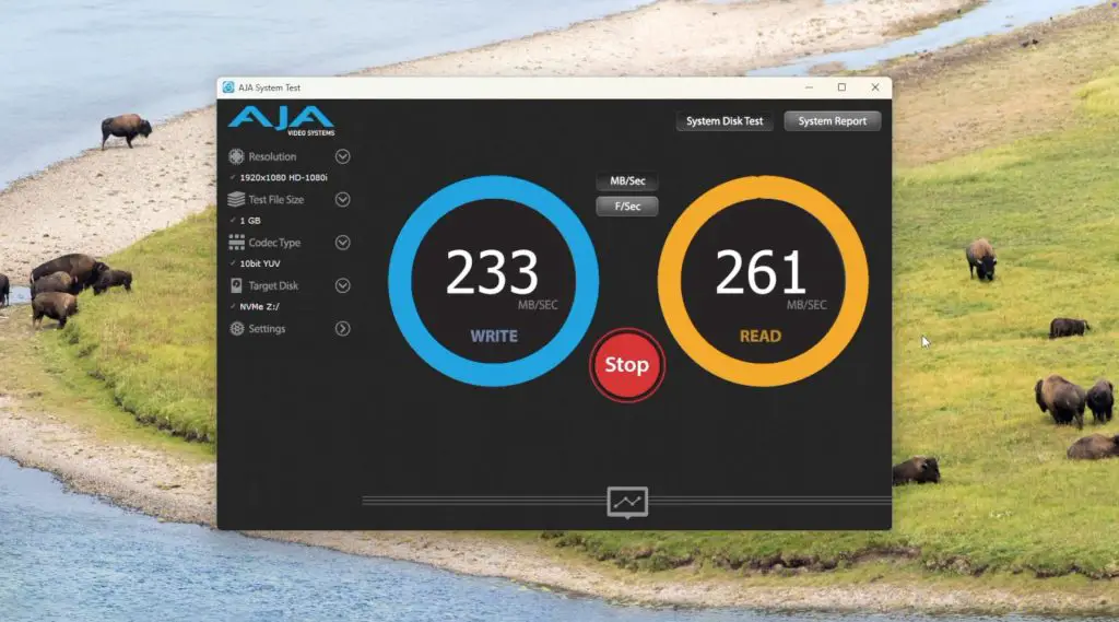
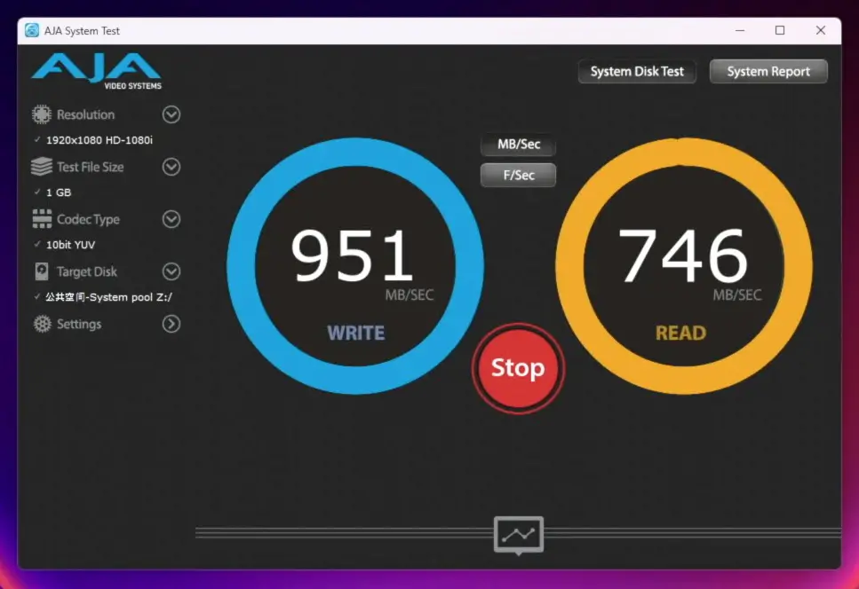
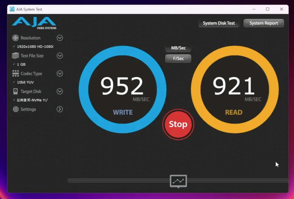
I started out by running some automated tests using AJA System Test over the 10G network connection.
64GB file: Consistent writes, reads around 830–840MB/s
NVMe Storage Pool:
1GB file: ~950MB/s writes, ~900–950MB/s reads
16GB file: ~940MB/s writes, ~920MB/s reads
64GB file: ~920MB/s writes, reads just under 900MB/s
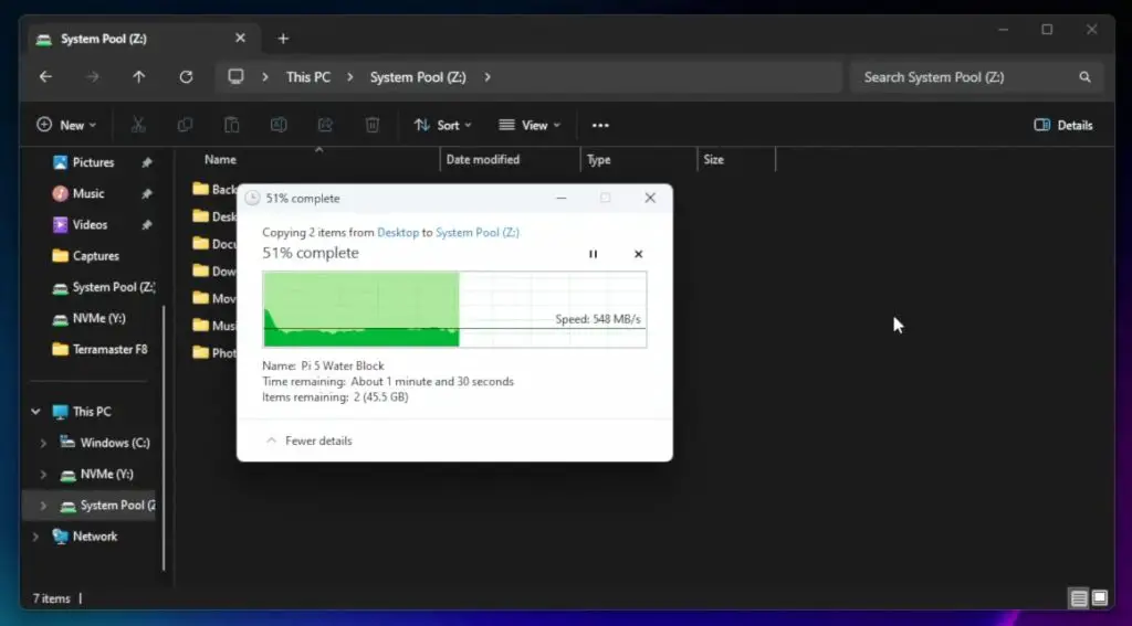
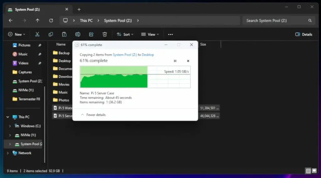
Real-World Transfers
I then also ran some realworld tests transferring two large video files totalling around 90GB to and from each volume, again over the 10G network connection.
HDD volume: ~540MB/s write, ~1GB/s read
NVMe volume: >1GB/s write, ~1.1GB/s read
Thermal Performance
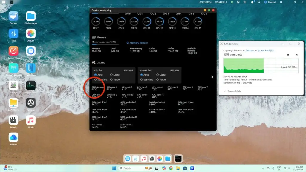
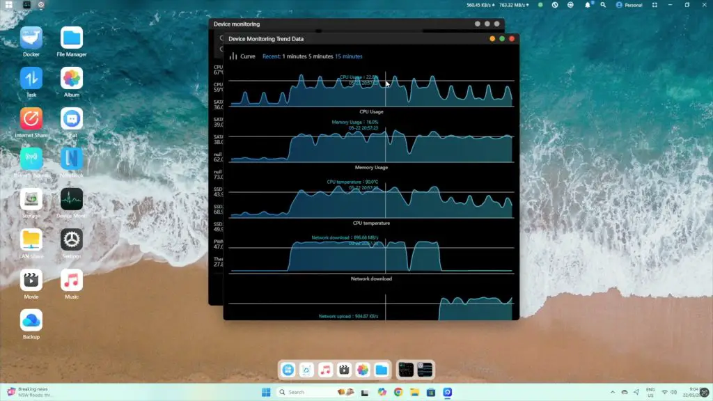
I decided to take a closer look at thermal performance since we were getting low reading and writing speed when using the RAID 6 main storage volume. These workloads caused high CPU temps (~90°C package, cores >70°C), which suggested we may be running into thermal throttling. The CPU usage hovered around 25–30%, meaning performance is limited by cooling rather than raw processing power.
Switching fan modes to Turbo didn’t help much, the thermal limitations remained. This indicates that the heatsink is just not capable of getting the heat away from the CPU.
The good news is that Orico has since upgraded the cooling system, replacing the aluminum heatsink with a larger copper one and improved ducting. This should significantly reduce thermal issues.
Noise & Power Consumption
Noise levels (measured at 15cm):
Silent mode: ~39dB (very quiet)
Auto/Standard: ~47dB
Turbo: ~55dB
Even in Turbo, the fans aren’t overly loud. The sound of the 10 mechanical drives is more noticeable than the fans.
Power draw:
Idle (drives on): ~70W
Full load: ~120W
Idle (no drives): ~25W
These figures are very reasonable for a system of this scale. It’s great to see that the power draw is realtively low since this is expected to run 24/7, so overall power consumption can become significant over time.
Privacy and Software Flexibility
I know some of you are probably wondering about privacy and people often have valid privacy concerns when using products with preloaded OS’s by the same company, but there is some good news here, this NAS fully supports local-only use, it doesn’t require an internet connection, cloud linkage or an online account to set it up. You can even turn off it’s internet connection or isolate it on your network if needed. There is no mandatory cloud syncing or forced telemetry.
No internet or cloud connection required
Fully local setup possible
No mandatory telemetry or account login
That said, the software still needs some refinement. At the time of writing this review, there is:
No web dashboard
Limited documentation and no official community support
Missing enterprise features like iSCSI
However, Orico is making steady progress. Since May, there have already been three version updates, which have added:
Bug fixes and translation improvements
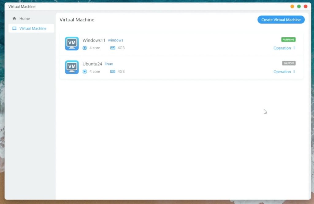
Virtual machine support
One-click Docker Compose
Preconfigured AI models (e.g., DeepSeek)
Also, the NAS is not OS-locked—you can install alternatives like Unraid or TrueNAS. I found Unraid works better out of the box, as it includes drivers for the 10G NICs.
Final Thoughts On The ORICO CF1000
If you only need basic backups or streaming 1080p content, the CF1000 may be overkill, but this is just one product in their new CybderData range, so you should consider one of Orico’s lower-end models.
The CF1000 is well suited and worth taking a look at if you:
Work with 4K video
Run multiple services or containers
Need lots of fast, redundant storage
It’s also well-designed, powerful, and looks fantastic too.
Currently, the CF1000 is only available through Kickstarter, with the campaign running until August 7th. Here’s a link to it if you would like to get your own CyberData NAS.
One Final Note on Crowdfunding
As always with crowdfunded products, there’s a degree of risk. Orico is a well-established company, and I’ve tested a fully working pre-production unit. But the final product may still undergo changes. They’ve clearly invested a lot into development already, and it’s usable as-is, but it’s important to approach any crowdfunded product with realistic expectations.
Let me know in the comments section below what you think of the CF1000 or Orico’s broader CyberData NAS range.
Over the past few years, I’ve built several Raspberry Pi-based NAS (Network Attached Storage) devices. These range from a dual-drive setup using a Pi 4, a budget-friendly Pi Zero NAS for under $35, and more recently, an all-SSD NAS running on a Raspberry Pi 5. While each project had its advantages, today’s build takes things up a notch — we’re going for a more practical, fully-featured 4-bay NAS that resembles a traditional commercial unit.
Here’s my video of the build, read on for the write-up;
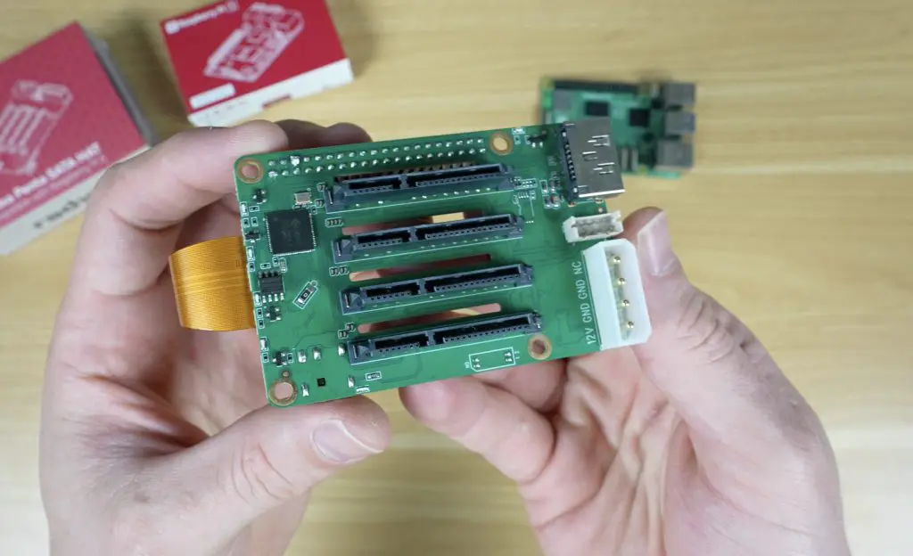
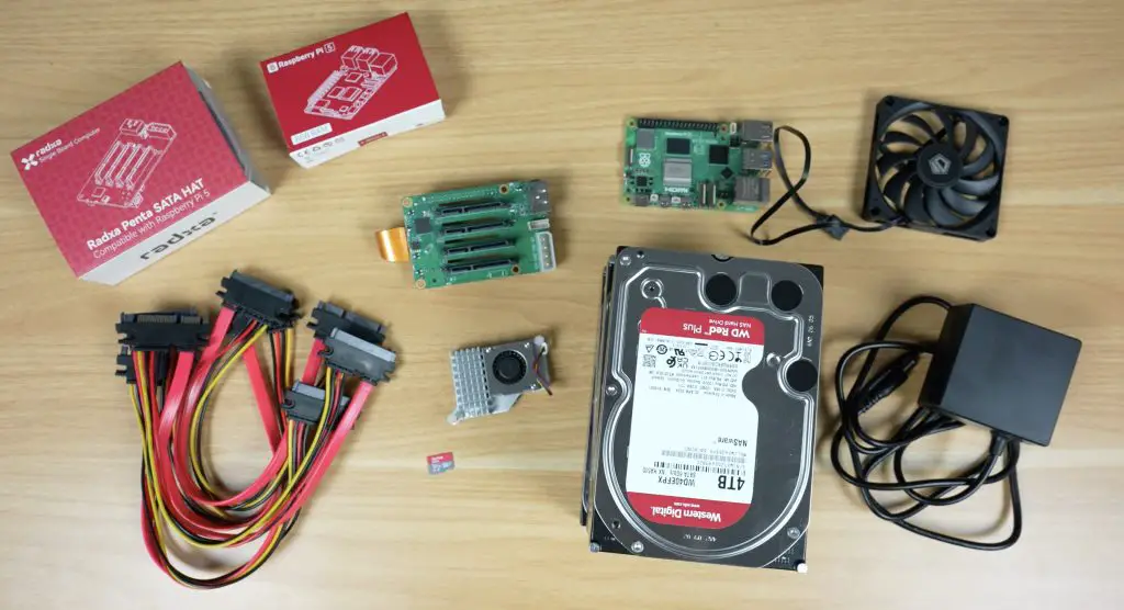
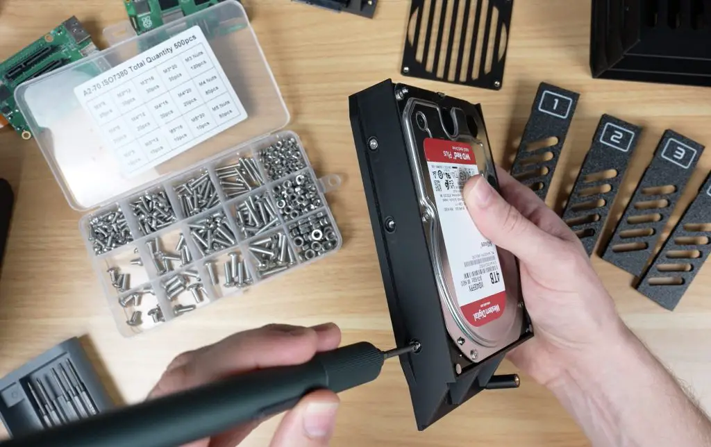
For this project, I’m again using the Raspberry Pi 5, making full use of its PCIe port by attaching the Radxa Penta SATA Hat, which provides four SATA ports. Technically, the hat includes a fifth port (hence the penta SATA name), but it uses a different connector and is inconveniently positioned, so I’m sticking with four.
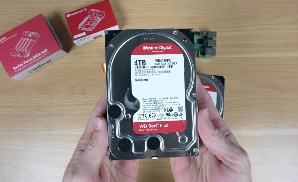
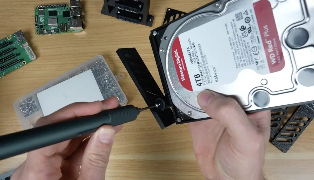
For storage, I’m using four 4TB WD Red NAS drives, providing a good balance of capacity and reliability.
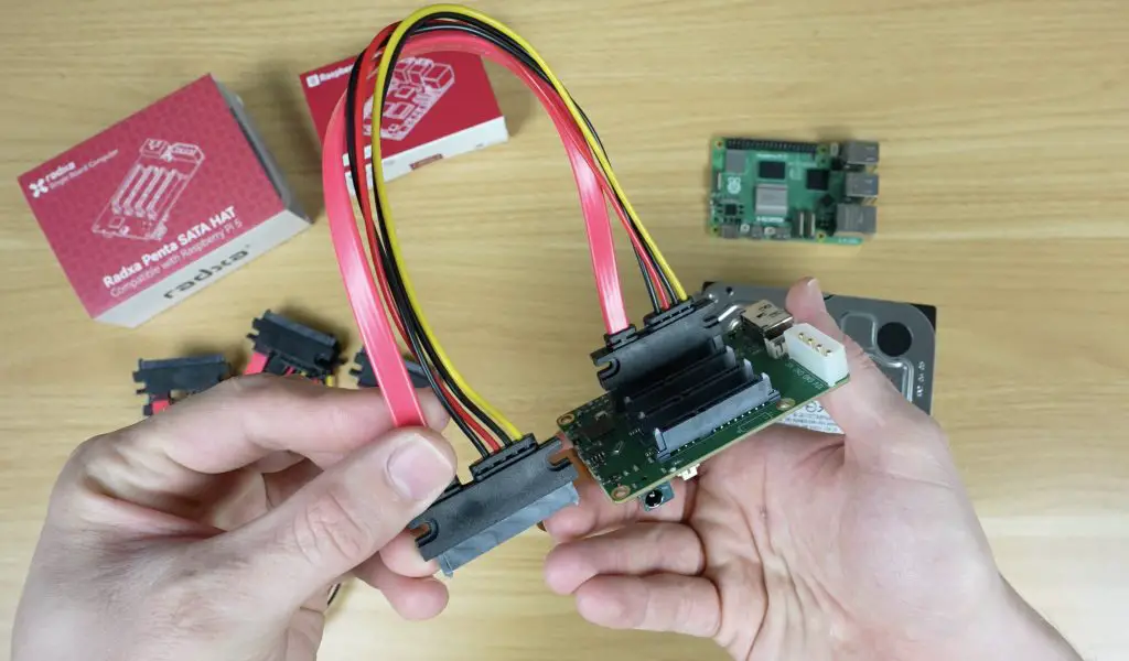
Because 3.5″ drives are too bulky to plug directly into the Radxa hat, I’m using SATA extension cables. The particular ones I’ve chosen have mounting holes, allowing me to design a custom bracket to align them properly with the drive trays.
To complete the setup, I’m using:
A Pi 5 active cooler for CPU thermal management
A microSD card to run the operating system
A 12V 40W power adapter to power the NAS
A slim 12V 80mm fan to cool the drives and internal components
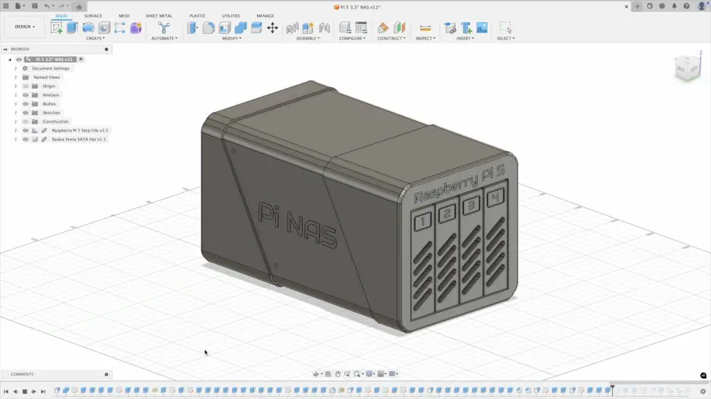
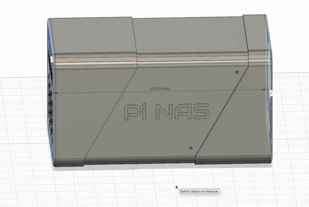
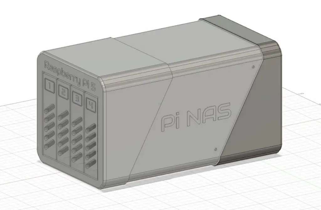
Designing the NAS Enclosure
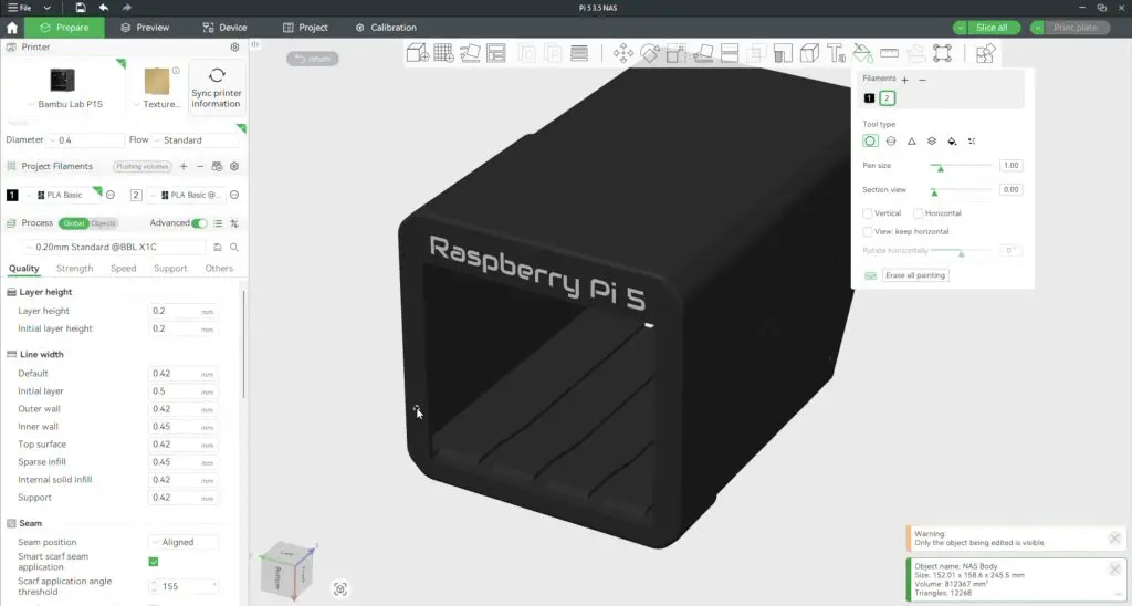
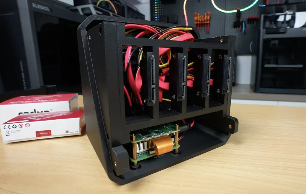
I designed the custom 3.5″ Pi NAS enclosure in Fusion 360.
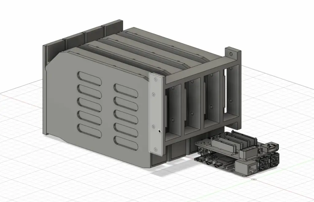
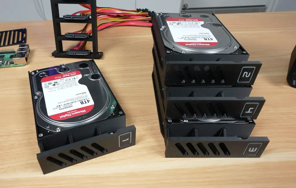
The design features:
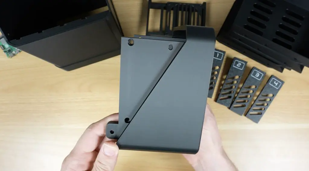
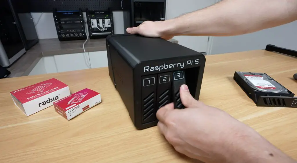
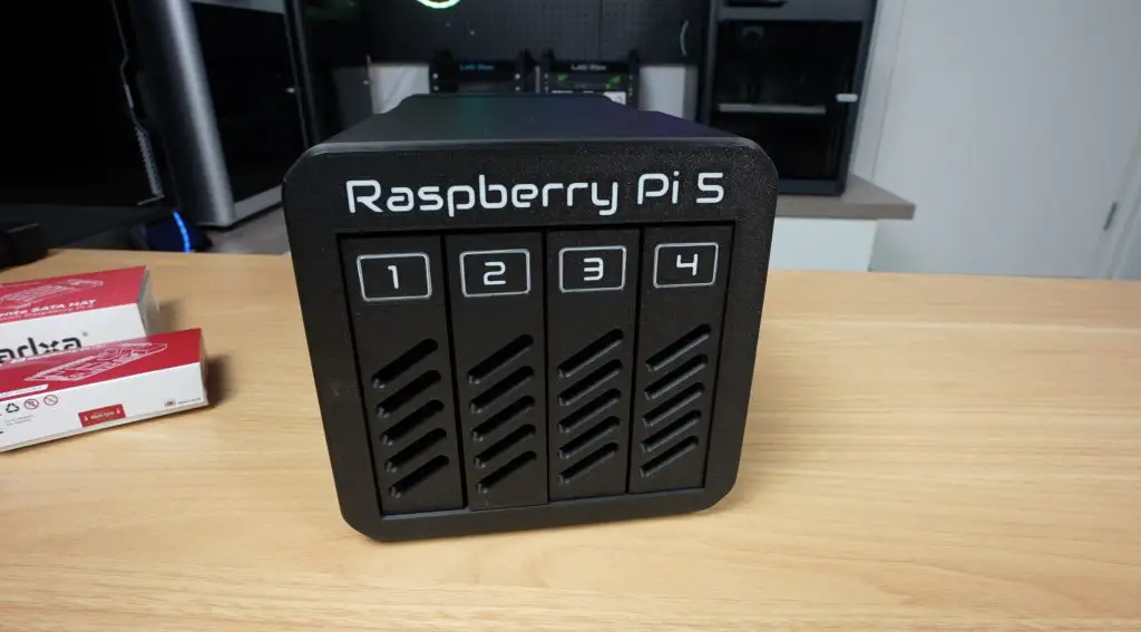
Individual drive trays with pull-out levers for easy access
A mounting bracket for the SATA extension connectors so that drives can slide in and plug directly.
The Pi and Radxa stack behind the drives, as we don’t need HDMI or USB-C access
A barrel jack extension for clean power supply routing to the Radxa hat
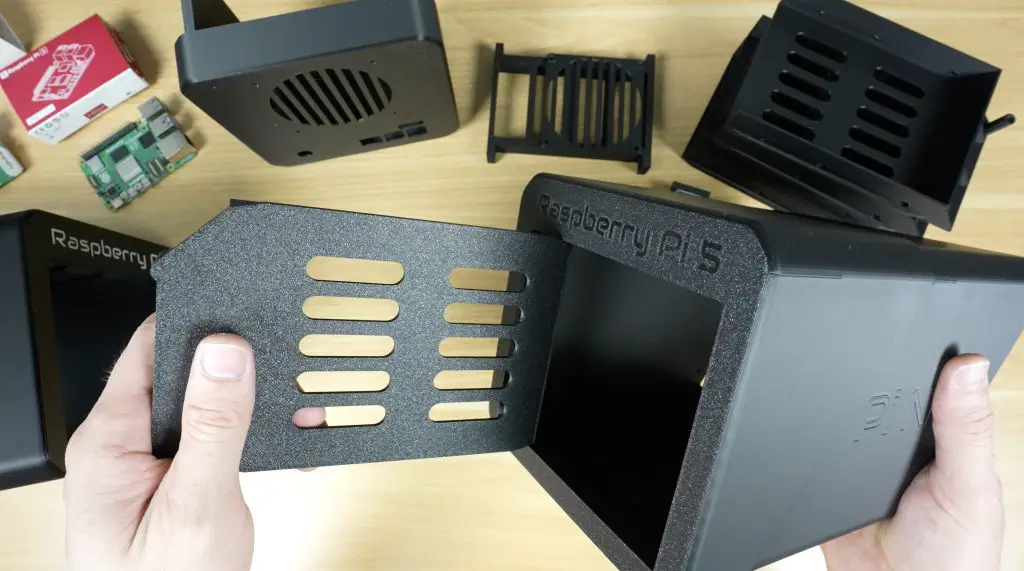
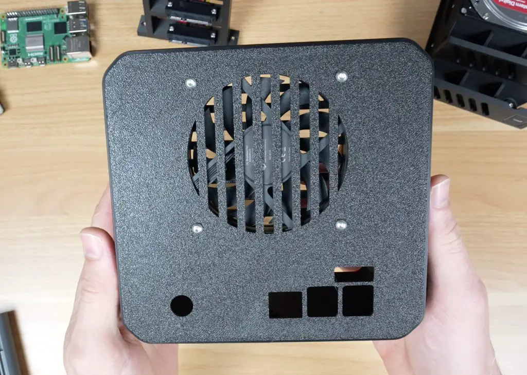
An 80mm fan mount above the Pi to draw air through front vents and exhaust it at the back
A vented fan guard to prevent cables from catching in the fan blades
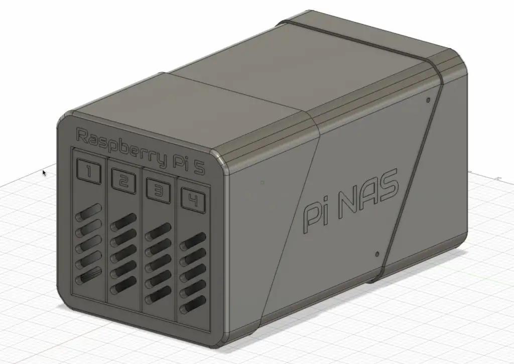
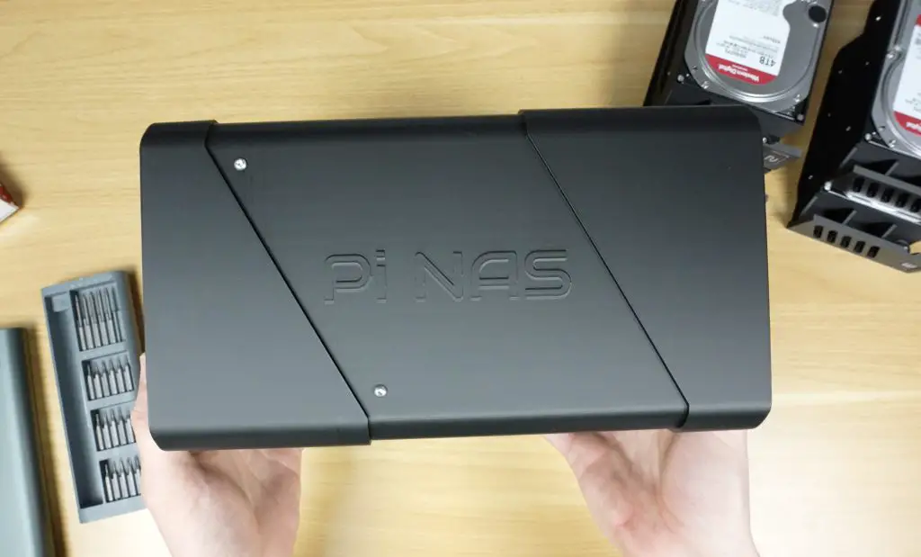
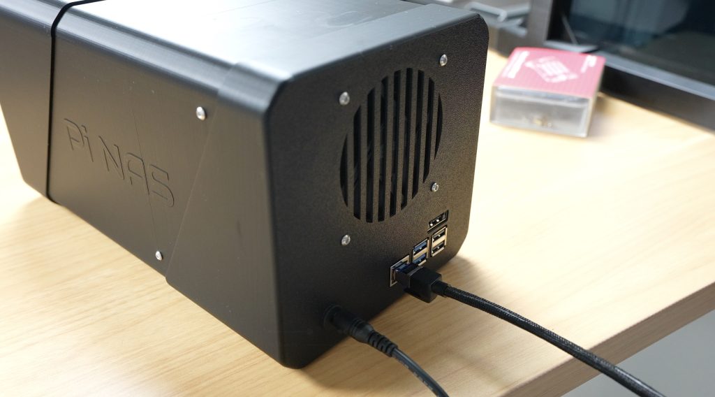
All of the components are enclosed in a housing that closely resembles a traditional 4-bay NAS.
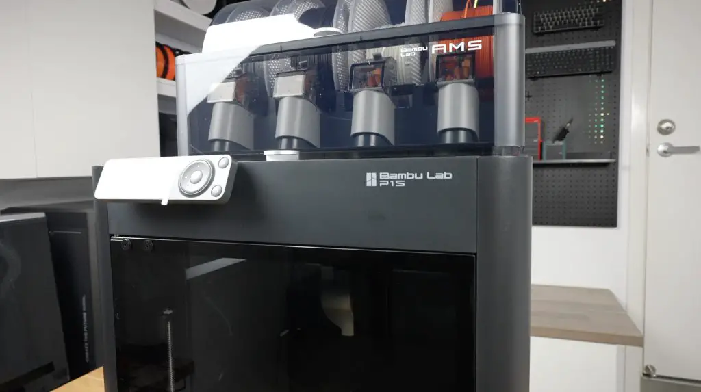
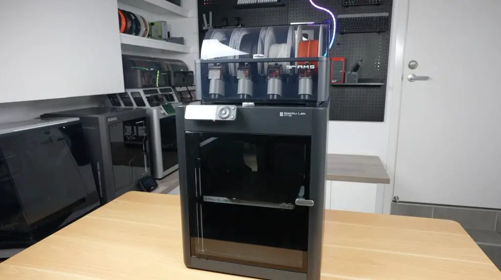
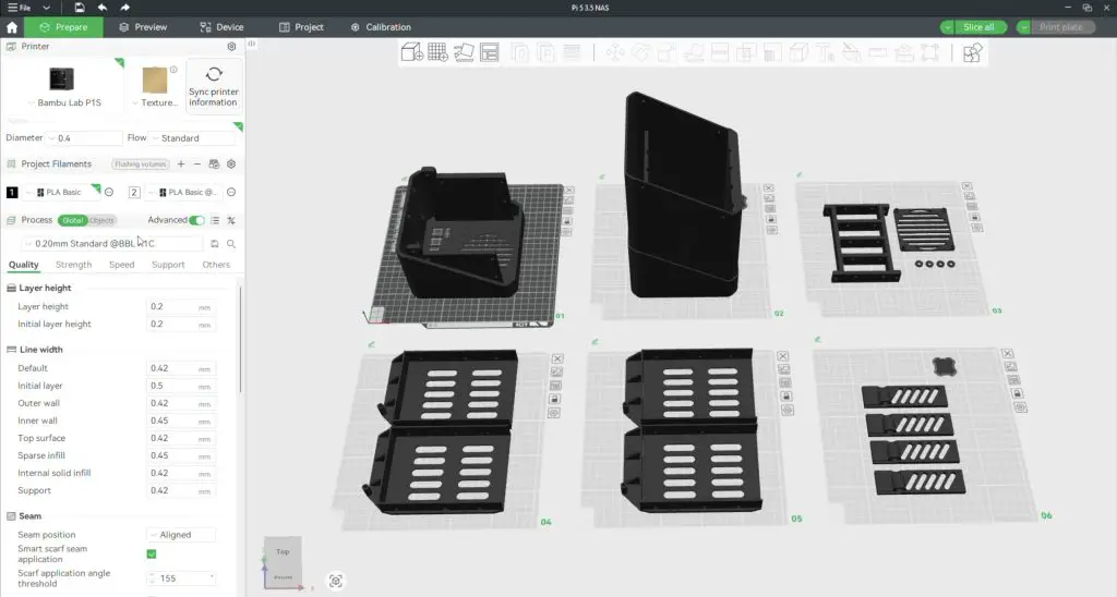
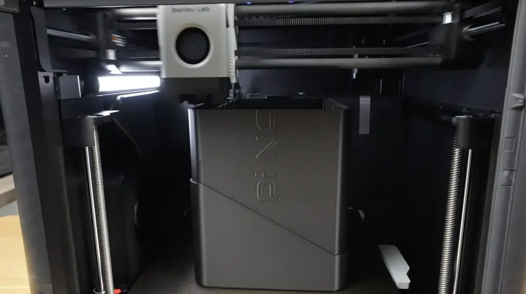
To bring the 3D model to life, I used the Bambu Lab P1S Combo, one of Bambulab’s mid-range CoreXY printer with:
High-speed enclosed printing
Multi-material support through the AMS (Automatic Material System)
Reliable out-of-the-box performance which is perfect for a functional project like this
Handling the Large Print Size
One challenge with the design is its length. The full enclosure is 275.5mm long, while the P1S has a 256mm max build volume along each axis. To work around this, I split the enclosure along a diagonal. This hides the seam as part of a design accent and, as a bonus, eliminates the need for print supports.
The enclosure was then exported and sliced across six build plates using Bambu Studio, and printed in:
Black PLA Basic for the enclosure
White PLA Basic for the front panel and tray lever text
I also used all default settings/presets for the textured PEI build plate, 0.2mm standard print profile and PLA Basic.
The entire enclosure uses nearly 1kg of filament and is going to take just under 24 hours to print. Because the text is only a couple of layers deep, we only have 5g of filament waste for the two-color prints on the front panel.
Print Results & Design Adjustments
The Bambu P1S produced high-quality parts straight off the printer. There was no warping or stringing, and the parts had accurate tolerances. This was especially impressive since it was the printer’s first large print out of the box with just basic setup and auto-calibration.
I did need to reprint the enclosure halves to add clearance for the drive tray guides and mounting holes for the Pi which I forgot about. Both small fixes, but worth mentioning.
Assembling the 3.5″ Pi NAS Enclosure
Adding The Brass Inserts
The 3D printed components are held together with M3 screws into brass inserts, so we need to get those installed using a soldering iron;
Four go into the back half of the enclosure for joining the two parts together
Four go into the SATA cable holder to mount it to the case
Eight more go into the cable holder to secure the SATA connectors to the holder
One for each drive tray to mount the tray lever with a 3D printed washer
Installing the SATA Cable Connectors On The Bracket
Each SATA connector is fastened with two M3x8mm button head screws. I added two brass inserts and installed the one on the end first, I then used a long hex key to secure them through the holes made for the subsequent inserts. This makes it easier to get to each set of screws, since its quite compact. This process was repeated for all four connectors.
Assembling the 3.5″ Drive Trays
Each 3.5″ HDD is mounted using four countersunk drive screws. The tray lever is then attached with an M3x8mm screw and a 3D printed washer, allowing it to pivot between the pulled out and stowed positions. This process is repeated for all four trays.
Installing the Fan & Power Jack
The 80x10mm 12V slim fan is mounted to the rear of the case using four M3x16mm screws. Make sure that it is aligned to push air out of the enclosure. I oriented the vent guard slots horizontally to minimize cable interference.
I also installed the barrel jack extension for the Radxa hat’s power input.
Pi Stack Assembly
Next we can assemble the Pi stack to install it into the enclosure. OMV (Open Media Vault) is the software package that we’re going to be running and that requires Raspberry Pi OS Lite to be flashed onto the microSD card – so get that done before installing it.
To assemble the Pi stack, we need to;
Plug the prepared microSD card into the Pi’s card reader.
Install the active cooler on the Pi. You’ll need to remove three heatsink fins to clear the Radxa hat’s barrel jack. This is a bit of a design flaw with the hat.
Install the included standoffs from the Radxa kit onto the Pi with the threads facing upwards
Connect the PCIe ribbon cable to the Pi.
Mount the Radxa hat onto the Pi’s GPIO header and secure it.
Plug in the Molex fan power cable before installing the stack, as there’s not enough clearance to plug it in once installed.
Secure the Pi stack in the case with four included M2.5 screws
Connect the fan and power cables
Next we need to install the SATA power cable assembly above the Pi. Start by plugging each of the connectors into the Radxa Penta SATA hat. Then align the bracket with the holes in the back enclosure half. Make sure the SATA cable holder is installed with the data connectors on the bottom — I initially installed it upside down by mistake. Secure it with another four M3x8mm button head screws.
Do one more check to make sure that there isn’t too much pressure on any of the SATA connectors going into the Radxa hat and also check that the fan is still able to rotate freely and doesn’t have any cables caught up in it.
Final 3.5″ Pi NAS Enclosure Assembly
Slide the two enclosure halves together and secure them with four M3x8mm button head screws. You can also use black screws for a cleaner finish if you’d prefer.
I finished it off with some small rubber feet on the bottom of the case for vibration isolation, and the NAS is readyto install the drives. These each slide into place until you feel them plug into the connectors at the back.
Booting Up the NAS & Installing OMV
To boot up the NAS, we first need to plug in an Ethernet cable and then the 12V power supply.
Give the Pi a few minutes to boot up and then, find its IP address through your router’s DHCP table or using a utility like Angry IP Scanner.
Use SSH to access the Pi and then update the Pi and install OpenMediaVault (OMV) with the following commands:
This script takes about 5 minutes and you’ll need to reboot your Pi when you’re done.
Important note: As of 17 May 2026, OMV’s update to kernel 6.12 seems to be incompatible with the Radxa hat, or at least some versions of it. If this is the case, you’ll need to fall back to an earlier version of OMV running kernel 6.6.
Enable The PCIe Port
Before drives will show up, we need to enable the PCIe port on the Pi. Add the following lines to the Pi’s /boot/firmware/config.txt:
dtparam=pciex1
dtparam=pciex1_gen=3
And again reboot the Pi.
Once the Pi has rebooted, the drives should show up and you can confirm this by entering:
lsblk
You should see something like (one for each drive):
sda
sdb
sdc
sdd
Configuring OMV
Once we’ve got OMV installed and the PCIe port enabled, we can acess the OMV web dashboard by entering the Pi’s IP address in our browser. The default login is:
Username: admin
Password: openmediavault
Be sure to change these credentials after logging in.
I’m not going to go into too much detail on setting up OMV since there are loads of guides available already. Essentially I’ve followed the following steps:
Set up the drives in a RAID 5 configuration, providing 12TB of usable space with redundancy.
OMV 7 on a Pi doesn’t allow you to create a RAID array, you’ll need to do this through the terminal.
Create a Storage Volume
Created a Shared Folder on the Storage Volume
Create a User Account with permissions to access the Shared Folder
Enable the SMB service
Testing The 3.5″ Pi NAS
Transfer Speeds
To test the Pi NAS’ transfer speeds, I’ve mapped the network drive to my Windows 11 PC. I then tried copying a large 30GB video file across to the NAS. I got an average write speed of about 110MB/s with some short dips along the way. This is around 900Mb/s, so we’re likely saturating the gigabith Ethernet port on the Pi.
I then tried copying the same file from the NAS back to the PC. This is a bit faster and more consistent, I got an average speed of 113MB/s.
I then tried an automated tested using a 1GB file size got similar results again. Writes were around 110MB/s and reads around 110MB/s.
Like with my SSD Pi NAS, because it looked like we were saturating the Ethernet port, I then tried using a 2.5G USB Ethernet adaptor plugged into one of the Pi’s USB 3 ports.
This improved writing to the NAS to an average of around 200MB/s, again with a few dips, and reading from the NAS I got a faster 250MB/s. So writing to the NAS is now likely being nottlenecked by the software RAID parity calculations being done on the Pi’s CPU.
This makes the 2.5G network adaptor an easy and worthwhile upgrade for less than $20. It makes a big difference to the NAS’ performance, especially when large amounts of data are being transferred.
Power Consumption
I used an AC power meter to measure the NAS’ power consumption under a full writing load and at idle.
Idle: ~18W
Under Load: ~30W
This is higher than my SSD Pi NAS (~9–12W), but is reasonable for a NAS have four large mechanical drives. For comparison, my Asustor NAS idles at around 18W with the drives spun down, so this NAS does great with them still running.
Thermals and Noise
Thermally, the ventilation ports on the front and the 80mm fan at the back do a great job at keeping the NAS cool, even under a full load.
The only real negative for this build is that it is quite noisy. With the 80mm fan running, we get a sound level of about 54dB at 20cm.
Final Thoughts on my 3.5″ Pi NAS Build
That wraps up the build of my 4-bay 3.5″ Raspberry Pi 5 NAS. It offers solid performance, a functional and aesthetic 3D printed design, and the flexibility to use OMV or another NAS OS for your home NAS needs.
I’ve uploaded the 3D print files to MakerWorld. If you’ve got a Bambu Lab A1, P1S, or X1C, you can use my preconfigured print profiles to start printing directly from the Bambu Handy app. If not, download the files and slice them in your own slicer.
If you’re considering getting a 3D printer, the Bambu Lab P1S is a fantastic option. It’s fast, supports multi-material printing, and its enclosed design handles a wide range of materials. It’s perfect for makers and you won’t outgrow its capabilities any time soon.
Let me know what you think of my Pi NAS build in the comments section below.
SunFounder have returned with the latest iteration of their Pironman case. This time, it’s called the Pironman 5 Max, built specifically for the Raspberry Pi 5. This case brings a host of upgrades, including dual NVMe support, a sleek black aluminium body, and tinted acrylic panels.
At $95 for the standard kit, it’s definitely on the higher end for Raspberry Pi enclosures, but it makes up for that with a range of inclusions and features. Most notably, the ability to run a Hailo-8L AI accelerator alongside an NVMe SSD. That makes it ideal for AI applications like onboard voice recognition, object detection, and real-time pose estimation.
Let’s walk through the case design, assembly, features, and performance testing to see how it holds up.
Here’s my video review of the case, read on for the write-up;
The Pironman 5 Max arrives in a clean, white branded box. Inside, you’ll find the aluminium shell, fans, cooler, expansion boards, and mounting hardware, everything you need to get up and running.
This is the third-generation Pironman case, and visually, it carries forward the design of its predecessor while swapping the silver and clear acrylic for a more refined black aluminium and tinted acrylic look. You’ll also notice upgraded features like dual M.2 NVMe ports, programmable RGB lighting, and a tap-to-wake OLED stats display.
Assembling The Pironman 5 Max Case
Like its predecessor, the Pironman 5 Max case is quite complex and requires some effort to assemble. It’s not difficult, thanks to the well-illustrated instruction sheet and clearly labelled screws, but it’s more involved than your average snap-together Pi case.
Here’s a quick overview and some photos of the assembly process;
Install Standoffs – Attach various lengths to one half of the enclosure.
Prepare the Pi – Plug in the carrier boards and mount the Pi 5 into the case.
Install the Cooler – Apply thermal pads to the CPU, WiFi module, and power circuitry. The included Ice Cube cooler uses the same mounting holes as the Pi 5 Active Cooler and similar “press into place” spring mounts.
Add the NVMe Adapter – The adaptor supports 2230 to 2280 drives. I installed the Hailo-8L AI accelerator in the top port and a Lexar 2280 NVMe SSD in the bottom (there is functionally no difference between ports)
Attach the Fans – These mount on the back panel.
Optional Camera Support – If you’re using a camera module, this is the time to install it (I decided to do this later as I wanted to test the case without it first).
Add the OLED & GPIO Expansion Board – This board includes the GPIO extension and RGB lighting. The display gets stuck onto the front panel.
Assemble the Shell – Screw the aluminium halves together.
Finish with Acrylic Panels – The dark tinted panels give it a clean, high-tech look. The power button gets added to the front panel before installing it.
Install the Rubber Feet to finish it off.
The total assembly time was around 25 minutes, and everything went together quite smoothly. There are also spare screws and cables included, which is a helpful touch.
First Boot & Software Setup
With Raspberry Pi OS pre-installed on the NVMe SSD, we can more stright on to booting it up. The OLED display and RGB lighting won’t function right away, they requiresome additional setup and software.
Fortunately, setup is easy. A quick config change and GitHub install later, and everything was up and running. I followed the instructions from SunFounder’s wiki and had no issues. They’ve also confirmed compatibility with other operating systems like Home Assistant, Ubuntu, and Kali Linux.
After rebooting, the OLED display shows:
CPU temperature and usage
RAM and storage capacity
IP address
The display goes to sleep after 10 seconds by default, but you can wake it with a tap or adjust the timeout in the config files.
The Pironman 5 Max Web Dashboard
One of my favourite features from the previous Pironman case was the web-based dashboard and I’m happy to repor that they’ve retained it. You can access it via your Pi’s IP address and port 34001.
From here, you can:
View system stats and logs
Graph CPU usage and temps (as well as a wide range of other metrics)
Customise the RGB lighting, including style, colour and animation speed
Control fan behaviour with presets like Quiet, Balanced, and Performance
The new PWM fans are a big step up. They can now be set to come on at different temperatures, unlike the previous version’s which were either always on or off.
Cooling Performance
To test the coolingperformance of the case, I set the fans to Always On and ran a 30-minute CPU stress test using CPU Burn.
Idle temperature: 35°C
After 30 minutes under full load: 46°C
Temperature delta: 11°C
So thermal performance is pretty good, leaving a lot of headroom for overclocking.
In comparison, these are the temperatures records on the same setup (without the Hailo AI module) on the previous generation case;
Idle temperature: 36°C
After 30 minutes under full load: 53°C
Temperature delta: 17°C
These results aren’t bad but you’d expect better from a case with three 40mm fans cooling a single Pi 5. I previously attributed this to restricted airflow from overly fine dust filters and inadequate inlets.
The Pironman 5 Max fixes this with front air inlets cut into the “Pironman” logo and filter-free exhaust fans, significantly improving airflow.
Fan Noise on the Pironman 5 Max
During the thermal stress test, I also measured the sound levels produced by the fans:
Quiet mode with fans turned off (idle): 29–33dB – practically silent
Always On (full load): 47dB – noticeably louder, potentially distracting if it’s close to you
So the added PWM fan control makes a huge difference for balancing performance and noise.
NVMe & Performance
I then wanted to test the performance of the dual NVMe adaptor. I did this by running James Chambers’ Pi Benchmark script three times on the Lexar NVMe SSD. These were the results:
Scores: 36,973, 36,947, 38,078
Average: 37,333
This aligns with expectations for a PCIe Gen 2 single-lane interface. You can boost it by switching to Gen 3 in the Pi’s config file.
Hailo AI Accelerator
Next, I tested the Hailo AI accelerator with an added Raspberry Pi camera and Hailo’s pretrained models from their Developer Zone. The performance was quite impressive:
Pose Estimation: 30fps, with CPU usage under 15%
Object Detection: Also ran at 30fps with low CPU usage
Person & Face Tracking: Handled multiple subjects in frame with ease
So using the Hailo AI module with a Raspberry Pi 5 significantly boosts performance for object recognition and pose estimation, enabling real-time inference with low CPU load and efficient power usage. It allows for smooth, high-speed AI processing directly on the device, ideal for edge applications without needing cloud resources.
Final Thoughts on the Pironman 5 Case
The Pironman 5 Max is a thoughtfully designed case with a premium look and a ton of functionality:
Dual NVMe slots for expanded storage or device support
Rear-only cable management for a cleaner setup
Full-size HDMI ports, avoiding the inconvenience of micro HDMI
Vast improvements to cooling and airflow
Great AI accelerator support
OLED display and RGB lighting with web-based customisation and controls
The case has the same footprint as its predecessor, 112mm x 117mm x 79mm, but packs in even more functionality.
The only real area for improvement would be more refined PWM control, allowing the fans to ramp smoothly with temperature rather than switching at fixed thresholds.
Despite the $95 price tag, the Pironman 5 Max offers great value considering it includes the enclosure, active cooling, dual NVMe support, OLED screen, RGB fans, and the necessary expansion boards. It’s one of the most complete cases currently available for the Raspberry Pi 5.
What do you think of the Pironman 5 Max? Let me know in the comments section below.