
The GMKtec NucBox K10 is a mini PC that packs a serious punch. Featuring a 14-core Intel Core i9 processor, impressive connectivity options, and upgradeable RAM and storage, it’s a compelling option for those looking to add a capable system to their homelab, or even as a quietand powerful workstation.
Here’s my video review of the NucBox K10, read on for the written review;
Where To Buy The GMKtec NucBox K10
Tools & Equipment Used For Testing
- Video Capture Card AVerMedia GC513 – Buy Here
- Infiray P2 Pro Thermal Camera – Buy Here
- Sound Level Meter – Buy Here
- Power Meter – Buy Here
Some of the above parts are affiliate links. By purchasing products through the above links, you’ll be supporting my projects, at no additional cost to you.
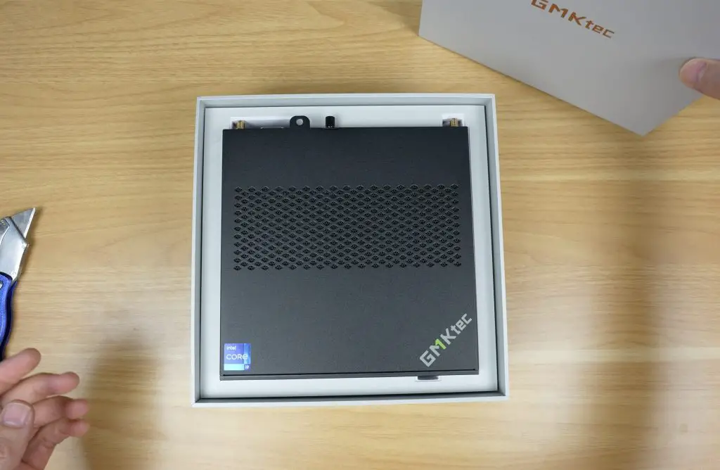
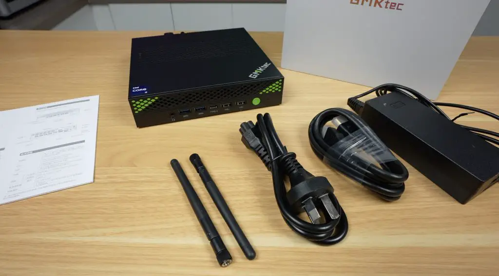
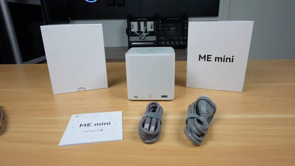
What’s in the Box?
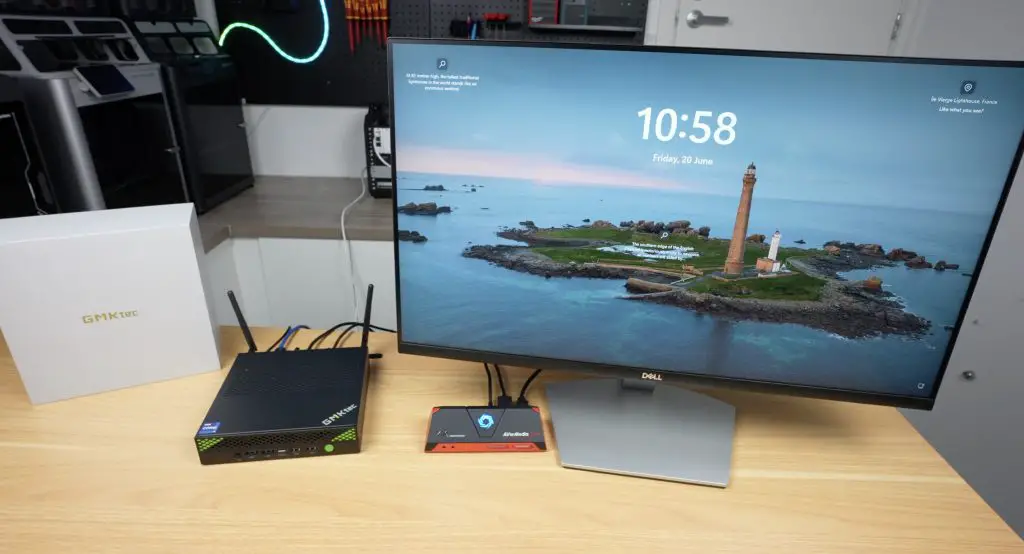
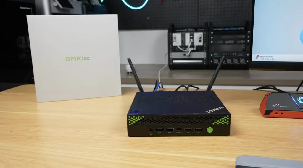
In the box, first up we’ve got the NucBox K10 and underneath it is a sleeve with a user manual. Two accessory boxes are included, one with an HDMI cable and a power cable, and another with a 120W power brick and two WiFi antennas.
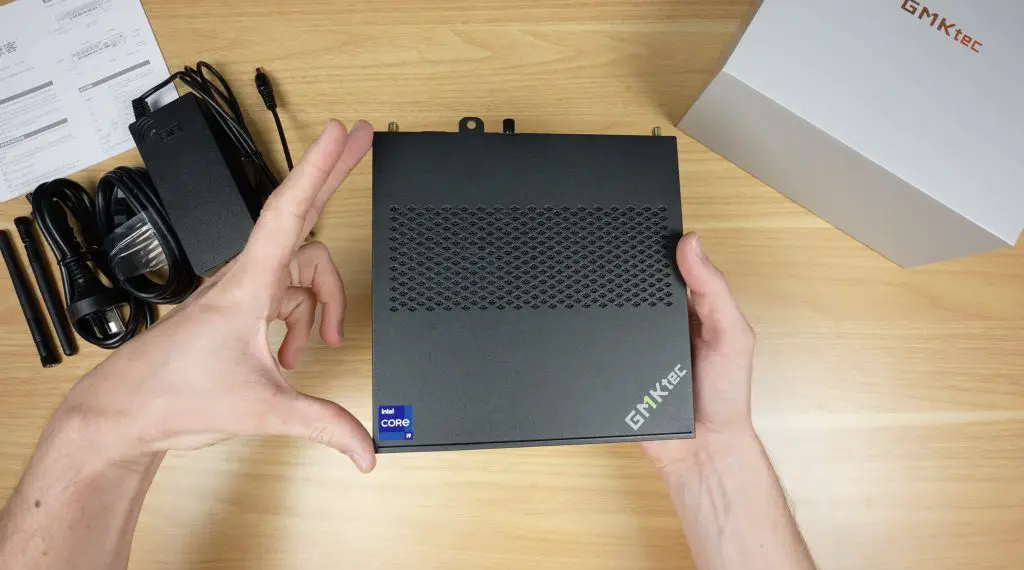
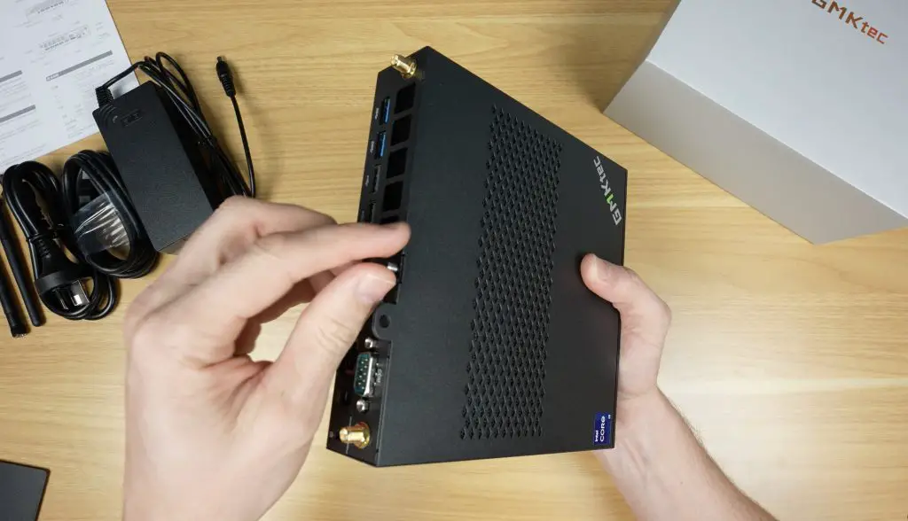
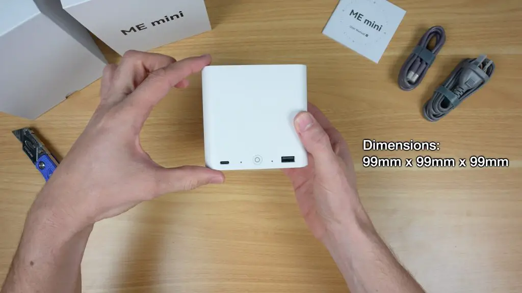
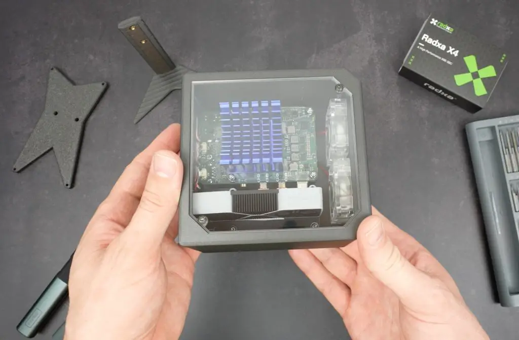
Design and Dimensions
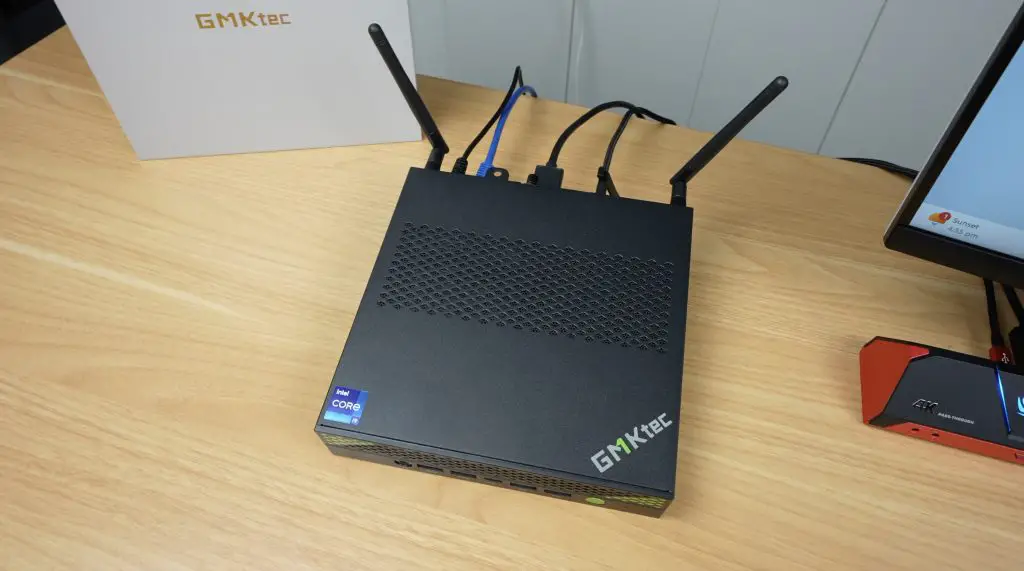
Physically, the NucBox K10 is on the larger side for a mini PC. It measures 178mm x 176mm x 40mm and weighs just over 1kg. The build feels solid, and it has a functional design that accommodates powerful hardware while maintaining a relatively small footprint.
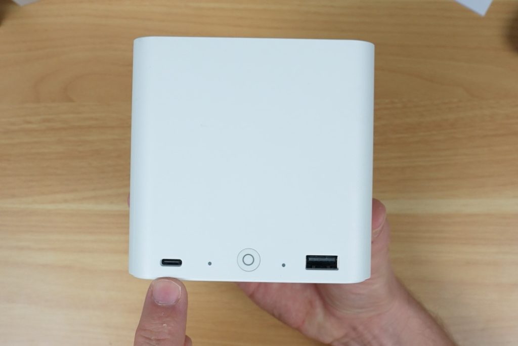
Ports and Connectivity Features
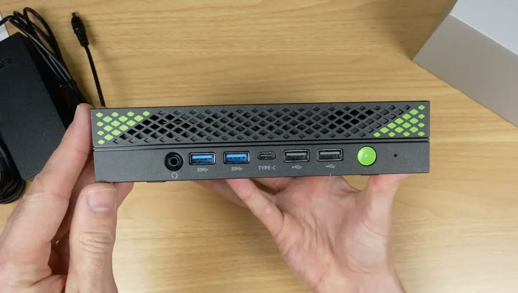
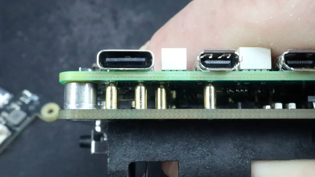
The NucBox K10 is well-equipped when it comes to connectivity. On the front panel, you’ll find:
- 1x 3.5mm audio jack
- 2x USB 3.2 Type-A ports
- 1x USB Type-C port with DisplayPort support
- 2x USB 2.0 ports
- Power button and power indicator LED
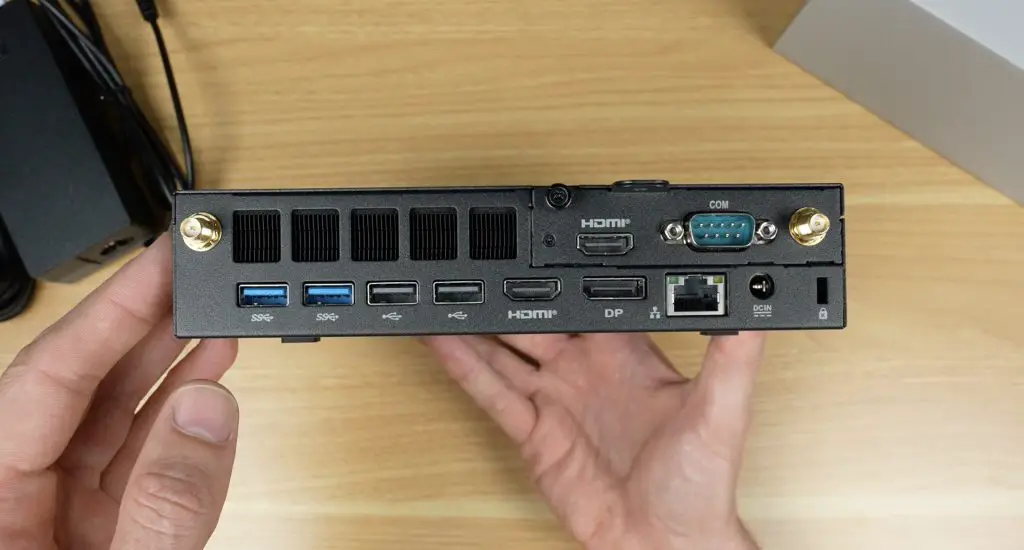
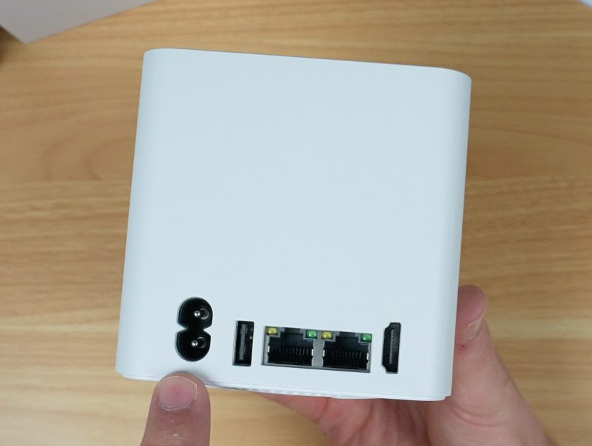
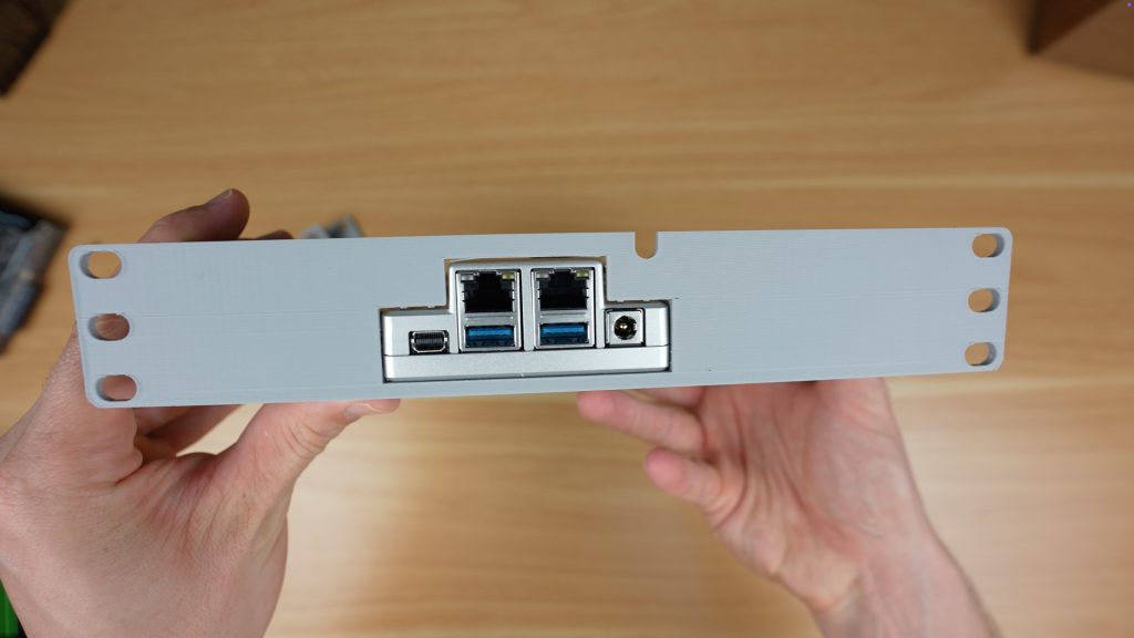
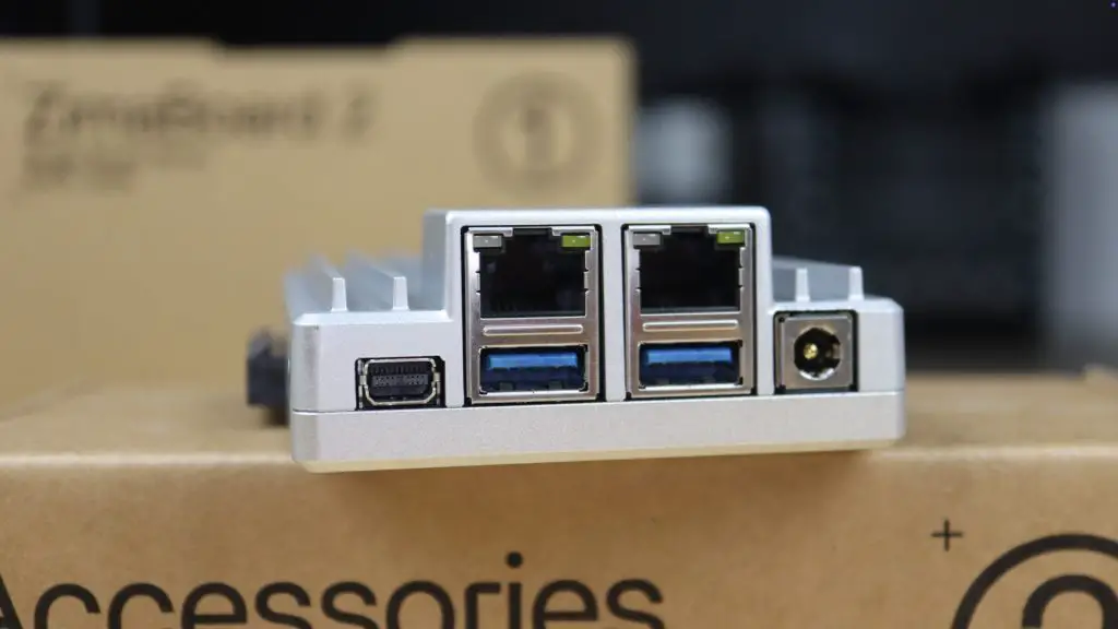
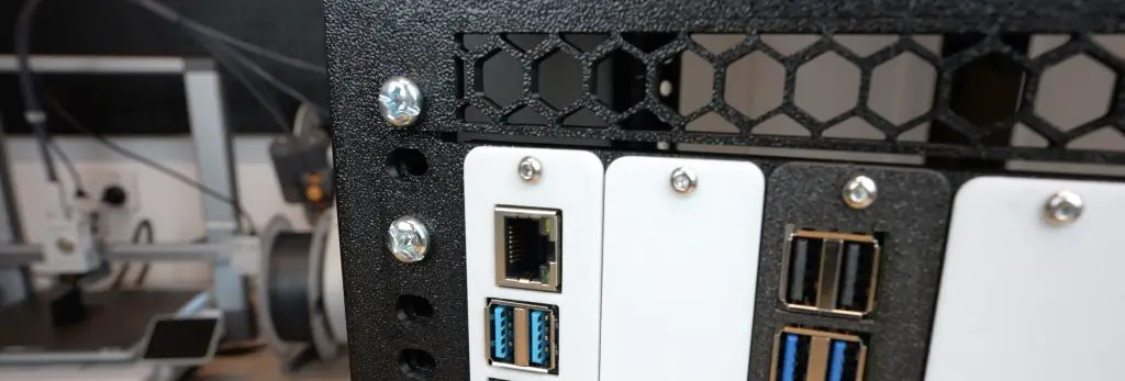
On the rear panel, the system offers even more:
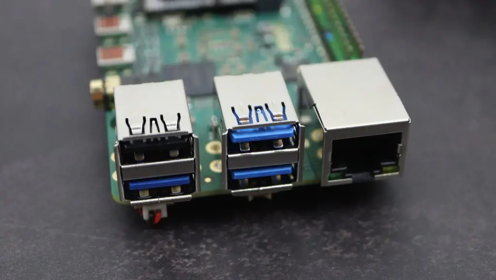
- 2x USB 3.2 Type-A ports
- 2x USB 2.0 Type-A ports
- 2x HDMI 2.0 ports
- 1x DisplayPort 1.4 (full-size)
- 1x 2.5G Ethernet port
- 1x RS-232 serial port
- 1x DC power input
- 2x WiFi antenna connectors
While the range of ports is quite good, it would have been great to see an additional USB Type-C port, or even USB 4 support, to make it more future-proof.
For wireless connectivity, the system includes WiFi 6 and Bluetooth 5.2, ensuring strong performance with modern devices and networks.
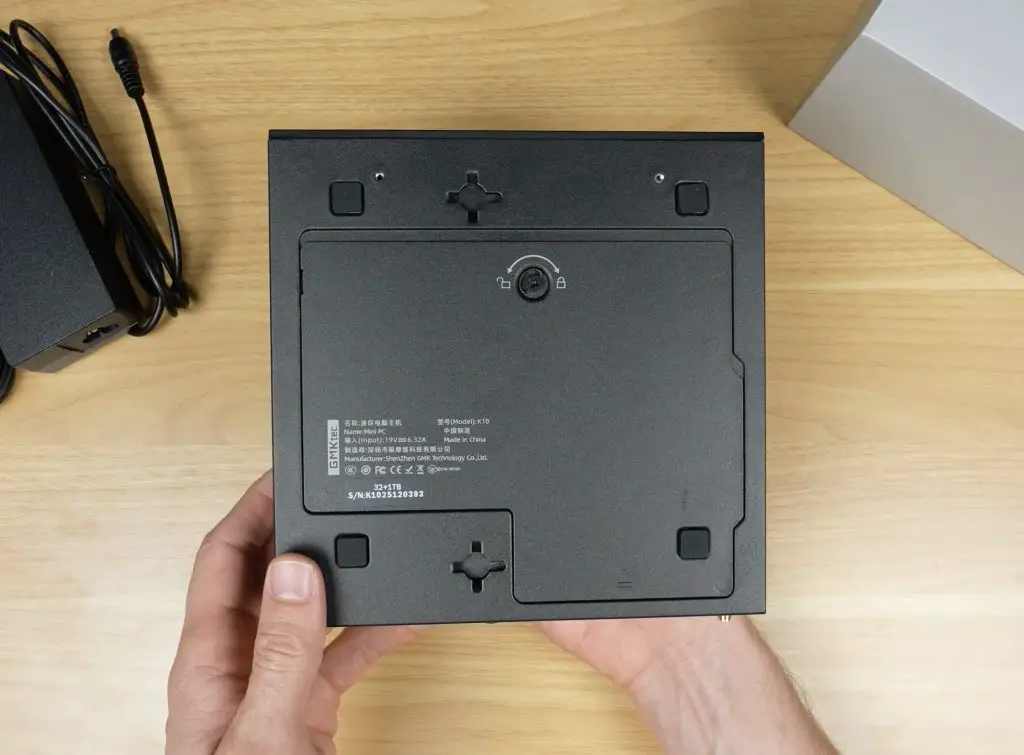
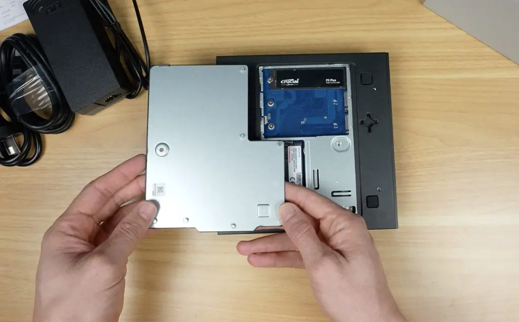
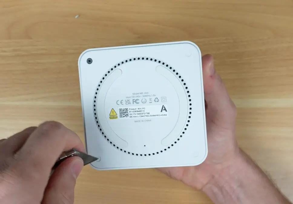
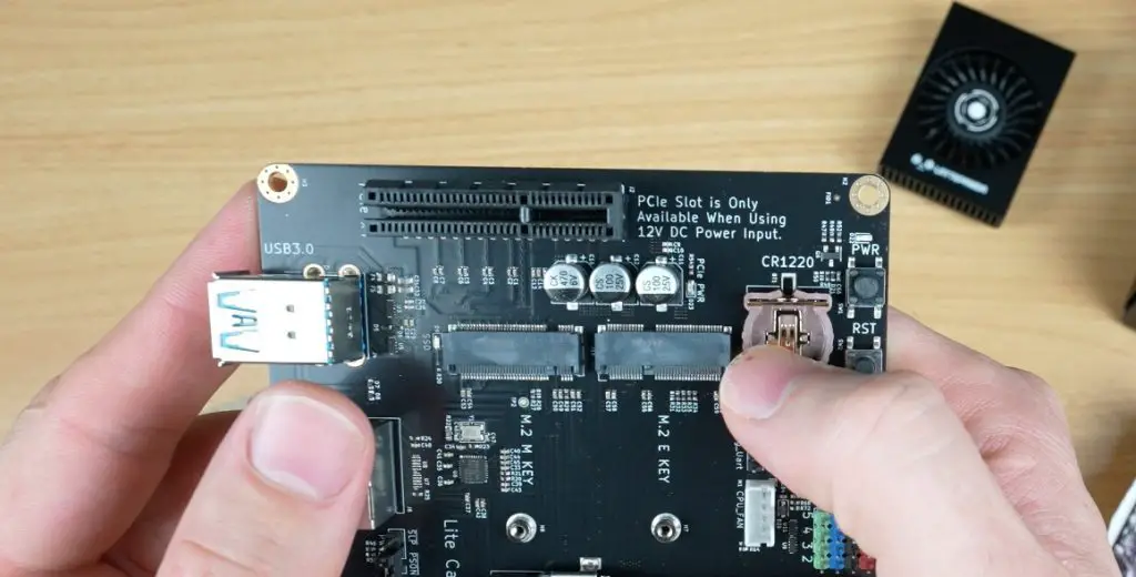
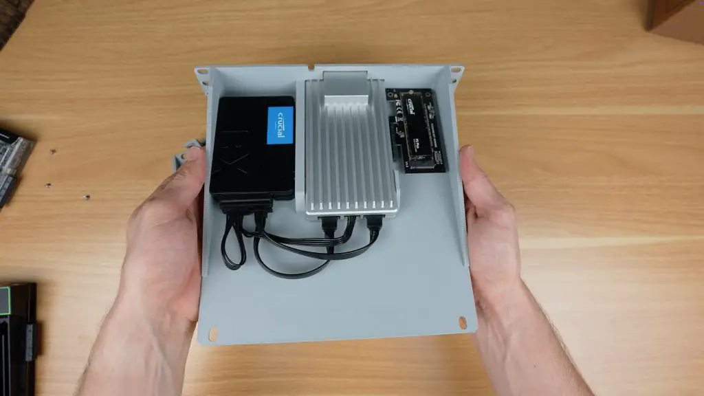
Ease of Access & Upgradeability
One of the standout features of the NucBox K10 is its tool-less access panel on the bottom. This provides direct access to:
- 2x SODIMM RAM slots
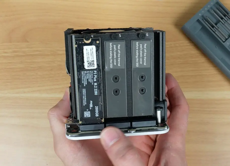
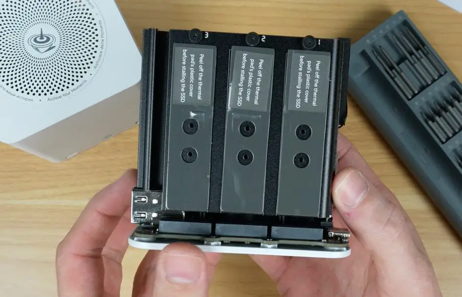
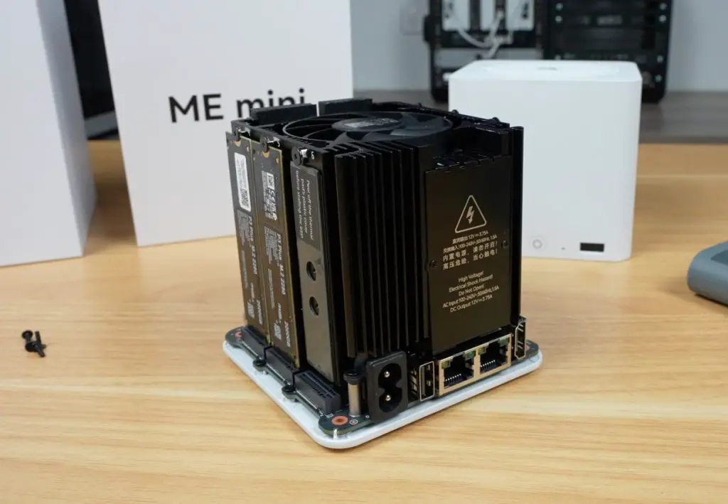
- 3x M.2 2280 NVMe SSD slots
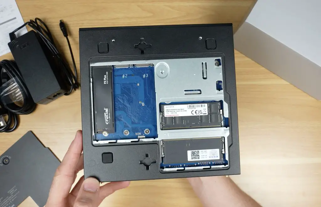
This design makes it incredibly easy to upgrade the RAM and storage without needing tools. The unit comes with 32GB of DDR5 RAM (two 16GB sticks in dual-channel configuration) running at 5200MHz. This is the CPU’s maximum supported speed, even though the supplied ADATA modules are rated for 5600MHz.

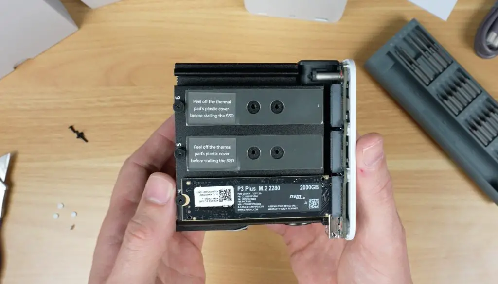
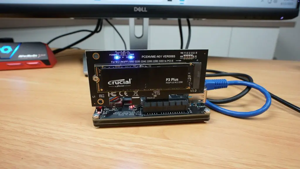
For storage, one of the three M.2 slots is populated with a 1TB Crucial P3 Plus NVMe SSD. It’s not common to see three M.2 slots in a mini PC. Two of these ports support PCIe Gen 4 x4 and one supports PCIe Gen 3 x3. The SSD also lacks a thermal pad, which could have helped with heat dissipation given its proximity to the metal access door.
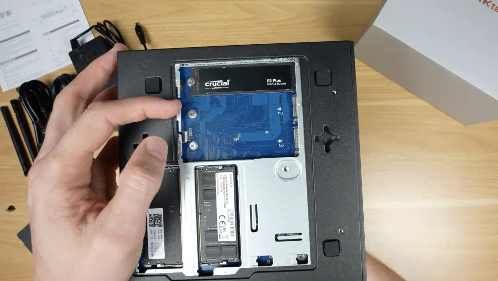
In additional to being upgradeable, its also good to see they’re using decent quality components and not a generic unbranded drive and RAM.
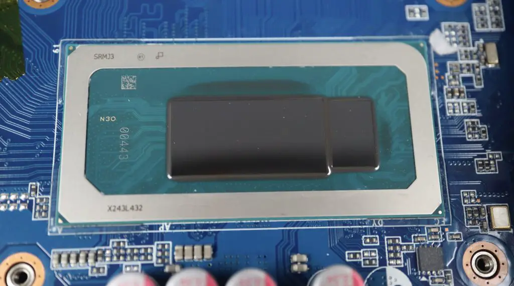
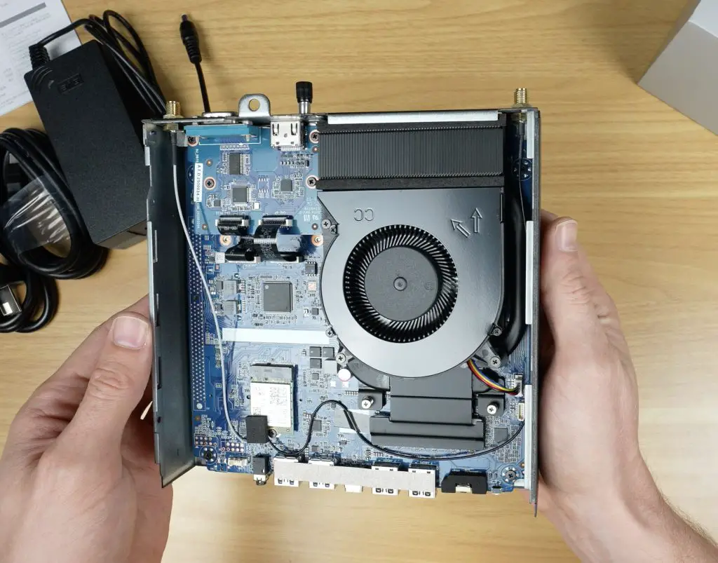
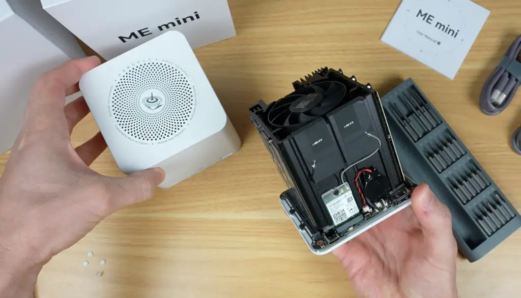
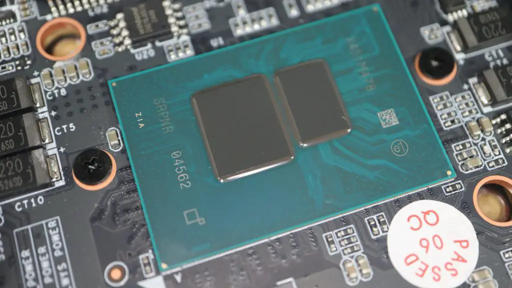
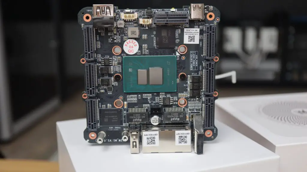
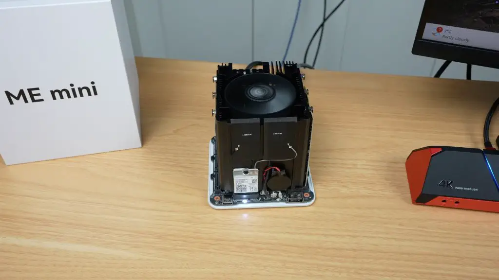
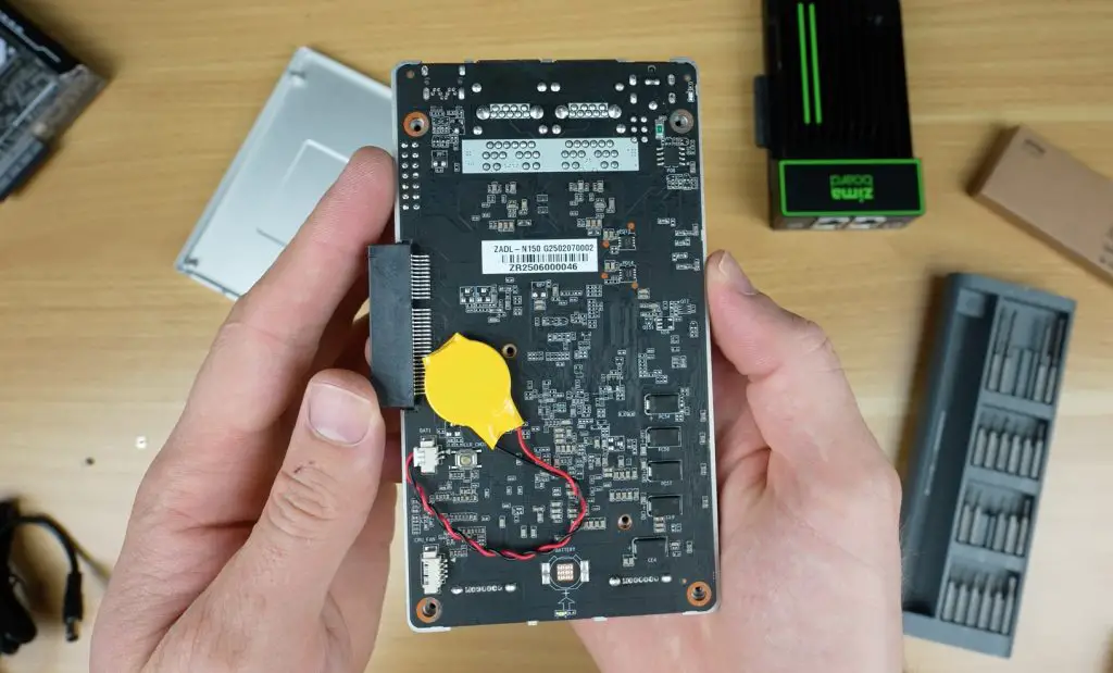
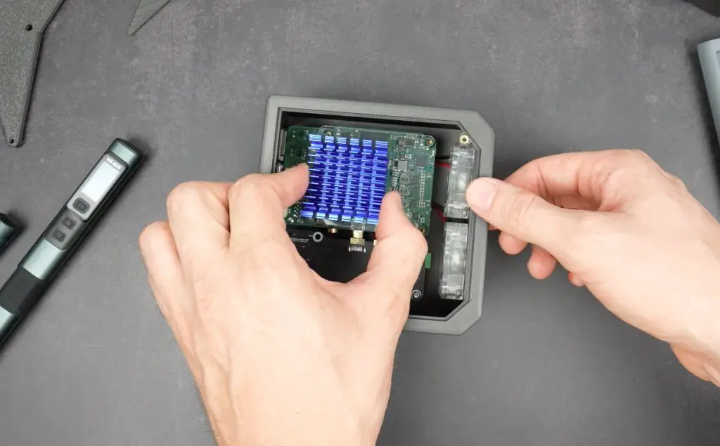
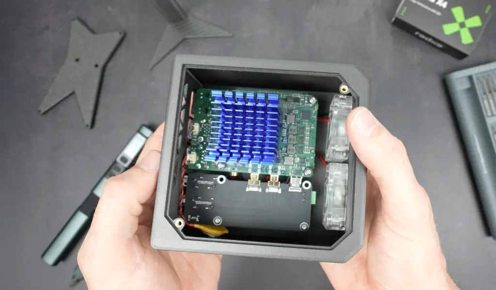
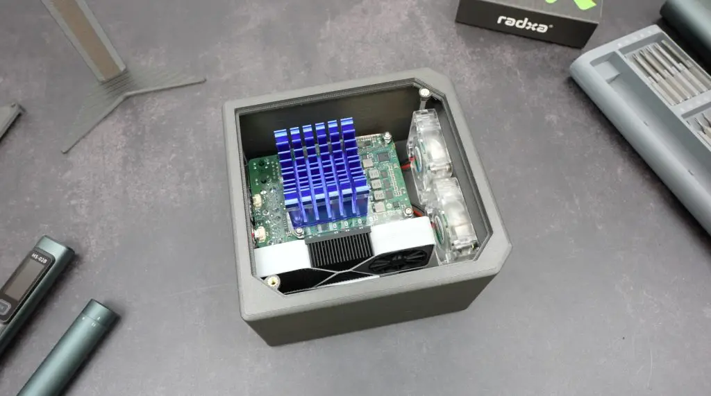
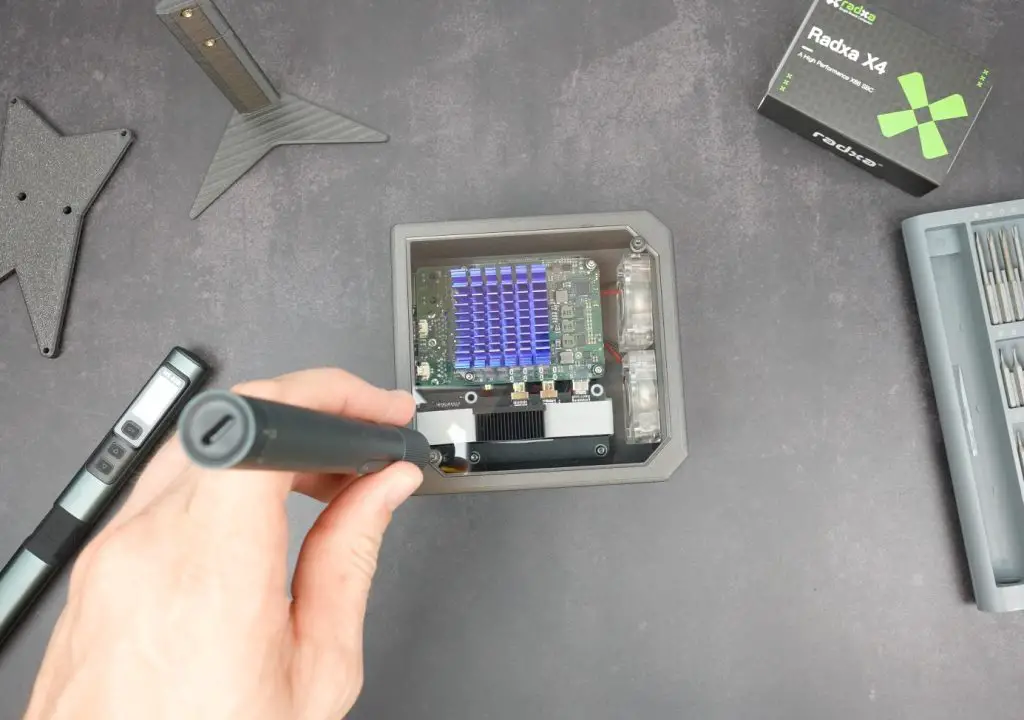
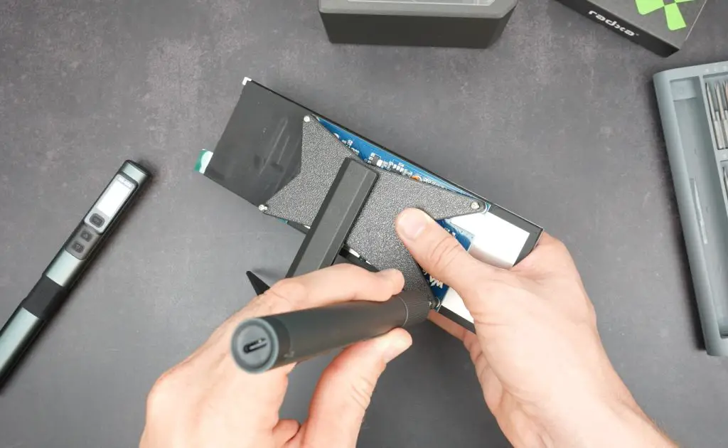
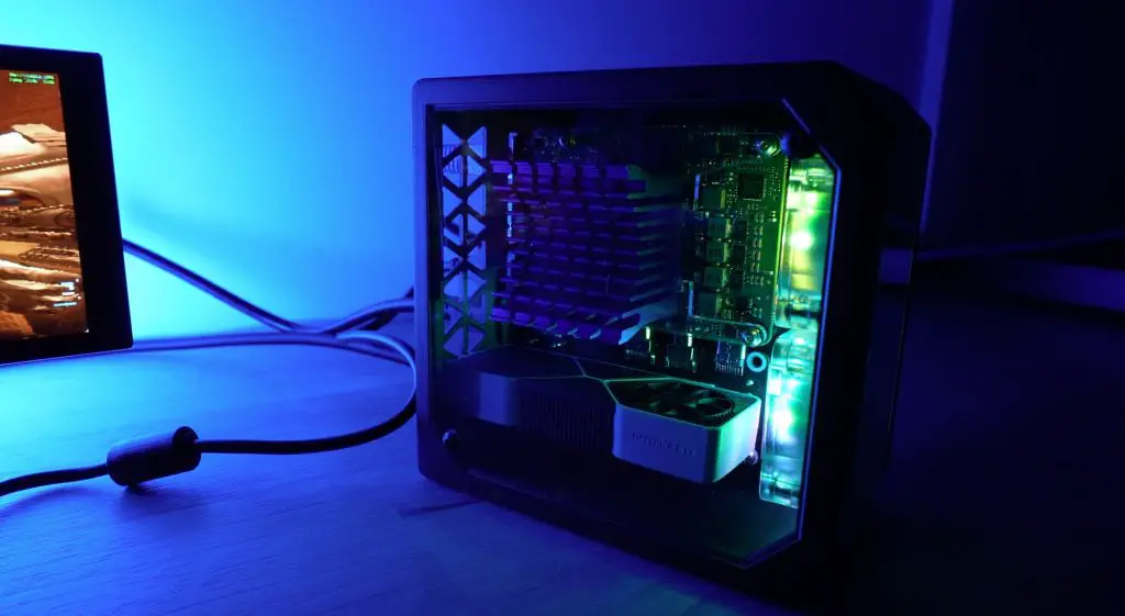
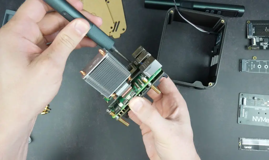
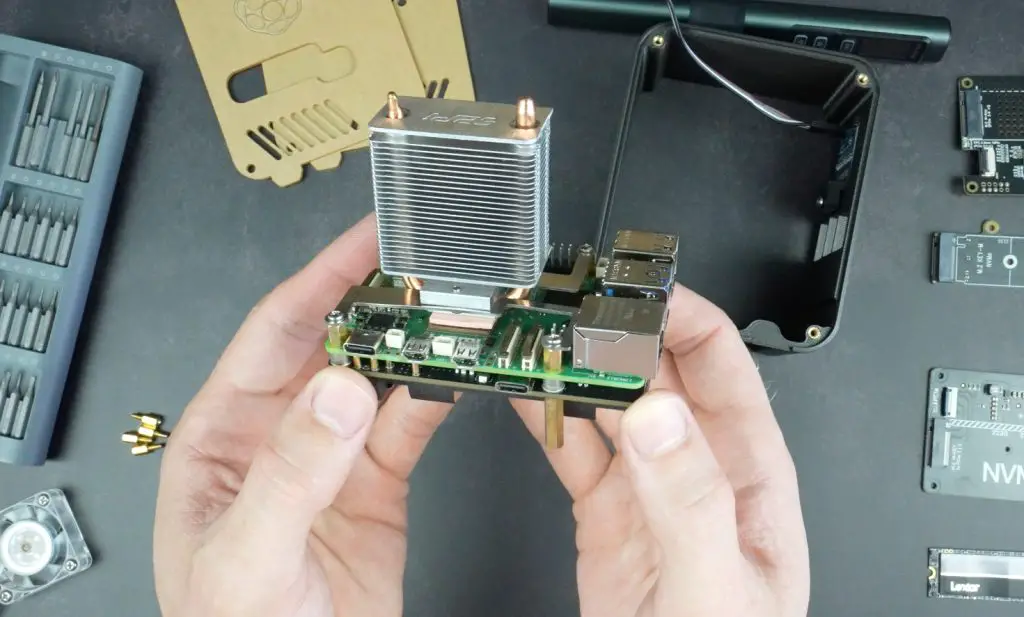
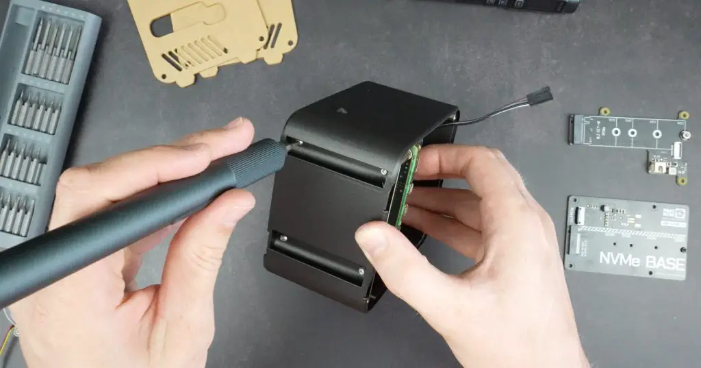
Taking A Look At The Internals
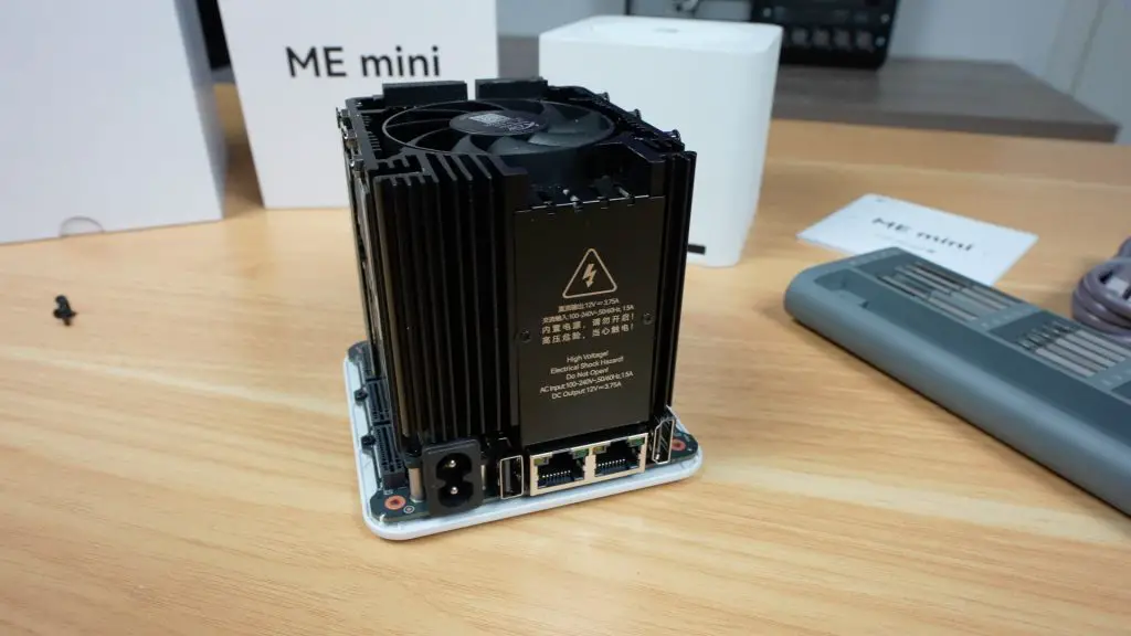
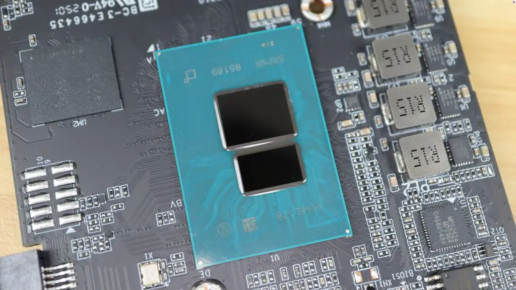
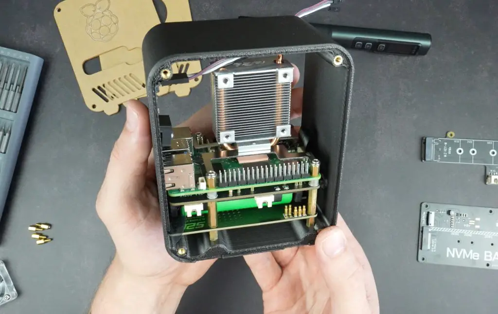
The main top cover is also easy to remove, secured with a single thumb screw. Inside, you’ll find the heart of the system, the Intel Core i9-13900HK, a 13th-gen Raptor Lake mobile CPU with 14 cores and 20 threads capable of boosting up to 5.4GHz.
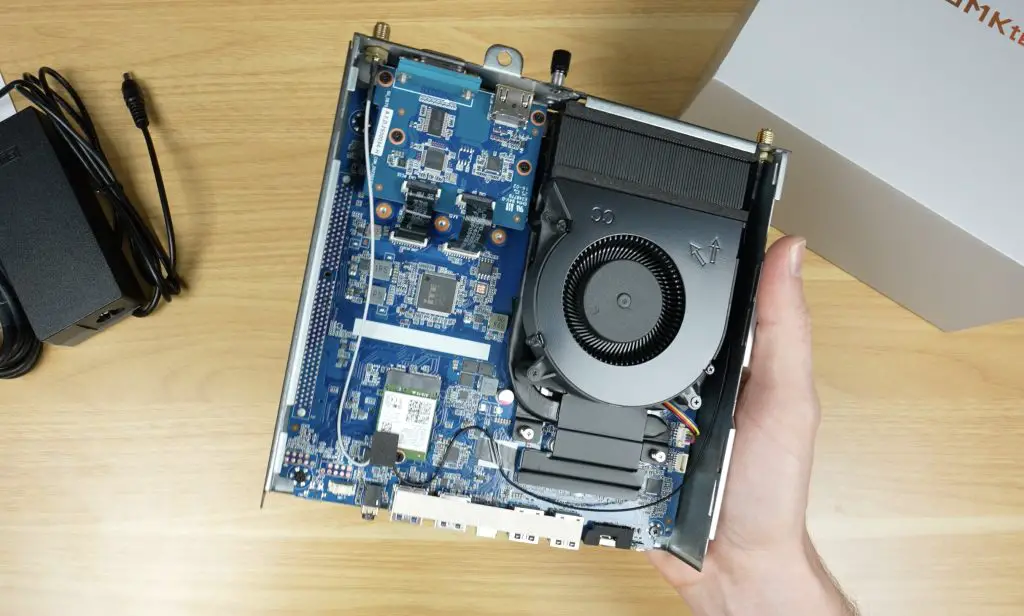
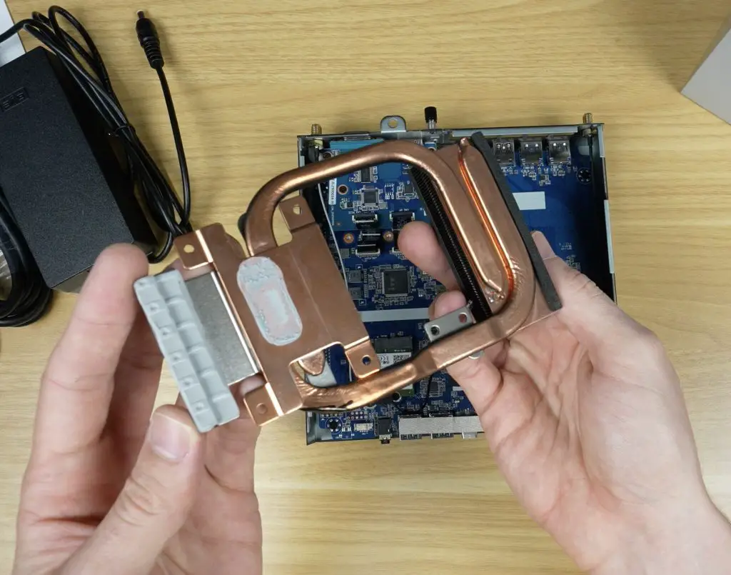
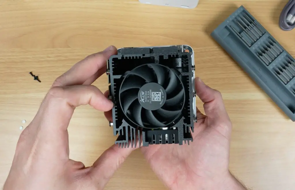
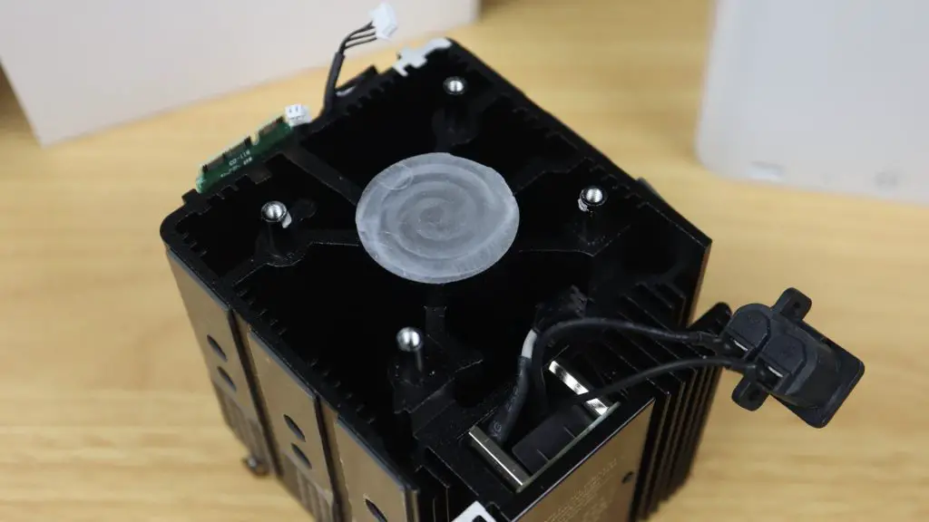
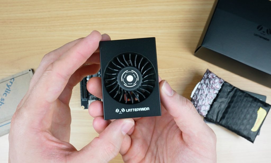
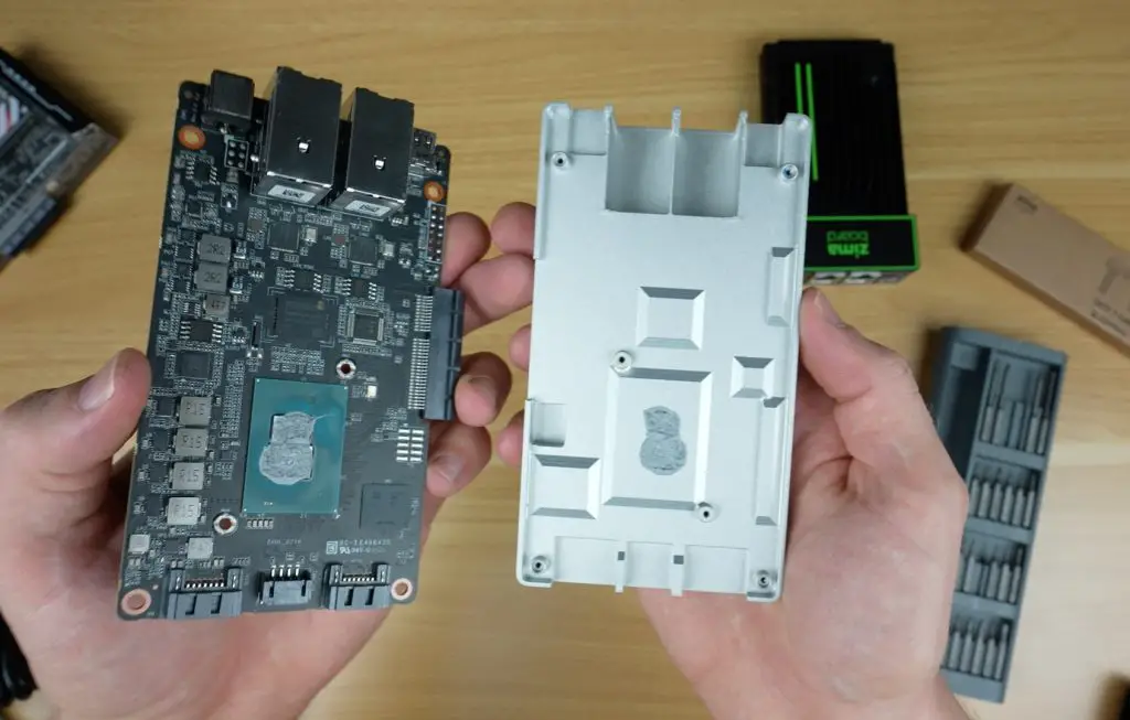
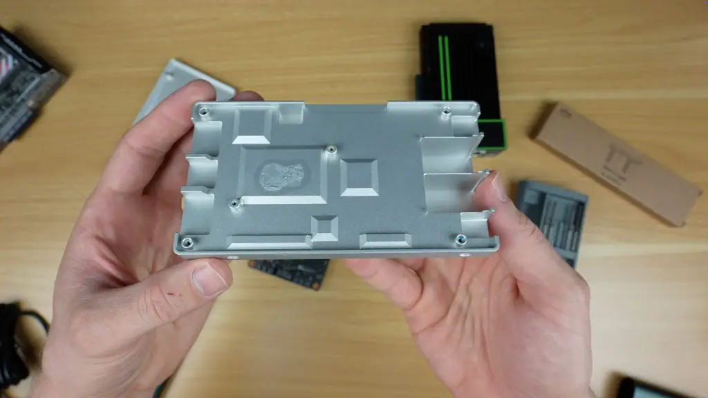
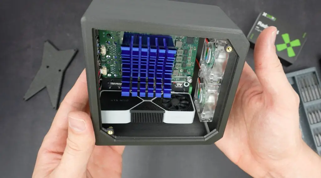
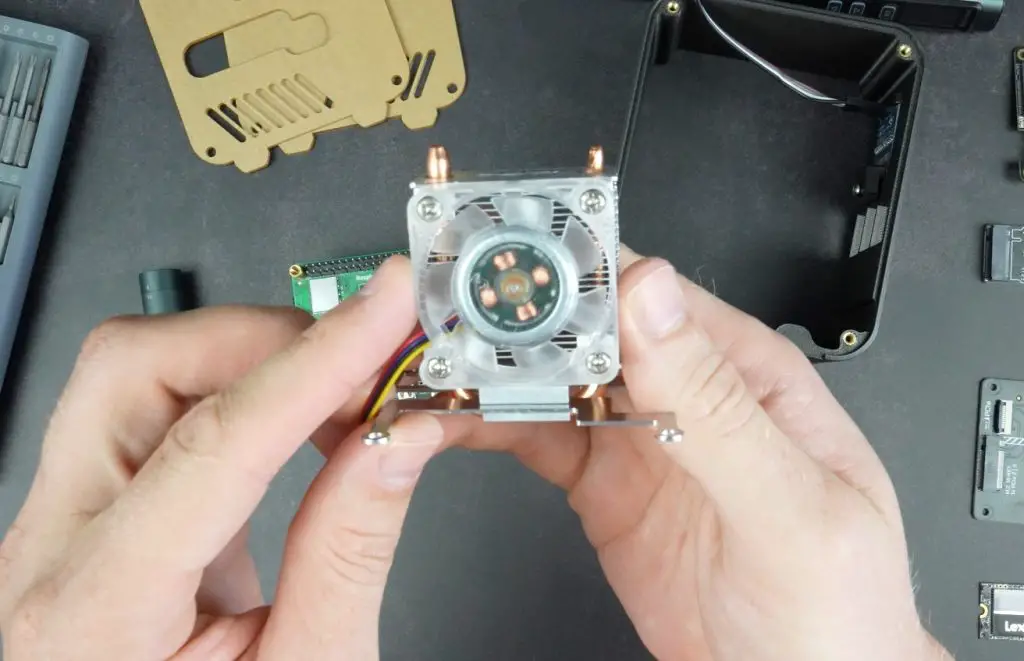
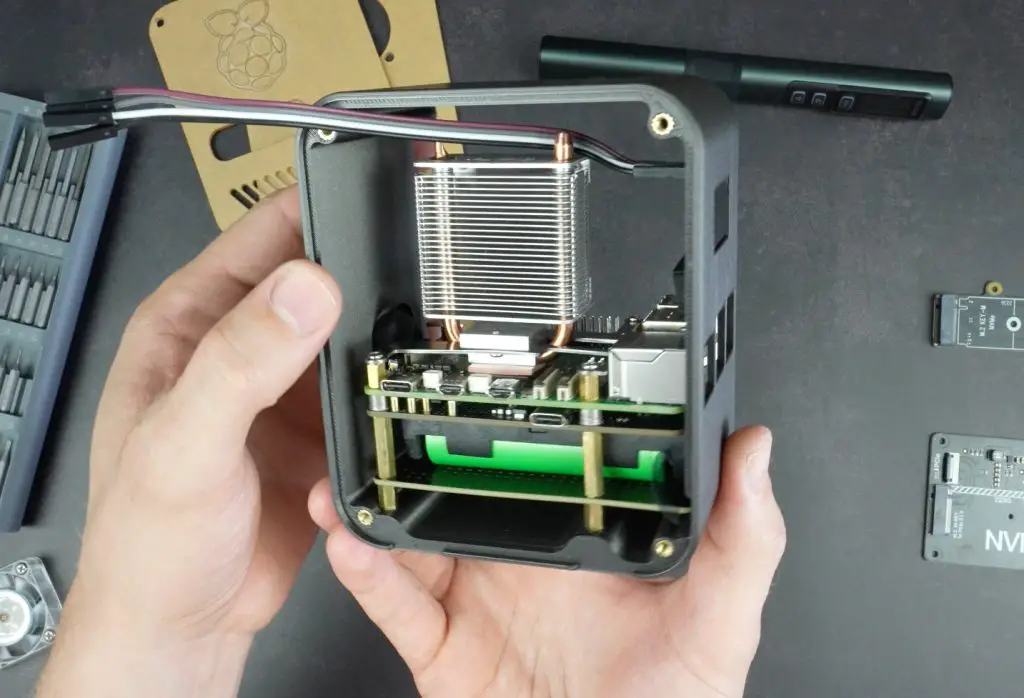
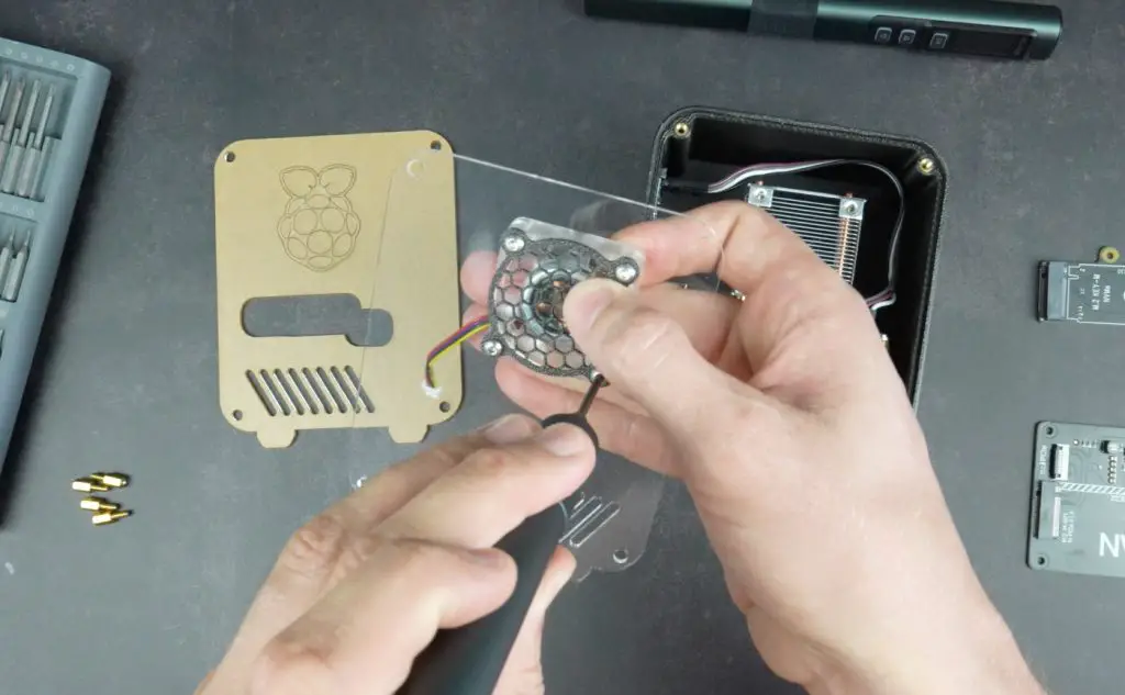
It’s quite a power hungry CPU, with a TDP of 45W, so hopefully the cooler is able to deal with this. The cooler is a full copper heat pipe design but since this is a mini PC, the cooler is quite compact. It does however have quite a large fan which should support better cooling and keep noise down.
The CPU includes Intel Iris Xe integrated graphics with 96 execution units, running at up to 1.5GHz. This will likely be limitating for GPU-heavy tasks or gaming. That said, for media playback, light editing, or basic 3D applications, it should hold up reasonably well.
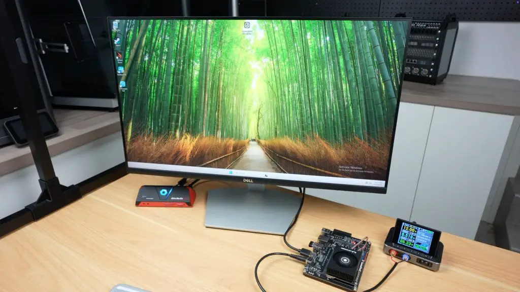
First Boot & Performance Testing
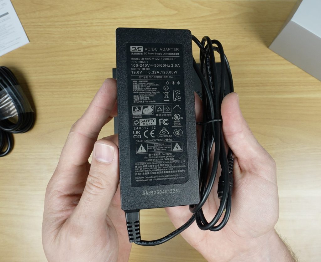
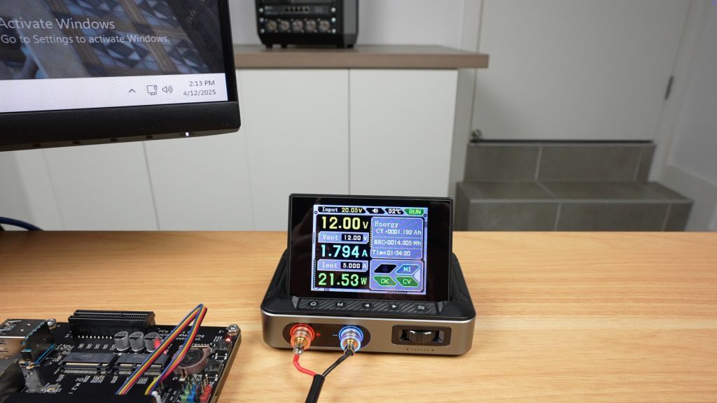
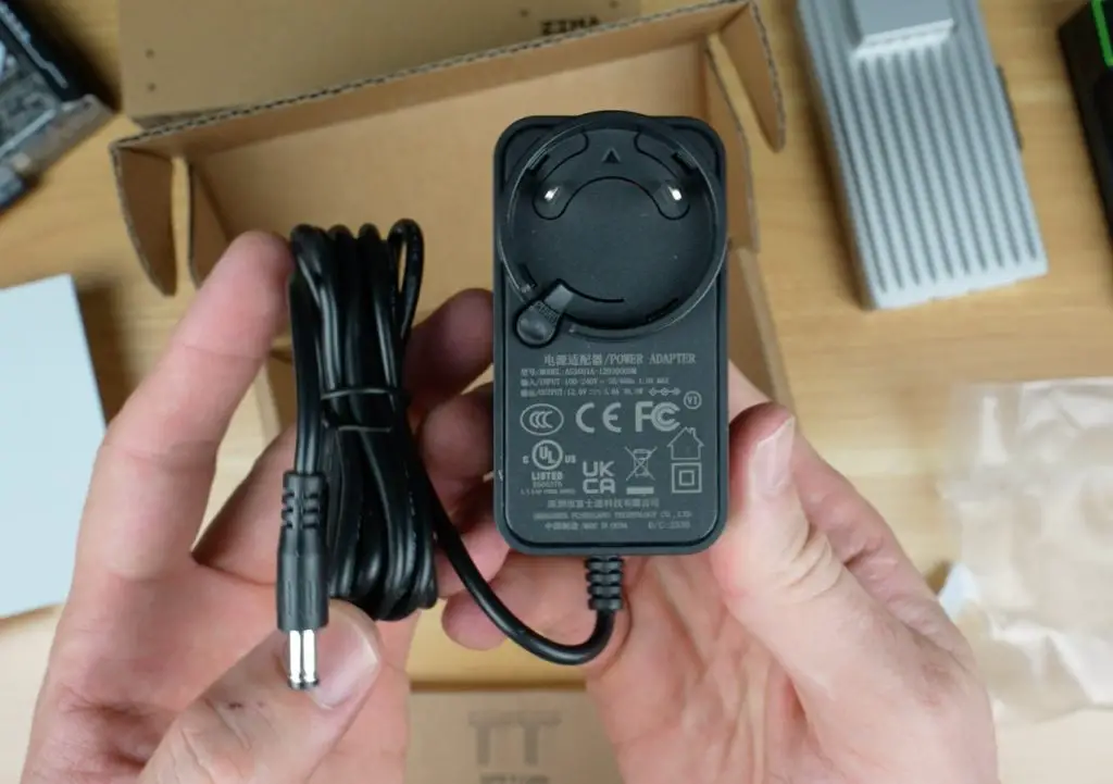
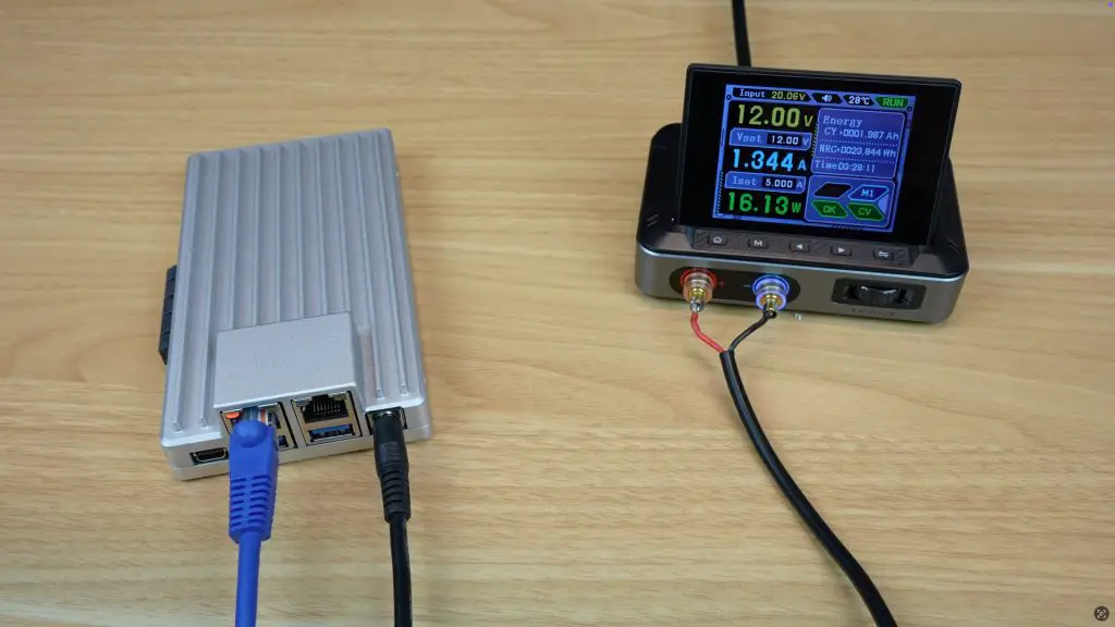
The included power adapter outputs 19V at 6.32A, totaling 120W, which is higher than most mini PCs but necessary for this level of performance.
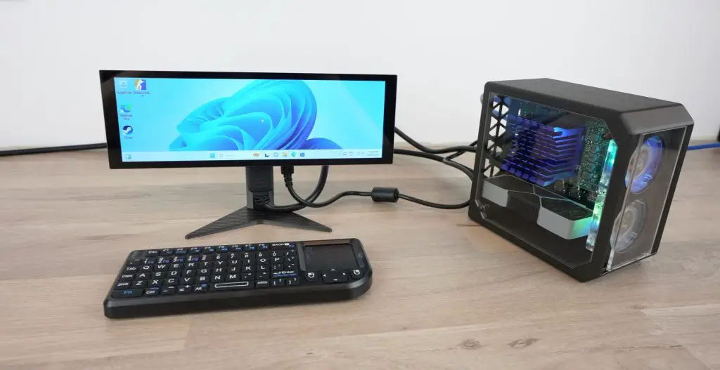
The K10 ships with Windows 11 preinstalled, and the installation appears to be clean with no bloatware.
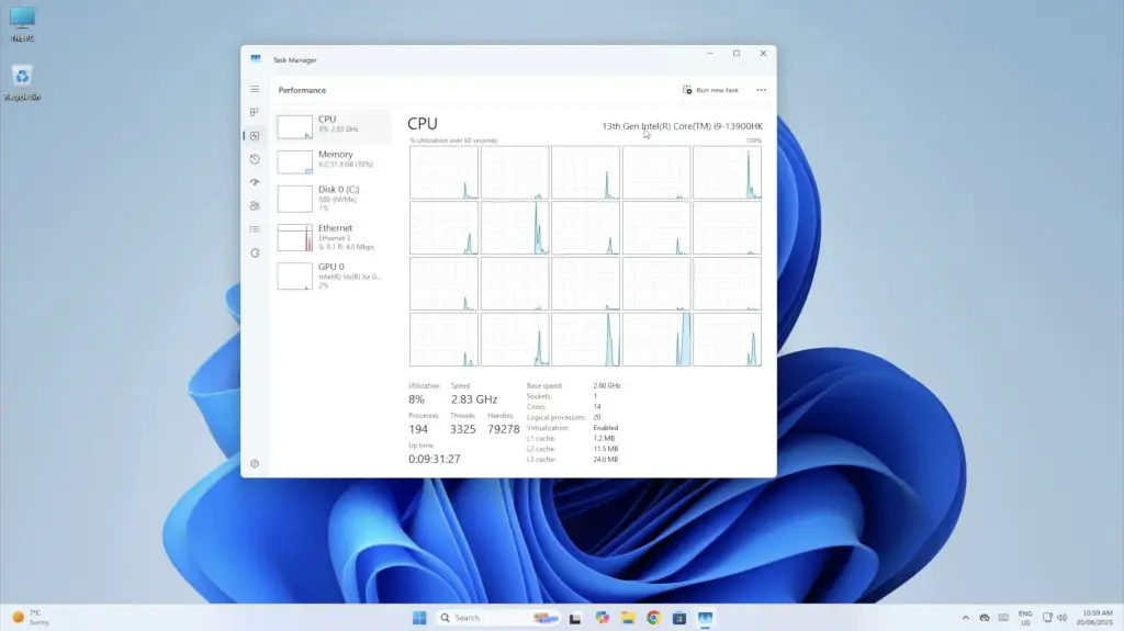
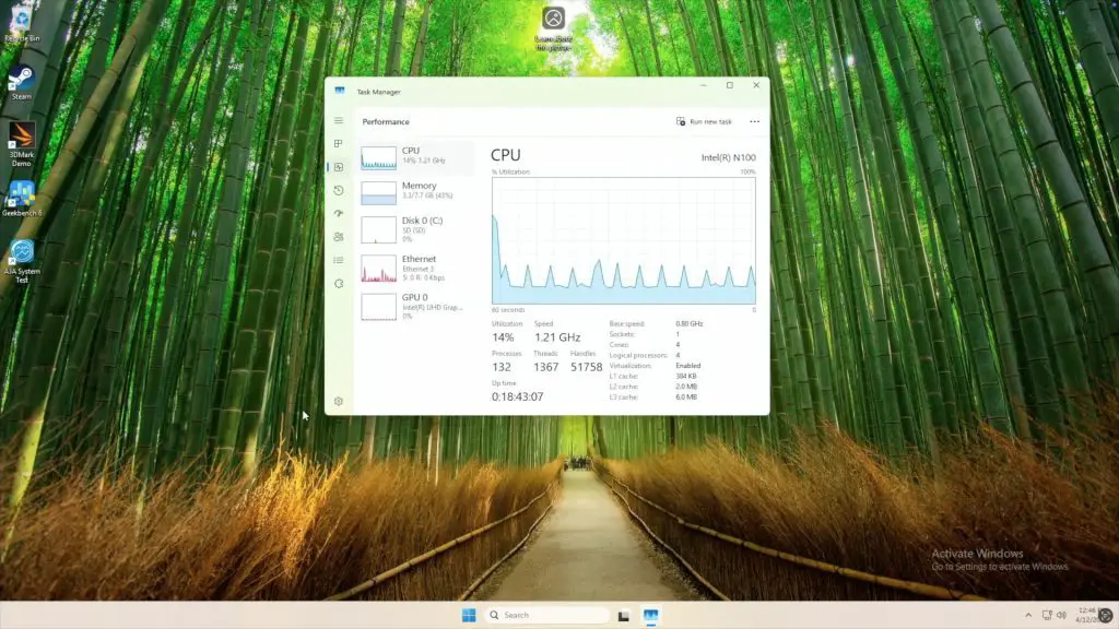
Opening Task Manager confirms the specs:
- Intel Core i9-13900HK with 20 threads
- 32GB DDR5 RAM @ 5200MHz
- 1TB Crucial NVMe SSD
- Intel Iris Xe iGPU with 16GB shared memory
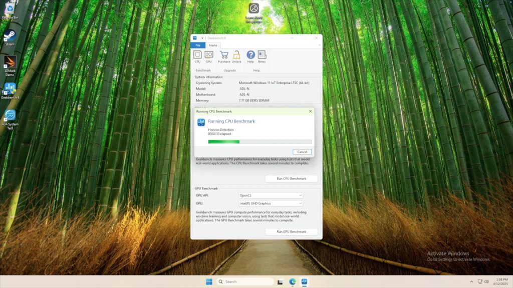
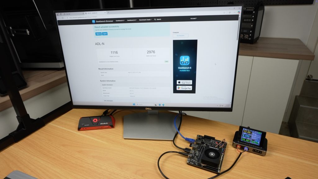
Geekbench CPU Benchmark
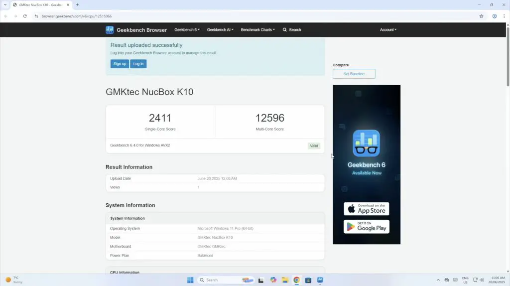
Running a Geekbench CPU Benchmark yields solid results:
- Single-core score: 2,411
- Multi-core score: 12,596
- Averaged over three tests: 2,514 and 12,606 respectively
These scores are pretty good for a mini PC, and would beat some more modern Core Ultra 7 series PCs.
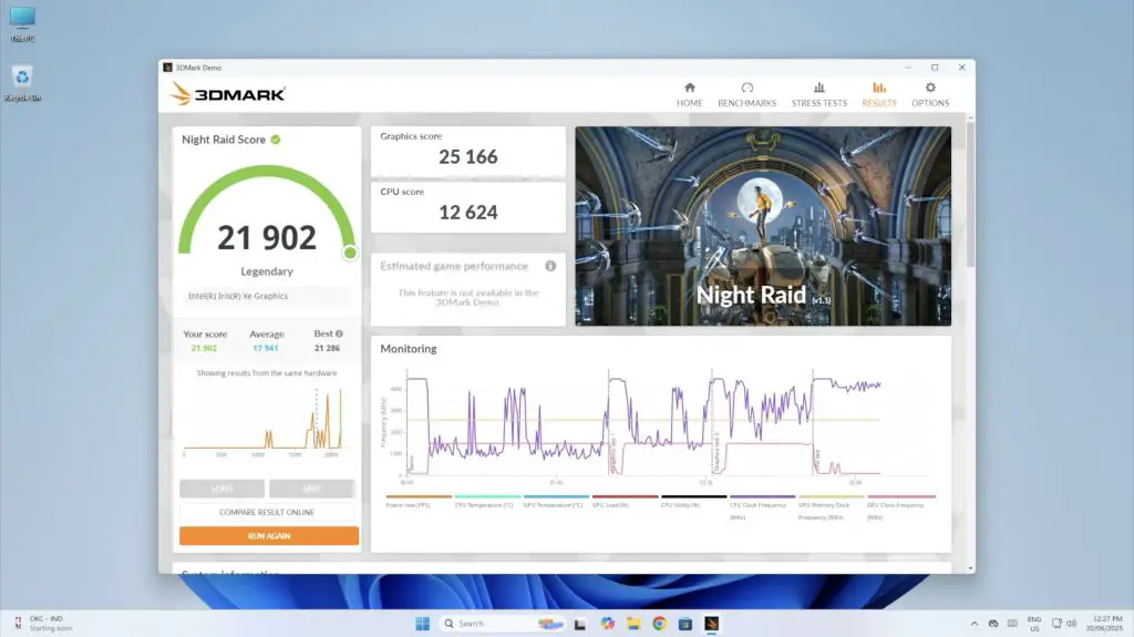
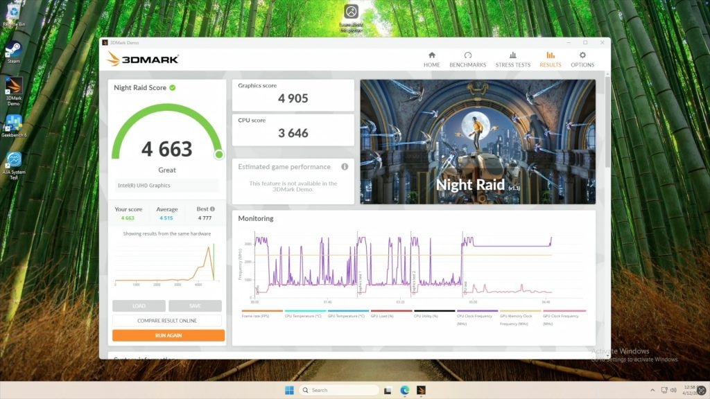
3DMark Night Raid GPU Benchmark
In 3DMark Night Raid, designed for integrated GPUs:
- Overall score: 21,902
- Graphics score: 25,166
- CPU score: 12,624
The graphics score is near the top end of what is achievable with this iGPU and is far better than older UHD graphics. It’s likely good enough for low to medium settings on less demanding games but won’t be good for any modern games. The CPU score is also quite good.
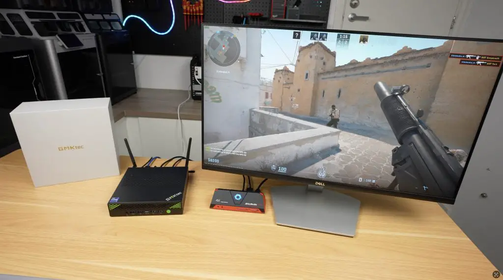
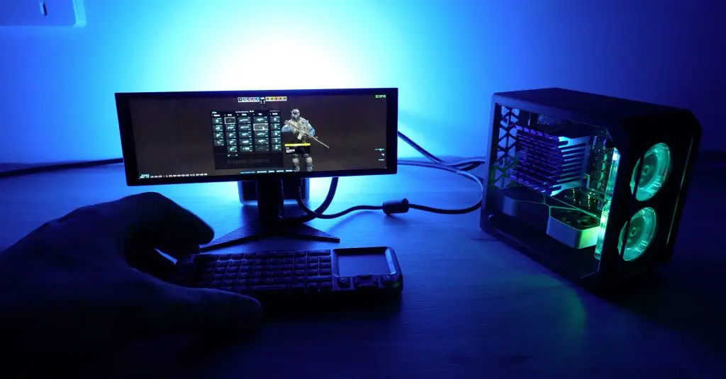
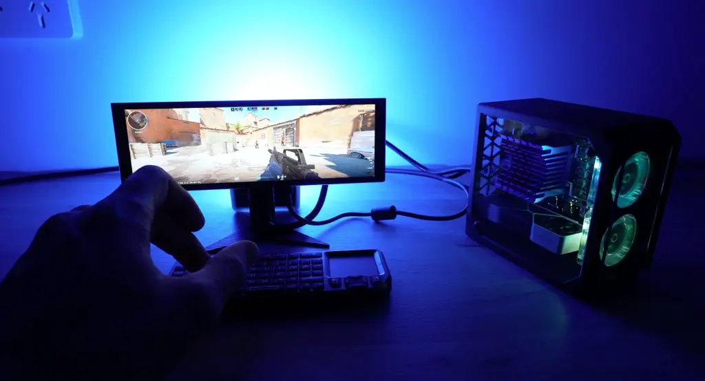
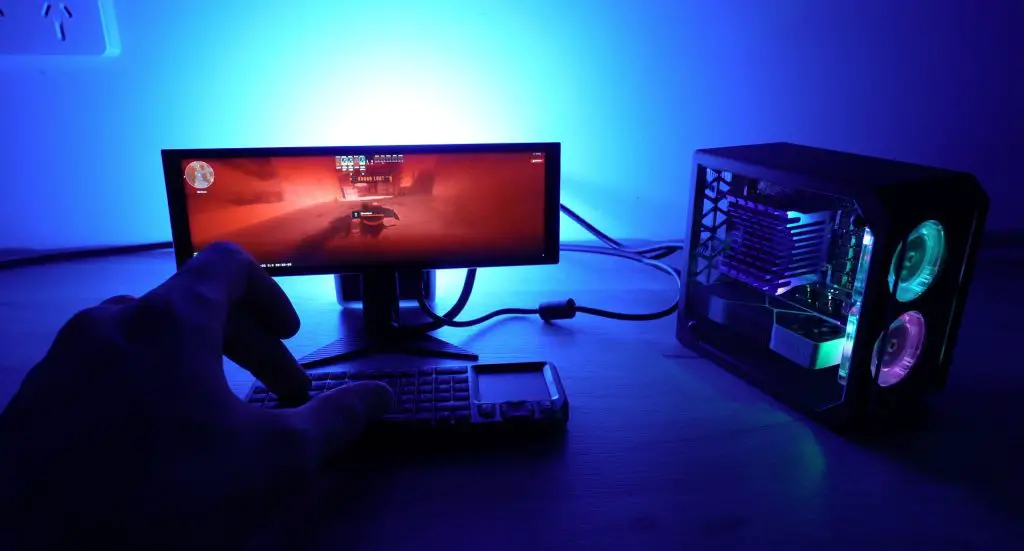
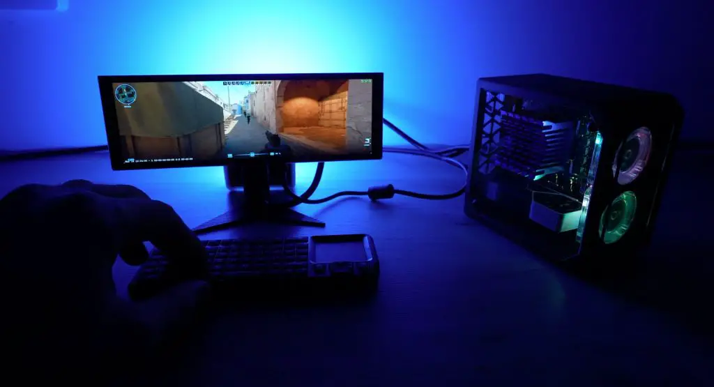
Gaming Test: Counter-Strike 2
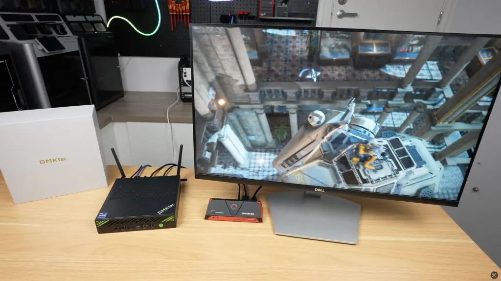
I then tried running counterstrike 2 on it to see how the GPU performed. And, as expected, it’s not great for gaming. At 1080P with graphics on medium settings we get about 75fps. This is usable but I expected a bit more. The GPU is very much the bottleneck for this PC. With graphics set to very high this goes down to 30fps.

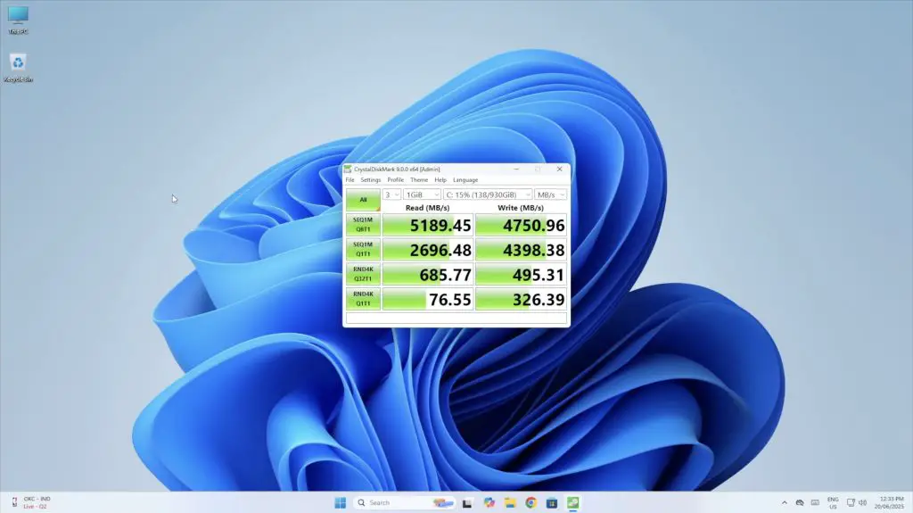
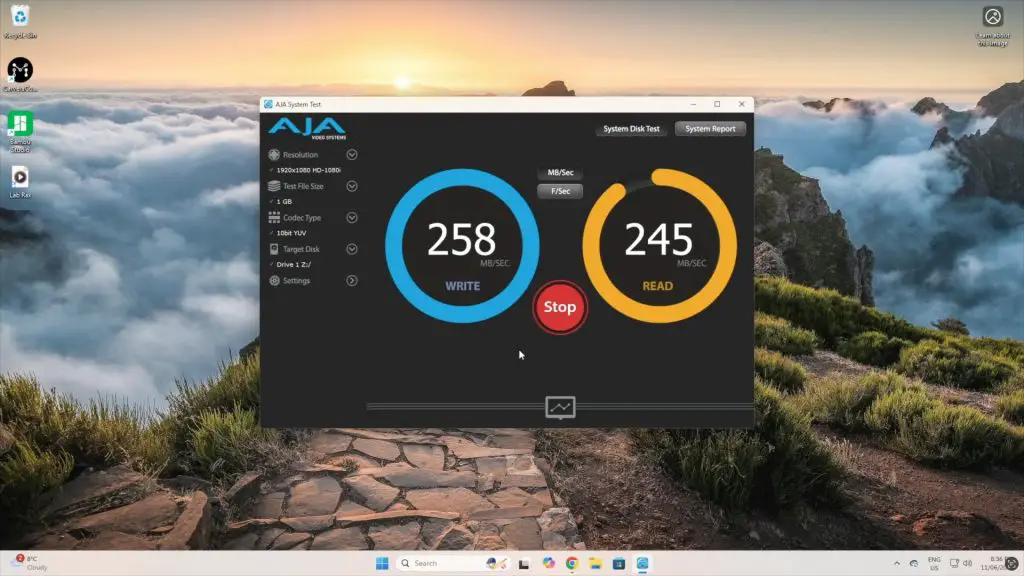
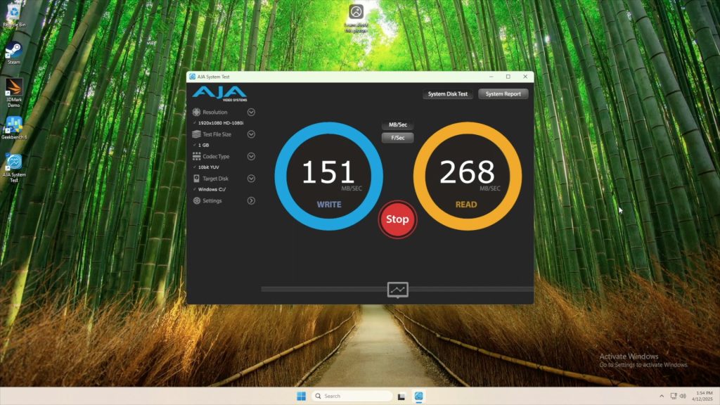
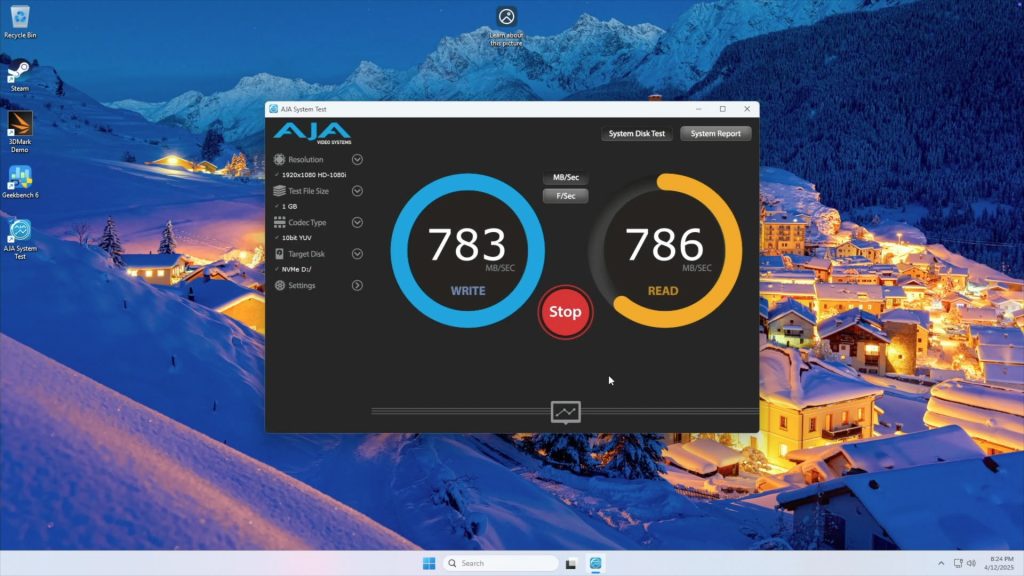
Storage Performance
Testing the Crucial P3 Plus SSD with a 1GB test file:
- Read speed: ~5190 MB/s
- Write speed: ~4750 MB/s
These are expected figures for a PCIe Gen 4 x4 interface with a DRAM-less budget drive.
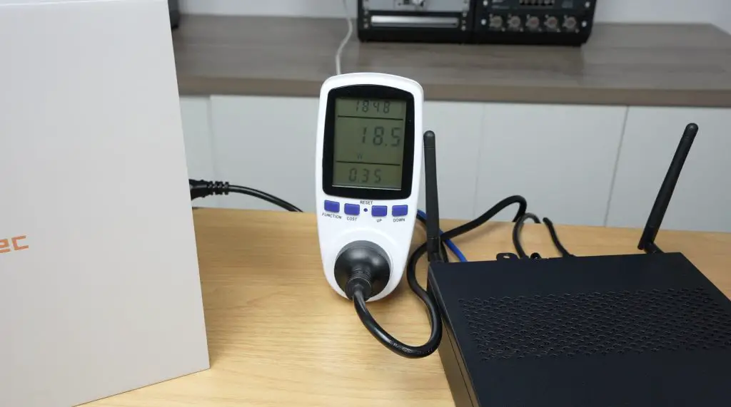
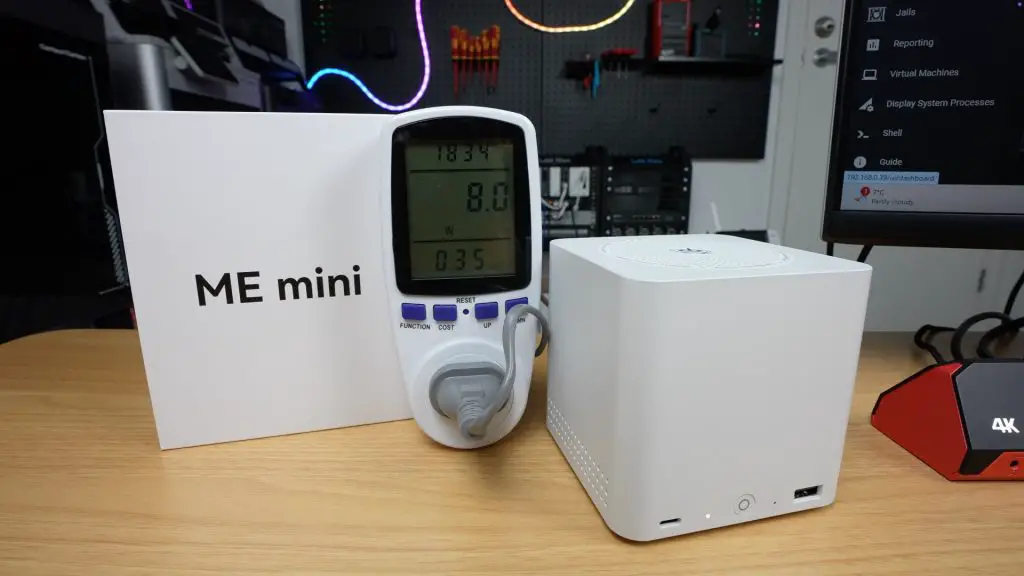
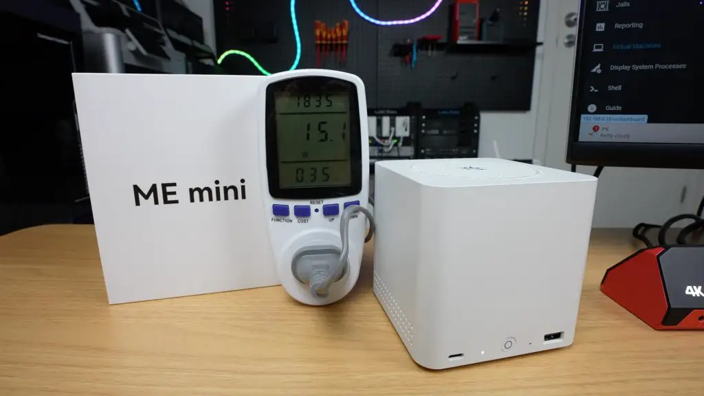
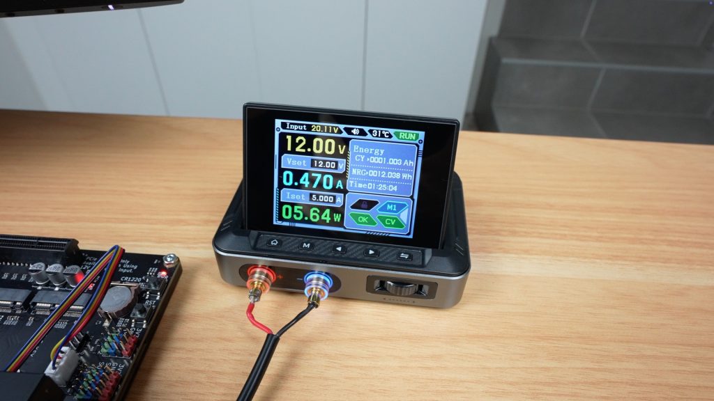
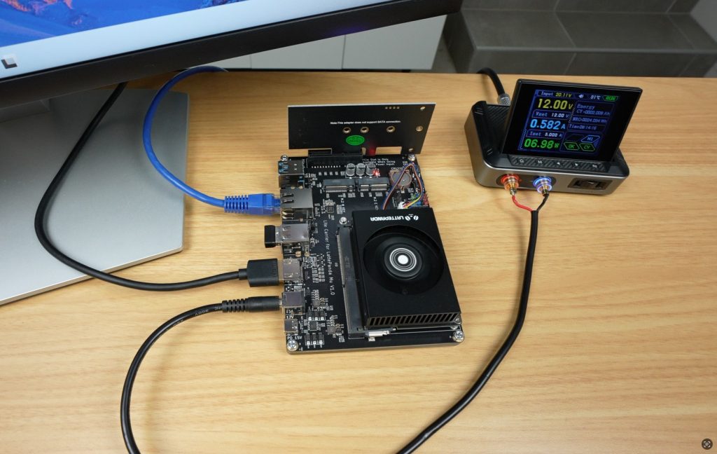
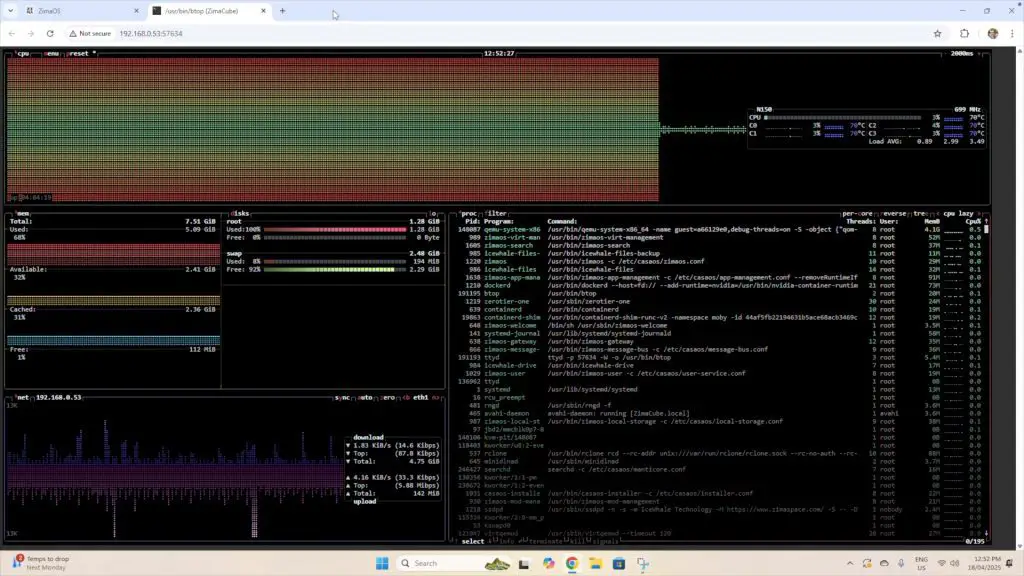
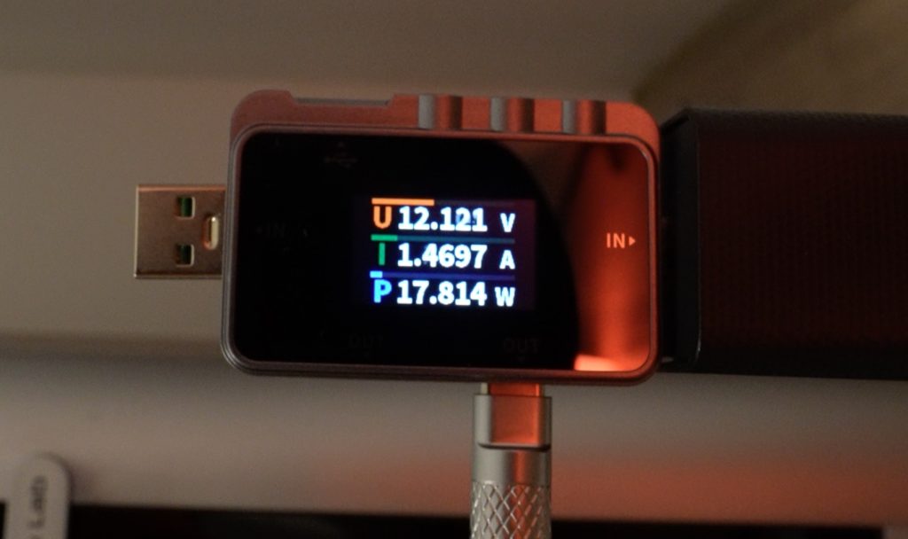
Power Consumption
- Idle: 18W
- Full load (CPU + GPU): 84W
While this is high for a mini PC, it’s still much more efficient than a desktop with comparable specs. The performance-per-watt is excellent.

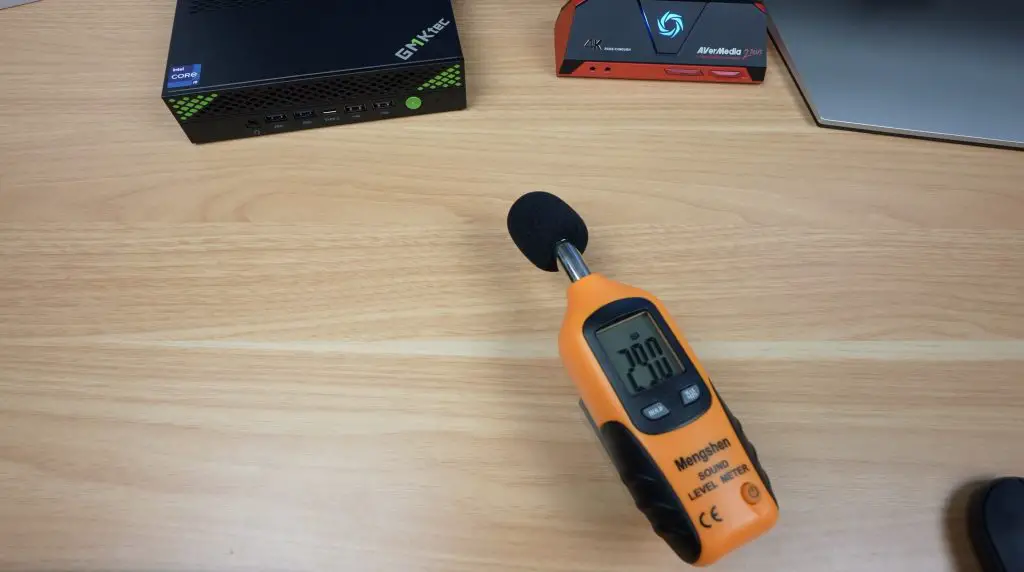
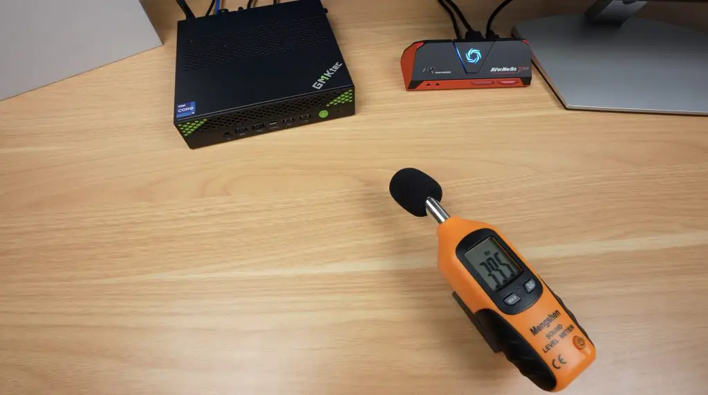
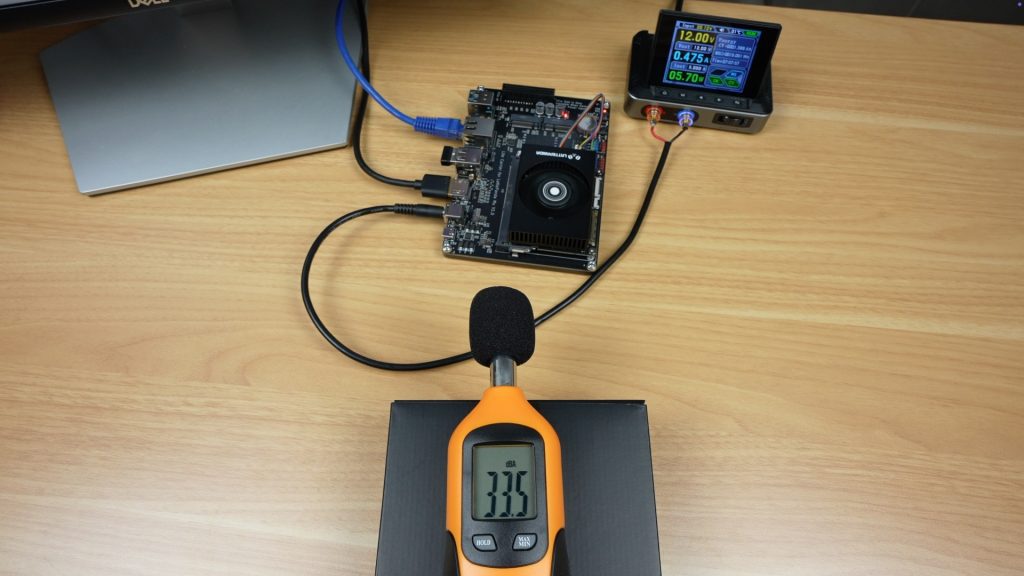
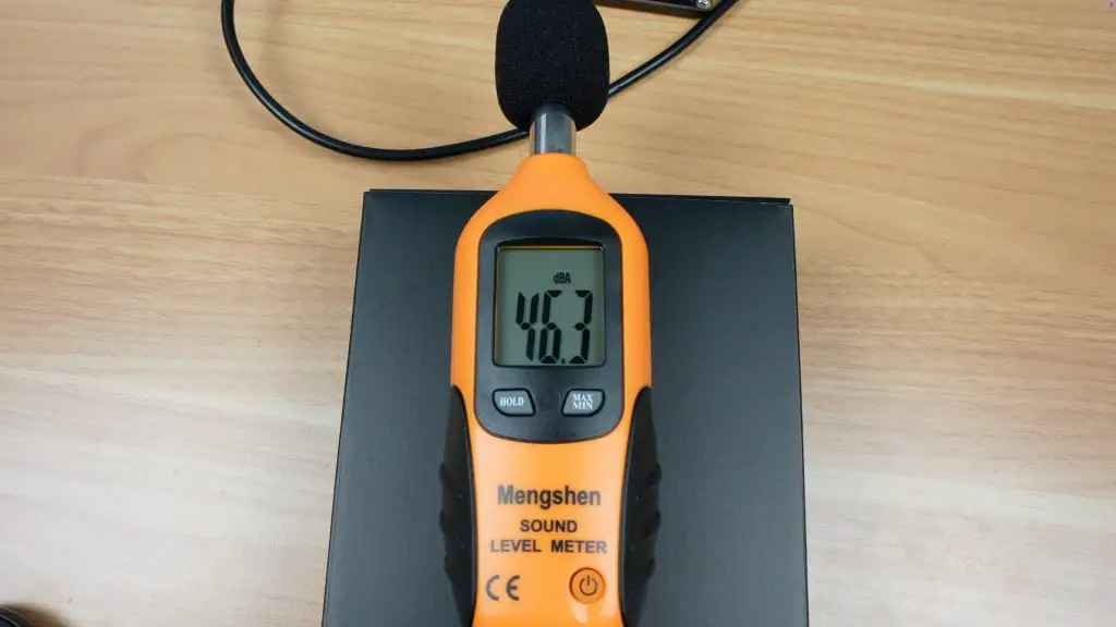
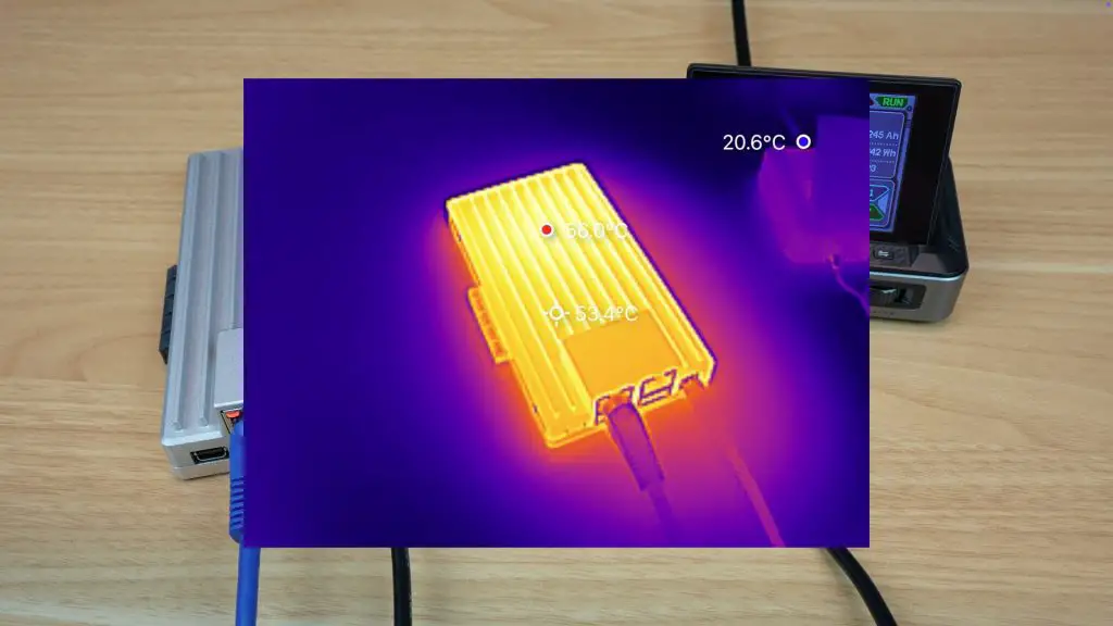
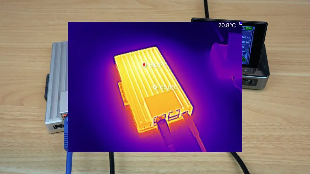
Fan Noise & Sound Level
Throughout benchmarking and gaming I was pleasantly surprised by how quiet the fan was. It’s barely audible at idle and only slighter louder when full loaded.
- Idle: 30dB
- Full load (CPU + GPU): 39dB
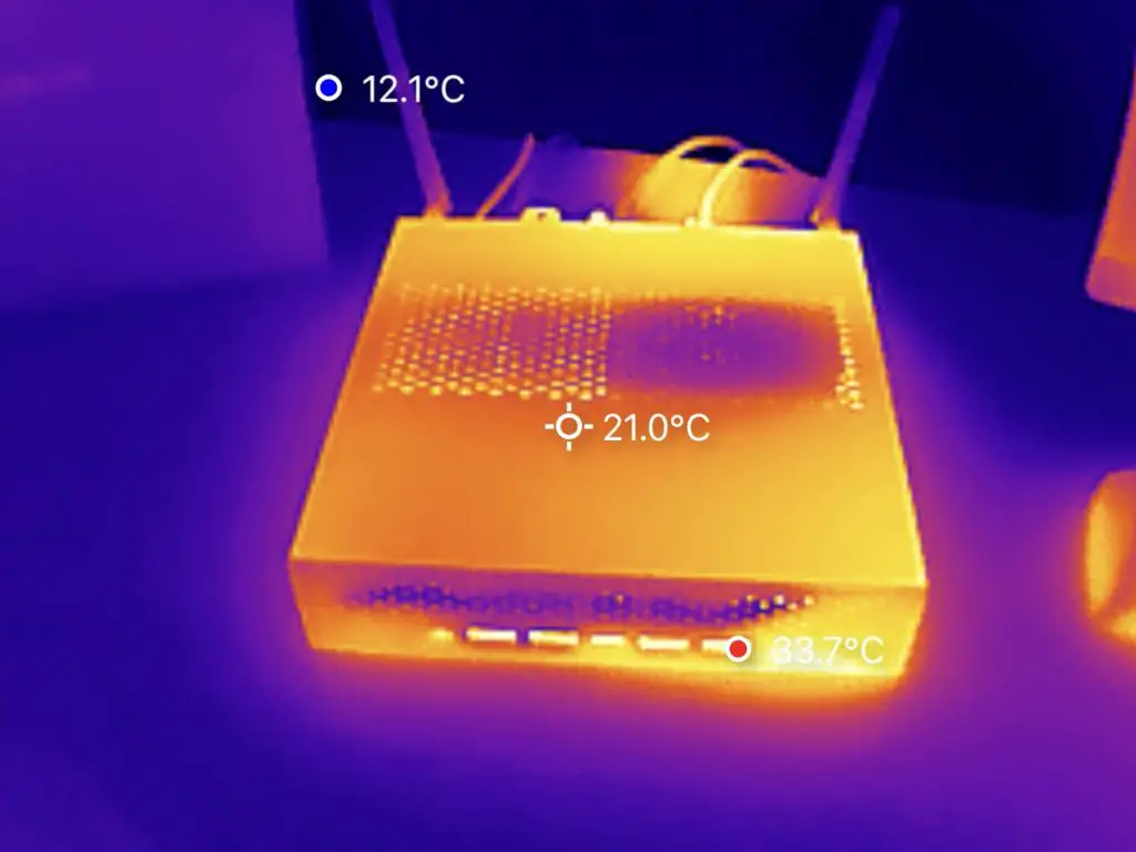
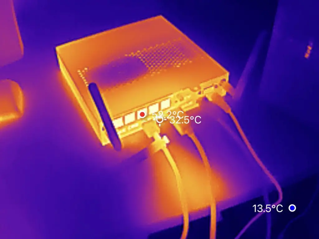
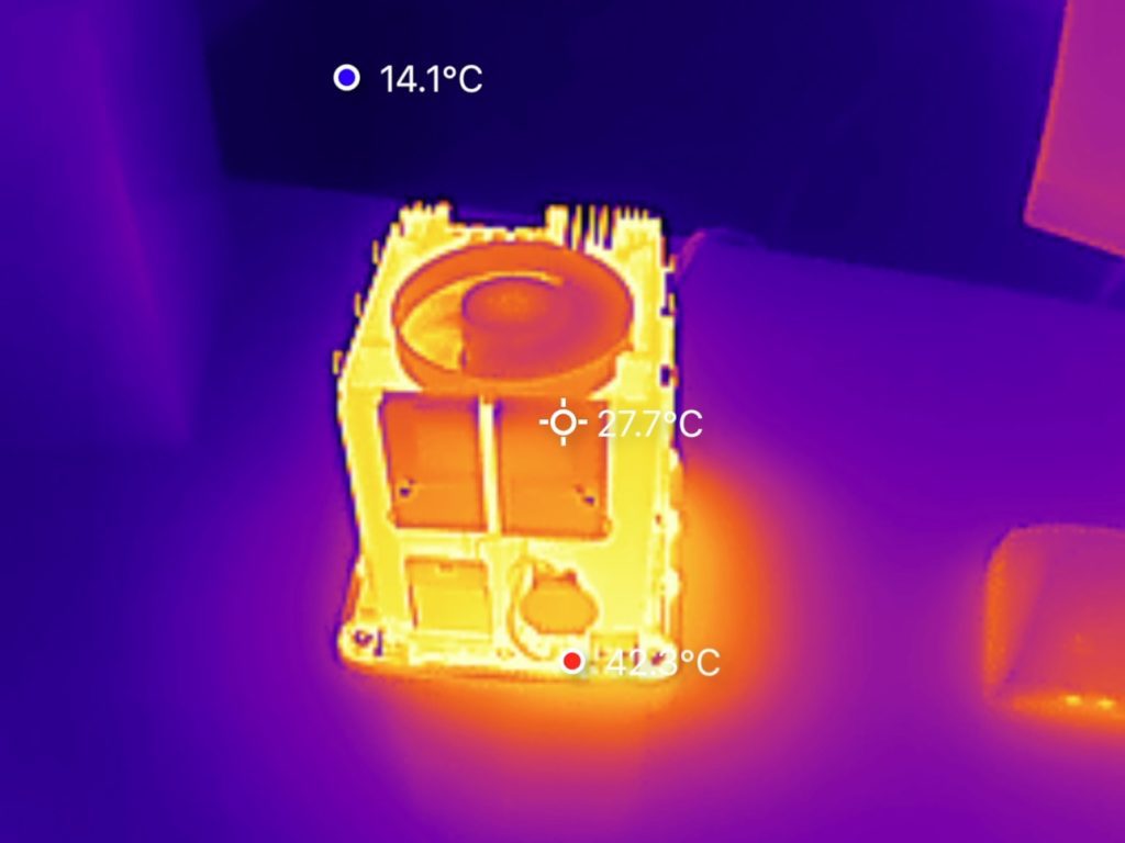
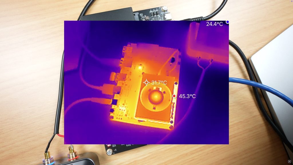
The fan also does a good job at keeping the CPU cool, even under full load the CPU didn’t go over 60 degrees.
Final Thoughts On The GMKtec NucBox K10
The GMKtec NucBox K10 delivers an impressive balance of power, upgradability, and quiet operation in a compact form factor. It’s not a gaming rig, but it excels as a homelab server, media center, or productivity workstation.
Pros:
- Powerful 14-core i9 processor
- Toolless design for easy upgrades
- Quiet under load
- Generous IO selection
- Excellent storage and RAM options
Cons:
- GPU performance limits gaming
- Higher power consumption than most mini PCs
- Lacks USB 4 support
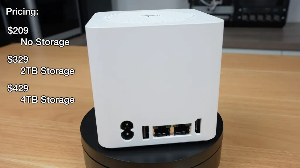
In terms of pricing, on the GMKtec website, the barebones PC with no RAM or SSD installed is $420, this goes up to $590 with 64GB of RAM and a 1TB SSD installed. You can also often find them on sale on Amazon, so have a look there first.
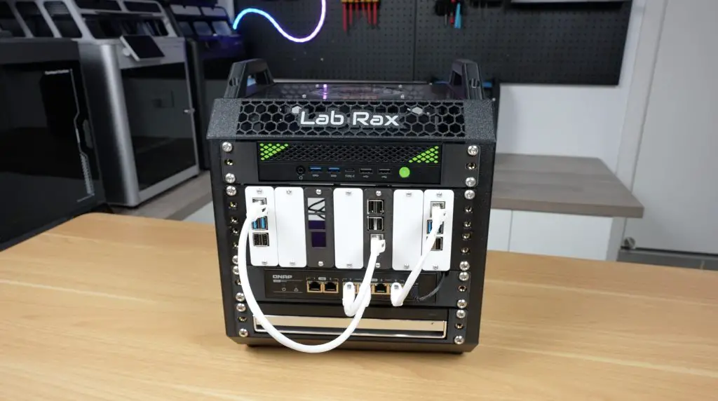
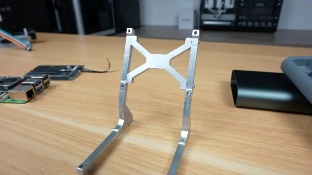
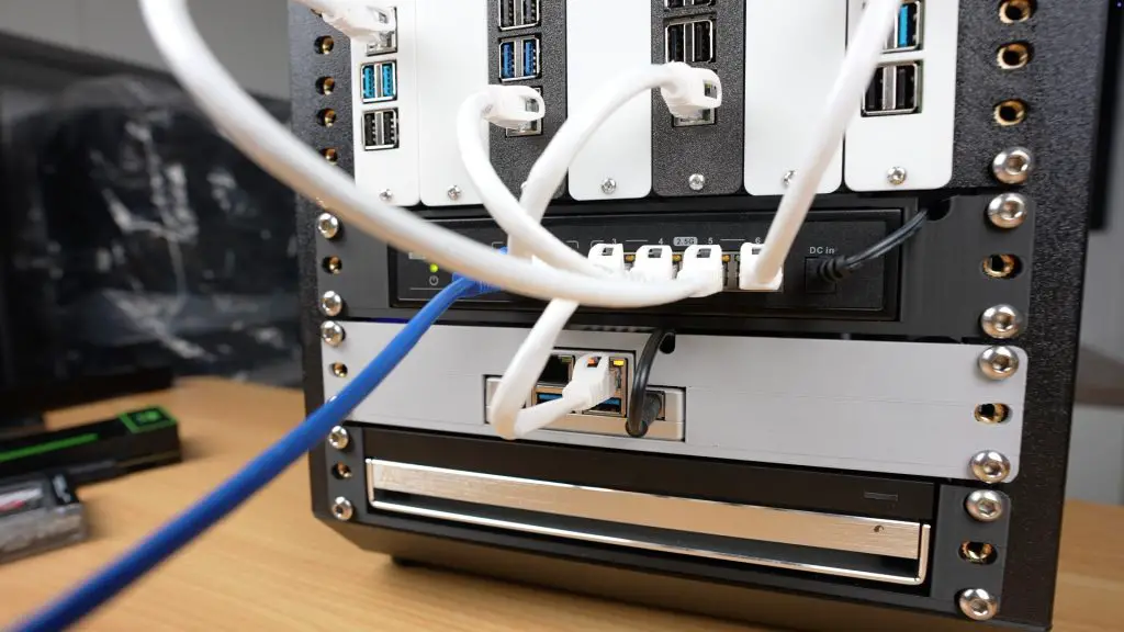
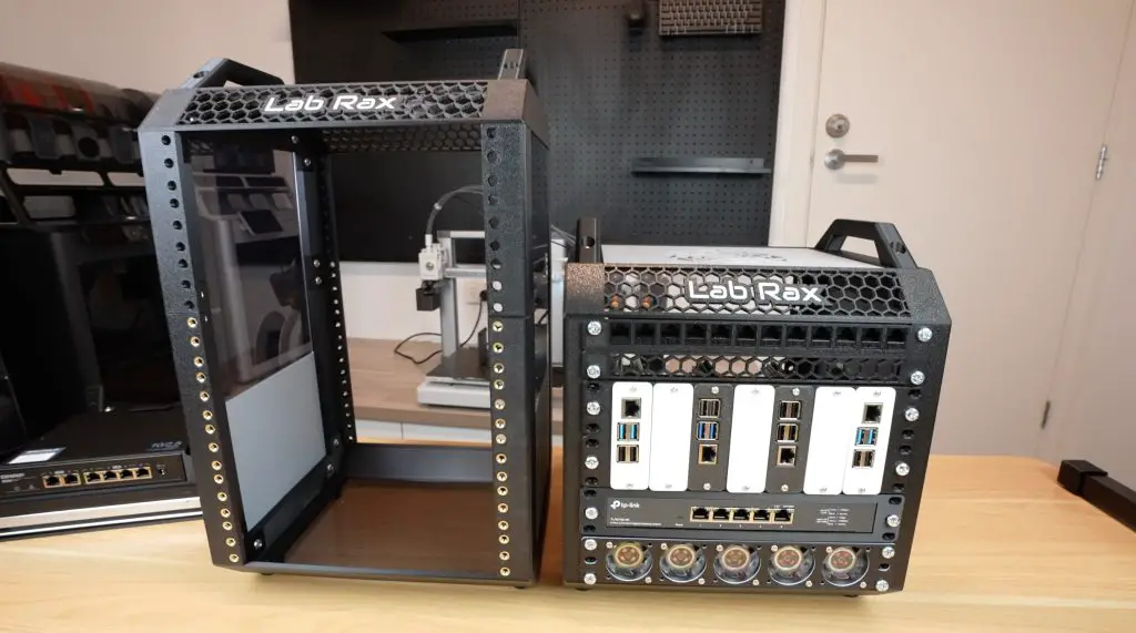
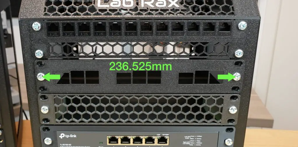
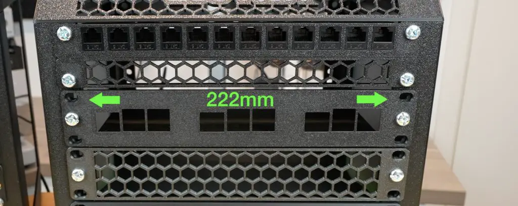
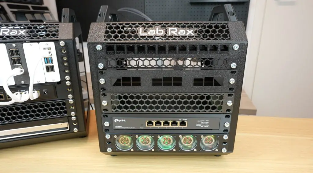
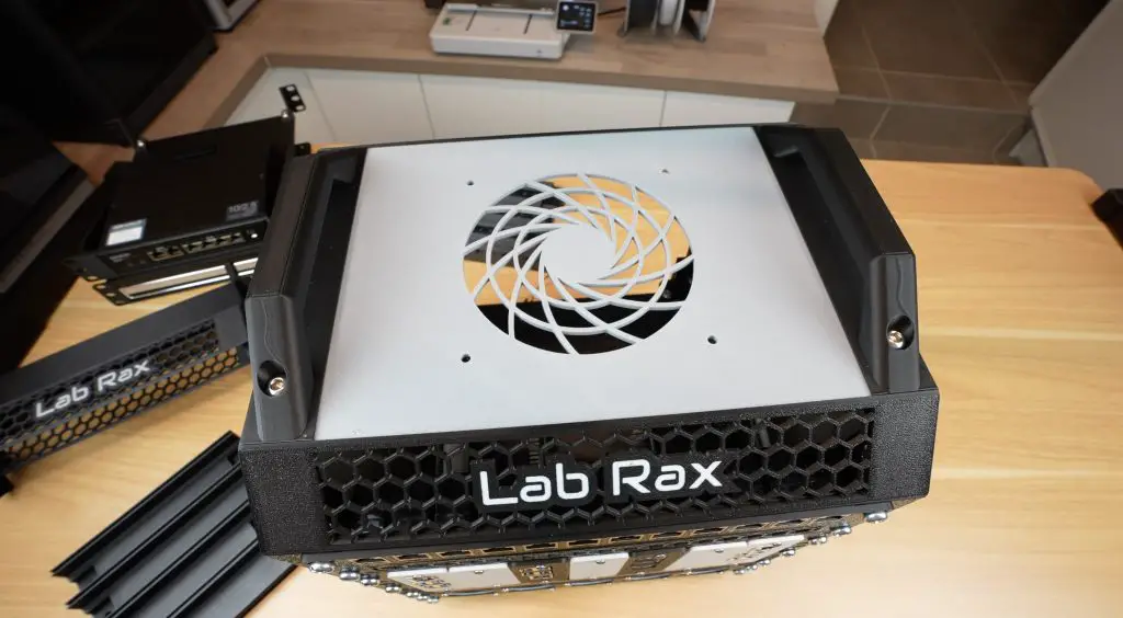
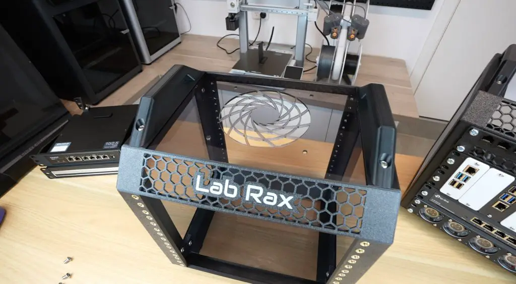
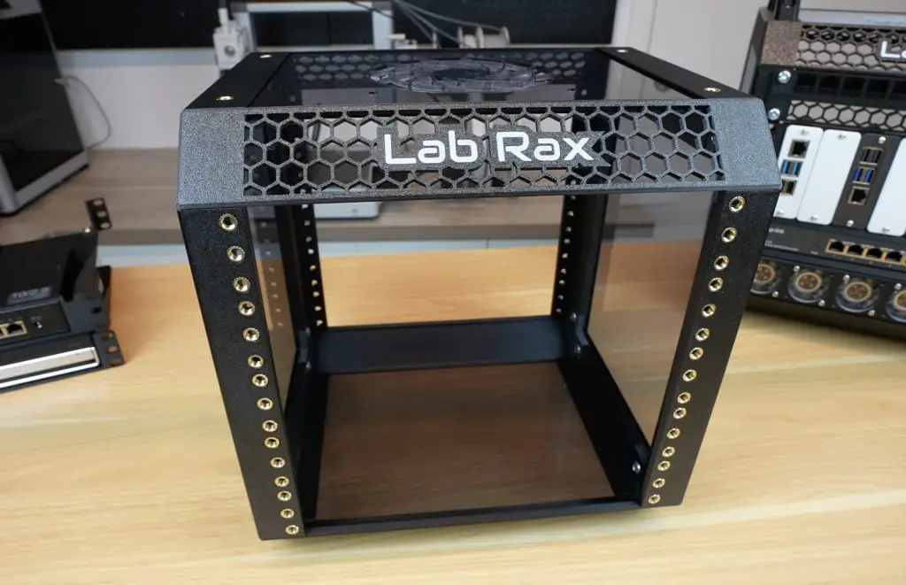
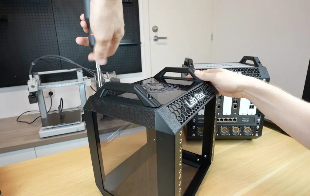
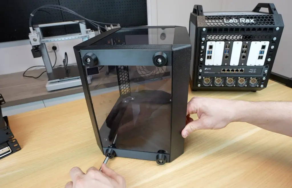
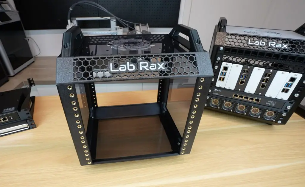
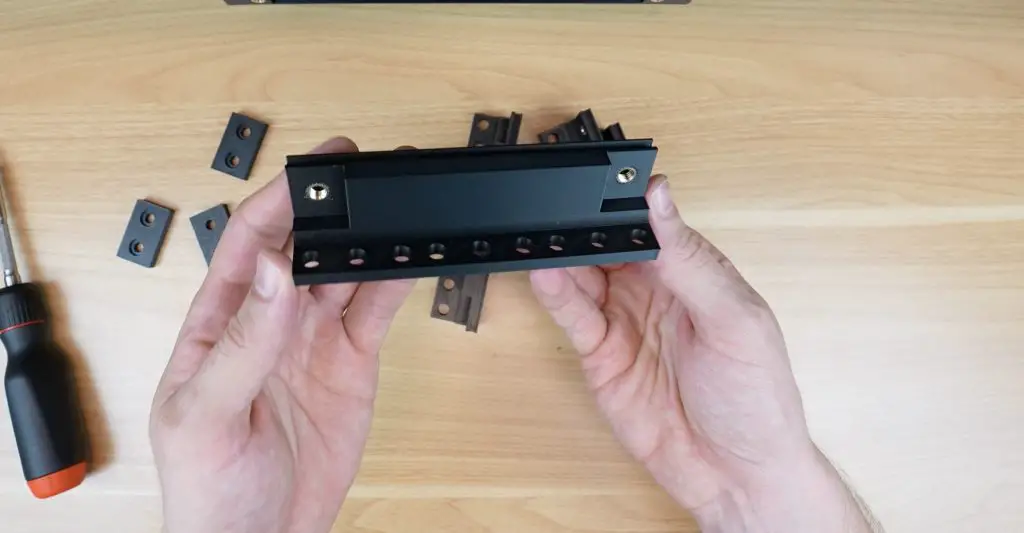
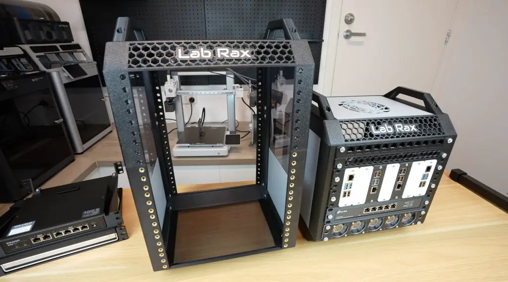
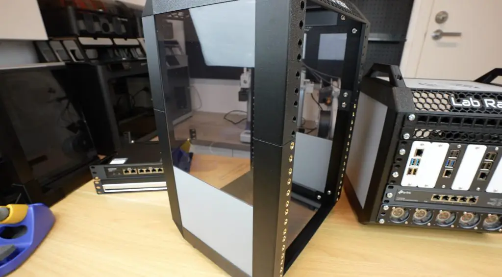
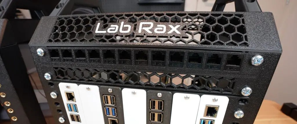
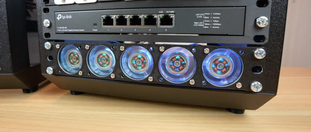
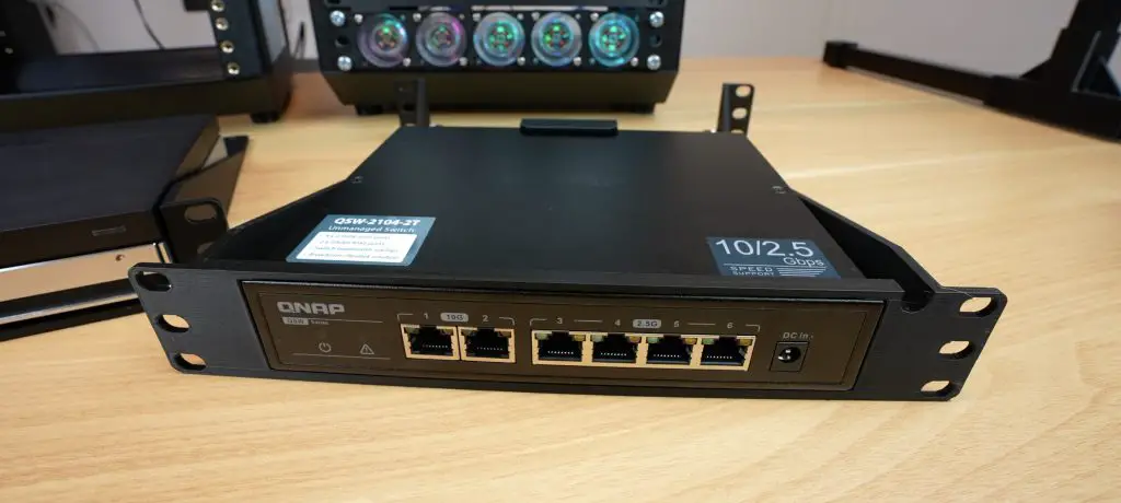
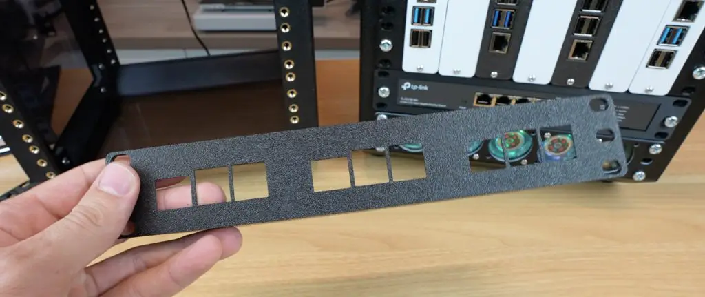
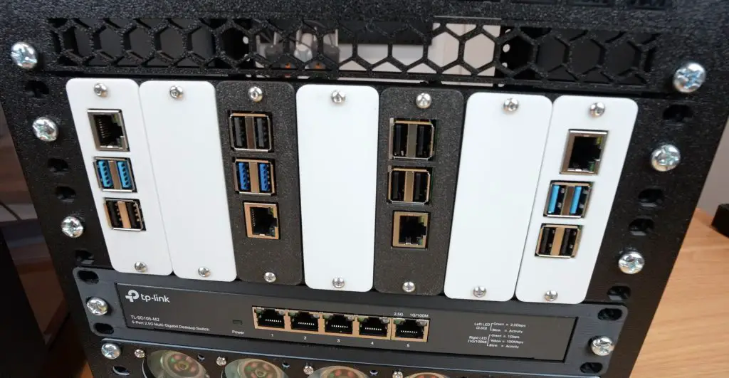
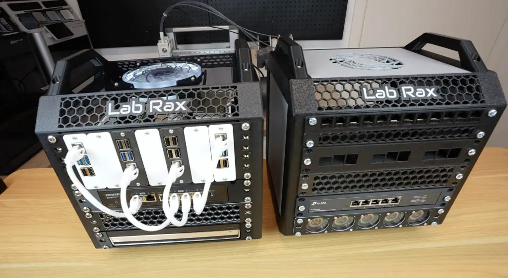
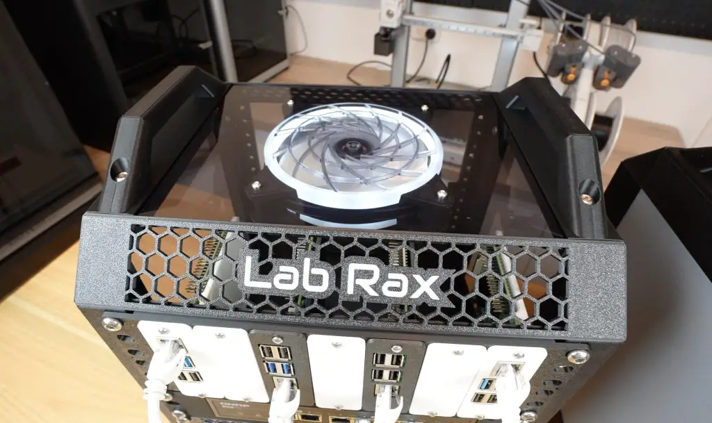
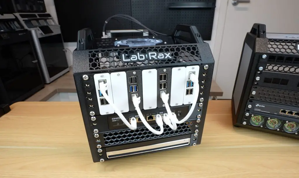
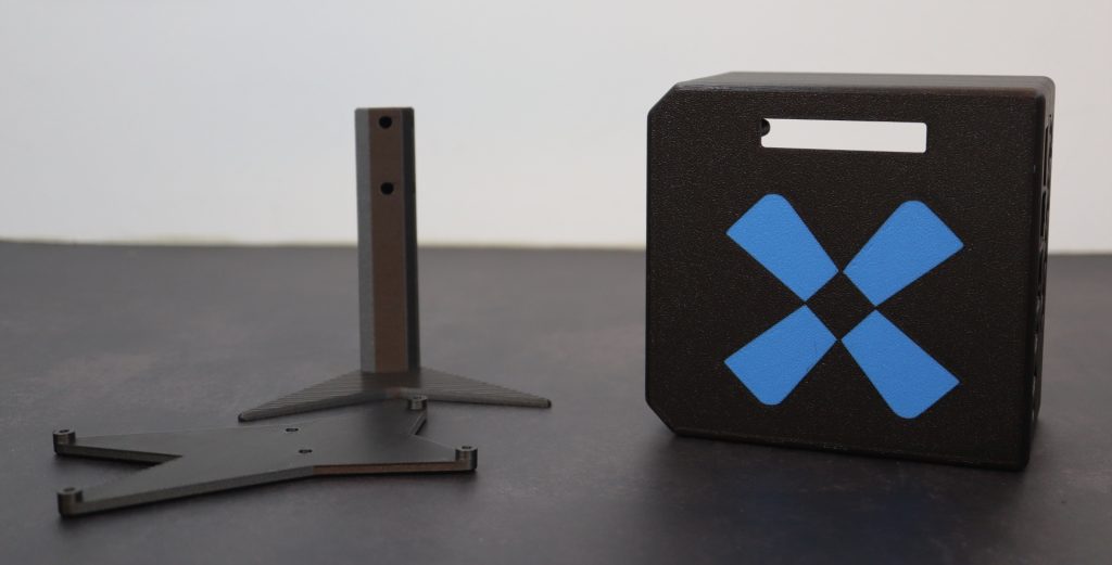
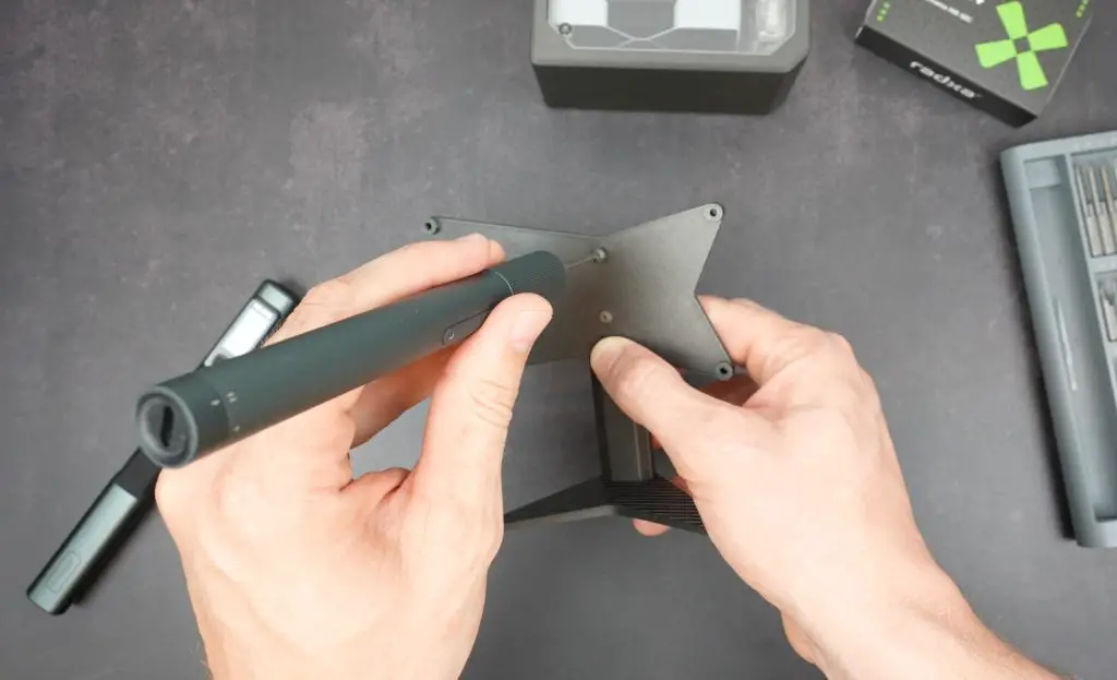
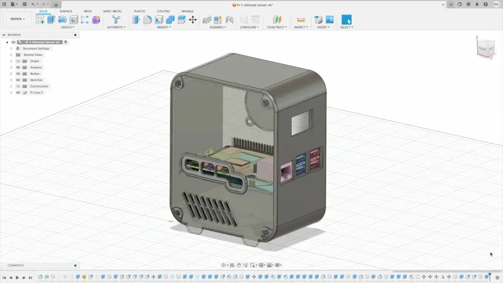
For those who need a quiet, powerful, and compact system, the K10 is a great value, especially if you’re building out a homelab. I’ve already added mine to my 3D printed Lab Rax setup.
Let me know what you think of the NucBox K10 in the comment section below and if there’s anything else you’d like to see me test on it.


")


