In this project, we’re going to be making an all-in-one indoor air quality monitor with an IOT dashboard using an infrared CO2 sensor from DFRobot and a BME280 environment sensor.
CO2 is a colourless and odourless gas that is a by-product of combustion, produced by gas heaters and stoves, and also by metabolic processes in humans and animals. It typically exists in a concentration of around 300-400 ppm (parts per million) outdoors, but when the average adult exhales, they can produce a concentration almost 100 times greater than this. With poor ventilation, the CO2 concentration in an indoor space can build up quite quickly. Early signs of increased concentrations of CO2 include the inability to concentrate and tiredness, while high concentrations of CO2 can lead to headaches, dizziness and even difficulty breathing, and eventually loss of consciousness.
Ideally, we’d like to keep the concentration of CO2 in an indoor environment below 1,000 ppm, anything above this starts to lead to drowsiness and impaired concentration and the upper limit for what is considered to be safe is 5,000 ppm – so that’s actually the upper limit for our infrared CO2 sensor – since it has been specifically designed for this sort of use.
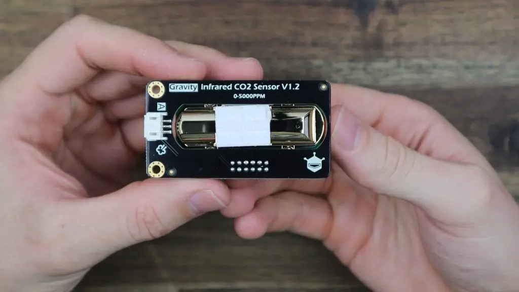
Our CO2 sensor uses infrared light to measure the concentration of CO2 within the air and then produces a 0-2V analogue signal.
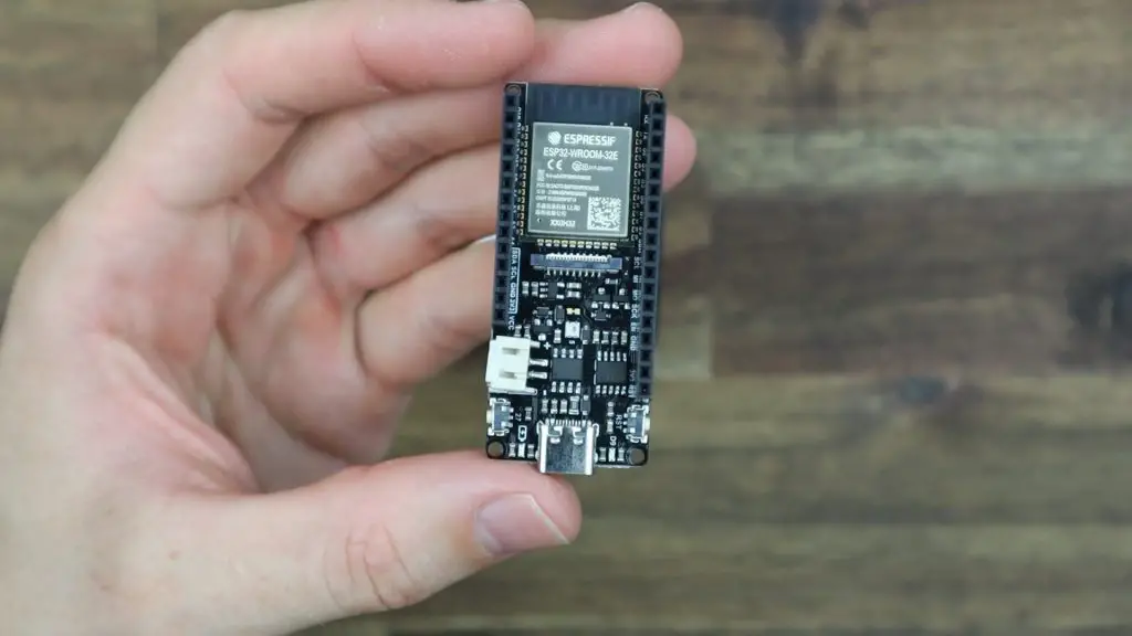
We’re going to read this signal using an ESP32 based microcontroller by DFRobot called a Firebeetle board. I’ve used one of these boards previously for my weather station because they have a great range of IO, integrated WiFi and Bluetooth connectivity and they’re designed to be power efficient. They even include a battery charging circuit and a JST connector plug for a lithium-ion or lithium-polymer battery.
I’m going to be using the board’s WiFi connectivity to send the measured data to Prometheus, which is an online time-series database, and I’ll then be creating a dashboard to view the data using Grafana. This dashboard will be able to be accessed on any internet-connected device with a browser and will allow time-based trends of the data to be created. I also want to include some local indication on the device so I’m going to be doing that with an I2C OLED display.
Finally, since I’ve already got a microcontroller and display, it would be good to measure some other environment metrics as well, so I’m going to also include a BME280 temperature, pressure and humidity sensor.
Watch my video of the build here, or read on for the full write-up:
What you Need For This Project
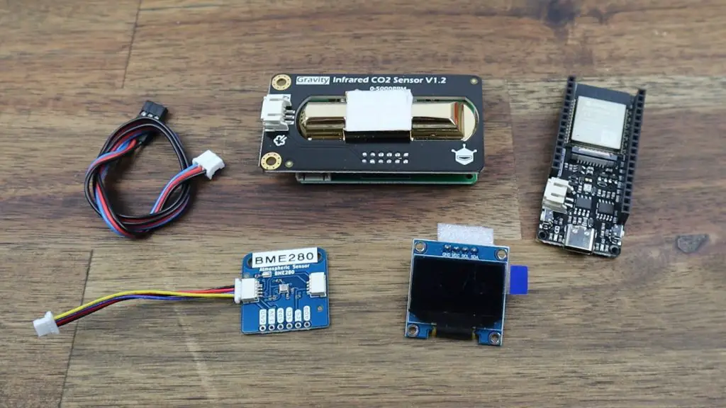
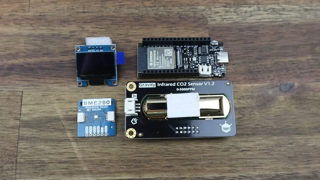
To complete this project, you’ll need the following main components in addition to basic wiring, header pins etc.:
- Firebeetle ESP32-E Microcontroller – Buy Here
- Gravity: Analog Infrared CO2 Sensor – Buy Here
- BME280 Environment Sensor – Buy Here
- I2C OLED Display – Buy Here
- Set of Various Screws – Buy Here
- M3 Brass Inserts – Buy Here
- 2mm Clear Acrylic – Buy Here
Designing And 3D Printing The Housing
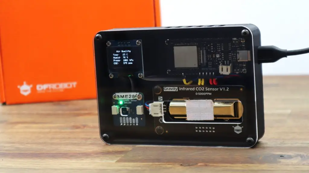
My goal is to build all of the components into a single desktop or wall-mountable device that I can power using a USB outlet and move around the house if I want to.
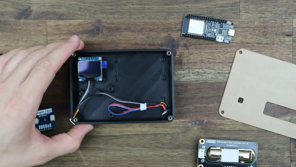
I quite like the futuristic look of the CO2 sensor, so I’m going to make the front cover of the housing clear so that we can see into it, and see the microcontroller, display and sensors. So for this reason it would be good to mount the four boards in a flat, rectangular layout as shown below.
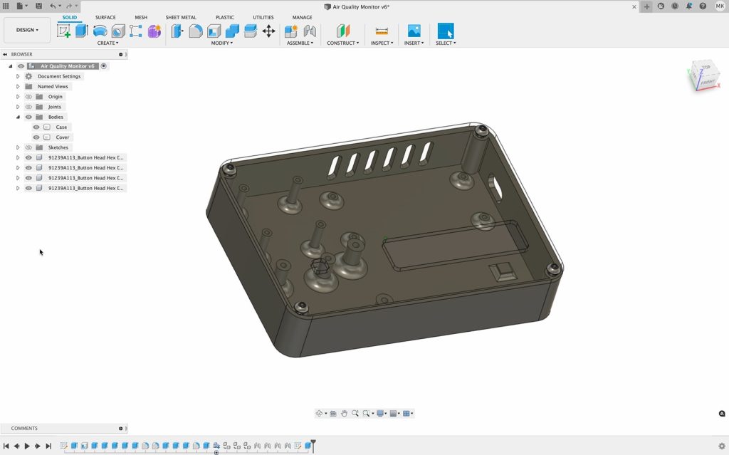
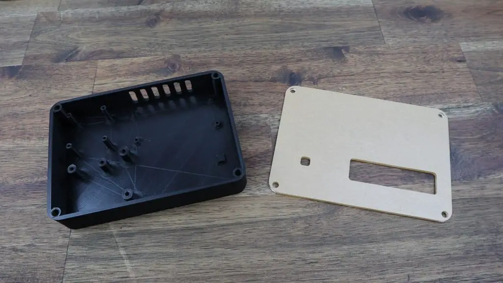
I designed the case in Fusion360, using a simple layout with 3D printed standoffs to mount each of the four components.
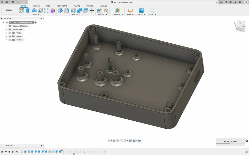
I then added a screw on a clear acrylic cover to the front. I also added some ventilation holes along the top and a cutout for the USB cable on the side.
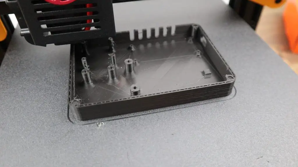
I 3D printed the case in black PLA. It’s just a single print and I didn’t need to add any supports as the cutouts are relatively small and are rounded at the corners. This depends on your printer’s abilities but I think most printers would cope with these small overhangs without requiring any print supports.
I laser cut the front cover from 2mm clear acrylic.
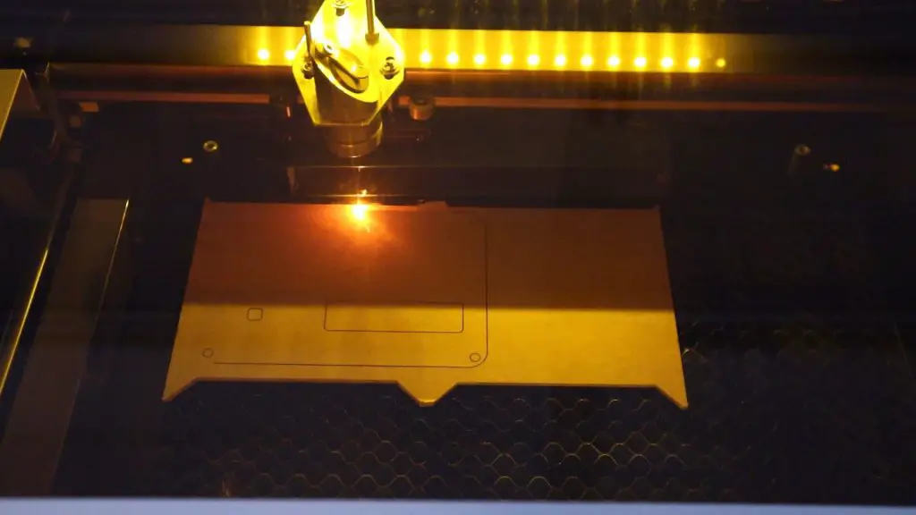
The front cover is a basic rectangular shape with the same profile as the housing and I’ve added a cutout for the CO2 sensor and one for the BME280 sensor so that they’re both exposed to the outside air.
Making Up A Wiring Harness
Before I install all of the components into the case, I’m going to make up a wiring harness to connect them together. The display and BME280 sensor both use the I2C interface to send and receive data and the CO2 sensor just needs a power supply and a connection to one of the analogue inputs.
Here is a basic wiring diagram for the connections:
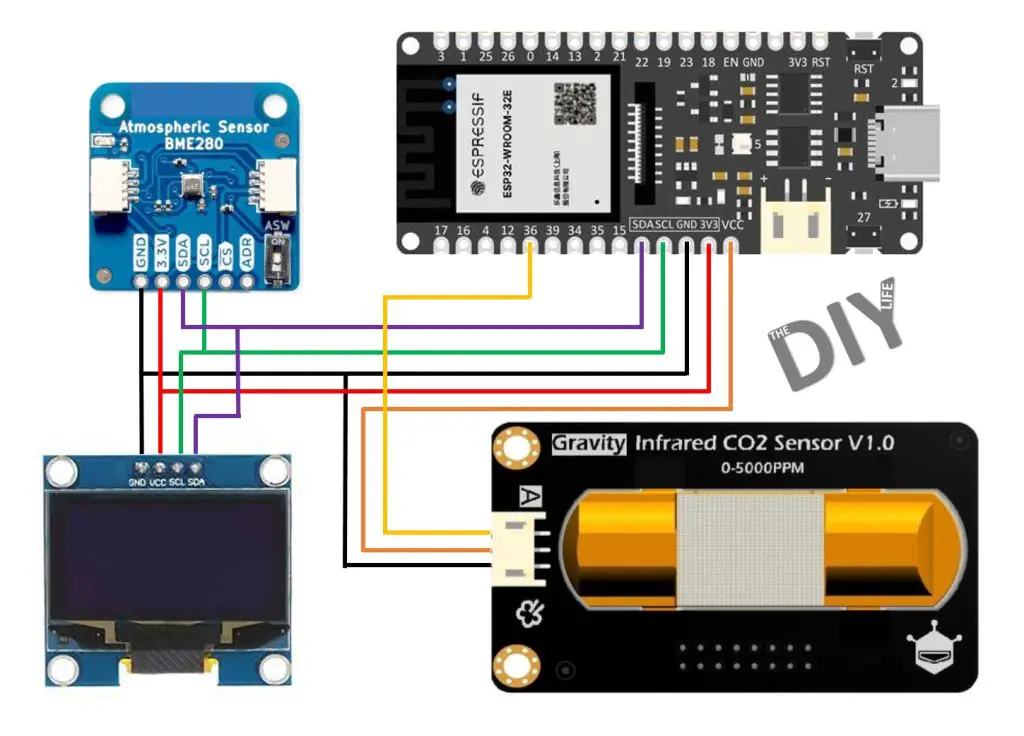
I initially used analogue input A4, shown in the subsequent photos, but I moved this to A0 as A4 doesn’t work when using WiFi on the Firebeetle board.
One important note is that the CO2 sensor requires a 5V supply. Its analogue output is compatible with 3.3V microcontrollers as it doesn’t go above 2.0V, but it still requires 5V to power it. For this reason, I’m going to be powering the sensor with 5V directly from the USB supply, while the display and BME280 sensor will be powered using 3.3V from the Firebeetle’s onboard regulator.
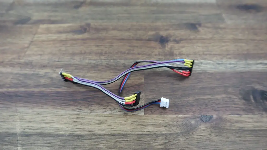
I made the wiring harness up using coloured ribbon cable as well as male and female header pins and I added some coloured heat shrink over the soldered connections.
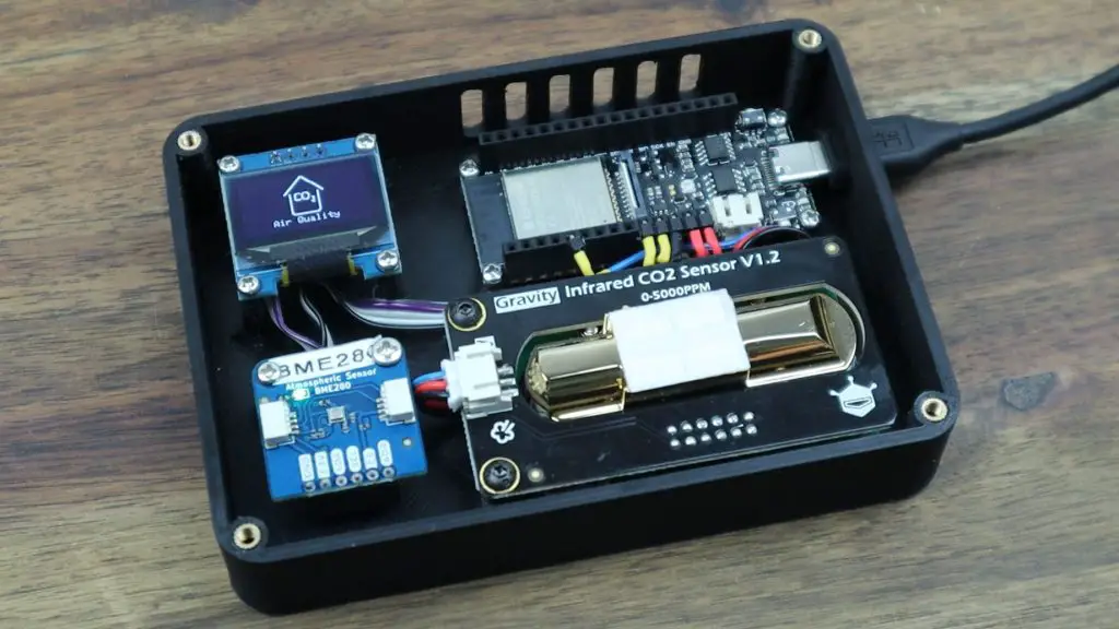
Installing The Components In The Case
With the standoffs already 3D printed on the housing, it’s relatively simple to install all of the components in the case.
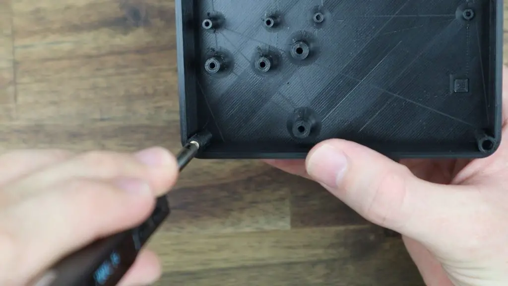
I’m going to start by using some M3 brass inserts to make the M3 screws that hold the lid in place a bit more durable. These are just melted into place in the printed pockets using a soldering iron which I’ve set to 200 degrees – which is about the same temperature as the PLA filament is printed at.
I’ll use a range of small screws to hold the boards in place, mostly M2.5 x 6mm screws, with the wiring running below the boards as far as possible. Make sure that you plug your connectors onto the correct pins and that they’re the right way around or your might damage your boards when you supply power to them.
With that all done, we can now close up the case using four M3x8mm button head screws and move on to programing our Firebeetle board.
Programming The Firebeetle ESP32-E Board
I’ve written up an Arduino sketch that takes readings from each of the sensors every minute and then updates the display and uploads the data to Prometheus.
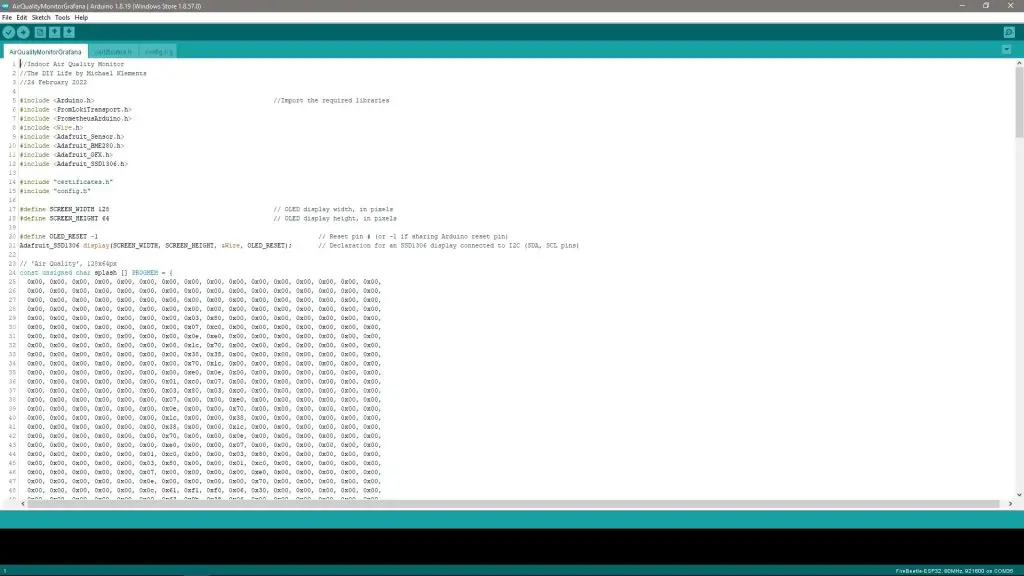
You can download the code from my Indoor Air Quality Monitor Github repository.
The posting to Prometheus part of the code is largely based on the example provided on the Grafana Cloud information page, which is linked to a GitHub repository called IoT with Arduino and Grafana.
There is a bit of setup involved in the code as you’ll need to set up your WiFi details as well as your Prometheus configuration information. The IoT with Arduino and Grafana repository explains this all in detail with screenshots, so head over to their repository if you need some additional help. Essentially, you need to update the config.h file to include your WiFi network name and password as well as your Grafana Cloud Remote Write Endpoint address, your Username and your API Key.
Once that is all done, you can upload the sketch and you should then start seeing some information being displayed on the OLED display and on your serial monitor.
Using The Indoor Air Quality Monitor
The CO2 sensor needs around 3-5 minutes to pre-heat, during which time it’ll give a reading of about 0.2V and it’ll then start producing a voltage between 0.4V and 2.0V, which corresponds to a CO2 concentration of 0-5000ppm.
I’ve set up the code to recognize these voltages and to indicate that the CO2 sensor is preheating before a reading is displayed.

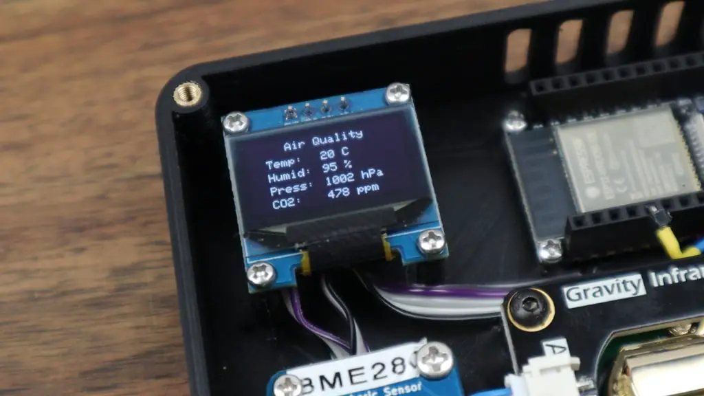
While preheating, we can still see that we’ve got readings from our BME280 sensor for the environment temperature, pressure and humidity.
After about 3 minutes, the CO2 concentration has now shown up on the display.
I’ve created a Grafana dashboard with an instantaneous gauge for each of the four metrics along the top and then a time-based trend below them.
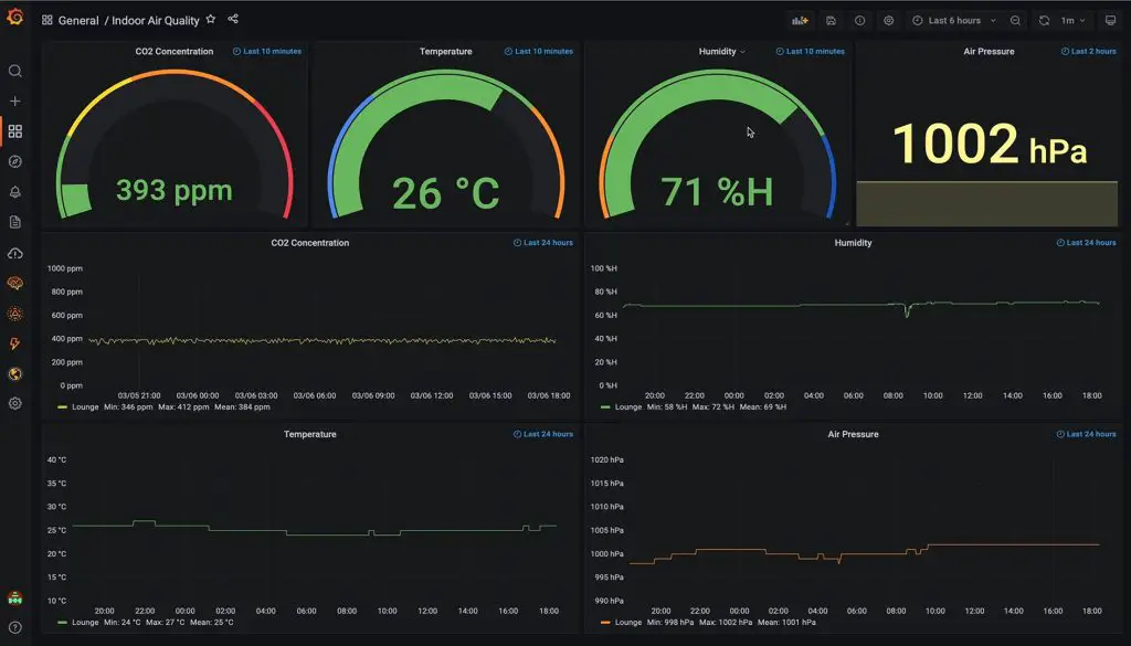
The CO2 sensor hasn’t really picked up many spikes in CO2 concentration but it is currently being used in a fairly large living space and we tend to keep some windows or doors open during the day for fresh air.
You can read up a bit more on creating dashboards and visualisations in Grafana from my full Grafana tutorial.
So we’ve now got a portable indoor air quality monitor that we can leave in any room to monitor the air quality and we can access remote logs and trends of the data through any internet-connected browser.
Let me know what you think of my Air Quality Monitor in the comments section and let me know if there is anything you’d add to it or change.
Pretty nice and as always beautiful designed. I like the looks of 3D prints and clear acrylic like my Pi server i have ordered from you.
but the cool part from this project is the prometheus and grafana stuff.. i would like to host all that by myself on the previous mentioned Raspberry Pi in his beautiful case 😉 but i struggle with the software part… and the tutorials on github are all for the cloud variant… it would be super nice if you can make a tutorial on how to self host the prometheus and grafana stuff.
Hi Sepia,
Thanks for the great feedback and the suggestion. I’ll have a look at putting together a locally hosted tutorial. From my experience, it’s probably easier to go local with InfluxDB and Grafana. InfluxDB have pretty good documentation on installing it on a Raspberry Pi.
Hi oh super thank you then i will have a look at that ? and yeah would be great if you do a tutorial ?
What is the exact model of laser cutter that you use in your videos? The K40 link on amazon doesn’t appear to be the same model
The one I have is three years old from an eBay supplier, so they’re no longer available.
what is it
Hi,
Great project. Been looking for years how to do a DIY CO2 monitor but always been limited by my lack of coding knowledge. Not being a coding guru, what would it take to make this work with Blynk instead of Prometheus or Grafana? Would you be able to provide such code for it to work with Blynk?
Thank you very much in advance.
Regards
Hi were you able to get the blynk code ?
hey, im new to arduino and i would like to ask if it’s possible to use Multi-function Environmental Module – ENS160+BME280 instead of BME280 Environmental Sensor?
Thank you
Great work! Just the springboard project I’ve been looking for. I think in an effort to keep costs down, I’ll be using an SCD40 instead though. And I’m thinking a PM2.5 might be a nice bonus.