Easily pick colours from physical objects with this Arduino based RGB colour picker, enabling you to recreate the colours you see in real life objects on your pc or mobile phone. Simply push a button to scan the colour of the object and you’re given the RGB colour values as well as an indication of the measured colour on an RGB LED.
I’ve designed a simple 3D printed enclosure for the electronics to make the device portable, simply plug it into a USB port, charger or power bank to power it up.
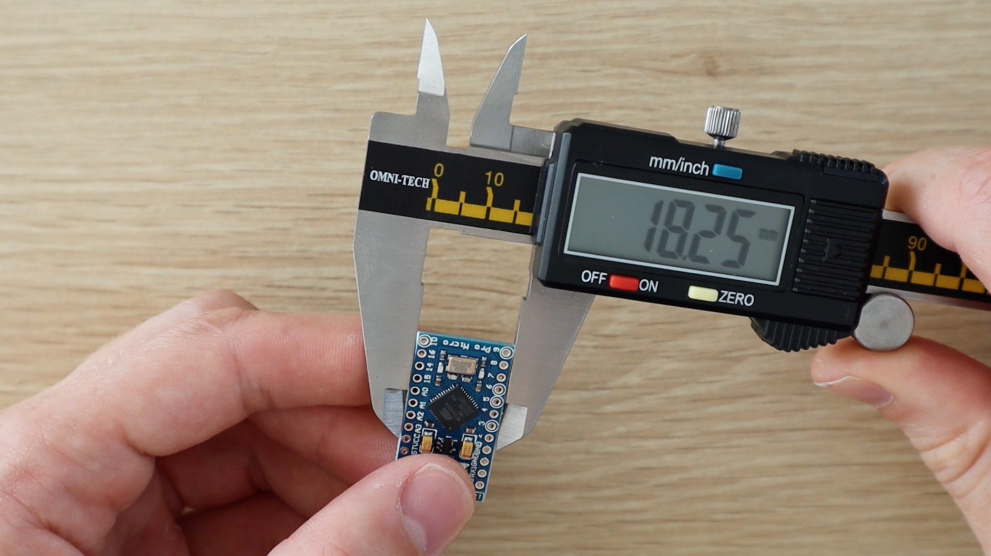
I usually try to use an Arduino Uno as this is one of the most widely used Arduino boards, but to make this device portable, it has been designed around an Arduino Pro Micro board. It can however be easily adapted to run on most of the other Arduino compatible boards with enough IO, such as the Uno, Leonardo or Mega, you’ll just need to build it into a larger enclosure.
This guide assumes that you’ve worked with an Arduino micro-controller before know the basics of programming the Arduino and connecting an LCD panel to it. If you do not, follow the linked guides for more information and in-depth explanations.
Here is a summary video of the build, otherwise read on for the full guide to make your own.
What You Need To Build Your Own Arduino RGB Colour Picker
- Arduino Pro Micro (Or Other) – Buy Here
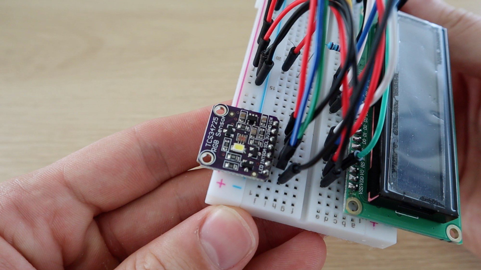
- TCS34725 RGB Sensor – Buy Here
- 16 x 2 LCD Panel – Buy Here
- Push-button – Buy Here
- 2 x 10K Resistors – Buy Here
- 3 x 220Ω Resistors – Buy Here
- 470Ω Resistor – Buy Here
- RGB LED – Buy Here
- 7 Pin Female Header Strip (Cut to Length) – Buy Here
- 10K Potentiometer – Buy Here
- Breadboard & Jumpers for Testing – Buy Here
- 3D Printer & White/Black Filament (Optional for Housing) – This One Used
In addition to these, you’ll need basic tools for working with electronics, including a soldering iron if you’re permanently building your circuit for use in an enclosure as well as a PC for programming your Arduino.
Connecting the RGB Colour Picker Test Circuit
It’s always a good idea to assemble your components onto a breadboard first to test them and make sure that your circuit and software are working correctly before making any soldered connections.
The components are connected onto the breadboard as shown below:
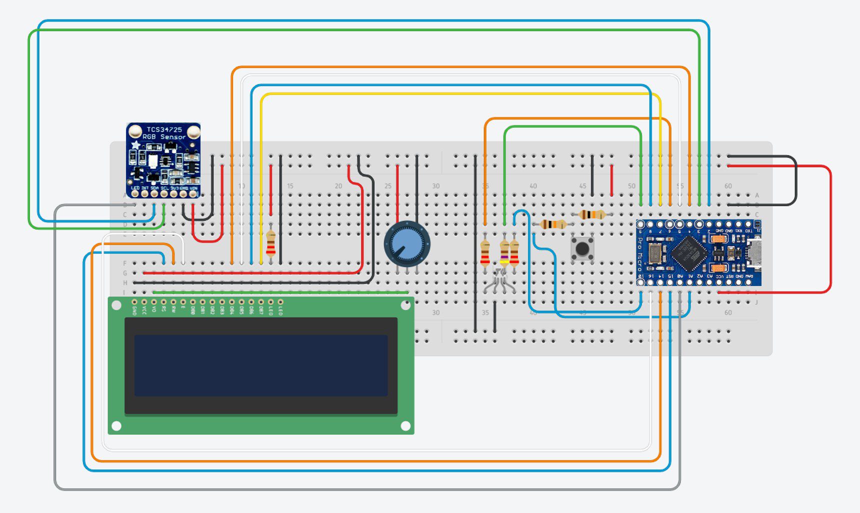
There is nothing particularly unique or strange in any of these connections between the components and the Arduino, they are typical basic circuit configurations for connecting the LCD, push button and LEDs to the Arduino.
The 10K resistors are used for the push button connection and the 220Ω resistors for the colour sensor LED and the red and blue legs of the RGB LED. The 470Ω resistor is used for the green leg of the LED to reduce its brightness a little to create more realistic looking colours.
The 10K potentiometer is connected to control the contrast of the LCD display, if you are not getting any characters displayed on your LCD and no errors uploading your program, first try adjusting this potentiometer. You may find that the characters are actually being displayed, they’re just too dim to see.
The RGB colour sensor is connected to the Arduino using a simple I2C interface. Make sure that you’re using the correct pins on your Arduino for this interface if you’re using a different board.
If you are using a different Arduino board, make sure that you have the same functionality on each pin used on the Pro Micro. For example, you need PWM enabled pins for the control of the RGB LED in order to simulate the picked RGB colour.
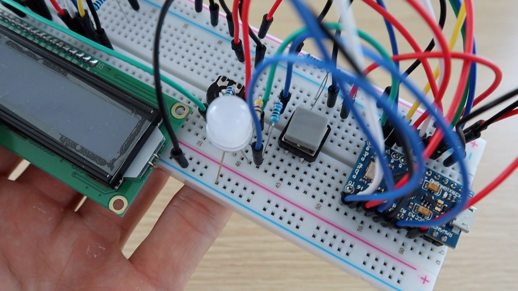
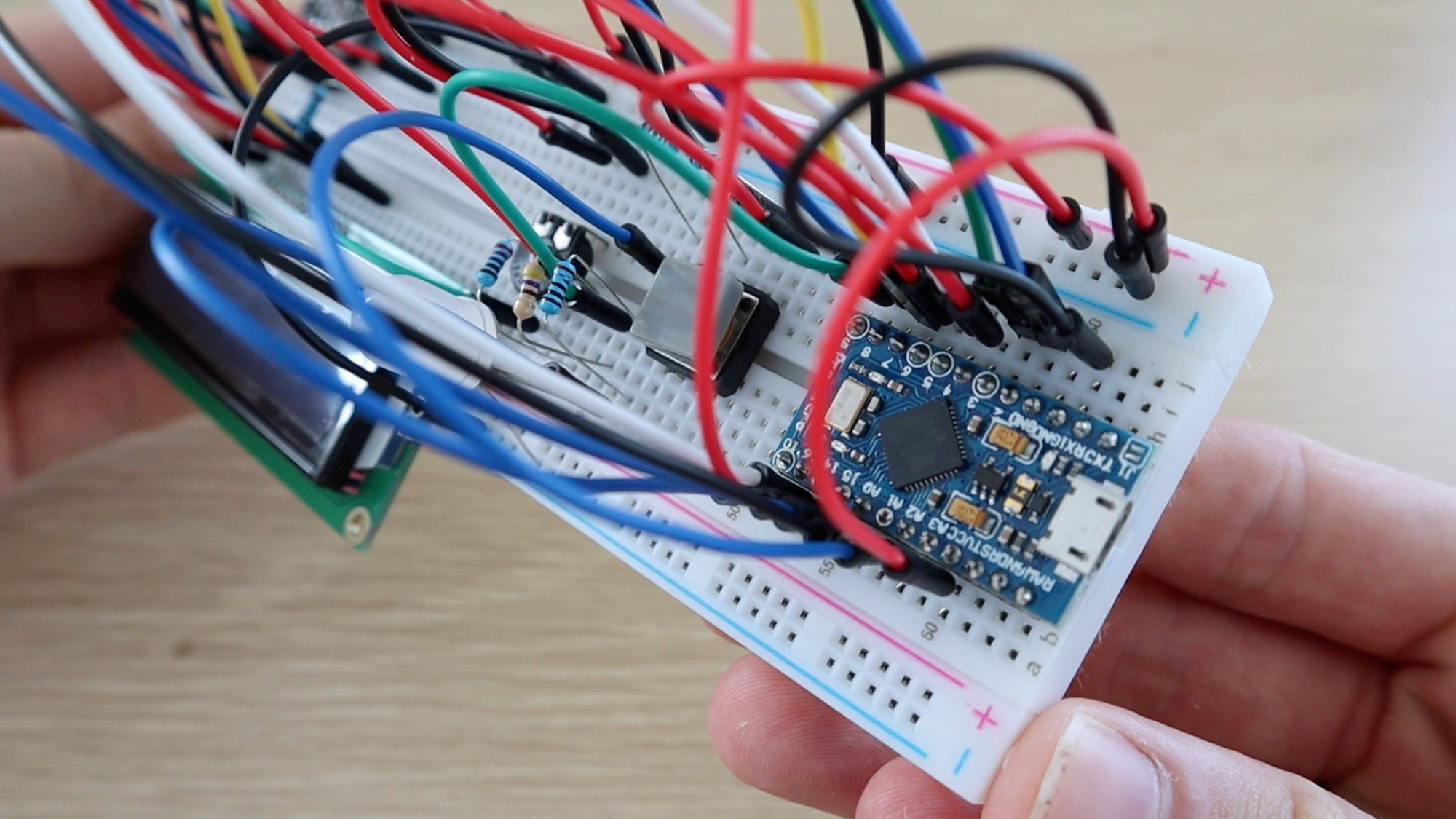
Here are some pictures from the assembly of the components onto the breadboard:


And the final completed breadboard:
Programming Your Arduino RGB Colour Picker
Now that you’ve assembled your components onto the breadboard and made the required interconnections, you can load the code onto your Arduino and check that the components work correctly.
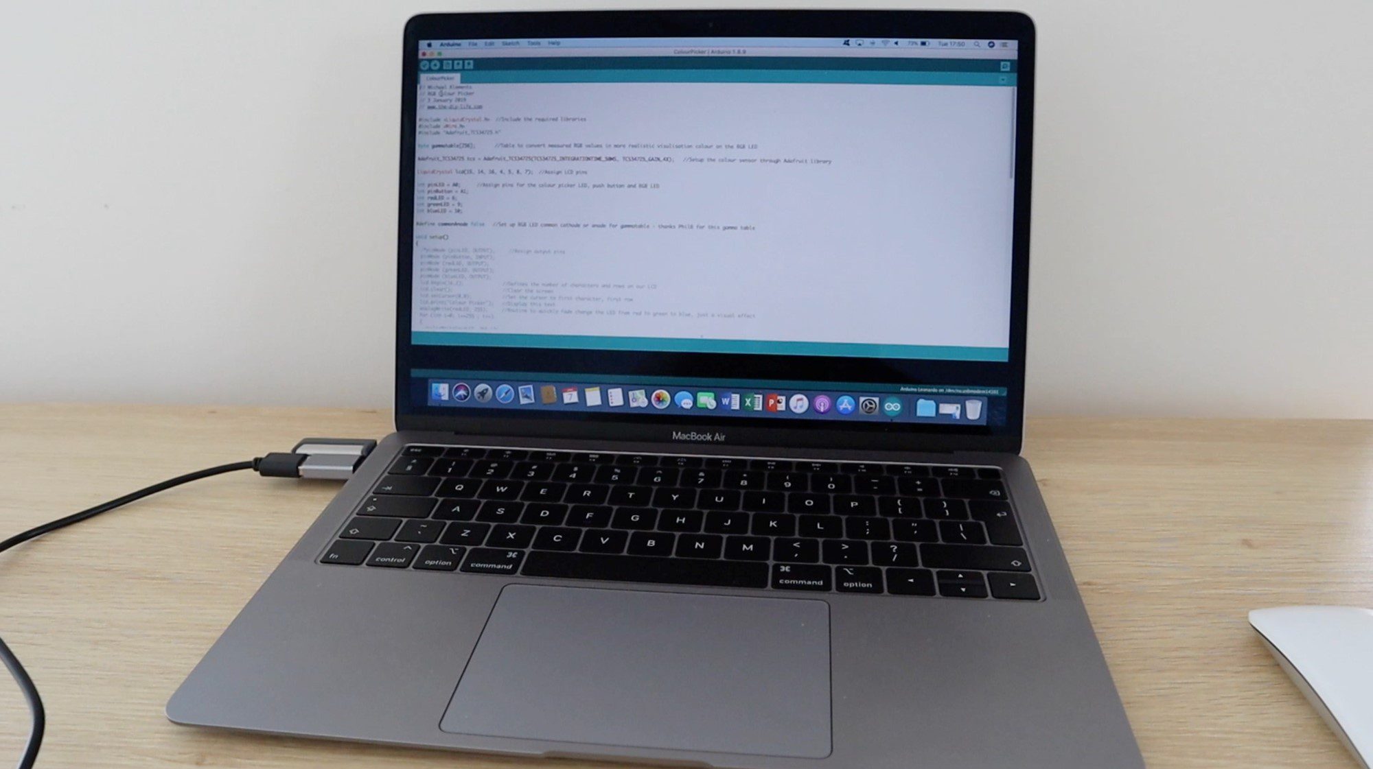
Before plugging the USB cable into your Arduino, check all of your connections again to make sure that they are correct. The USB cable supplies power to the board and connected components which may damage them if not connected correctly.
This particular board, the Arduino Pro Micro acts as a Leonardo board when connected to your PC, so make sure to select the correct board type in the Arduino IDE.
Here is the code:
// Michael Klements
// RGB Colour Picker
// 3 January 2019
// www.the-diy-life.com

#include <LiquidCrystal.h>  //Include the required libraries
#include <Wire.h>
#include "Adafruit_TCS34725.h"

byte gammatable[256];       //Table to convert measured RGB values in more realistic visulisation colour on the RGB LED

Adafruit_TCS34725 tcs = Adafruit_TCS34725(TCS34725_INTEGRATIONTIME_50MS, TCS34725_GAIN_4X);   //Setup the colour sensor through Adafruit library

LiquidCrystal lcd(15, 14, 16, 4, 5, 8, 7);  //Assign LCD pins

int pinLED = A0;      //Assign pins for the colour picker LED, push button and RGB LED
int pinButton = A1;
int redLED = 6;
int greenLED = 9;
int blueLED = 10;

#define commonAnode false   //Set up RGB LED common cathode or anode for gammatable - thanks PhilB for this gamma table

void setup()
{
  pinMode (pinLED, OUTPUT);     //Assign output pins
  pinMode (pinButton, INPUT);
  pinMode (redLED, OUTPUT);
  pinMode (greenLED, OUTPUT);
  pinMode (blueLED, OUTPUT);
  lcd.begin(16,2);              //Defines the number of characters and rows on our LCD
  lcd.clear();                  //Clear the screen
  lcd.setCursor(0,0);           //Set the cursor to first character, first row
  lcd.print("Colour Picker");   //Display this text
  analogWrite(redLED, 255);     //Routine to quickly fade change the LED from red to green to blue, just a visual effect
  for (int i=0; i<=255 ; i++)
  {
    analogWrite(redLED, 255-i);
    analogWrite(greenLED, i);
    delay(3);
  }
  for (int i=0; i<=255 ; i++)
  {
    analogWrite(greenLED, 255-i);
    analogWrite(blueLED, i);
    delay(3);
  }
  analogWrite(blueLED, 0);
  lcd.setCursor(0,1);
  if (tcs.begin())          //Connect to the colour sensor
  {
    lcd.print("Ready");
  }
  else
  {
    lcd.print("Sensor Error");
    while (1);
  }
  digitalWrite(pinLED, LOW);  //Turn off the sensor's white LED
  for (int i=0; i<256; i++) //Set up the gamma table for RGB conversion
  {
    float x = i;
    x /= 255;
    x = pow(x, 2.5);
    x *= 255;
    if (commonAnode)
    {
      gammatable[i] = 255 - x;
    }
    else
    {
      gammatable[i] = x;
    }
  }
}

void loop()
{
  if (digitalRead(pinButton) == LOW)  //If the button is pressed
  {
    float red, green, blue;       //Create variables for the measured RGB values
    digitalWrite(pinLED, HIGH);   //Turn the sensor LED on for measurement
    delay(500);                   //Delay to allow any movement from the button press to stop
    tcs.setInterrupt(false);      //Start measurement
    delay(60);                    //Takes 50ms to read
    tcs.getRGB(&red, &green, &blue);  //Get the required RGB values
    tcs.setInterrupt(true);
    delay(500);                   //This delay and delay at end just allow time for the button to be released, avoids repeated readings
    digitalWrite(pinLED, LOW);    //Turn off the sensor LED
    lcd.clear();                  //Clear the LCD display
    lcd.print("Colour Picked");   //Display the results
    lcd.setCursor(0,1);
    lcd.print("R:");
    lcd.print(int(red));
    lcd.print(" G:");
    lcd.print(int(green));
    lcd.print(" B:");
    lcd.print(int(blue));
    analogWrite(redLED, gammatable[(int)red]);      //Set the RGB LED to reflect the measured colour with gammatable conversion
    analogWrite(greenLED, gammatable[(int)green]);
    analogWrite(blueLED, gammatable[(int)blue]);
    delay(500);
  }
}
Download – RGB Colour Picker Code
The code contains comments to guide you through each line and what its purpose is. The colour identification and LED portion is based on the Adafruit colorview example code.
You will need to have the Adafruit libraries installed. This is easily done by clicking on Tools -> Manage Libraries in your IDE and then typing in “Adafruit TCS” in the search bar and installing the found library.
Some things to look out for in the code:
The LCD assigned pins are in a weird order (15 ,14 ,16 ,4 ,5 ,8 ,7). I usually try and keep the pins sequential but in this example they’re a bit mixed up for two reasons, one because I needed to work around the available PWM pins for the LED and the second because the pins on the Pro Micro are not all in sequential order.
The colour sensor LED (pinLED) and push-button (pinButton) are connected to the Pro Micro’s analogue inputs, being used as digital IO, as there were not enough digital IO pins available.
There is a brief routine to fade the LED between red, green and blue when starting up. This is just a visual effect and can be removed if you’d like your colour picker to start up quicker. It takes about 1.5 seconds to run through.
The program won’t progress past the setup if it does not establish a connection with the colour sensor, this will show up as “Sensor Error” on your LCD. If the LED is coming on, indicating power to the sensor then check your SDA and SCL connections.
The gamma table simply converts the measured RGB values from the sensor into values which will result in a more realistic LED representation of the actual colour, this is just to improve the LED visualisation effect and doesn’t have an affect on the measured RGB values displayed.
The code then waits for the push-button input to take a reading from then sensor and display the values on the LCD and through the LED. The three delays in the loop if statement are simply to allow and movement from pushing the button to stop and then to avoid taking repeated readings before the button is released again as the actual reading and cycle time would be about 100ms. You can adjust these values for faster colour picking.
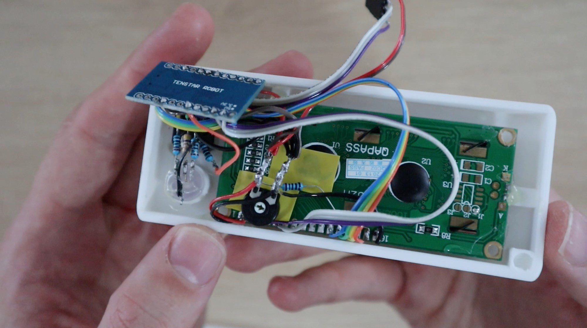
Installing the Components into the Housing
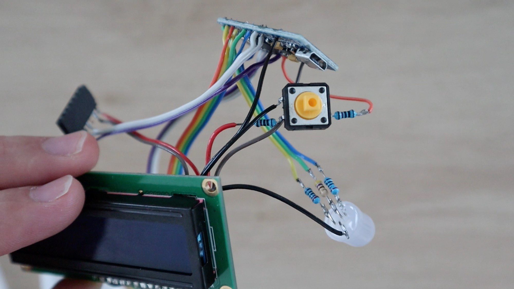
In order to make a useful and portable device, I decided to solder the components together and mount them into a housing.
A circuit of this complexity should probably be designed onto a PCB to make it easier to handle and more robust inside the enclosure, but most people don’t have access to PCB manufacturing services so I’ve stuck with soldering the components together with sections of ribbon cable.
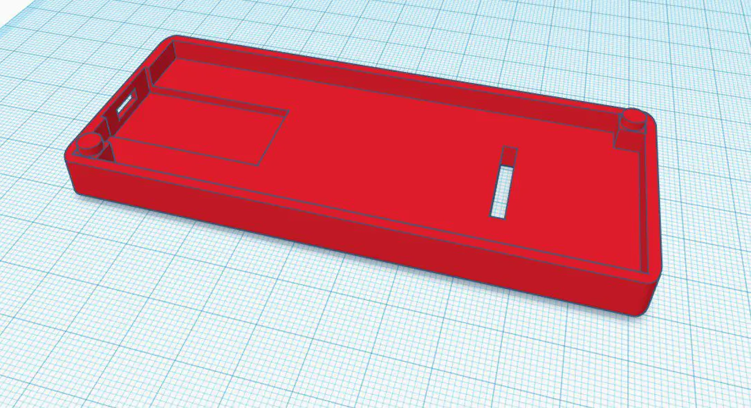
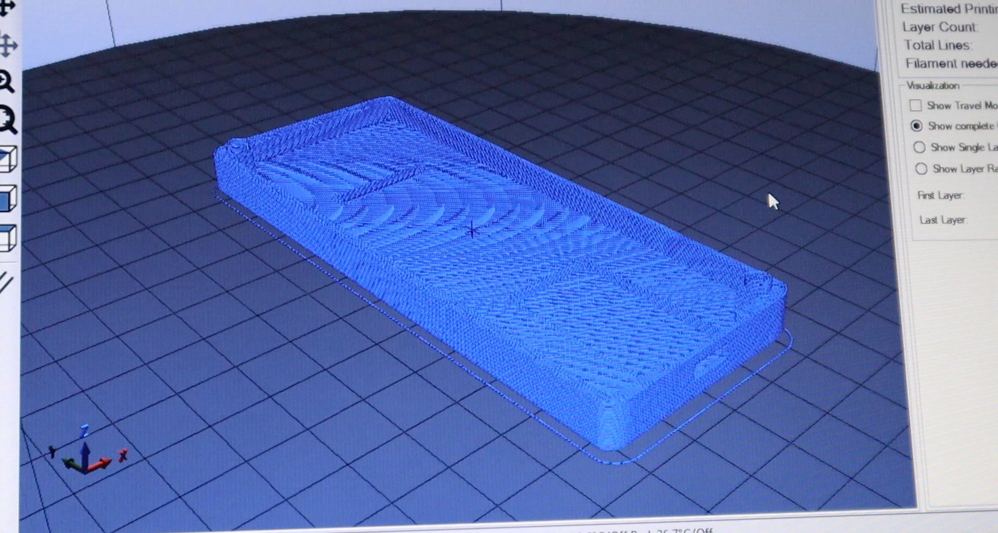
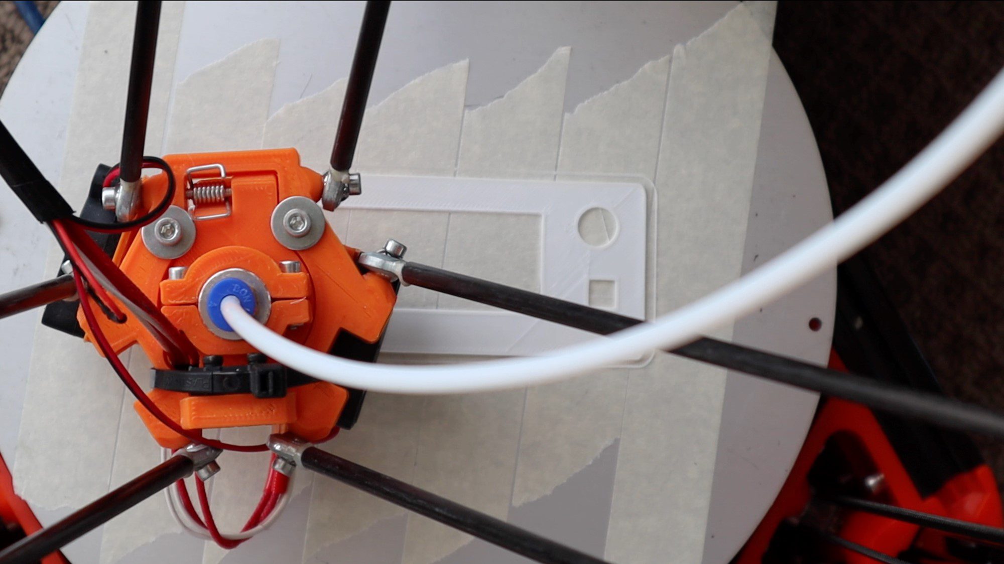
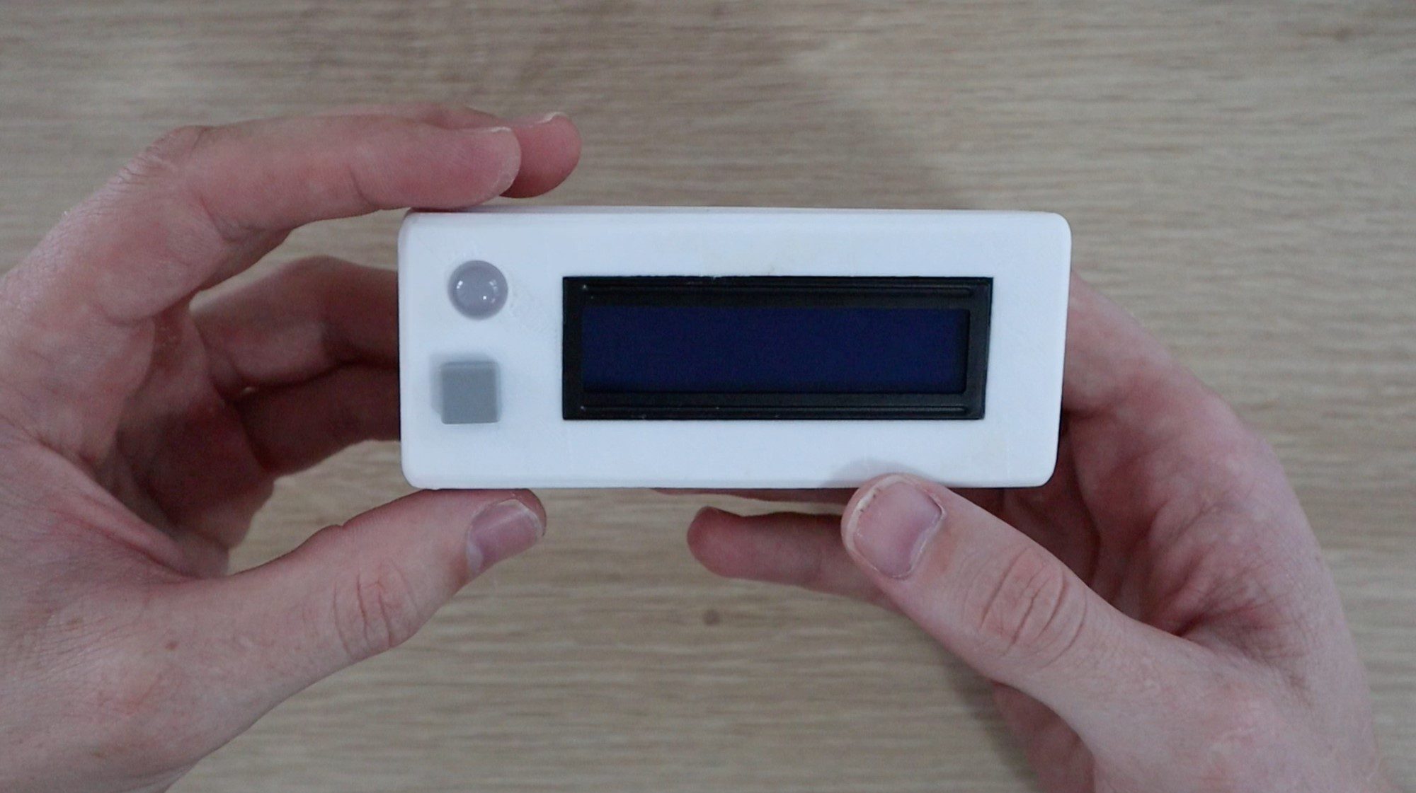
3D Print the Housing
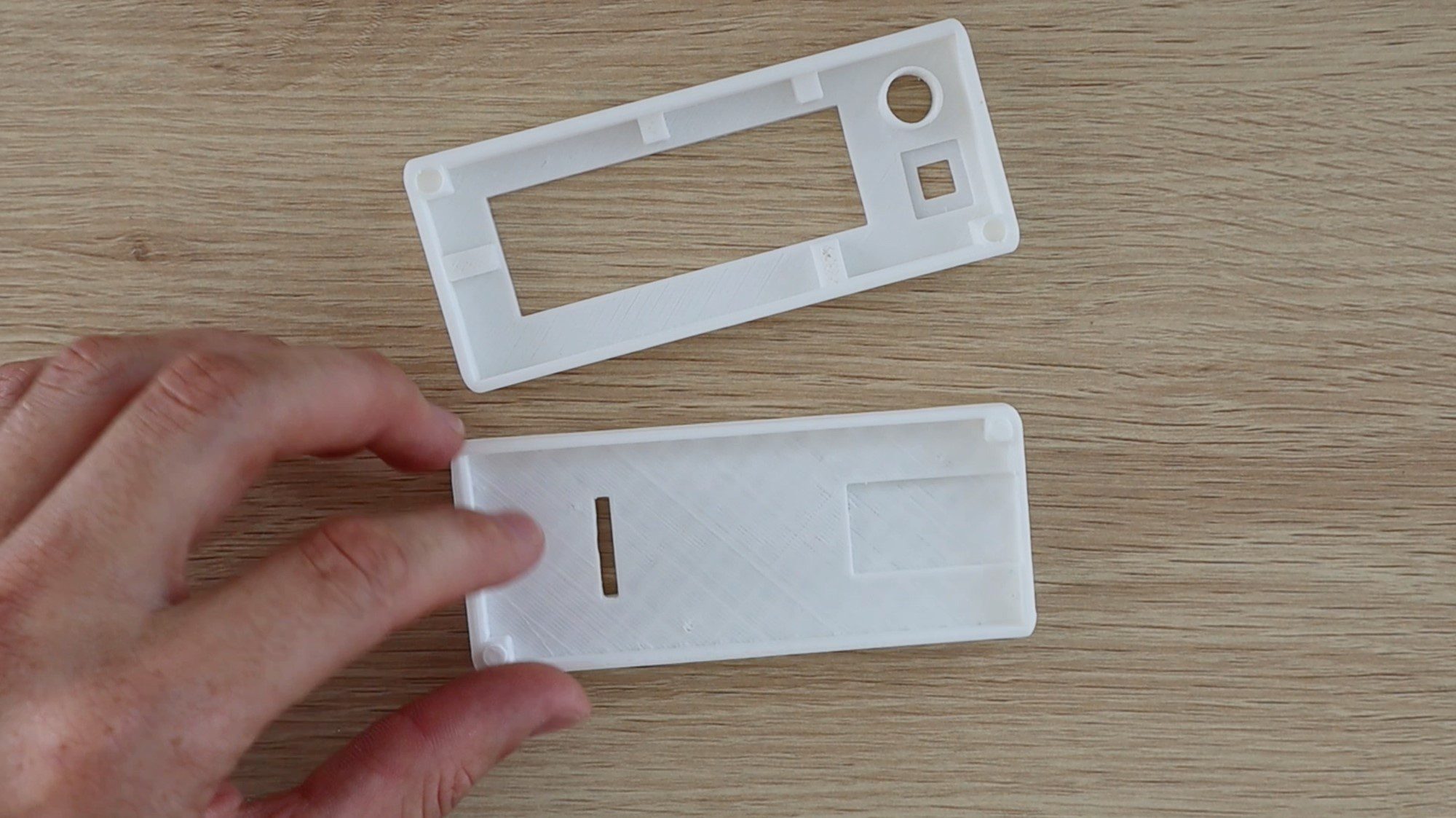
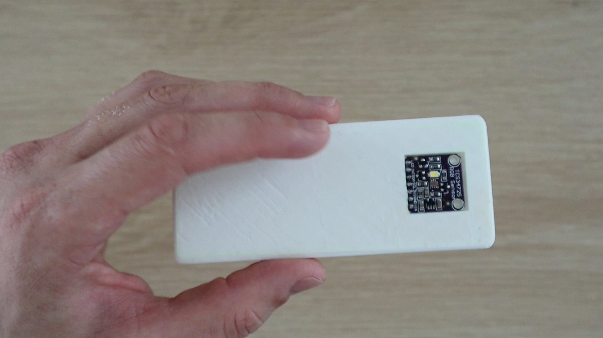
I designed a basic rectangular housing for the colour picker, the 3D print files can be downloaded through the link provided after the images.
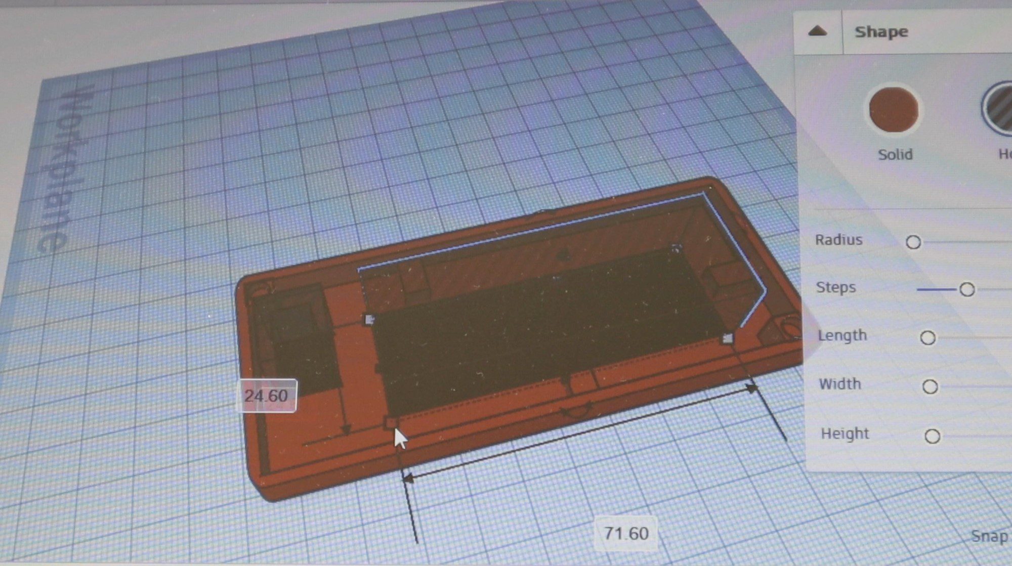
Download – Colour Picker Enclosure 3D Print Files
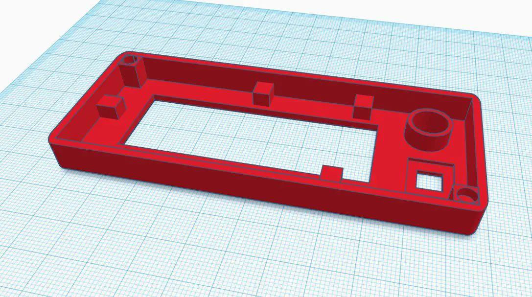
The colour sensor is on the back so that you can hold the device over an object and pick the colour with the readout shown on the front.
I printed the housing using white PLA and 20% infill, I would avoid using a coloured filament for the back panel as you don’t want to introduce reflected coloured light onto the surface being picked. Stick with either black or white.
The housing dimensions are approximately 110mm (4.3”) x 46mm (1.8”) x 20mm (0.78”) with both halves assembled. Each half is 10mm (0.39”) high.
Solder the Circuit
Once you’ve 3D printed the housing, you’ll have an idea of where all of the components are mounted and how long to make the interconnections.
Start by soldering each component to your Arduino as you remove it from the breadboard and try to only remove components to make up a full circuit at a time.
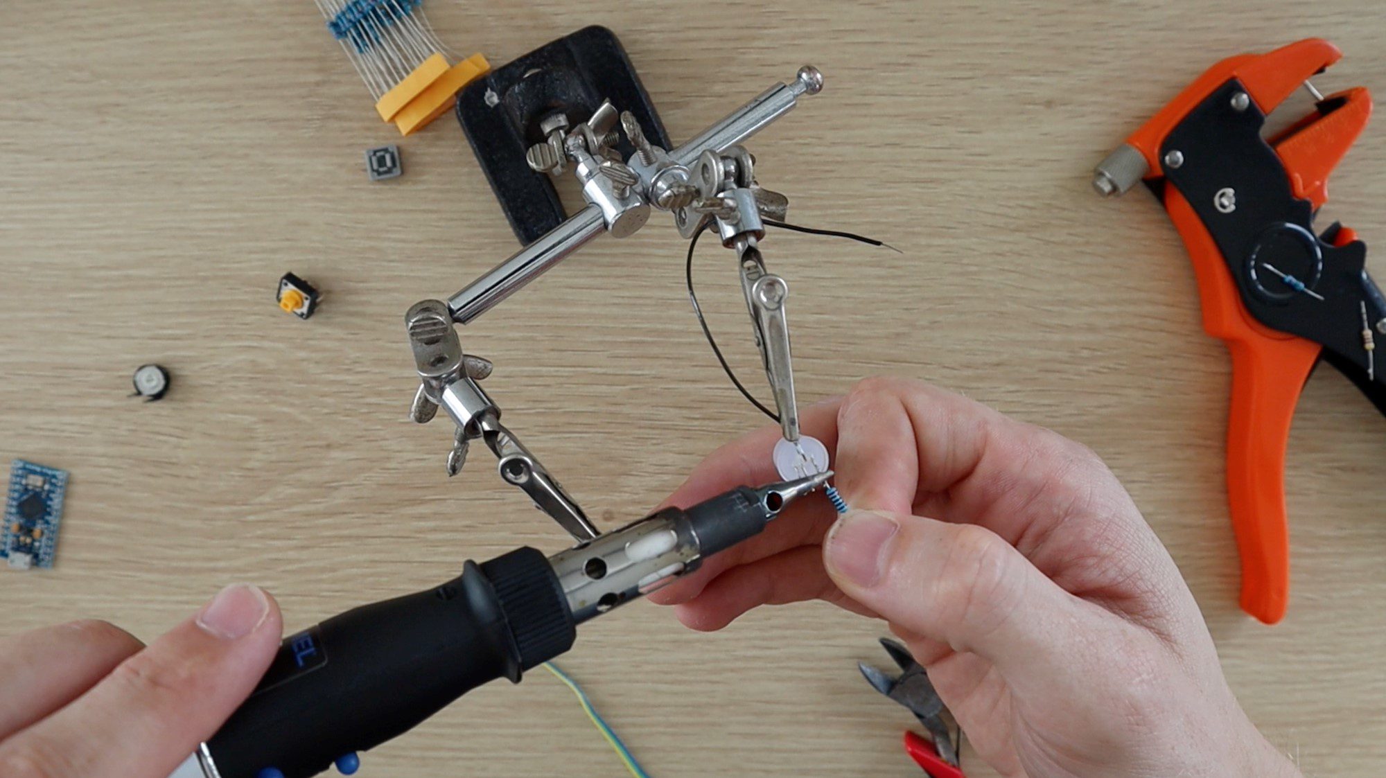
For example, start with the push-button circuit and solder the resistors to the push-button and then connect them to the Arduino before removing the LED components. This way you’ll be able to keep track of the components and make sure that you’re connecting them individually to the correct Arduino inputs and outputs.
Take care with the LCD panel and the colour sensor to make sure that you make the connections to the correct Arduino IO ports.
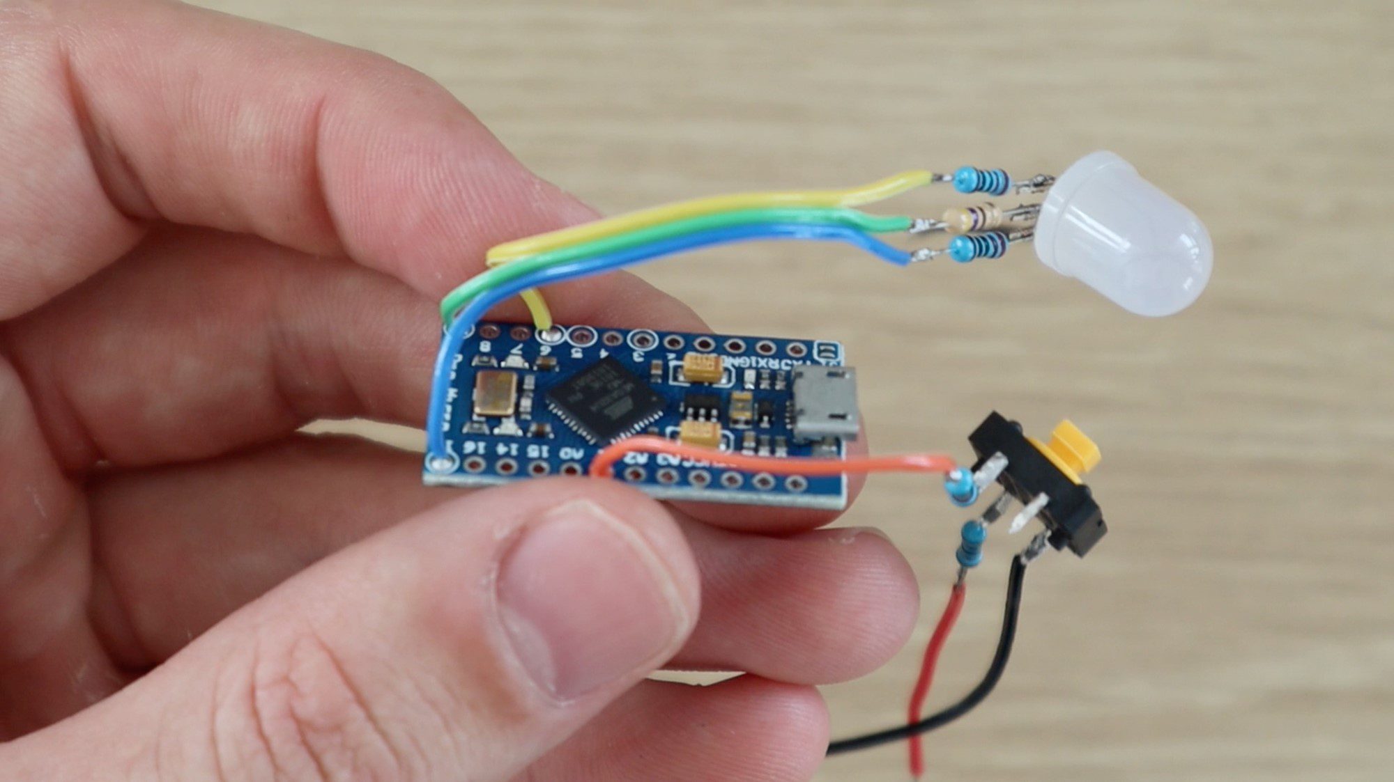
The colour sensor connections should be soldered onto the 7 pin female header strip (cut an 8 pin or longer header strip down to 7 pins) to enable it to be plugged in through the back section of the housing. This just enables the two halves to be properly separated if you need to. You can also solder directly to the colour sensor with a section of ribbon cable, just make sure that the ribbon cable runs through the slot in the housing before soldering the connections.
There are a number of connections to be made to GND and 5V and it makes things easier to connect them to larger central points rather than trying to solder them all onto the two Arduino pins. I connected them all onto the two outside legs of the LCD potentiometer as this is roughly in the centre of the housing and has the largest surface area to make the connections.
Once you’ve made all of your connections and you’re happy with the connection lengths. Try powering up your circuit again to verify that everything is working correctly before mounting the components into the housing. Be careful and ensure that none of the components or exposed terminals are touching each other, which may lead to a short circuit.
If your circuit is working correctly then you can mount your components into the 3D printed housing.
Mount Components into the Housing
The last step is to mount your components into your housing. I used a hot melt glue gun to mount the components, you can also use epoxy or small amount of superglue.
The colour sensor can be glued into the cavity on the back of the housing with the pin header strip sticking through to the inside of the housing. The female header strip will then be used for the sensor to plug into the circuit.
Mount the push-button, LCD and LED through the holes in the front panel and glue them into place on the inside of the housing. If your push-button has a press-on cap, install that piece as well.
Your Arduino should fit snuggly into the slot in the base and shouldn’t require any glue to hold it into place but if it does, make sure you don’t put glue on any components on the back of the board. Rather glue it in place along the edges.
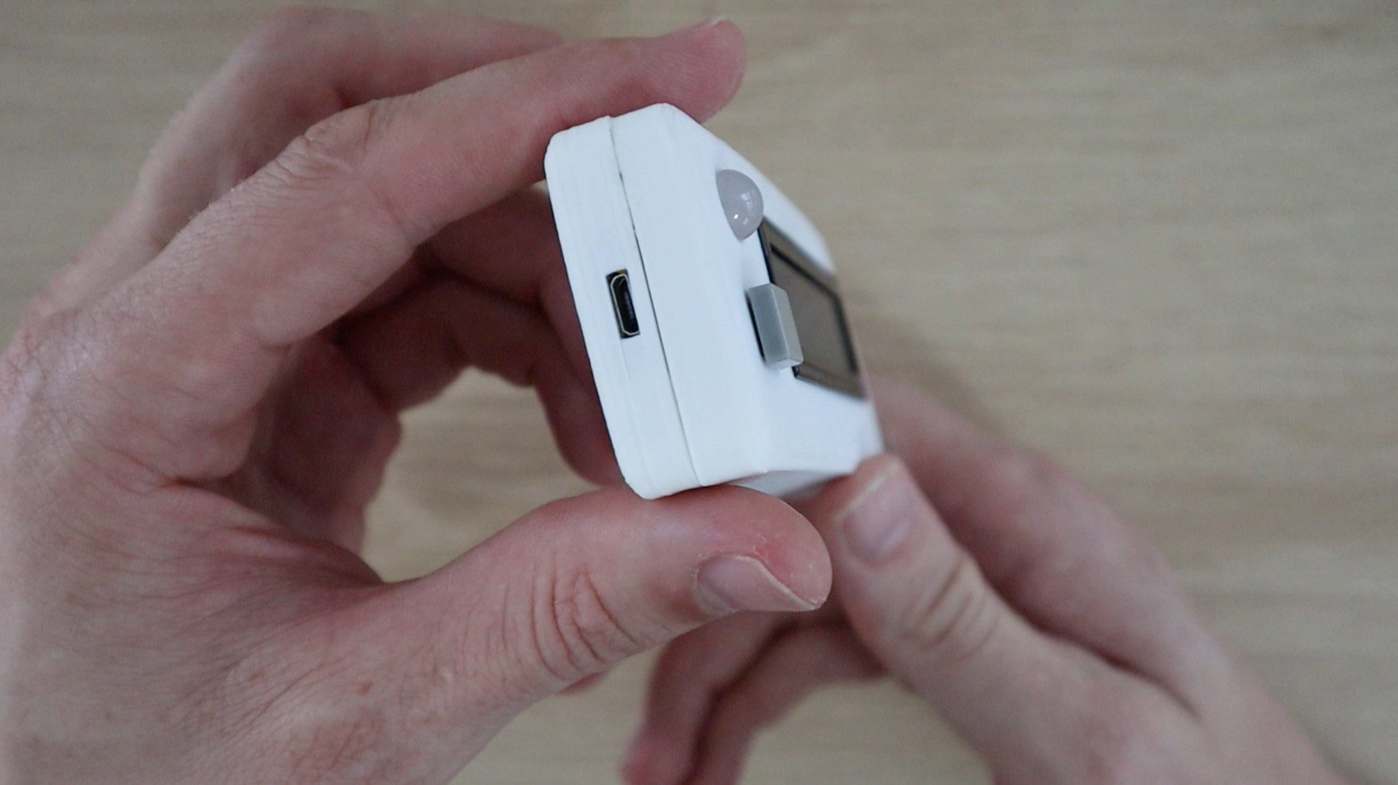
The micro USB port should now be easily accessible through the side of the housing.
Glue the two halves together, using the pegs on the two corners as a guide. These should press together tightly and assist in holding the two halves together. Make sure that none of your exposed terminals or leads on your resistors, LED or potentiometer are touching anything else in your circuit. If they are, use a bit of insulation tape or paper to separate them or cover them up to prevent short circuits.
Lastly, test your colour picker and make any final tweaks you’d like to the software.
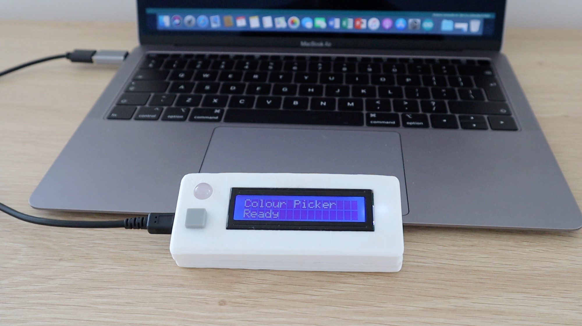
Using Your RGB Colour Picker
To use your colour picker, plug a micro USB cable into the port on the side of your colour picker and connect it to a powered USB port on a PC, charger or power bank to power it up.
The startup sequence should run and then you’ll be able to pick a colour.
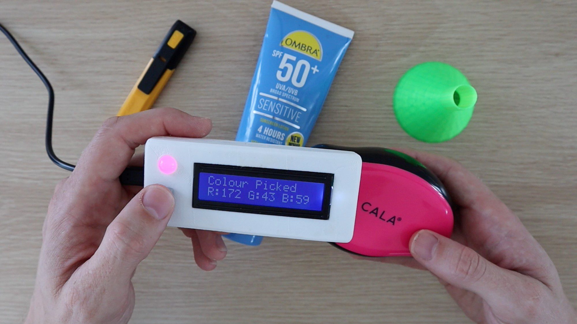
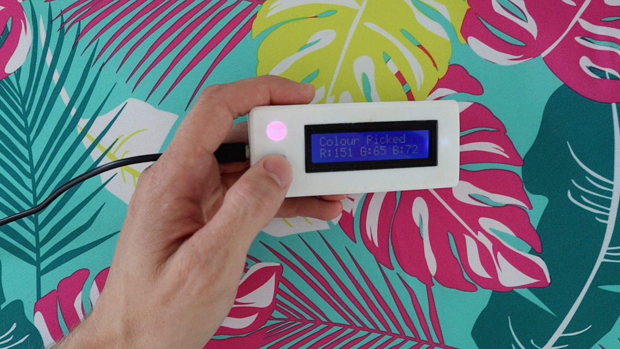
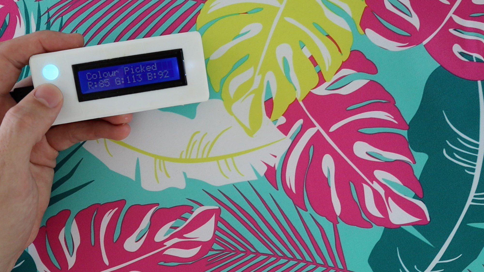
Place the sensor over the colour you’d like to pick and then push the button to pick the colour. The LED light on the sensor should come on momentarily, after which you’ll get an RGB readout on the LCD and the LED will change to reflect the colour which has been picked.
The coloured feedback LED is meant to give you an indication of the colour which has been identified. This is just a quick way for you to check that the sensor has picked up on the correct surface and is not always an accurate representation of the colour due to limitations with the way in which these LEDs work. For example, they can’t show blacks or greys as the actual LED diffuser material is white and can only produce light in order to create colours. For this same reason, darker colours also don’t show up well on the LED although the measured RGB values are correct.
Have your tried making your own RGB colour picker using an Arduino and the TCS34725 sensor module? Let us know how it went in the comments section below. We would love to hear your tips, tricks and any changes you’ve made to the design.
I have been very frustrated by your Colour-picker Instructable. The wiring diagram is the reversal of the pictures, and I have tried them both and get the very same response:
The LCD lights and shows the rectangular matrices on the top row only, and nor figures.
The RGB LED does not light at all and the button has no effect when pressed.
The TC34725 board lights the “picker” LED when plugged in.
I can’t imagine that you can solve my problem with these clues, but what else can I do?
Hi Bill,
Sorry you haven’t managed to get your colour picker to work, I’ll try to help you out as best I can. Just to get a feel for your level, have you worked with Arduinos and LCDs before?
I’m not really sure what you mean by the reversal of the pictures. Are you saying that you’re assembling directly and not on a breadboard, meaning the terminals are reversed?
To really understand the project and what is going wrong with yours, I would break the project up into smaller sections. Start by getting the LCD working and displaying your name for example. Have a look at our tutorial on connecting an LCD to an Arduino for more information on this.
Then try getting the RGB LED to light up with different colours.
Finally, connect the colour sensor and check on the Serial Monitor that you’re getting a good colour reading.
If you aren’t able to work through these, then go back to the individual component level and retrace all of your connections and make sure that they’re connected to the correct pins on the sensor, LCD and Arduino.
It’s difficult for me to tell you what to fix as there is a large number of things which could cause the problems you’re describing.
Briefly, the LCD problem you’ve got sounds like the data pins are muddled up. The light and fact that its displaying something means that the power is likely correct.
The RGB LED will only light up if the Arduino tells it to. If the button is not working then it sounds like the Arduino is not progressing past the setup code function because it cannot connect to the colour sensor module. It’ll just hang in setup because the sensor wasn’t detected. Your data pins to your sensor are likely not connected to the correct Arduino pins.
The lighting up on the TCS board is correct if it is receiving power, the LED defaults to being on. The Arduino has to actively turn this LED off, which it won’t do if it is getting stuck in the setup loop.
If I might chime in here…
I too was having the same problem, until I realized that I was having issues with the windows setup of the little Arduino board. I found that once I got the drivers resolved, also needed to swap out my cable, and set the board type in my IDE, (Arduino Micro, actually) it took the code and worked perfectly.
Hopefully this helps a little.
We’ve just made this. Great tutorial! Would be interested to hear your thoughts on whether it would be possible to display a rough idea of hue on the LCD screen, instead of RGB values. For example like you can see at this website https://www.color-blindness.com/color-name-hue/
My son is colour blind and would love to be able to just tell the difference between red and green, for example.
That’s great Coralie! Yes, I’m sure you’d be able to implement something like that quite easily. You’d just need to create a lookup table with ranges for each hue and then when each colour is picked, you simply run through the table and see where the values lie and what the corresponding hue is.
Thanks, I’ll sleuth around and see if I can find out how to do that. Sounds simple in theory!
Hi
I had a question about device repeatability
Have you checked whether this device has repeatability on a fixed surface or not?
That is, what is the tolerance value for each test on a fixed level?
Colour measurement is notoriously difficult as it depends on the sensing element and the light illuminating the object, so it’s not very accurate and neither are the high end ones.
Hello can you please help me I am creating this as a project for school and I really need help in the soldering parts if you could show me some clearer images of the parts soldered