In this project, we’re going to be building an automated IoT indoor hydroponic farm using the Quantum Integration system. We’re going to try to automate the grow house so that the flood cycles and grow light timing happen automatically, all we’ll need to do is keep an eye on the nutrient solution level.
Here’s my video of the build, read on for the detailed written instructions:
What Is The Quantum Integration System?
The guys at Quantum Integration sent me their starter kit and some additional builder bases to share with you. You can buy your own bundle through their Quantum Integration web store or through Amazon.
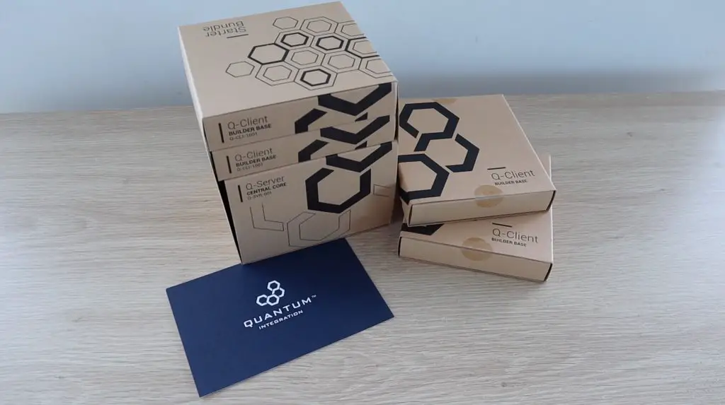
The Quantum Integration system is a wireless electronics platform that enables you to build IoT devices and apps quickly and easily thanks to an easy-to-use set of hardware and a drag and drop programming interface.
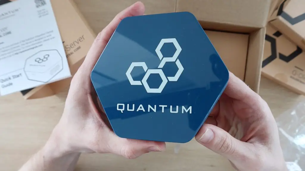
The heart of the system is a central server, this is where all your apps are stored and run. You can also access your apps and their control dashboards from any device on your network with a web browser.
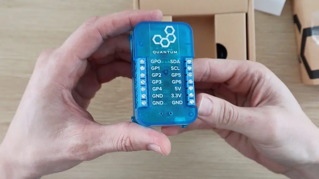
You use these Q-client builder bases on your projects and devices to bring them to life. Each builder base has 7 GPIO pins as well as a dedicated I2C interface. They’re also designed to be able to be used in low power applications, so are able to run for months on a single small battery.
You can currently connect up to 5 builder bases to your server at once and these can then be used on the same project or on different projects.
One of the strengths of the Quantum Integration system is its seamless wireless connectivity. You can easily build projects that communicate wirelessly between builder bases or between one or more builder bases and a customised web dashboard through your browser on a laptop, tablet, or phone.
What You Need To Build Your Own Indoor Hydroponic Farm
There are quite a few parts to this hydroponic project and a number of them may vary, depending on what you have available locally. I’ve put together this parts list that matches what I bought as closely as possible.
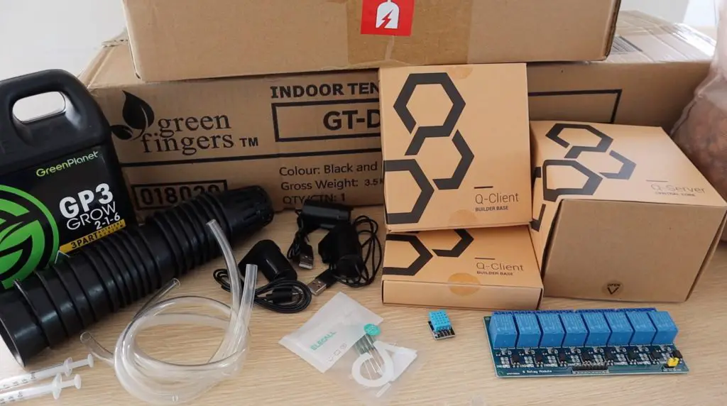
- Quantum Integration Starter Bundle – Buy Here
- 60 x 40 x 60cm Grow Tent (Similar Size) – Buy Here
- 600W LED Grow Light – Buy Here
- 2-3 x Storage Containers (Either Same Capacity or One Double The Other Two)
- 50mm Mesh Grow Pots – Buy Here
- Clay Grow Beads – Buy Here
- 1L Nutrient Solution – Buy Here
- 3 x 5V Pumps – Buy Here
- Flexible Tubing To Suite Pumps – Buy Here
- 8 Channel Relay Board – Buy Here
- DHT11 Temperature & Humidity Sensor – Buy Here
- I2C 16×2 LCD Display – Buy Here
- Breadboard Jumpers – Buy Here
- 3mm Acrylic (Optional) – Buy Here
- Nylon Standoffs (Optional) – Buy Here
How To Make Your Indoor Hydroponic Farm
Assembling The Grow House & Containers
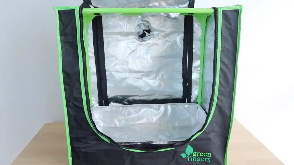
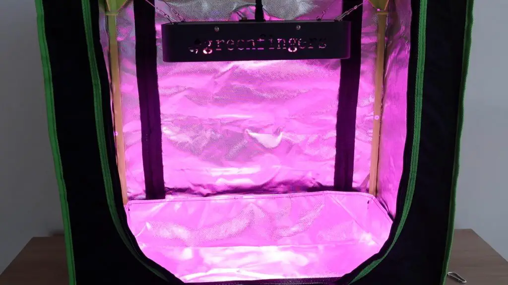
I started out by assembling the grow house. Mine is just a generic 60x40x60cm tent-style grow house which is quite commonly available online. You might not be able to find the exact same size as mine, but any similar size will do. I chose this smaller one because I intend growing lettuce and other small leafy vegetables that don’t need a lot of headroom.
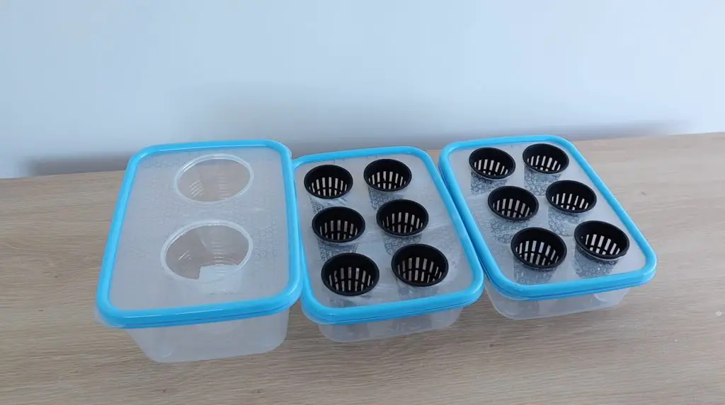
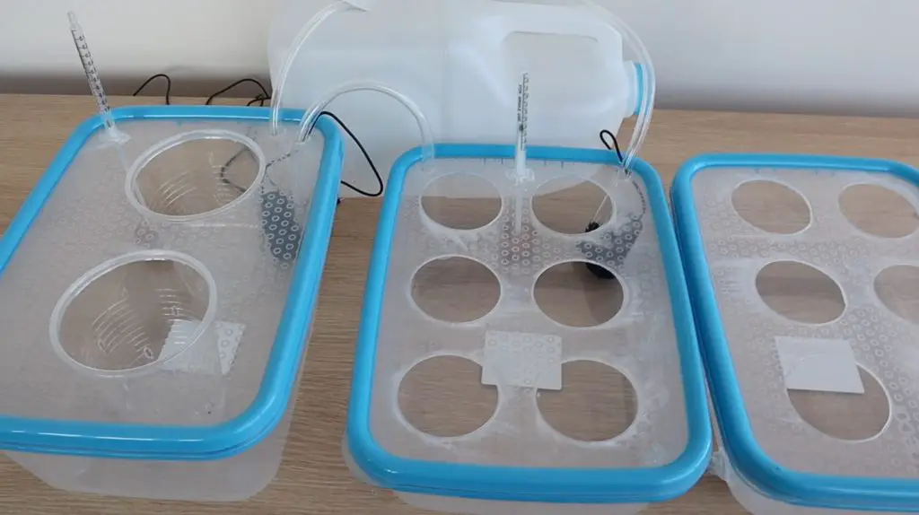
I bought three containers to use to hold the grow pots. Two smaller ones that could each hold six small hydroponic grow pots and one larger one for two larger grow pots. You can use any individual containers or combination of containers with the same volume as the nutrient solution will be pumped from one to the next. My large one holds 6 litres and my two smaller ones 3 litres each. I connected the smaller ones together with a couple of sections of tubing, so when one fills the other does too.
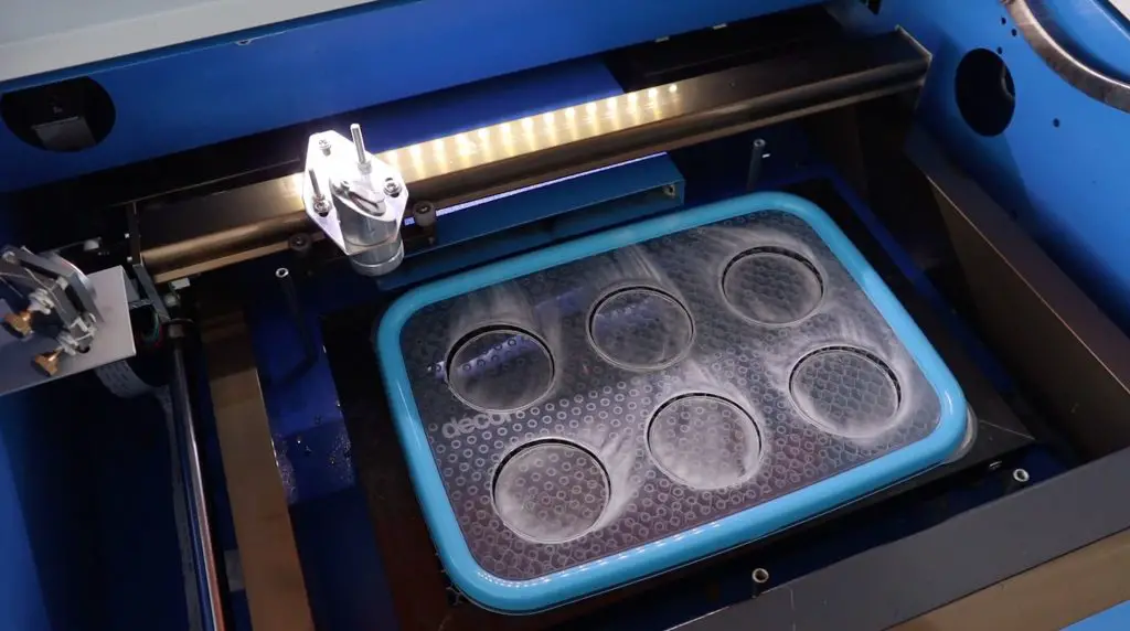
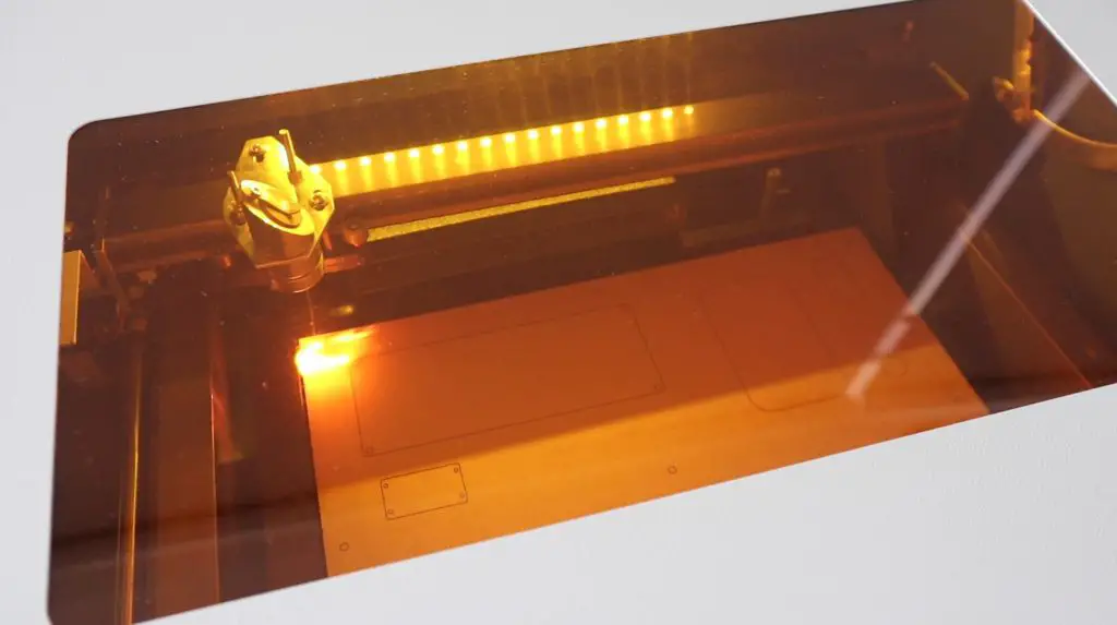
I measured the rim of my pots and then used a laser cutter to cut the lids of the containers to hold them.
I just used two plastic cups for the larger grow pots and used a soldering iron to make some holes in them for the nutrient solution to fill and drain from.
Attempting To Make Float Switches
My initial intention (and probably still my long-term goal) was to use float switches to control the levels in the containers. This would ensure that each container was properly filled and that the pumps wouldn’t run dry.
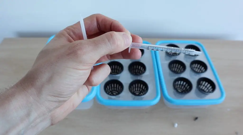
I looked at some local stores for small float switches but couldn’t find anything small enough for my containers, so I decided to try to make my own using some syringes, magnets and reed switches.
The basic idea was to use the syringe without the rubber seal as a guide for the float and to stick a magnet onto the end of the plunger to close the reed switch at a certain limit.
So I took the rubber part out of some small syringes I found and added a magnet to the end of the plungers.
I then glued a cork float onto the bottom of each plunger.
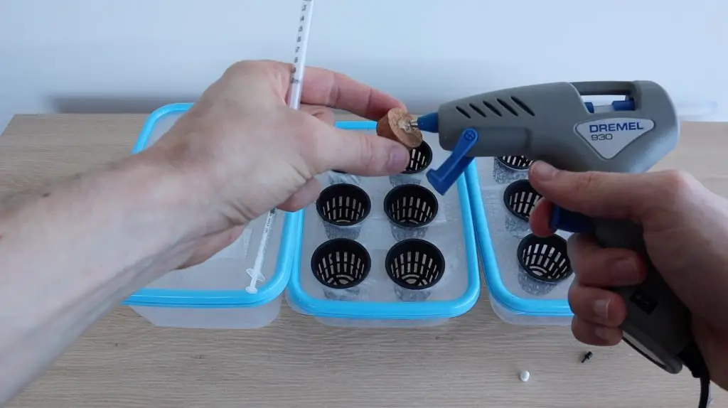
I then also glued a reed switch onto the side of the syringe to pick up on the position of the magnet and close the circuit when the water level gets to a certain point. This setup can be adjusted by moving the reed switch up and down on the syringe.
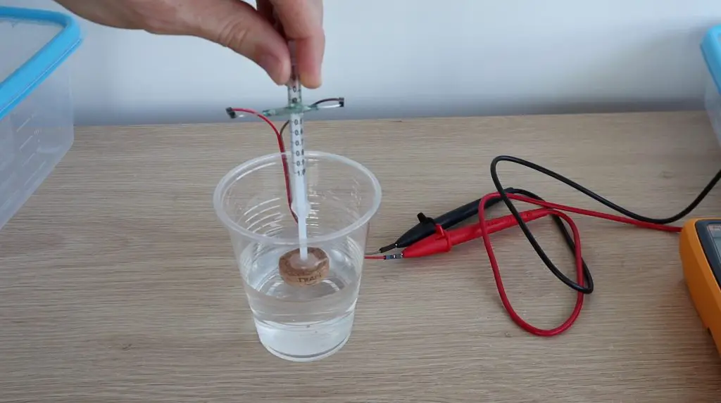
This worked pretty well for my cup test, but once installed on my containers I noticed that if the small magnets were rotated to a certain point, the magnetic field was no longer strong enough to close the reed switch. I also couldn’t use larger magnets as these were as big as could fit into the syringe already.
Preparing The Hydroponic Flood System
Now that the containers are prepared, we need a way to move the nutrient solution from the reservoir to container one, from container one to container two, and then back from container two to the reservoir. To do this, we’re going to use three small 5V pumps.
I just used a 3-litre milk bottle as my reservoir. You need to use a container that isn’t too tall or you put extra pressure on the small pumps and reduce the flow rate.
Put a pump into each of the containers and then connect them up with some flexible tubing. The ends of each tube should be pushed through the lids of the containers, but shouldn’t protrude too far as they might then siphon the solution back into the original container when the pumps are turned off. You want them each to pull in air when the solution runs back through the tube to the container it’s being pumped from.
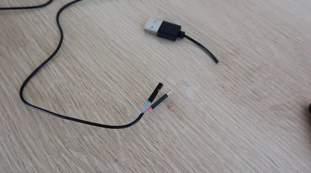
I cut the USB connectors off the ends of my pumps and replaced them with some Dupont connectors which can then be screwed into the terminals on the relay board.
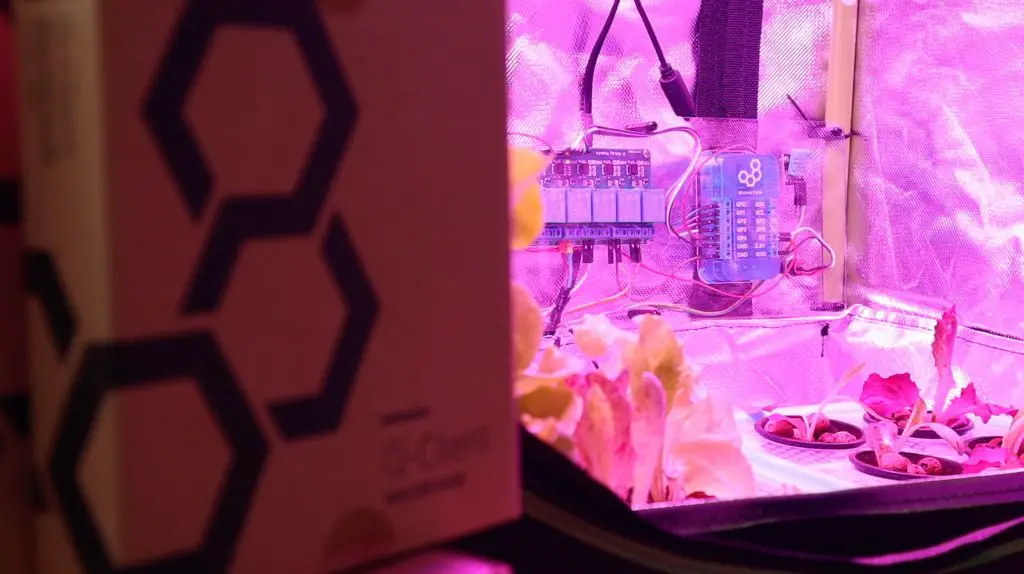
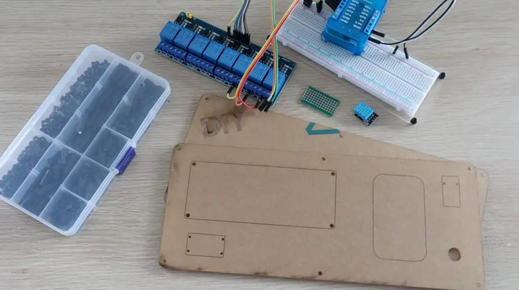
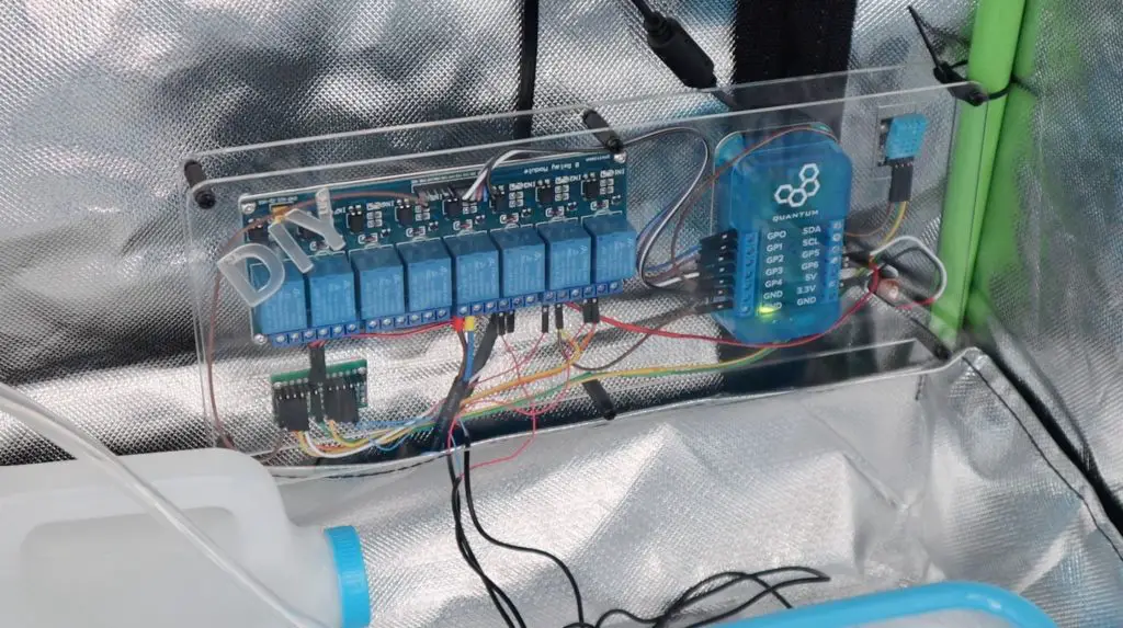
Connecting The Builder Base Control System
Now we need to automate the flood cycle using one of our builder bases and the relay board. The pumps are connected to individual relays and the builder base then drives the relays to turn each pump on and off.
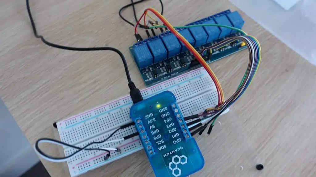
I have connected all of the negative terminals of the pumps to GND and the positives to the relay terminals which in turn then go to 5V. The relays act as a switch to turn the 5V on and off to each pump.
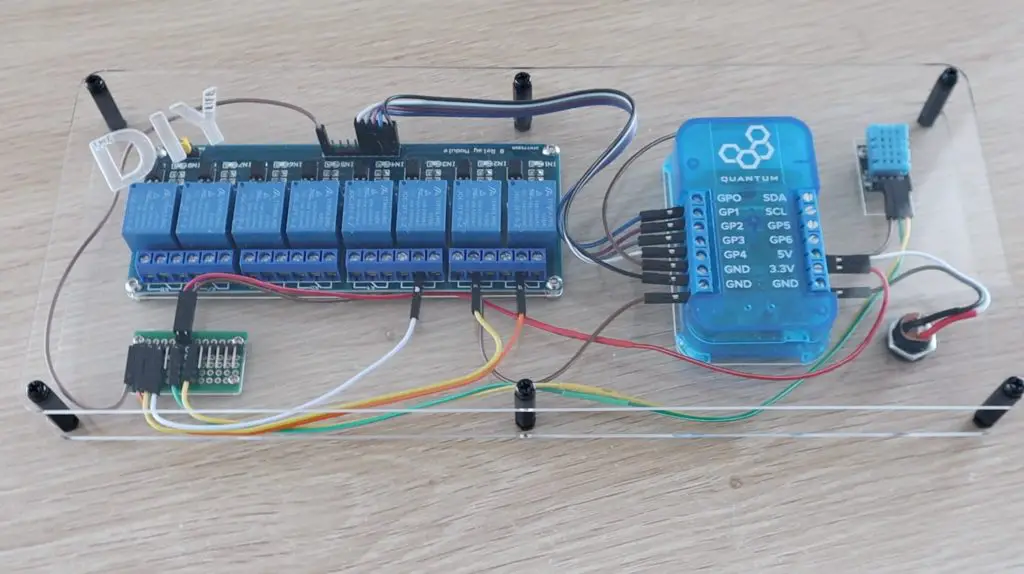
The builder base is connected to the input side of the relay board as follows:
- VCC to 5V
- GND to GND
- Relay 1 to GP0
- Relay 2 to GP1
- Relay 3 to GP2
- Relay 4 to GP3
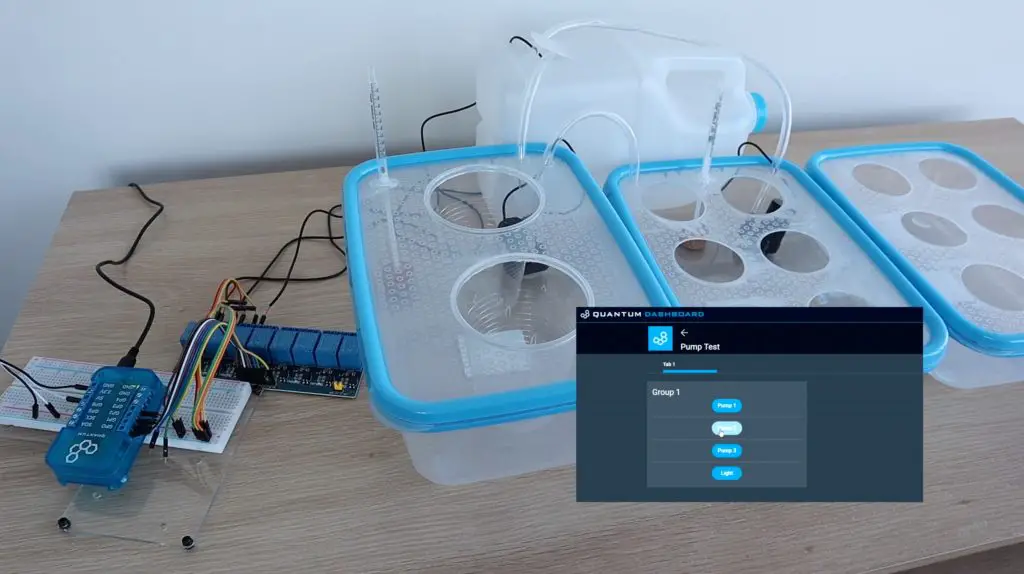
I then made up a quick demo app to test each pump and the grow light relay using a button on the web dashboard.
There was one minor complication that I found during this step. My relay board energises each relay by grounding the input pin, which is the inverse of my individual relay boards. So they are off with a 5V signal and on with a 0V signal. This requires the logic in the code to be flipped as well, so you’ll see a NOT gate ahead of each relay output in the app.
Automating The Hydroponic Grow Cycle
Once the pumps were working, I started working on the automated app.
The app consists of three sections:
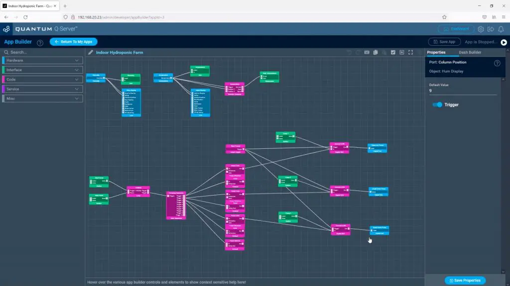
An environment tab, which displays the current temperature and humidity using the DHT11 sensor, as well as creates a notification alert if the temperature exceeds 30 degrees.
A pump tab, which has manual controls for each of the three pumps, similar to the test example, but also includes controls for the automated cycle. This runs each pump in sequence for the flood cycle and then waits for a period of time before executing the next flood cycle. From what I’ve seen online it looks like a good starting point is to flood your beds for around 5-10 minutes at a time and to repeat this every 2-3 hours.
Lastly, there is a grow light tab. The grow light tab has a slide switch to turn the grow light on or off and also has an automated cycle that turns the grow light on for a 10 hour period and then off for a 14 hour period.
There is a bit more to do than just create the app, you also need to generate and upload the firmware for each builder base, but this is quite straightforward and in essence just tells the builder bases what is connected to which pins.
You can download the app and firmware to import into your Quantum Cloud here.
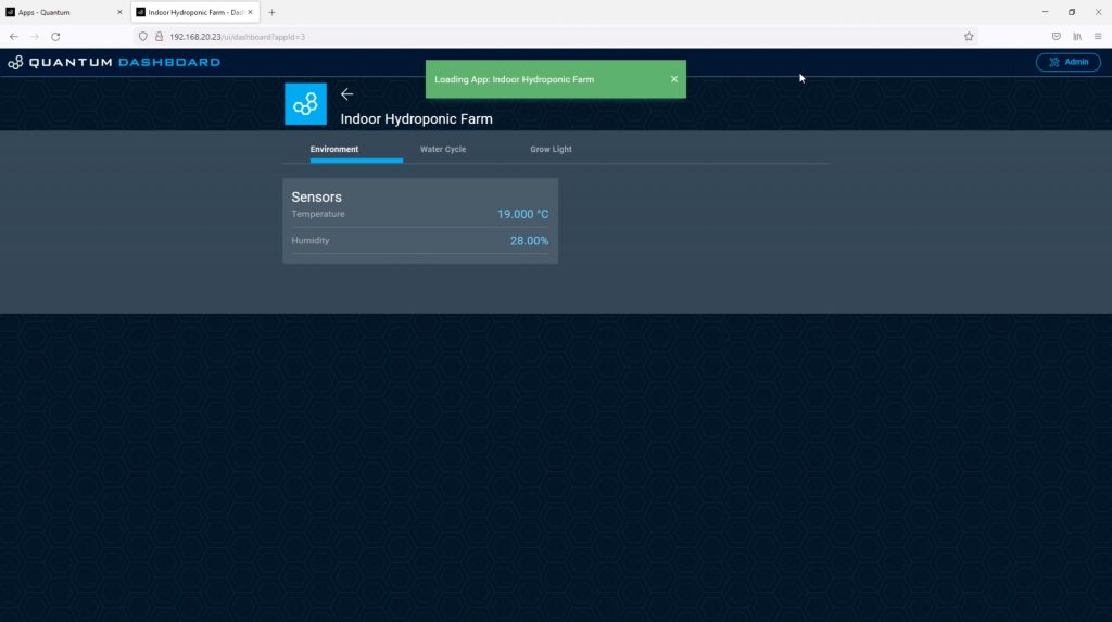
Once this is done, the dashboard can be accessed through the server and we can start using the controls.
The environment tab has the temperature and humidity readings from our DHT11 sensor.
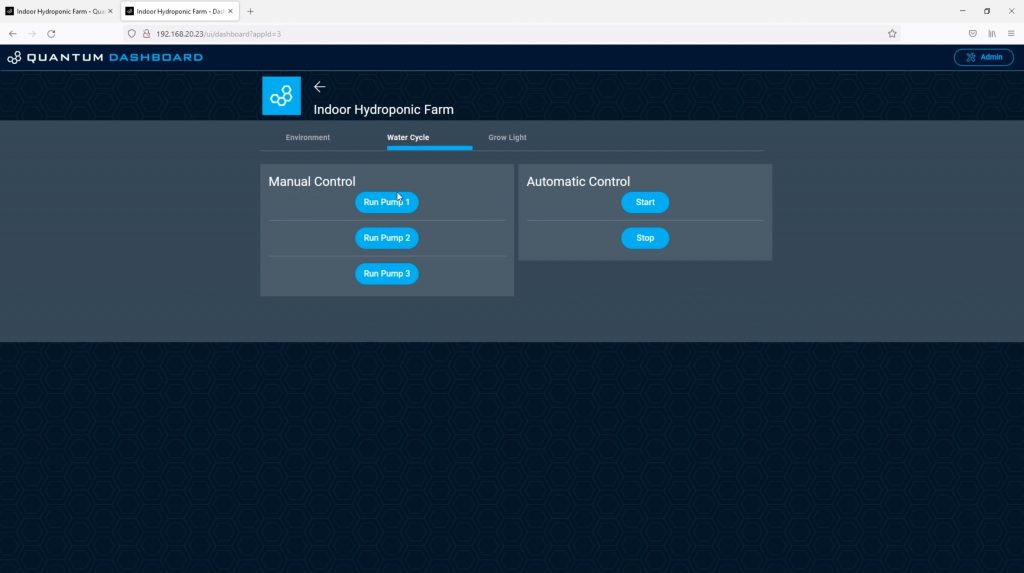
The water cycle tab has the three manual pump control buttons as well as the buttons to start and stop the automatic flood cycle. It’s worth mentioning here that if you push stop midway through the flood cycle, it’ll still complete that cycle before stopping.
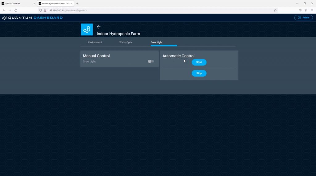
The grow light tab has a slider to turn the light on and off as well as buttons to start and stop the automatic light cycle.
You can see a clip of the automatic flood cycle running in my video at the beginning of the post.
As mentioned earlier, after a lot of trial and error, I couldn’t get the float switches to operate reliably. There wasn’t enough space in the small syringes to put a large magnet and the small magnets only triggered the reed switch when they were in a particular orientation. This was fine 90% of the time, but on the odd occasion when the switch didn’t close properly, it either flooded my desk or left one pump running dry. I did eventually found some small float switches online, but they’re on a long delivery, so I’ll only be able to put them in in a couple of weeks’ time. So the system runs on a time-based cycle at the moment. This works well for about two to three days and then needs a couple of minutes of adjustment using the manual pump controls, which is alright as a temporary solution.
Installing The Grow Light
The final part of our system is the grow light. We’ve already got the controls on our dashboard and the relay wired up to our builder base to turn the light on and off.
I hung the light in the grow tent using the included wire hanging loops.
Both the light and the light’s built-in switch operate at 220V. I made up a new power lead to replace the included one which had a branch off to the relay to enable it to be switched on and off remotely.
Note: Check your local regulations before modifying any cables or appliances, this often requires qualifications and/or permits. Also, do not attempt to do work on 110V or 220V AC supplies if you are not qualified or competent to do so, you run the risk of electric shock, which may result in injury or death, and you risk starting an electrical fire.
Making Up The Control System Housing
To support and protect the electronics, I made up some laser-cut acrylic panels to mount them onto. This panel could then be installed on the side of the grow tent.
There is a back panel to mount the components onto and then a front cover plate to protect the wiring. The cover plate will be mounted onto 6 nylon standoffs.
You could use a similar setup for a range of home automation projects as well. You’ve got a temperature and humidity sensor and also a relay board with up to 8 usable relays on it – although you’d need to use some relays together as you’ve only got 6 free pins on the builder base after the DHT11 sensor is connected.
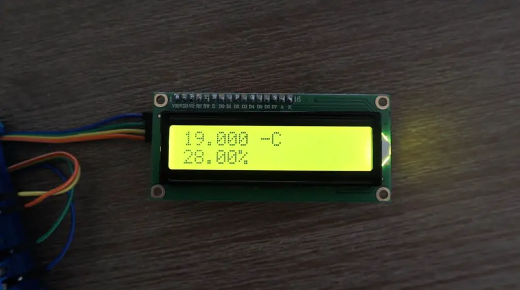
Adding A Remote LCD Display Panel
The last thing I’m going to do is to add a remote LCD display panel that can be used to keep an eye on the temperature and humidity in the grow tent from a different location. This will also be useful once my level sensors are installed.
This is as easy as dragging two LCD blocks into the app and dragging the sensor outputs to them.
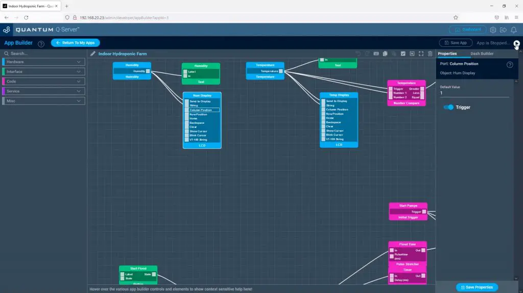
We can then connect the display to another builder base’s I2C interface and it’s ready to go.
- SDA to SDA
- SCL to SCL
- VCC to 3.3V
- GND to GND
Finishing Off The Hydroponic System
I connected the board to the pumps and grow light and then mounted it in the back of the grow tent.
I then started up the server and tested the pumps again, this time from my phone.
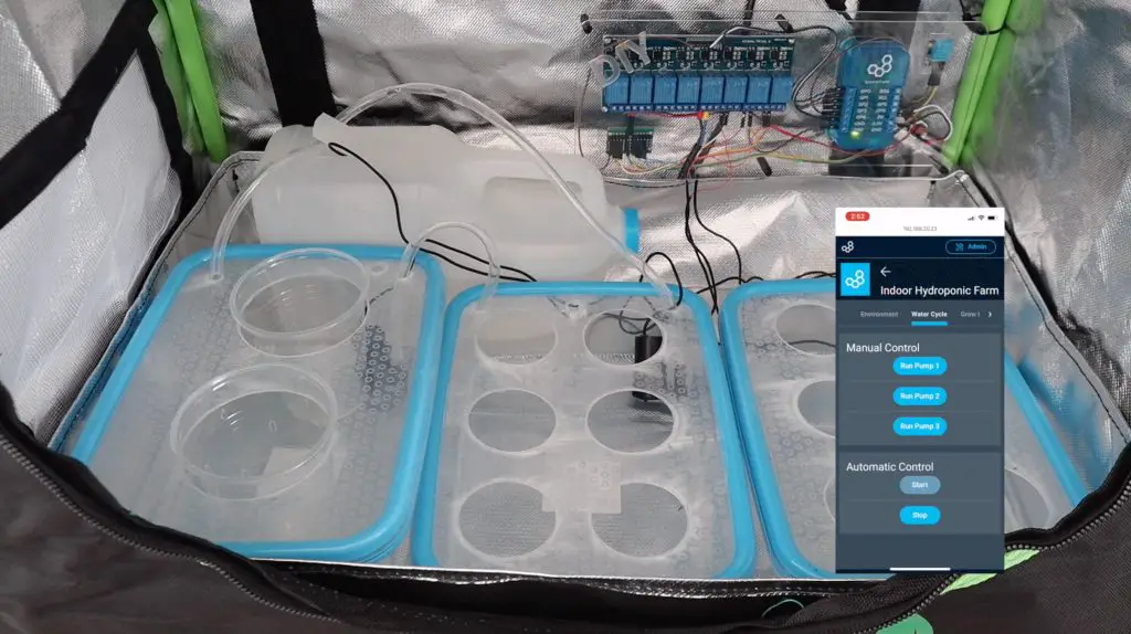
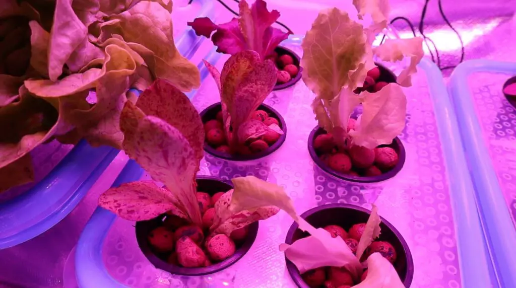
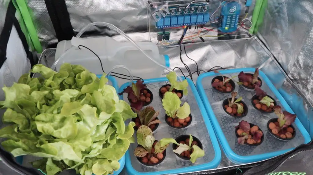
Once I was happy with the way the hydroponic system was working, I added the plants. As mentioned earlier, I’m going to be starting off by growing a few different types of lettuce. I’m pretty new to hydroponics as well, so I expect that it’s going to take some experimenting to see what works and what doesn’t. But I think the basics are all here and this will be a good start to indoor farming.
I hope you enjoyed this project. Let me know what you think of it in the comments section below and have a look at the Quantum Integration system if you’re looking at getting into building wireless or IoT projects.
If you’d like to build a simpler version of an indoor smart garden, have a look at my Micro:bit smart garden project.