Traditional soldering irons use a heated tip to melt solder in order to make electrical joints, while this works well when you have a mains outlet around, its not that practical when you’re out in the field. Anyone who’s done anything RC will know the frustration involved in a joint coming loose or a wire breaking off in the middle of a day out. You can buy a couple of different models of cordless soldering irons online but the main drawbacks are either lack of power or short battery life, the cold heat soldering iron addresses both of these problems. If anything it is perhaps a bit too hot and since it is only on instantaneously, you can make loads of joints (100+) before the battery runs flat.
The cold heat soldering iron works by essentially “short circuiting” the battery across the solder joint, the solder acts as a resistor, heats up really quickly and melts to form the joint as in the normal soldering process. The concept is similar to a traditional soldering iron in the way the tip is heated although in this case, the heated part is the actual solder and not a soldering tip.
What’s even better about this project is that it can be built using things lying around at home, there really is nothing complicated about it.
What You Need To Build A Cold Heat Soldering Iron
- A Scrap Piece Of Copper, Aluminium Or Brass Tubing (8cm/3″)
- A Thin Piece Of Scrap Glass (Or Mica, Plexiglass, Acrylic etc)
- A Short Length Of Ripcord Or Any 2 Strand Wire
- Some Pencil Lead (Graphite) Refills
- Heat Shrink Tubing or Insulation Tape
- LiPo Battery Plug To Match Your Battery
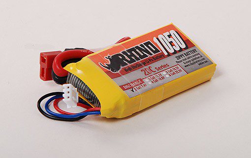
- A 1000mAh 2 Cell Lipo Battery (Or Similar Capacity 2 Cell)
- A Piece of Wood, Pen Or Dowel For The Handle – Alternately, Below Are Plans To 3D Print A Case For The Tip & Battery
Making Your Cordless Cold Heat Soldering Iron
Making The Soldering Iron Tip
The tip is the most important part of your soldering iron so it pays off to take some extra time to get it right.
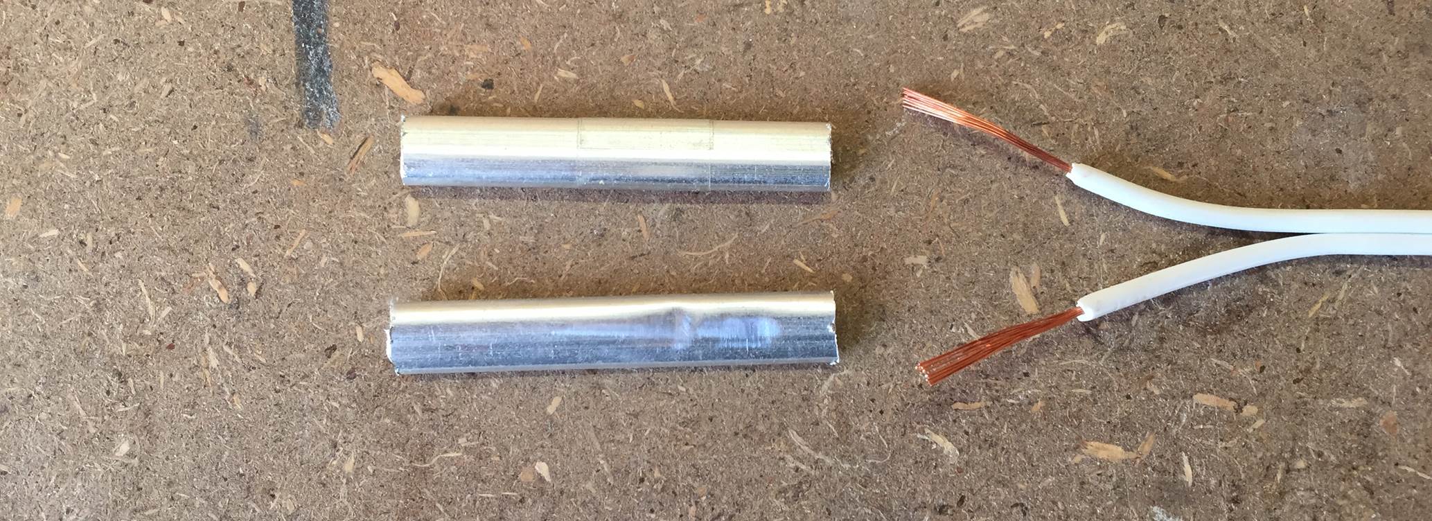
Start off by cutting your scrap piece of tubing into two equal sections of about 4cm or 1 1/2″ long, this doesn’t need to be all that accurate but it needs to be long enough to adequately support the pencil leads and absorb some of the excess heat created when soldering.
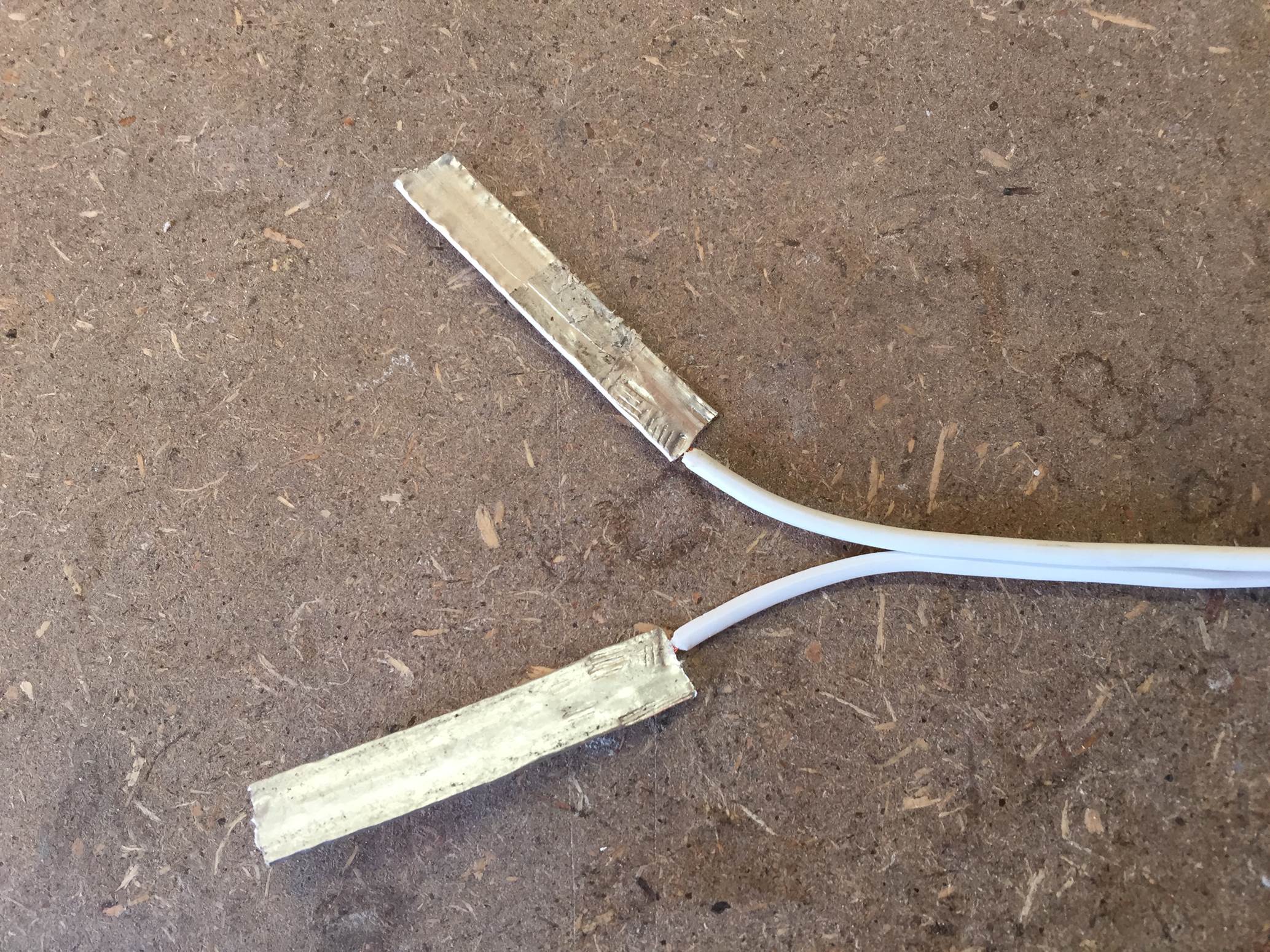
Now strip the plastic insulation off of the ends of your ripcord to expose the wire, the exposed wire should extend about halfway into the tubes with the edge of the insulation up against the tube ends.
Push each wire into the tube and then use a hammer or a pliers to squash the tube flat over the wire. Flatten the whole length of both tubes, these are going to be your contacts onto the pencil leads.
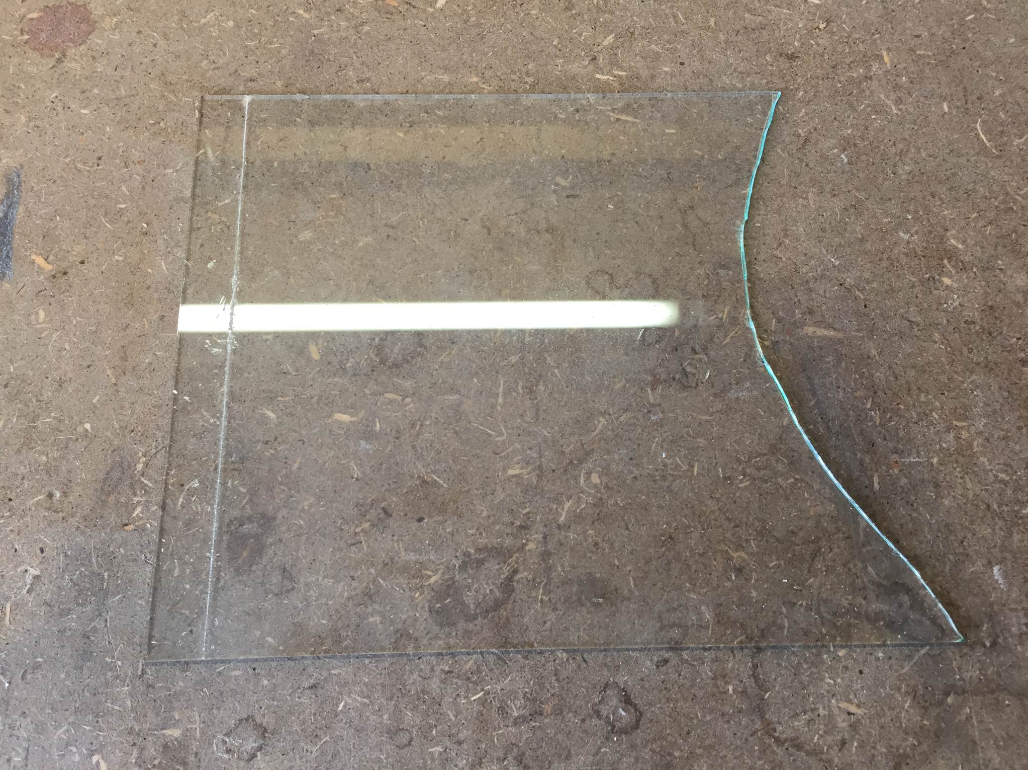
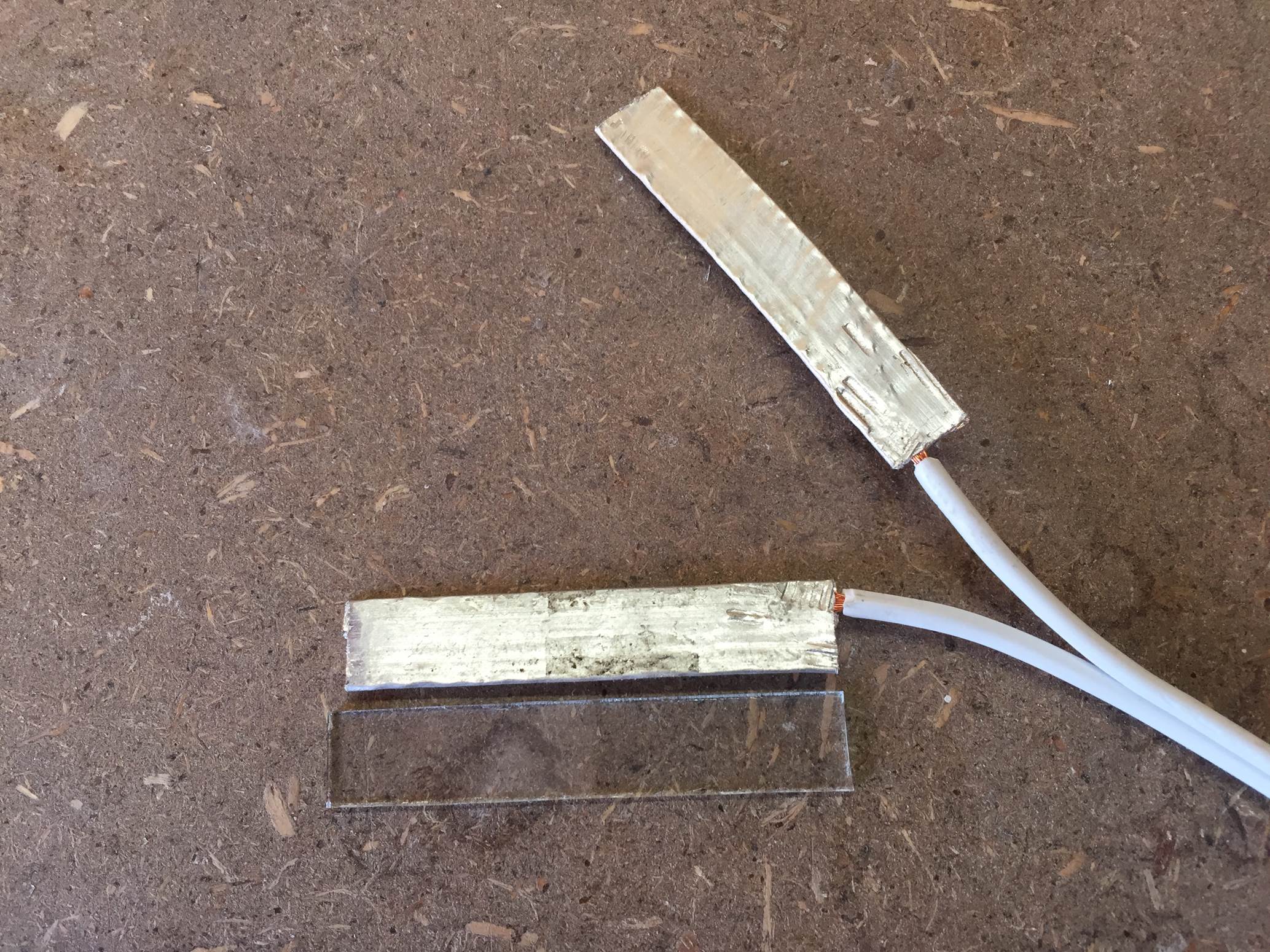
Now cut a strip of glass from your sheet of glass, the piece needs to be the same width and length as the flat tubes. In this case, the flattened tubes were about 1cm (2/5″) wide. Use a glass cutter to score the glass and then break off a strip of the correct width before breaking it to the correct length.
The glass strip should be a similar size to the flattened tube contacts when you are done.
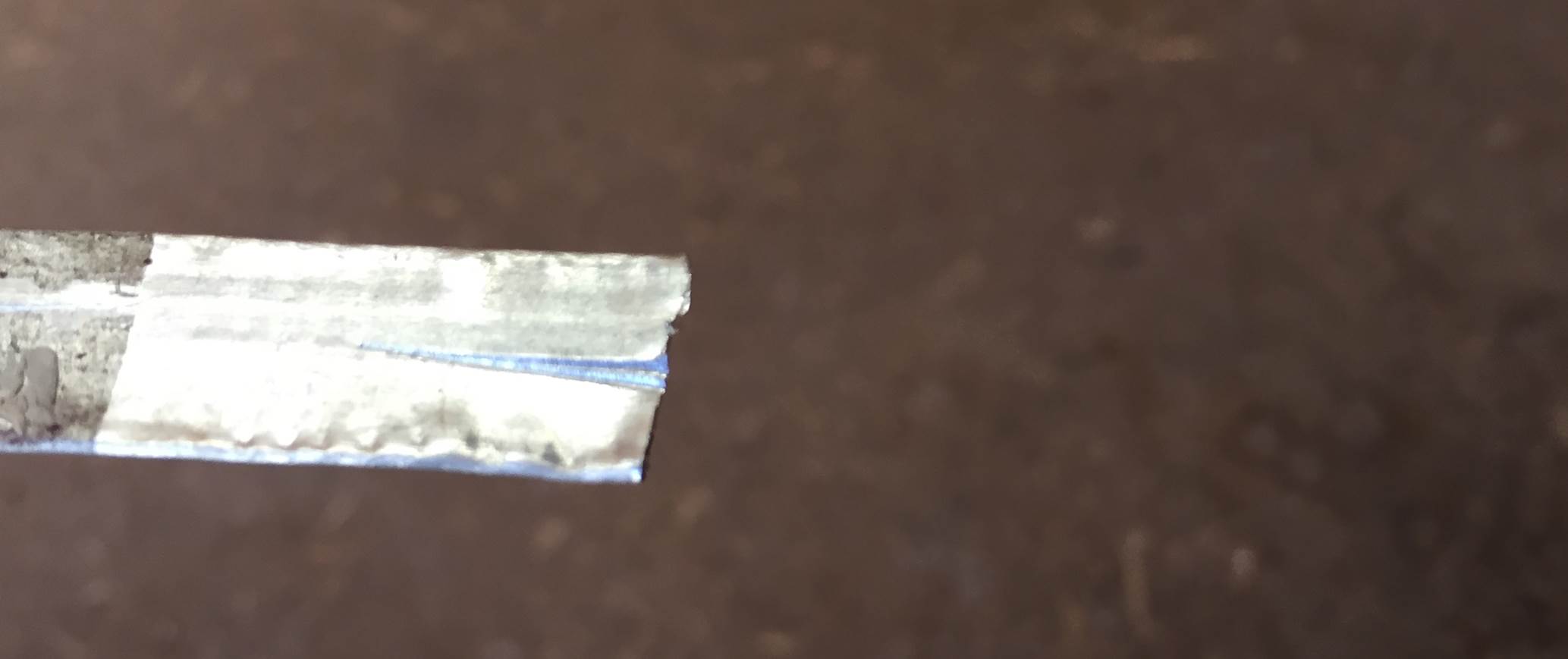
Before assembling the tip, you need to score the tubing so that the pencil leads are held firmly and in the centre of the tube contacts. Use a pair of side cutters, a craft knife or a Dremel to cut or score a line down the centre of each contact as shown below, the line doesn’t need to go the full way down the length of the contact.
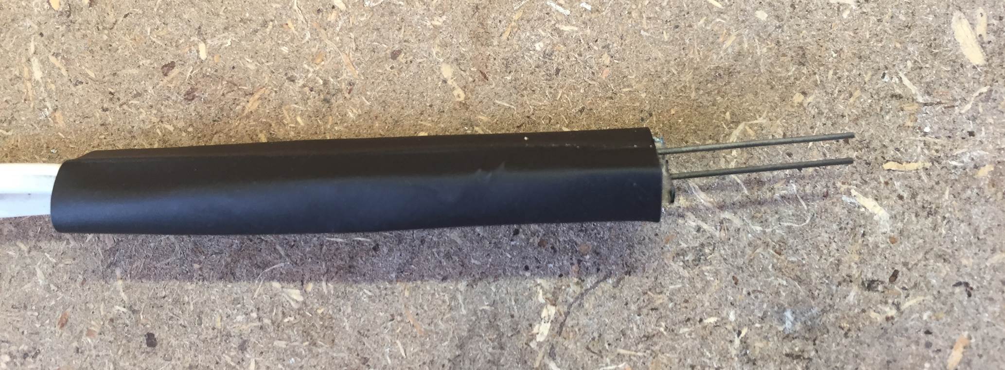
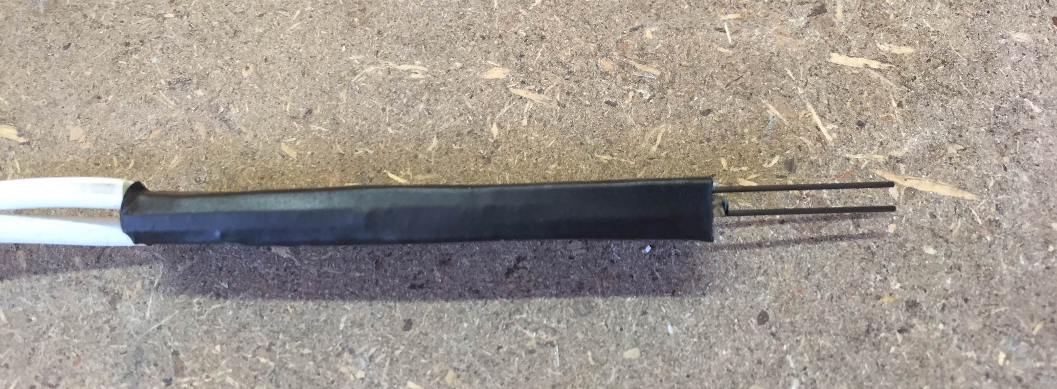
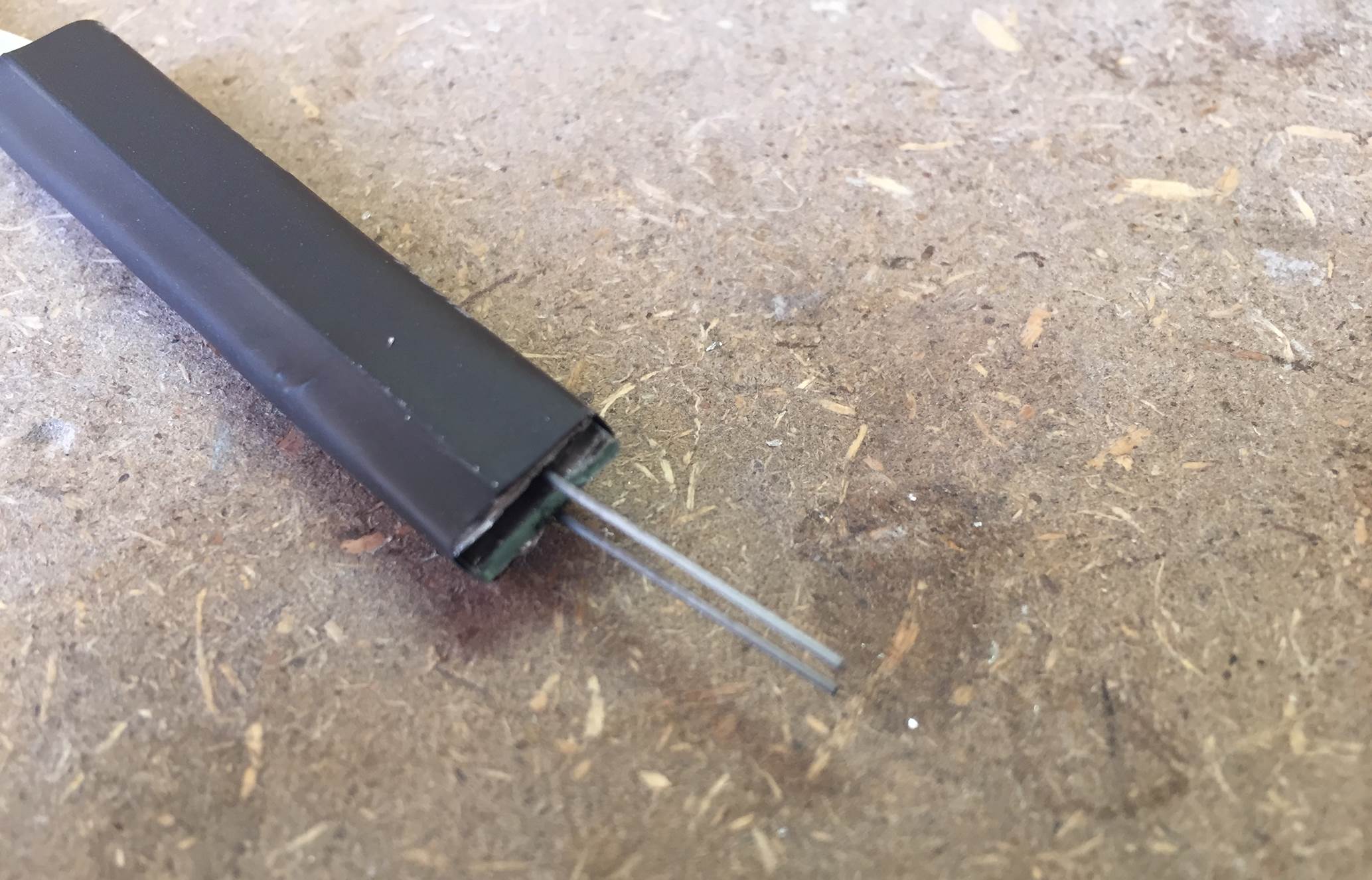
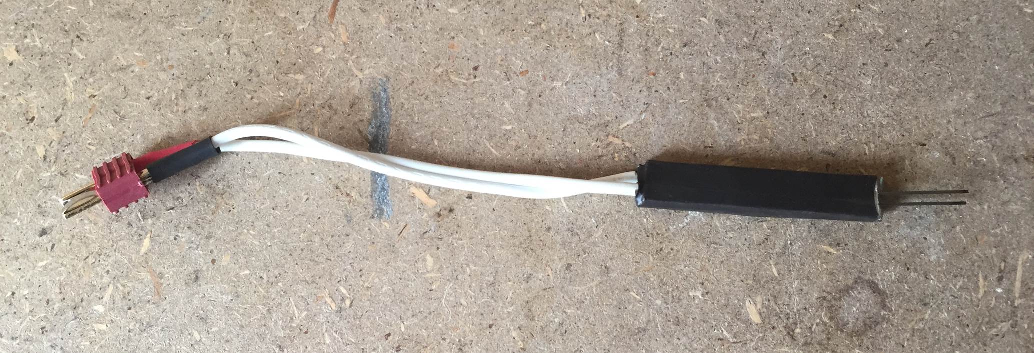
Assemble the tip by putting the glass strip between the two contacts with the score marks facing inwards towards the glass. Insert the pencil leads between the contacts and the glass, lining them up with the score marks, and then wrap the tip up with insulation tape or put a piece of heat shrink tubing around it.
Once you are happy with the position of all of the components and the alignment of the pencil lead, heat up the heat shrink tubing with a lighter, heat gun or blow torch briefly to shrink it together and lock the pieces in place.
The pencil leads should be close together but not touching each other when you are done. You will now need to be very careful when handling your soldering iron tip as the slightest bump will break the pencil leads, they are really fragile.
On the other end of the ripcord lead, you need to solar on your battery plug. The polarity (positive + and negative -) of the battery plug don’t matter for this tip so you can solder either lead onto either of the plug terminals.
The tip and electrical connections are now completed.
Testing The Cold Heat Soldering Iron Tip
Once you have completed your tip, you should probably test it and check that the connections are made correctly before you go through the effort of mounting it onto a handle or inside a case.
To test the tip, make sure that the pencil leads are not touching each other or anything conductive, they should preferably be raised a little off the counter or work surface. Now plug the tip’s lead into your charged LiPo battery.
With the battery plugged in, take a piece of thin strand solder and touch it against the two pencil leads simultaneously. It should smoke a little bit and then the solder will begin to melt. A little spark or the tips of the pencil leads turning bright orange is quite normal, just don’t allow the whole pencil lead to turn orange.
Shown in the video below is our test of the tip, we plugged the tip into a power monitor to check the voltage and maximum current when soldering to ensure that the current was not exceeding the batteries limit.
The battery voltage was 8.33V which is normal for a fully charged 2 cell Lipo and the maximum current drawn to melt the solder was 5.30A which is well below the batteries 20A limit. With a 1000mAh battery, you should get about 11 minutes of soldering before the battery needs charging. That’s 11 minutes of actual contact between the two pencil leads, which is a lot of soldering time, around 130 joints if each takes 5 seconds or so.
The power meter used to take these measurements can be found through this link.
Mounting The Soldering Iron Tip
Once you are happy with how your tip works, you can mount it onto a handle or rod so that it’s easier to use. A round wooden dowel works well as a handle and is relatively inexpensive. Tape the tip to one end and the battery to the other end, you’ll now have a neat pencil like portable soldering iron.
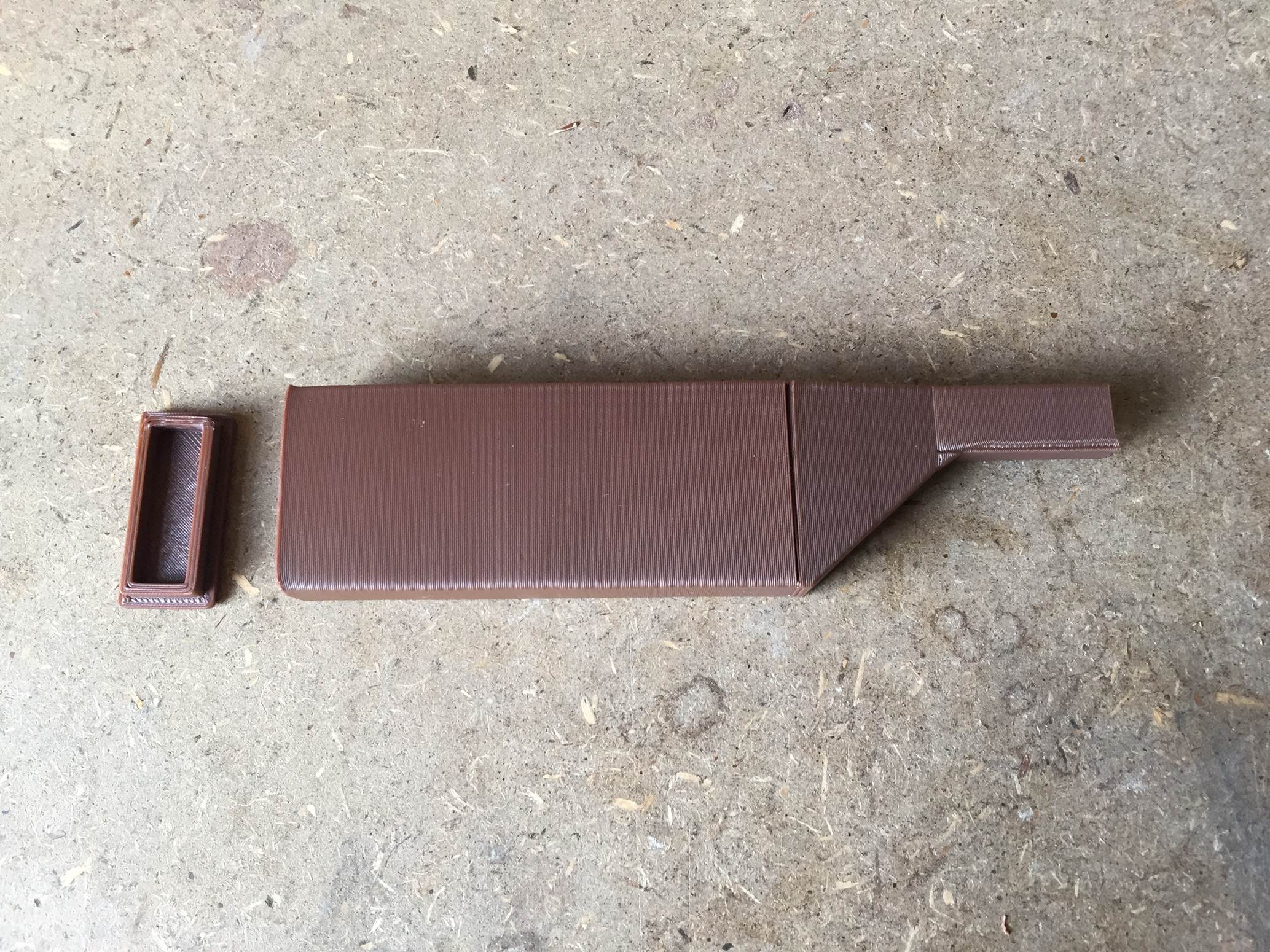
We decided to take it one step further and 3D print a case to house the tip and the battery. The case is printed in two parts, one is the actual case in which the tip is mounted and the battery fits into and the other is the end cap to close off the battery compartment.
You can download the 3D print model files here.
The case was designed for a 0.4mm nozzle printer but it can be printed with any printer with a suitable build volume. The material used was HIPS with a nozzle temperature of 225°C (437°F) and a bed temperature of 95°C (203°F).
Here is a timelapse video of the case being printed:
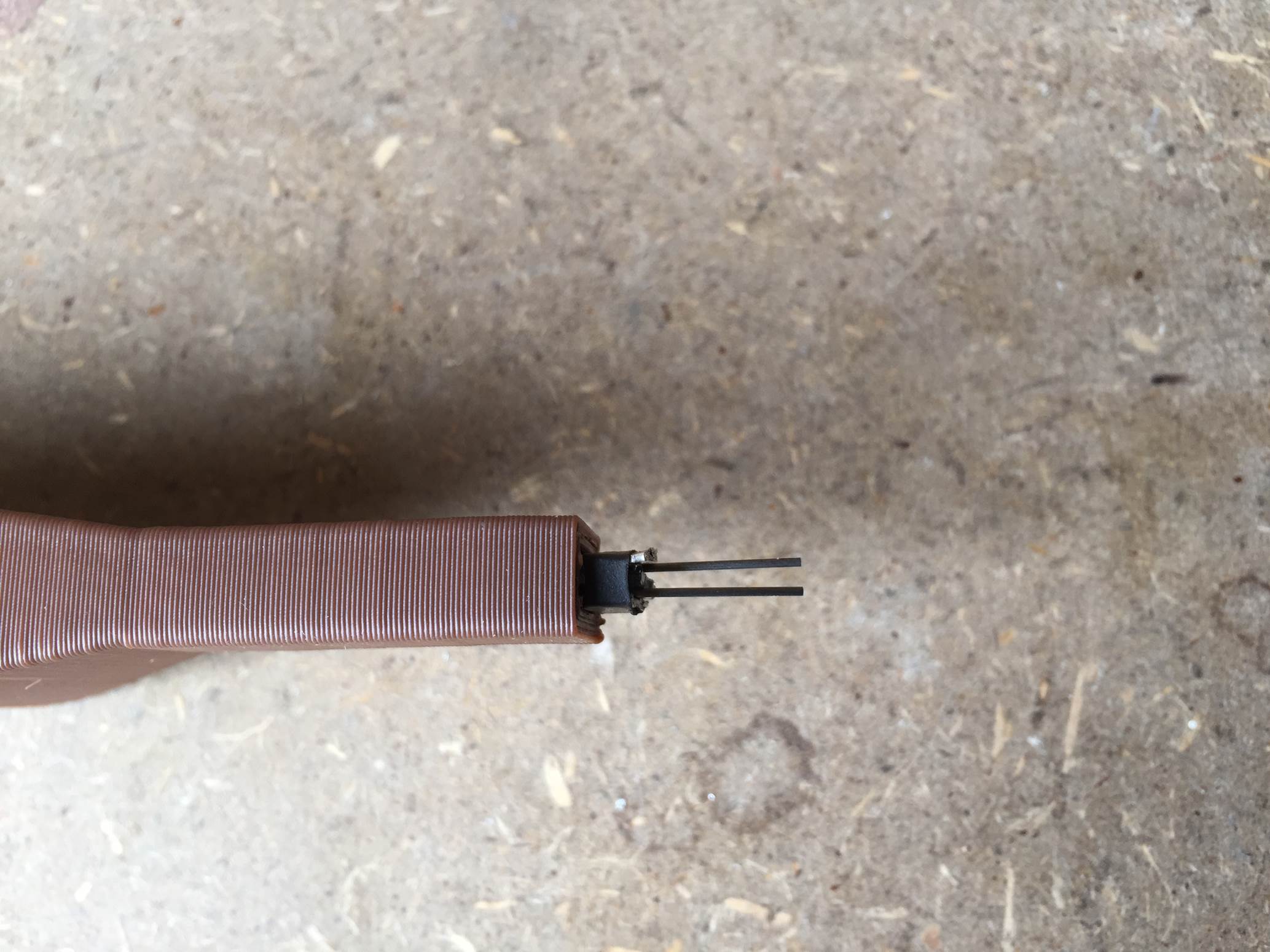
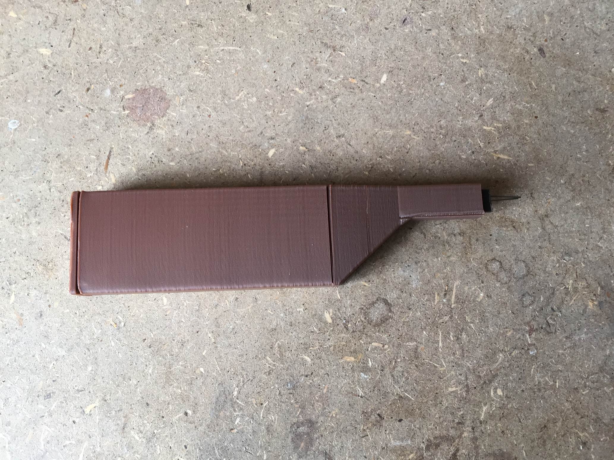
Once you have printed both pieces of the soldering iron case, the tip needs to be installed. The tip fits tightly into the front of the case, you may need to remove the pencil leads to push it into the case and then replace them afterwards.
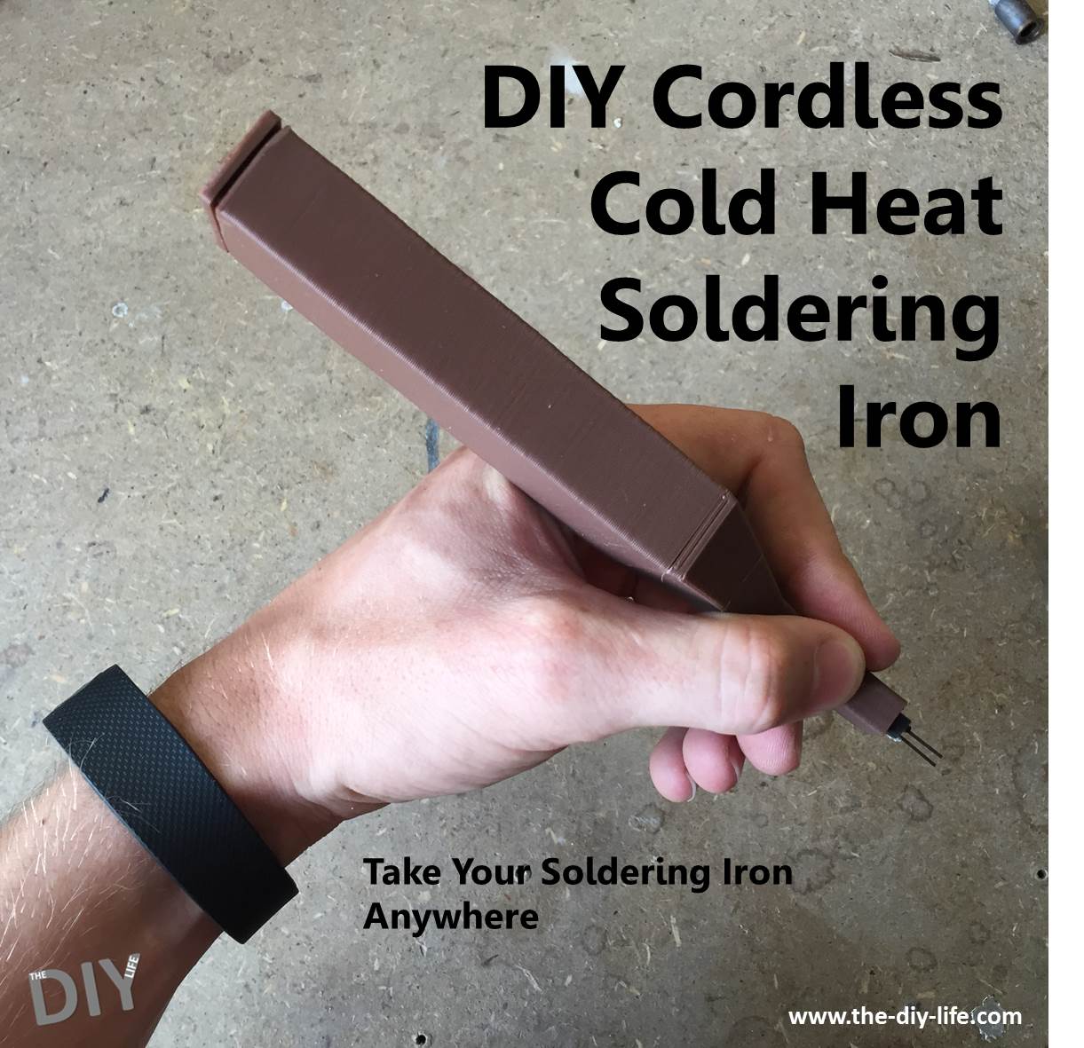
The complete soldering iron.
Using The Soldering Iron
Although the battery is effectively not in circuit when the soldering iron is not in use, you should always keep the battery unplugged when you are not using it to prevent something short circuiting the tip. A stray tool or screw in your toolbox may fall across the pencil leads and could cause a fire.
You can use any two cell battery you already have for your RC hobbies or whatever is available from your local RC store, it doesn’t need to be a high spec LiPo battery. A two cell battery has enough voltage and 1000mAh is enough capacity for a fair bit of soldering before it needs to be charged. To get more soldering time out of your soldering iron, use a battery with a larger capacity – 1500mAh or 2000mAh. We don’t recommend increasing the voltage (number of cells) above two, this design works quite well between 5V and 10V so a 2 cell LiPo is perfect.
To solder a joint, simply hold the soldering iron in one hand as you do with a regular soldering iron and then solder in another hand, gently touch the tip onto the joint and bridge the two pencil leads with the solder wire. The solder will melt and the joint will be formed. Do not press down on the pencil leads as they are extremely fragile and will break. It may be tempting to push down harder if the tip doesn’t heat up at first, rather move the solder wire around to a better angle.
Here is a video of two joints being made:
Some General Usage Tips
- Don’t attempt to solder any sensitive electronic circuitry with this soldering iron. There is a voltage difference across the tip which may damage sensitive components.
- Remember not to over discharge your LiPo batteries, use a battery monitor to alert you when the battery is running low.
- Keep the tip away from anything conductive when the battery is plugged in and always unplug the battery during transport.
- Work quickly, once the joint is hot, push the solder you need into the joint and stop quickly. The tips of the pencil leads may start glowing but don’t let the whole lead heat up, it will start to damage the heat shrink or insulation tape you used to hold the tip together.
- Don’t press down on the tip, the pencil leads are really fragile and will break if any pressure is applied to them. Rather move the solder around until it touches both ends of the pencil lead, this will cause it to melt.
- Try making a cap to protect the pencil leads when you’re transporting the soldering iron, this way you can leave it loose in your toolbox.
- You could use an RC brushed ESC to vary the voltage and current supplied to the tip for smaller or larger jobs, a servo tested could be used to give the ESC the reference signal.
Share This Guide:
Have you made your own cold heat soldering iron? Let us know in the comments section below, we would love to hear your tips and tricks.


