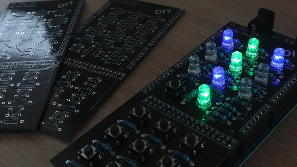
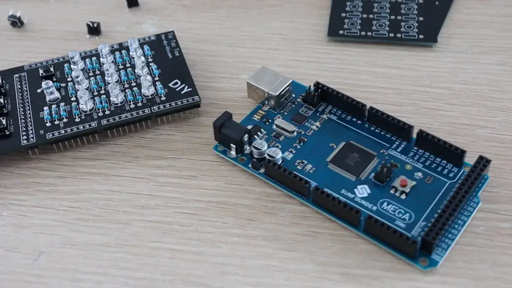
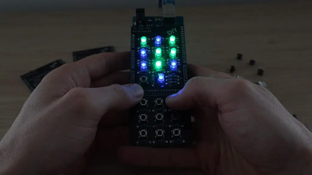
Today we’re going to be building a Tic Tac Toe or Noughts and Crosses shield for an Arduino. The game board is made up of a 3×3 grid of RGB LEDs that light up green or blue to indicate the naughts or crosses. A keypad at the bottom of the shield, that corresponds to the game board positions allows you to input each move. A status LED underneath the gameboard shows you which player’s turn it is and allows you to select one of the three game modes using the start button alongside it.
The game has 3 selectable game modes, the first is a turn-by-turn two-player mode that allows you to play against another person, the second is an easy level AI opponent and the third is an expert level AI opponent that is impossible to beat.
You can watch my video of the build below, or read on for the full instructions to make your own Tic Tac Toe game shield.
How The AI Algorithm Works
The AI works on a minimax algorithm, which is a recursive algorithm aimed at minimising the possible loss for a worst-case scenario. The algorithm calculates the value of each state of the game by looking at all of the possible outcomes following each move.
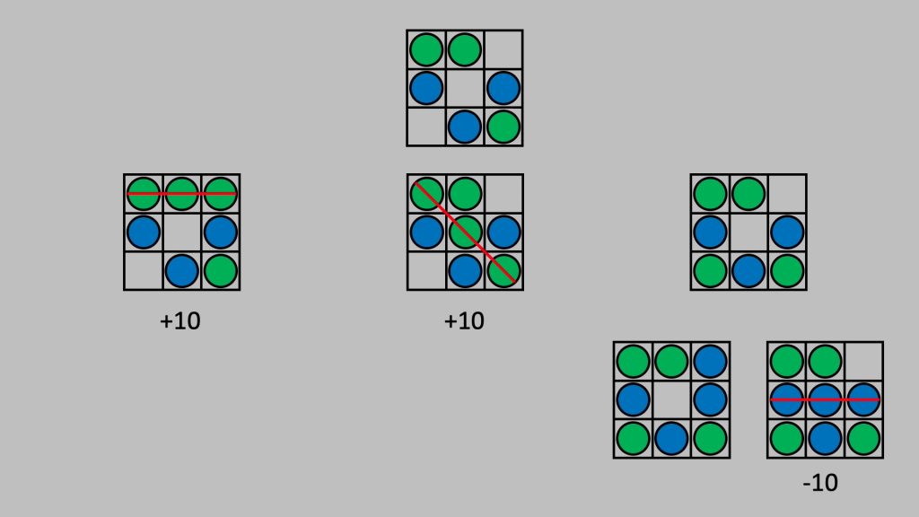
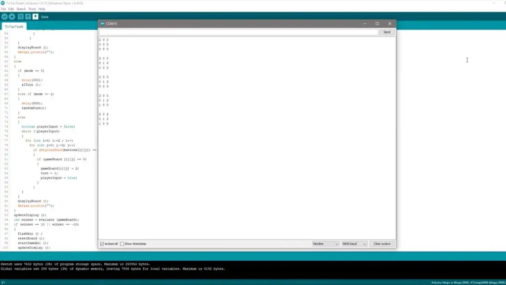
For example, the top game board below represents the current state of the game, with the green player to play next. The second line indicates the three possible moves that the green player can make. Two of these states result in the green player winning, these are awarded a score of 10. The third state allows the game to continue, with blue taking their turn. There are two possible spots for blue to play, the first does nothing (nothing in this move, although we can see that in the next move green would win) and then second results in blue winning. So, a score of -10 is given as this is against the green player who is currently playing. A state which results in an eventual draw is given 0. The algorithm would therefore favour one of the first two game moves, and work against playing the third move which allowed the opportunity for the blue player to win.
This is an old algorithm which was been around since the early 1900s and can be applied to many two-player, turn-based games. It’s commonly used in computer-based chess games to this day.
With the AI running the minimax algorithm on the Arduino, it’ll always play the best possible move, so regardless of who starts, you won’t be able to beat it.
To make the game a bit more fun, as it’s not much fun losing or drawing games all the time, I’ve added a second mode that plays random moves for the first two plays before allowing the AI algorithm to finish off the game. This drastically reduces the AI’s ability to win and you’re left with the possibility of winning most games that you start and a fair number of games that the AI starts.
What You Need To Make Your Own Tic Tac Toe Shield
Amazon Affiliate Links
- Arduino Mega – Buy Here
- 10 x Tactile Pushbuttons – Buy Here
- 10 x 5mm RGB LEDs (Common Cathode) – Buy Here
- 10 x 15K Resistors – Buy Here
- 11 x 390Ω Resistors – Buy Here
- 10 x 470Ω Resistors – Buy Here
- Male Header Strips – Buy Here
Banggood Affiliate Links
- Arduino Mega – Buy Here
- 10 x Tactile Pushbuttons – Buy Here
- 10 x 5mm RGB LEDs (Common Cathode) – Buy Here
- 10 x 15K Resistors – Buy Here
- 11 x 390Ω Resistors – Buy Here
- 10 x 470Ω Resistors – Buy Here
Making The Tic Tac Toe Shield
There are ways to use addressable LEDs to condense the IO to fit onto an Arduino Uno, but I already had a bunch of these RGB LEDs and an Arduino Mega lying around, so that’s what I used for this project. The shield makes use of 21 digital outputs for the LEDs and 10 digital inputs for the pushbuttons.
It is important that you get common cathode RGB LEDs as the PCB design incorporates a common GND and the IO switches high to turn them on. You can use common anode LEDs if you’ve got them already but you’ll need to modify the PCB to suit.
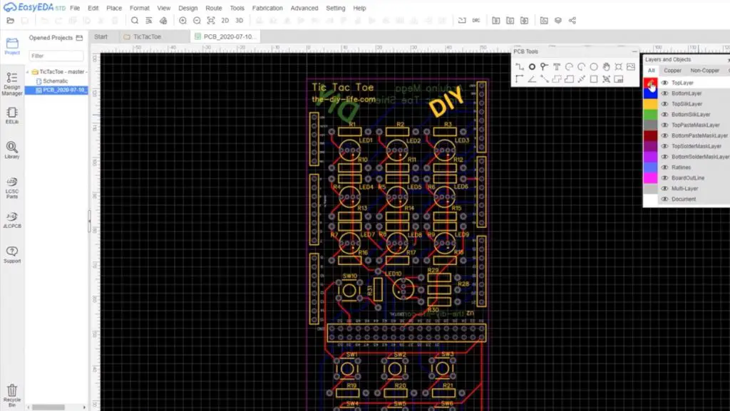
Designing The PCB
I sketched the circuit in Easy EDA and then designed a PCB as a shield that clips onto an Arduino Mega.

Each pushbutton has a corresponding 10-20K resistor and each LED has a 220-500 ohm resistor in series with it. I usually use slightly higher value resistors for the green legs of the LEDs as I find these are usually brighter than the blue and red legs. I didn’t connect the red legs of the LEDs on the gameboard as you only need to indicate two on states for each position.
You can download my PCB gerber files to have your own PCBs made up:
I got the PCBs made up by PCB Way. They have a really easy-to-use instant quote and ordering system and you can get simple PCBs under 100mmx100mm made up from just $5 for 5 pieces.

Soldering The Components Onto The PCB
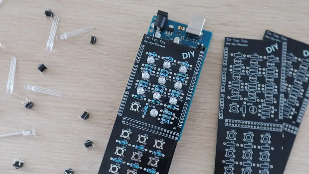
Once the PCBs arrived, I got to assembling them.
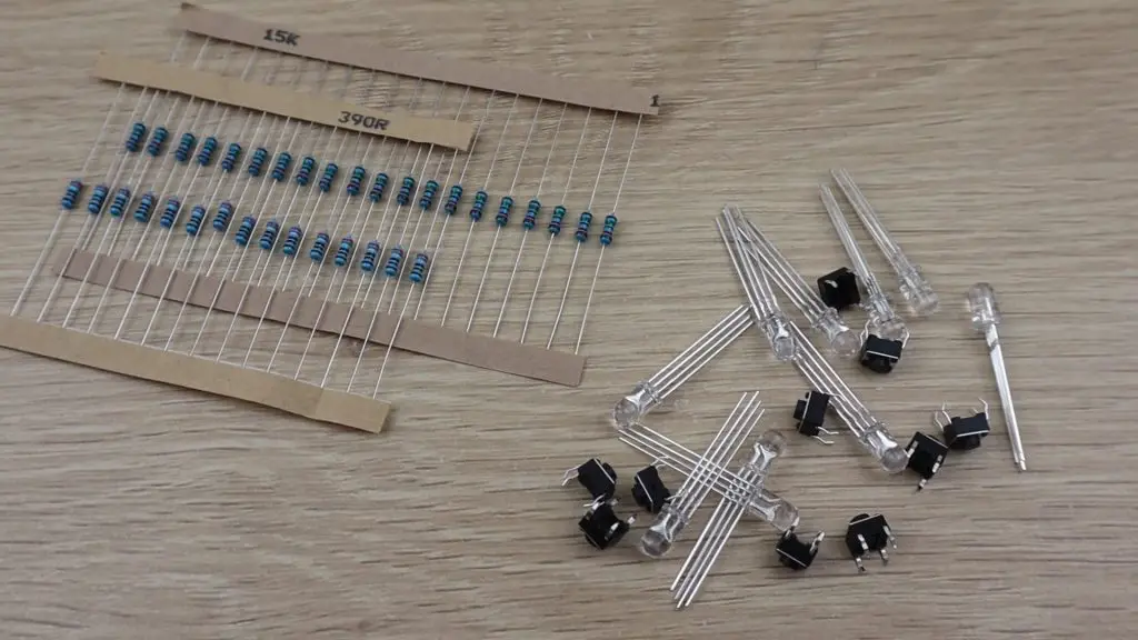
I used 15K resistors for the switches, 390-ohm resistors for the blue and red LEDs, and 470-ohm resistors for the green LEDs.
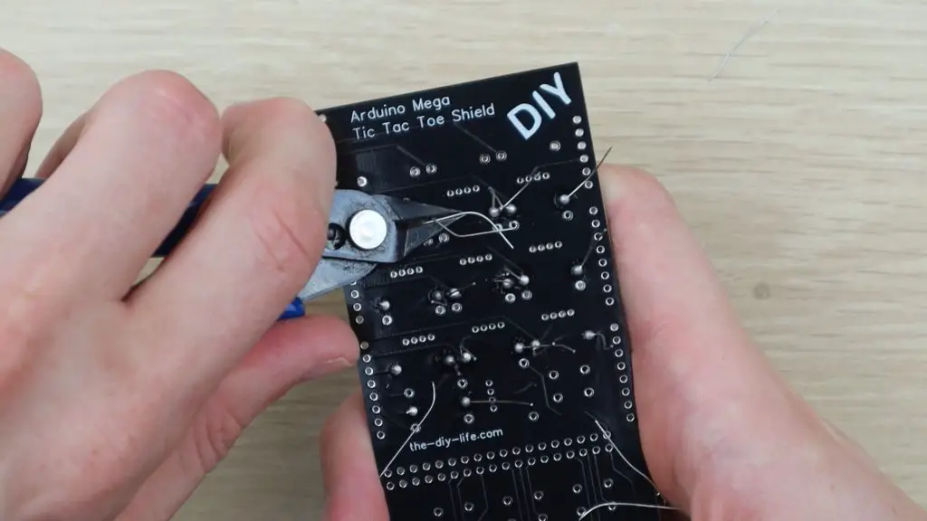
I soldered all of the resistors in place first and then trimmed the legs off the back of the PCB.
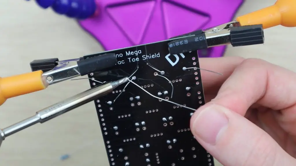
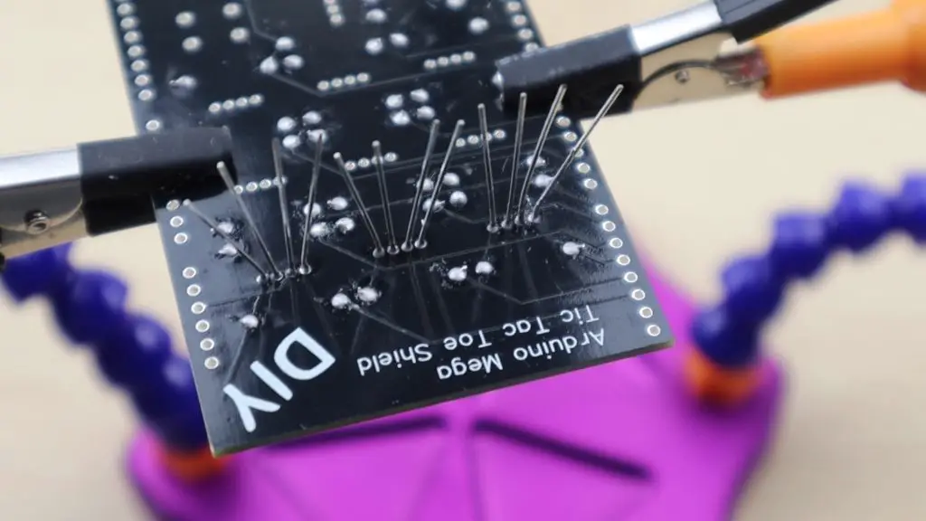
I then soldered the RGB LEDs into place. Make sure that the cathode (long leg) on the LEDs is placed into the hole with the small arrow underneath it.

Check all of the solder joints on the LEDs afterwards to make sure that there are no bridges across the pads or legs, they are really close together.
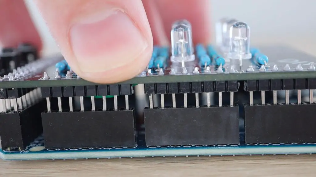
I also added some header strips to plug into all of the pins on the Arduino so that the shield is held in place firmly.
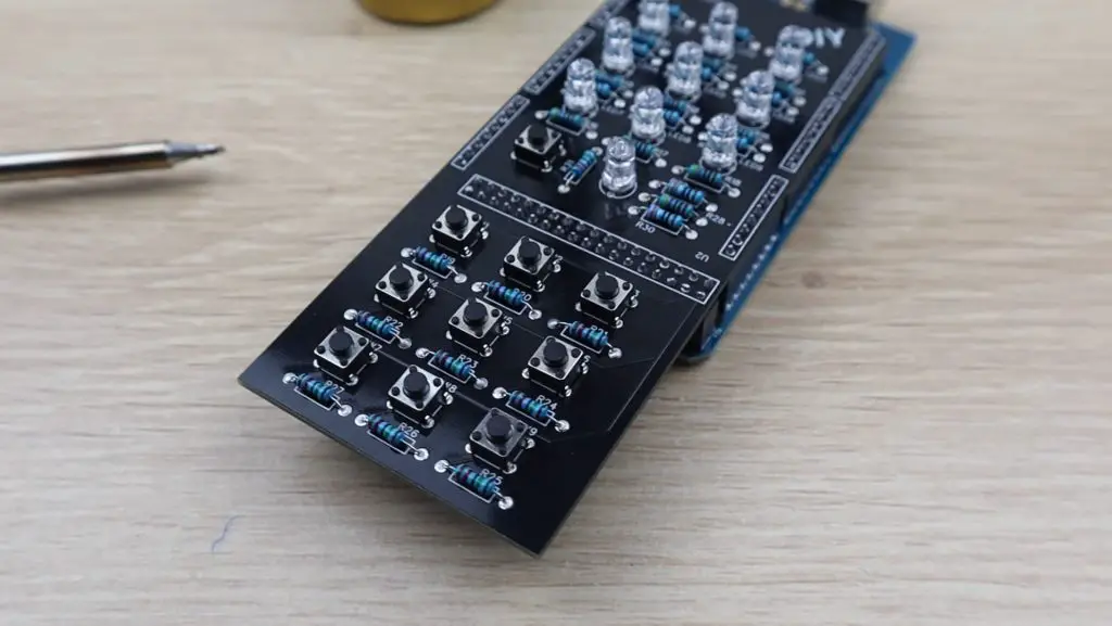
Lastly, you need to solder the tactile pushbuttons into place. Make sure that you’ve got the orientation correct before you solder them.
Programming The Arduino
With the PCB done, we can get started with the programming.
I started out by getting a game board set up in a 3×3 array and adding some logic to get the two player mode working. This allowed alternating green and blue inputs until the board was full or one player had won across the rows, columns or two diagonals.
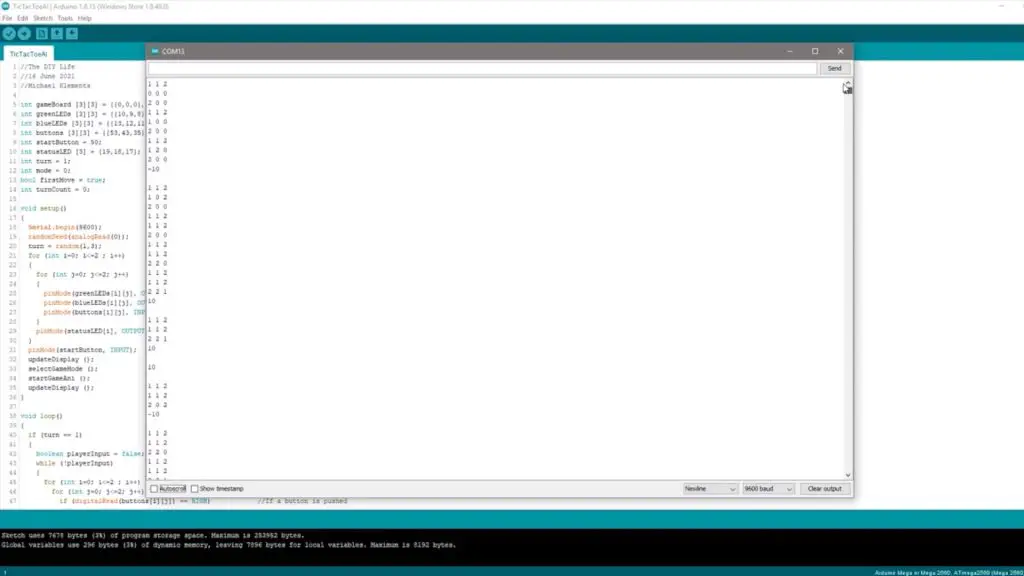
I used the number 0 to indicate a blank space, 1 to indicate player 1’s moves and 2 to indicate player 2’s moves. I set up the board to be displayed in the serial monitor for debugging.
Once this was working I got started on the AI’s minimax algorithm. If you’ve ever used this algorithm before then you’ll probably know that it’s not that easy to debug. It took me a couple of hours to get it working, and it finally started producing meaningful results.
I had to add some simple logic to the first AI move in order to reduce the first move’s processing time. The Arduino, being a relatively slow computer, was taking a significant amount of time to work through all 255,168 possible game outcomes if it was to play the first move and also took a consiberable amout of time if it was playing the second move.
With my modification, the AI essentially now plays a corner as its first move unless it goes second and the human player has already played a corner, in which case it plays the center position. This logic reduces the number of possible game plays to a couple of thousand, which the Arduino has no problem calculating in a few milliseconds. You’ll notice in my video of the gameplay that the Arduino takes a bit longer to play its second move than it does to play subsequent moves. This is the Arduino “thinking” through all possible moves.
Once the AI player was working, I added the final game mode that just chooses random board positions for its first two moves and then allows the AI to take over. This results in a game in which you can quite easily win if you play first and still allows the AI to occasionally win if it goes first or you make a silly mistake. You could add a fourth mode that only randomly places the first AI move. This would increase the difficulty quite a lot but still allow you some chance of winning if the AI got unlucky with the placement of this move.
I then added a start animation and code to highlight or flash the winning lines and the programming was then complete.
You can download the final version of the code here:
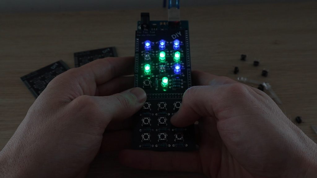
Playing Tic Tac Toe On The Shield
You can now select a game mode when the Arduino is powered up by using the center top and bottom buttons on the gamepad to scroll up and down through the three modes and pressing the start game button to confirm the mode. The current mode is indicated by the RGB status LED:
- Easy AI Mode – Green
- Expert AI Mode – Red
- Two Player Mode – Blue
Once in a game mode, the Arduino stays in the mode and just keeps refreshing the game board after each play. You can then keep playing in this mode until you reset it again.
Once a game mode is selected, the RGB status LED indicates which player’s turn it is. This is randomly generated for each game so that you don’t always have one player starting.
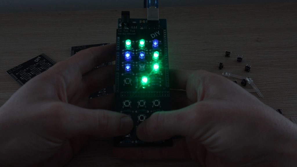
You can then play out your game and the Arduino will highlight a winning line once it is reached or flash the whole game board if it is a draw.
Let me know what you think of the game and what you would do differently in the comments section below. Enjoy making your own one!
This is awesome!
Nice, thanks for sharing.
When in mode=1 (random play) and it switched back to AI it still has firstMove set true and if location 1,1 is in uses it often overwrite it as it assume if a corner is not free 1,1 must be but at this point 4 pieces are already on the board.
Also the random play case statement is for 1 thru 9 but random number is for 0 thru 8 so bottom corner case 9 is never selected.
Thanks for picking those up KenL, I’ll have a look at them.
Is there anyway that I can I use Arduino nano or uno instead of mega
Hi to every one, it’s genuinely a good for me to go to see this site, it contains helpful Information.