Today we’re going to be using the new Arduino Uno R4 WiFi to build a controller for a PET bottle recycler. I’m doing this as the first part of a project, working towards building my own version of a PET bottle recycler to produce filament for my 3D printer. I already have an idea of what I want the machine to look like mechanically, so for Part 1 I’m going to focus on building the electronics to provide temperature control of the 3D printer hot-end and to drive the extruder motor.
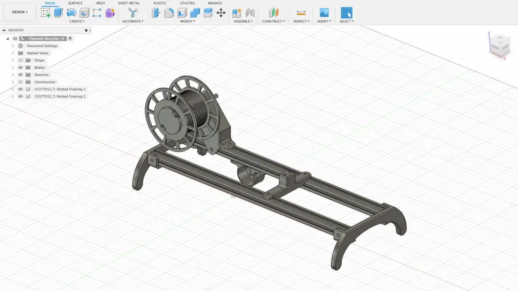
I have now completed the PET Bottle Recycler, you can find Part 2 here.
Here’s my video of the build, read on for the written guide;
What You Need For This Project
- Arduino Uno R4 – Buy Here
- Ender 3 Hotend – Buy Here
- IRFZ44N Mosfet – Buy Here
- I2C OLED Display – Buy Here
- 1/2W Resistors – Buy Here
- Capacitors – Buy Here
- TMC2208 Stepper Driver – Buy Here
- Nema17 Stepper Motor – Buy Here
- Rotary Pushbutton – Buy Here
- 2 Pin Screw Terminals – Buy Here
- Barrel Jack Socket – Buy Here
Tools & Equipment Used
- InfiRay P2 Pro Thermal Camera – Buy Here
- Jobi Gorilla Pod – Buy Here
- USB C Electric Screwdriver – Buy Here
- Hakko Soldering Iron – Buy Here
- Hakko Brass Insert Tips – Buy Here
Some of the above parts are affiliate links. By purchasing products through the above links, you’ll be supporting my blog, at no additional cost to you.
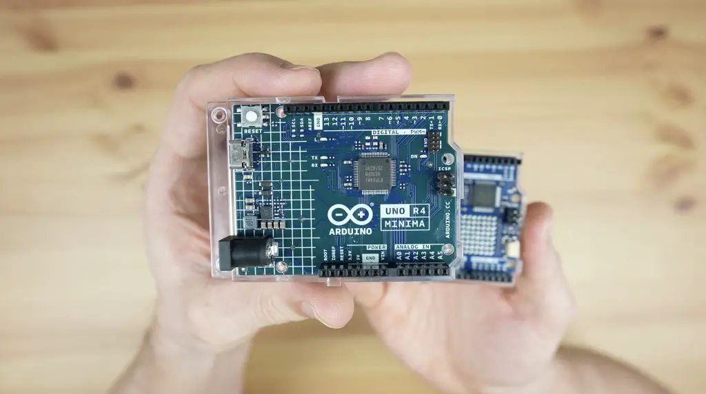
Arduino Uno R4 Minima & WiFi
I’m going to start the project by using an Arduino Uno R4 for prototyping. The Uno 4 comes in two versions, the minima which is the more basic version and then the WiFi version which has WiFi and an integrated LED matrix.
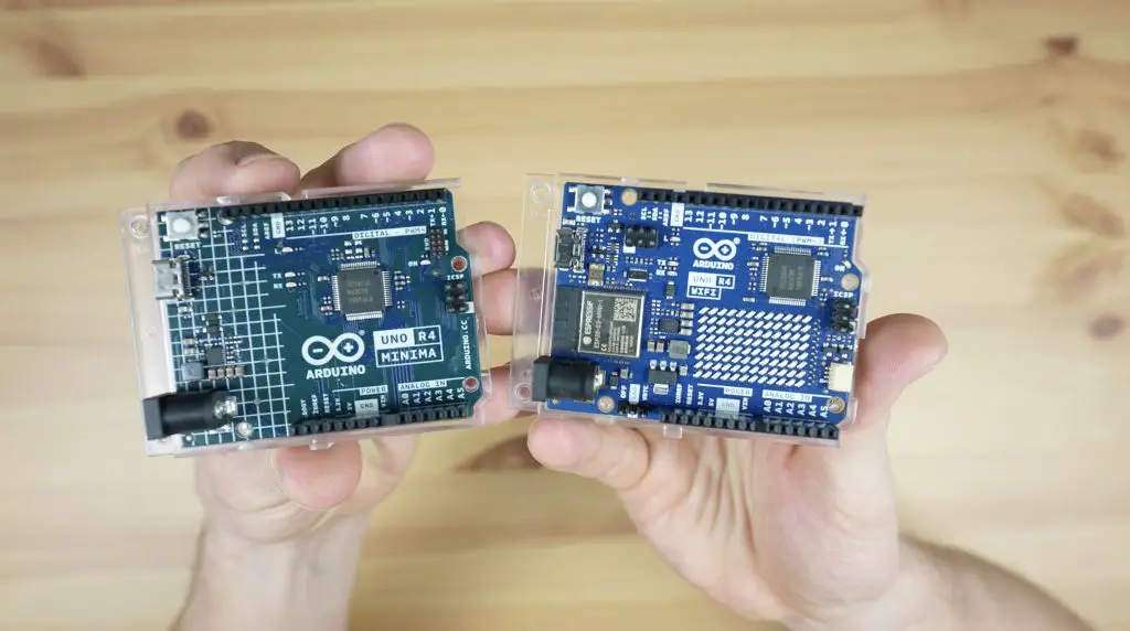
They both have a new more powerful 32-bit processor as well as significantly increased SRAM and flash memory, allowing you to build more complex projects.
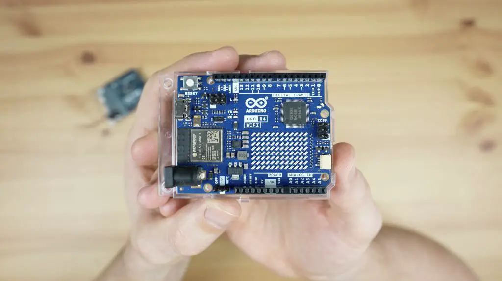
The LED matrix on the WiFi board is really useful for quickly displaying a status or mode, and you can even run some animations and games on it.
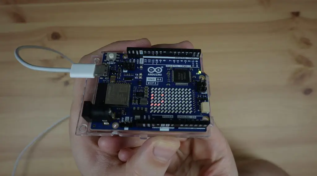
For prototyping, I’m going to use it as a rolling graph of the hot-end temperature so that we can see how it is tracking towards the setpoint.
Recycler Controller Components
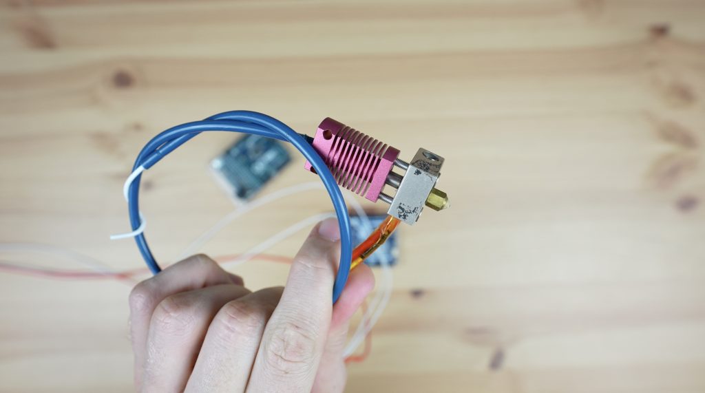
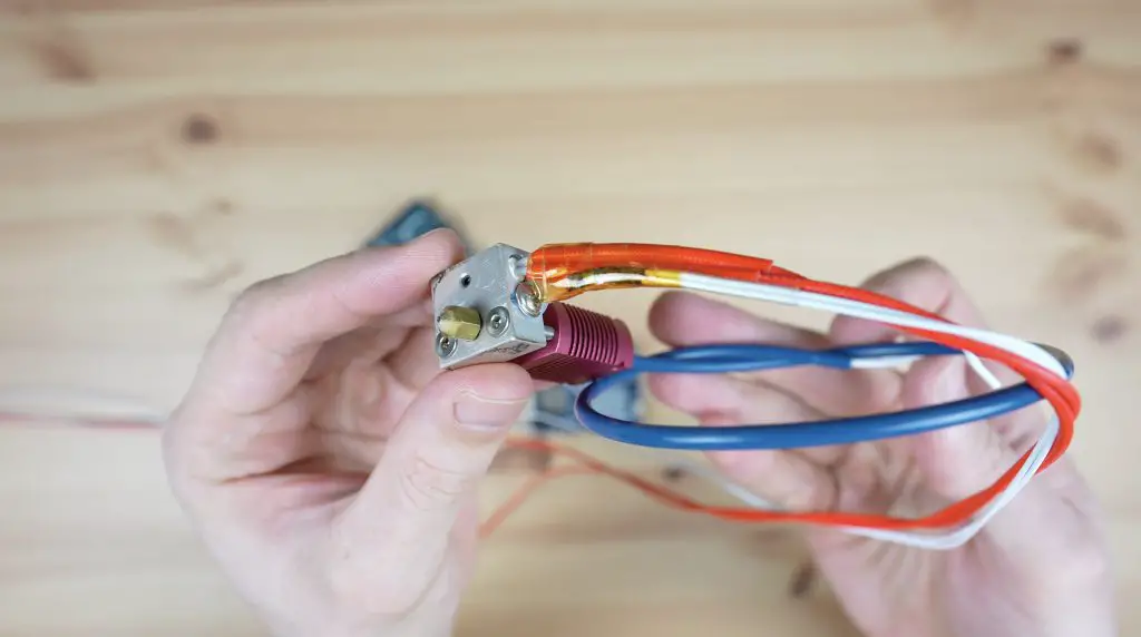
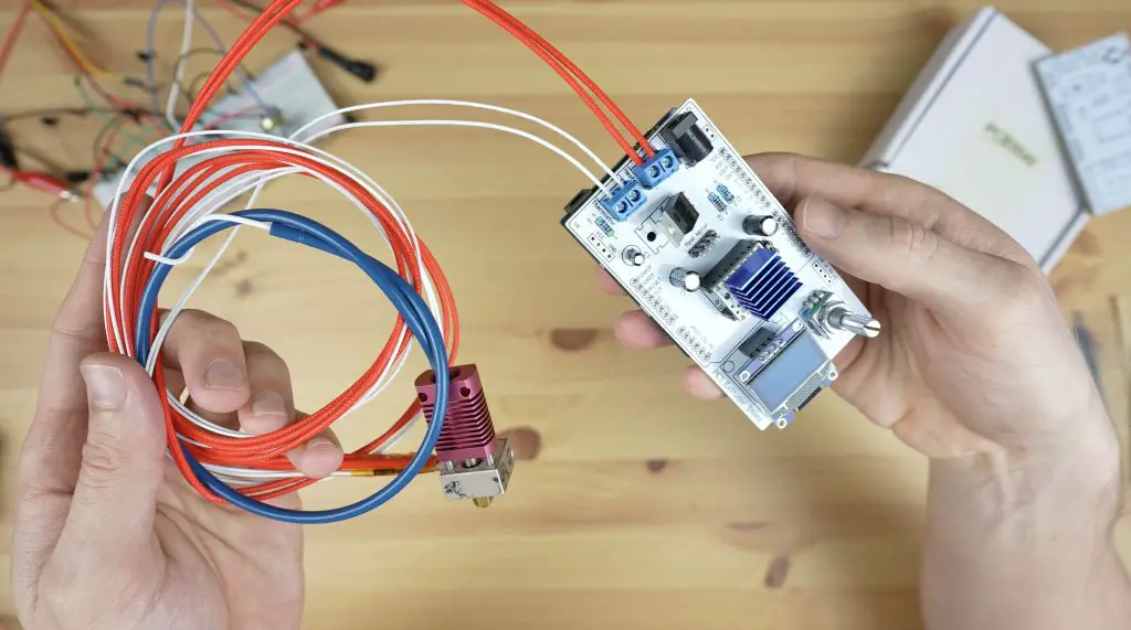
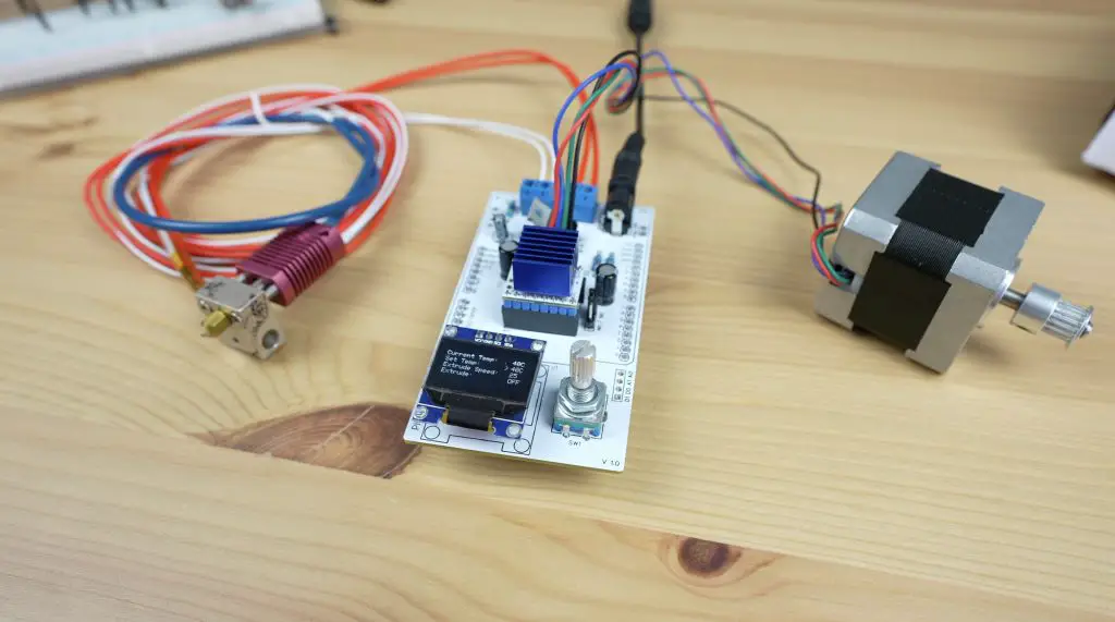
To turn a PET bottle (a standard soda bottle, like Pepsi, Coke or Mountain Dew) into filament, we need a way to melt the plastic. To do that, I’m going to be using a hot-end from an old 3D printer. This one is from an old Creality Ender 3 Pro.
An Arduino obviously can’t pass through enough power to heat the hot end by itself, so for that we’re going to be using an IRFZ44N Power MOSFET.
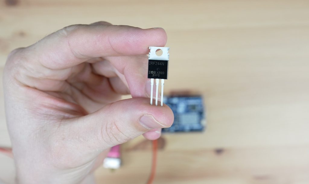
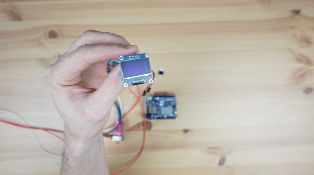
This will take a PWM signal from the Arduino and use it to control the power supplied through to the hot end so that we can maintain a set temperature. I’m also going to add an I2C OLED display to display the exact temperature and allow us to make changes to the temperature and the extruder motor speed.
A temperature sensing element, or thermistor, is also built into the hot end and we’ll use the signal from this to tell the Arduino what the actual temperature of the hot end is so that it knows whether to turn the heating element on or off.
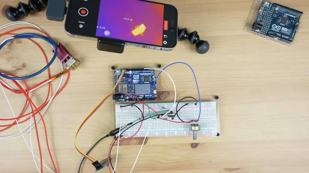
Breadboard Test Circuit
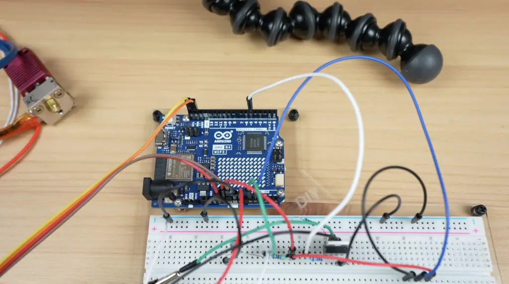
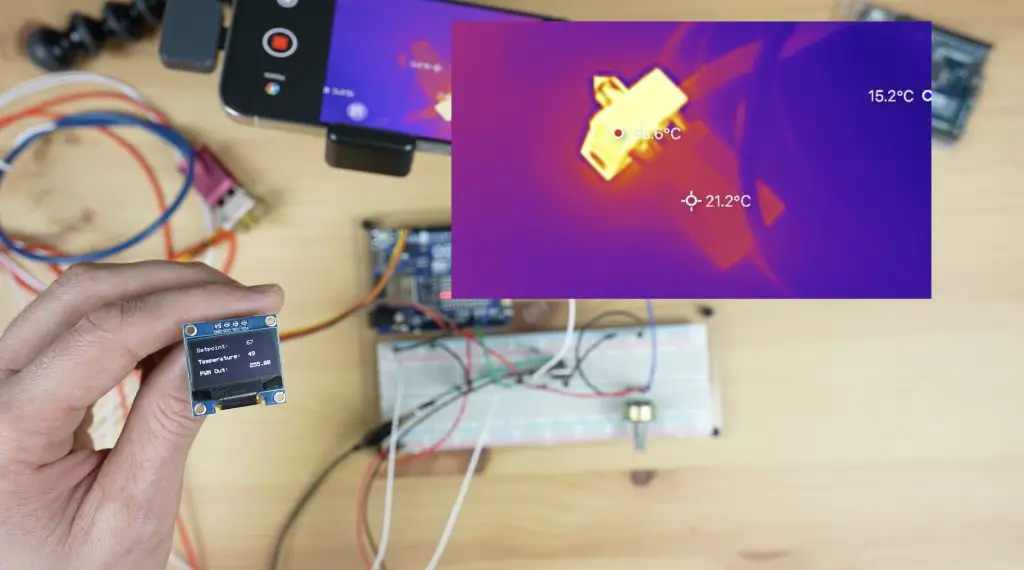
As a starting point, I have made up the basic circuit on a breadboard to test that we’re actually able to control the hot end. I’ve also set up a thermal camera to watch the hot end so that we can visualise it heating up.
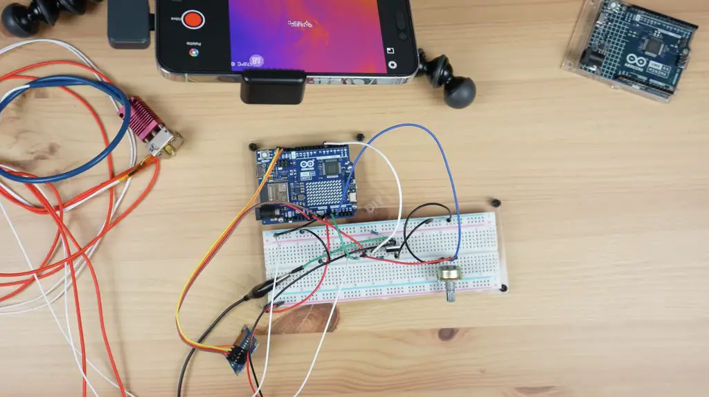
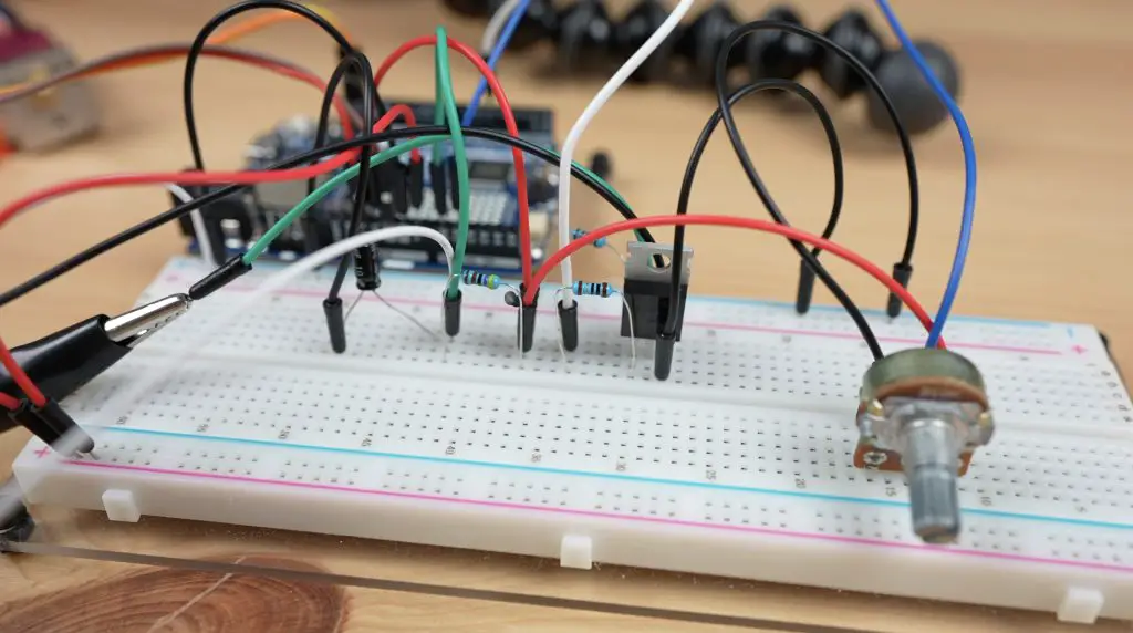
There are two main circuits here, one with the power Mosfet and some resistors to control the heating element and a second with a capacitor and resistor to read in the temperature.
As I said earlier, I’m going to be using the LED matrix on the Arduino as a means of indicating how the temperature of the hot end is tracking towards the setpoint, but I’ve also added an I2C OLED display which will give us an exact temperature readout, the temperature setpoint that we’re working towards and for now an indication of the PWM value being applied to the hot end.
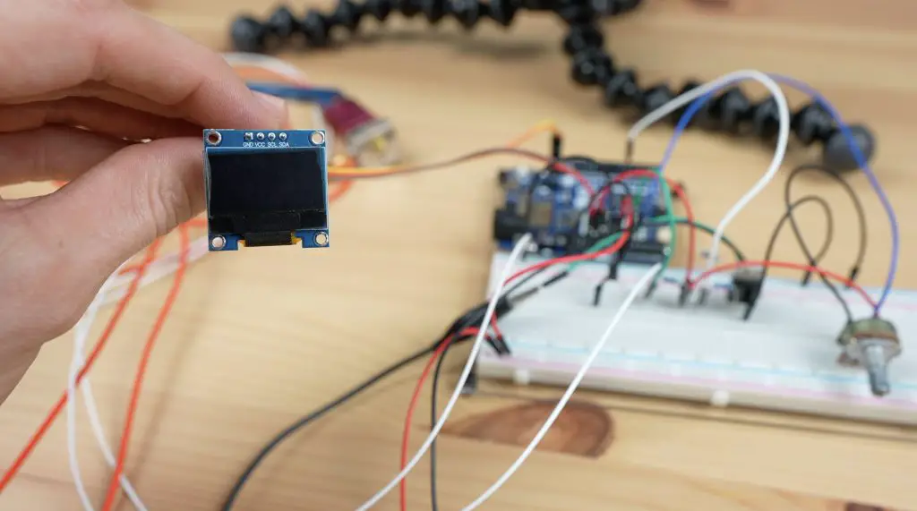
I have also included a potentiometer to adjust the temperature setpoint between an upper and lower limit.
So let’s put power onto the circuit and we’ll hopefully be able to see how it heats up on the thermal camera. After about 30 seconds, we can already see the hot end head heating up.
I’ve used the last column of the LED matrix on the Arduino to indicate the current setpoint that the hot end is heating up to. The graph loops around, increasing as the temperature increases. It is quite slow as I’m only using a supply voltage of 12V where the hot end is rated at 24V.
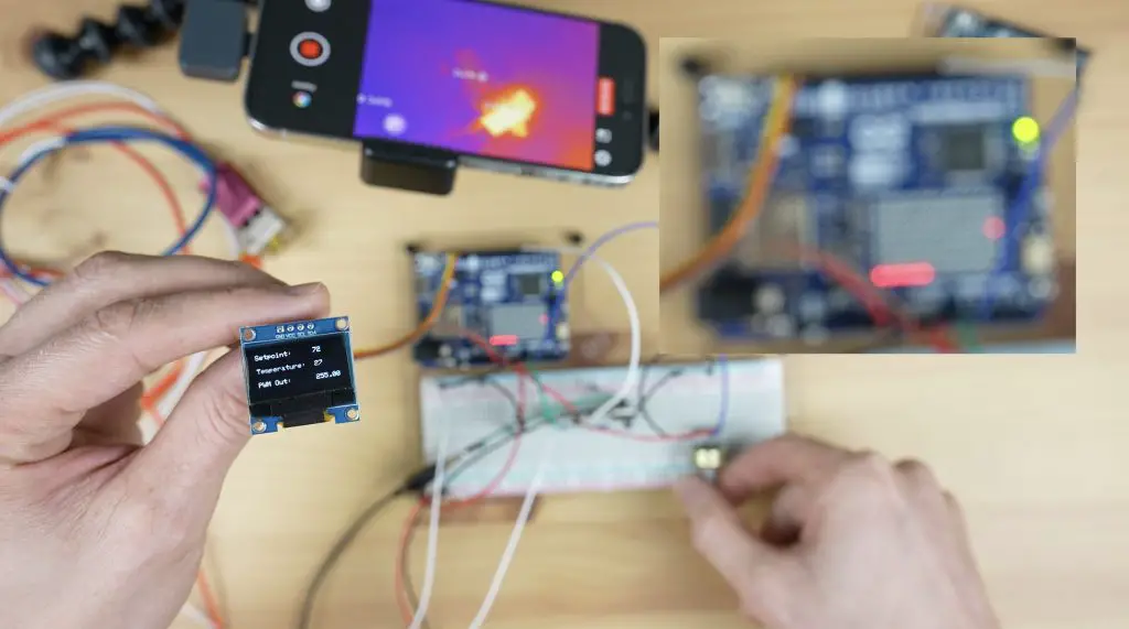
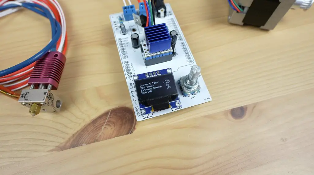
On the OLED display, we can see the temperature setpoint, the current temperature and then the PWM output to the hot end. This stays at the maximum of while heating up and then as the temperature approaches the setpoint, it starts tapering off.
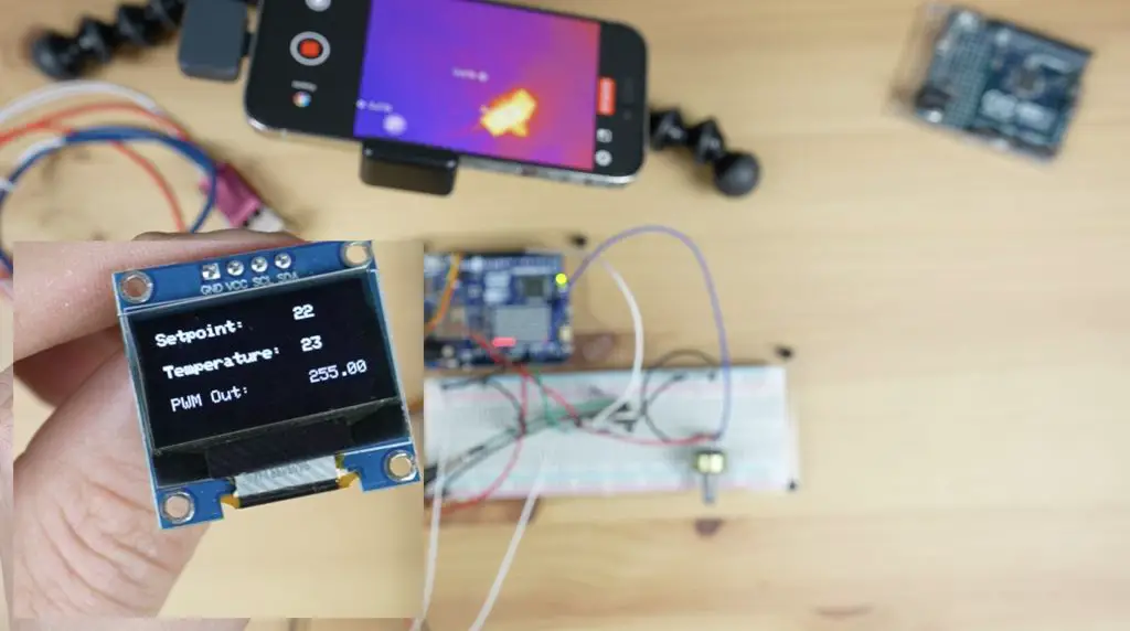
I’m using a PID control function to control the temperature of the hot end, so I’ve tuned the proportional, integral and derivative gain values to provide reasonably good tracking of the setpoint.
After a minute or so, we can now see that the hot end has heated up on the thermal camera.
Now that we’ve got the system working on the breadboard, let’s turn it into something a bit more permanent and reliable for the project.
Designing The Recycler Controller PCB
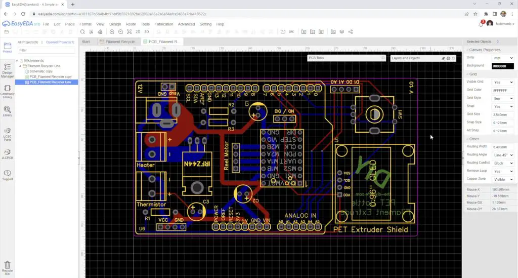
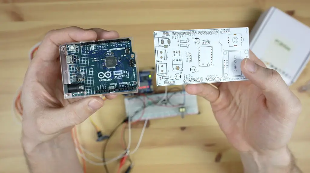
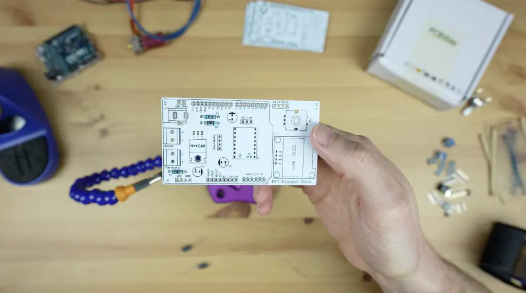
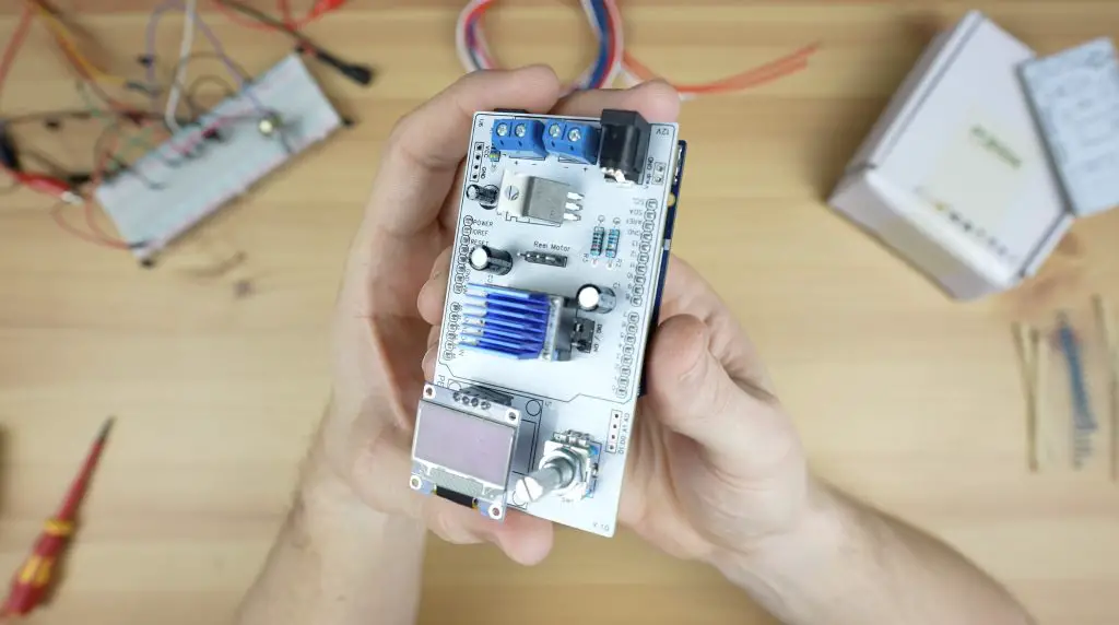
I drew up a schematic and designed a PCB for the recycler controller in the form of a shield to fit on top of the Arduino.
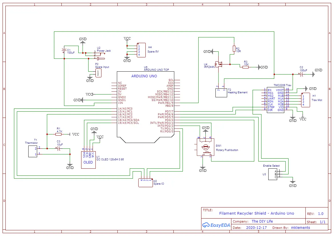
This shield has the heating element circuit, the thermistor circuit and a TMC2208 stepper motor driver to drive the extruder. It’s also got an I2C OLED display and a rotary pushbutton to make changes to the settings.
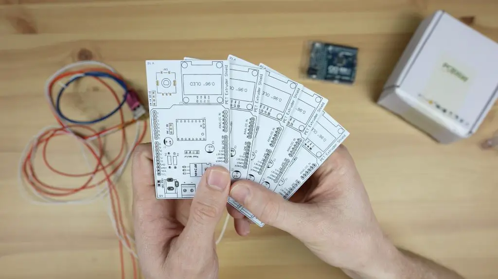
PCBWay then made them up for me. They have a really easy-to-use one-page order form to upload your files to and choose from a range of manufacturing options, with defaults preselected.
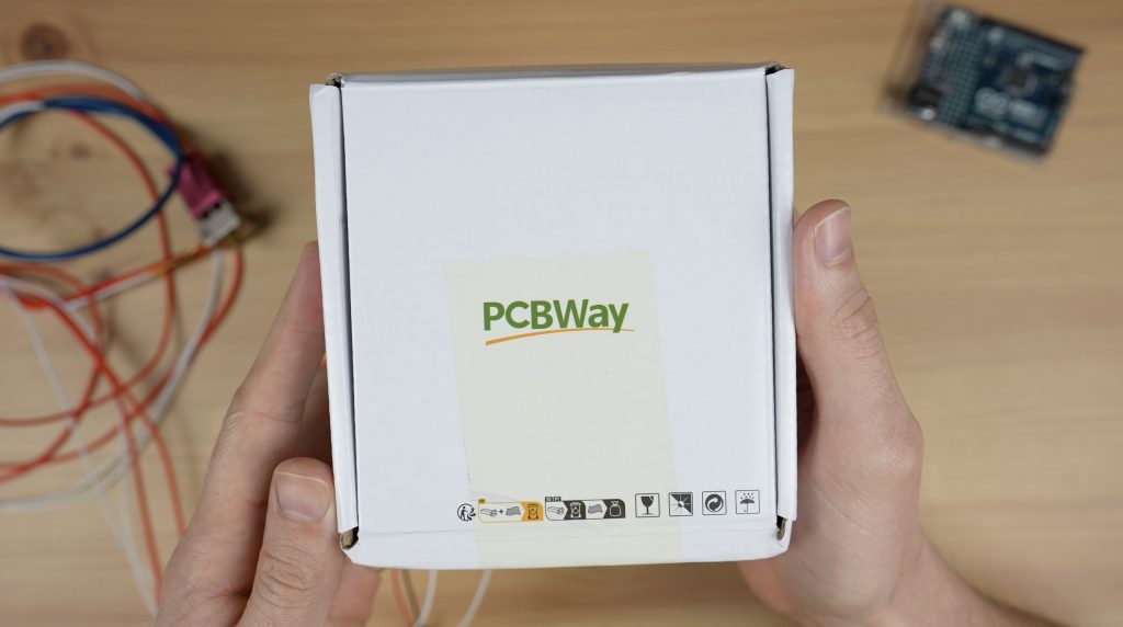
They’ll then make them up for you in 24hrs for just $5 for five, two-layer PCBs. They also offer a range of shipping options to fit your timing and budget. If you haven’t tried making your own PCBs for a project, I’d definitely recommend trying PCBWay out to really take your projects to the next really.
They arrive a few days later, I choose a white PCB with a black silkscreen, just because I haven’t tried this colour scheme before.
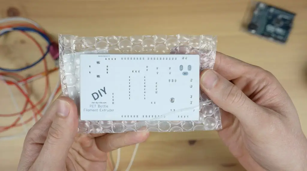
The PCB is designed to interface with the Arduino through some header pins which we’ll add to the underside.
Now we just need to get the components soldered onto the board.
Assembling The Controller PCB
I soldered the components to the board starting with the smaller components and moving on to the larger ones.
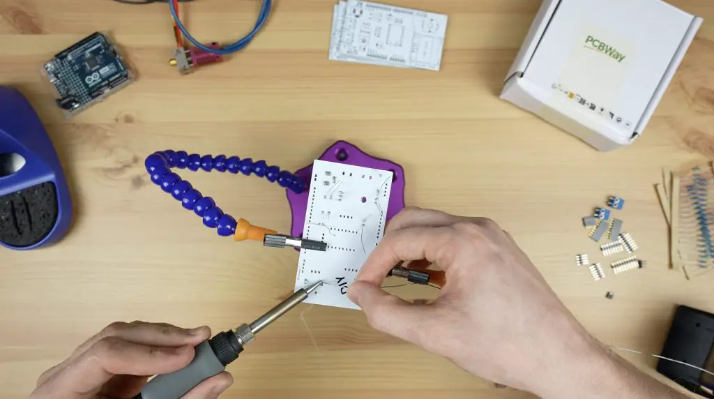
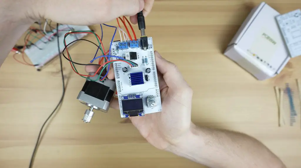
Because this first one is still a prototype board, I’m going to solder some female header strips onto the stepper motor driver and display pads so that I can remove the display and driver to use on the final board. I also soldered the header pins for the Arduino into place while plugged into the Arduino as this keeps them lined up properly.
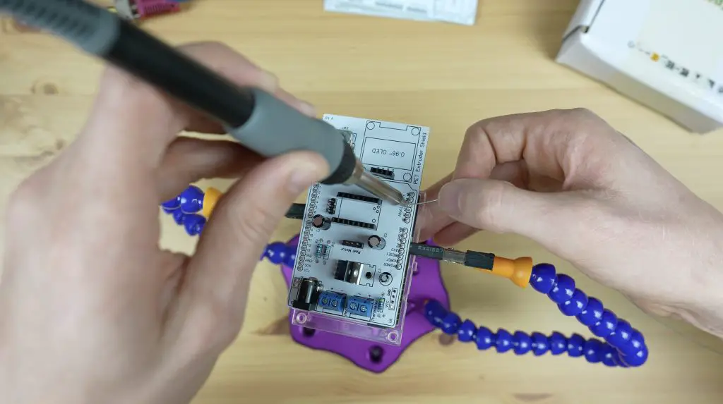
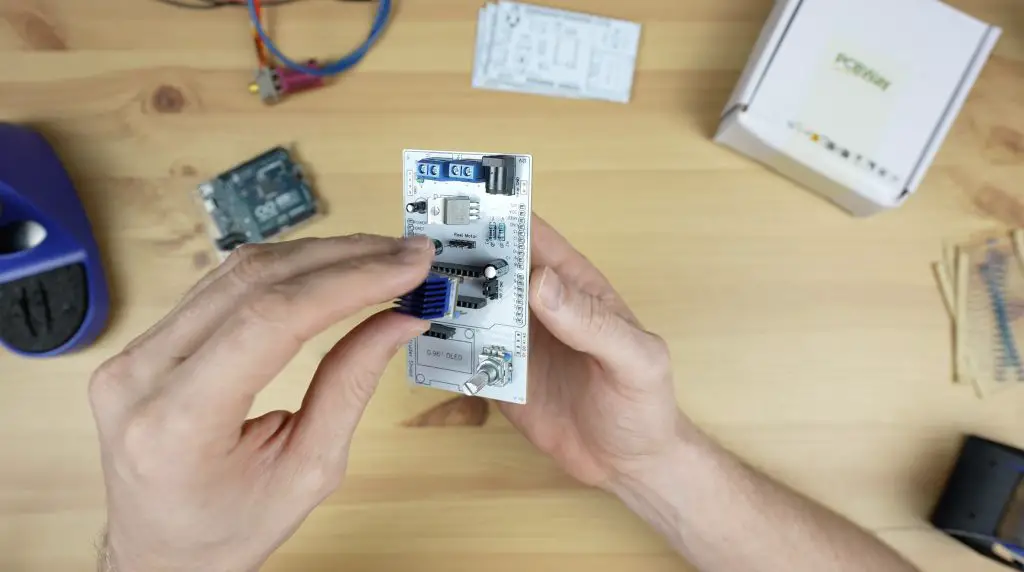
And with the soldering done, it’s time for the moment of truth – to see if my board design and soldering is good. I plugged in the motor driver, jumper and display. I then screwed the heating element and thermistor into the terminals and plugged it in for programming.
Programming The Arduino Uno R4
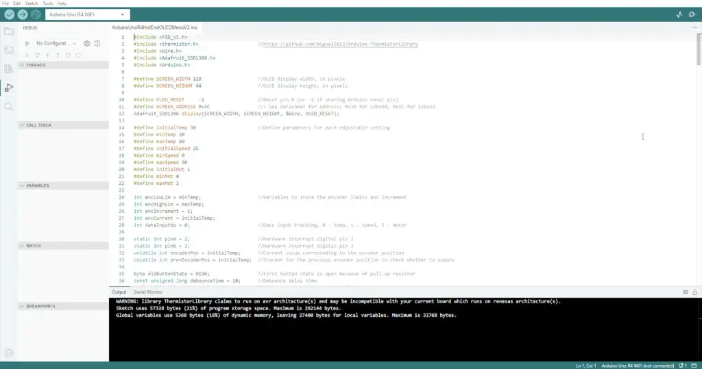
I’ve put the sketch up in my Github repository. It’s just a simple Arduino sketch that runs a PID control loop to control the temperature of the hot end and pulses the stepper motor driver to control the motor. There is also some supporting code to drive the display and manage the input from the rotary push button.
Now let’s get it uploaded to the board and see how it works.
Testing The PET Recycler Controller
The board will run on the USB power from the computer, but won’t drive the motor or heat up the element, we need to add a 12V supply to the shield’s input to power those, so let’s get that plugged in.
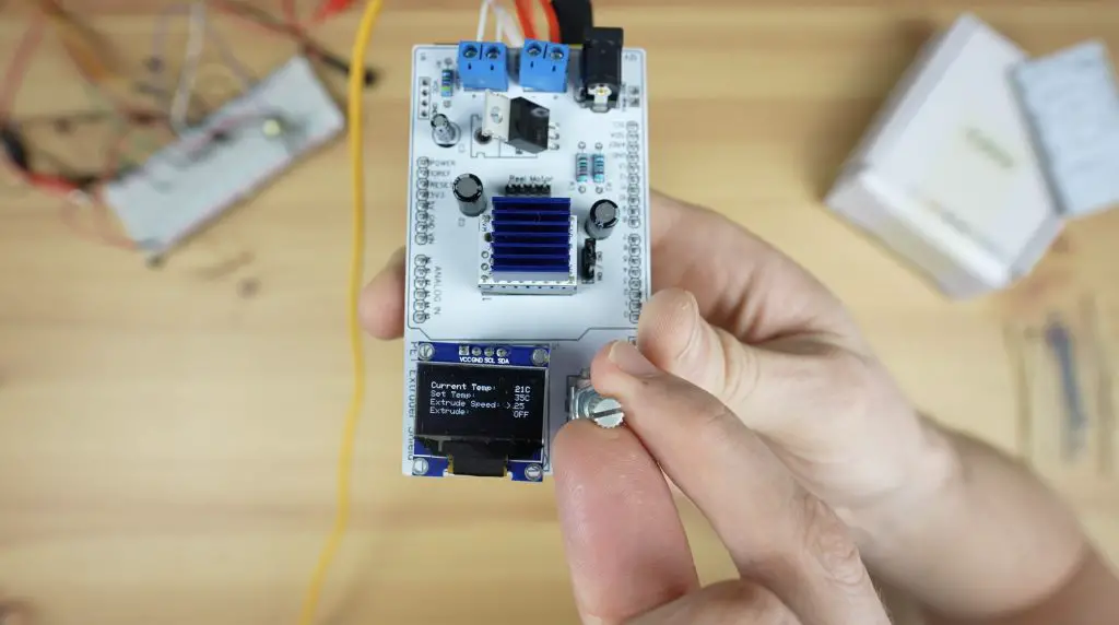
And now the board is running. The actual temperature is shown in the first line and we can adjust the temperature setpoint using the rotary pushbutton.
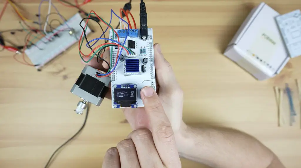
The line below allows us to change the motor speed on the extruder and the bottom line lets us turn the extruder motor on, either running forward or in reverse. Once again I’m really impressed with how quiet the TMC2208 stepper motor driver is.
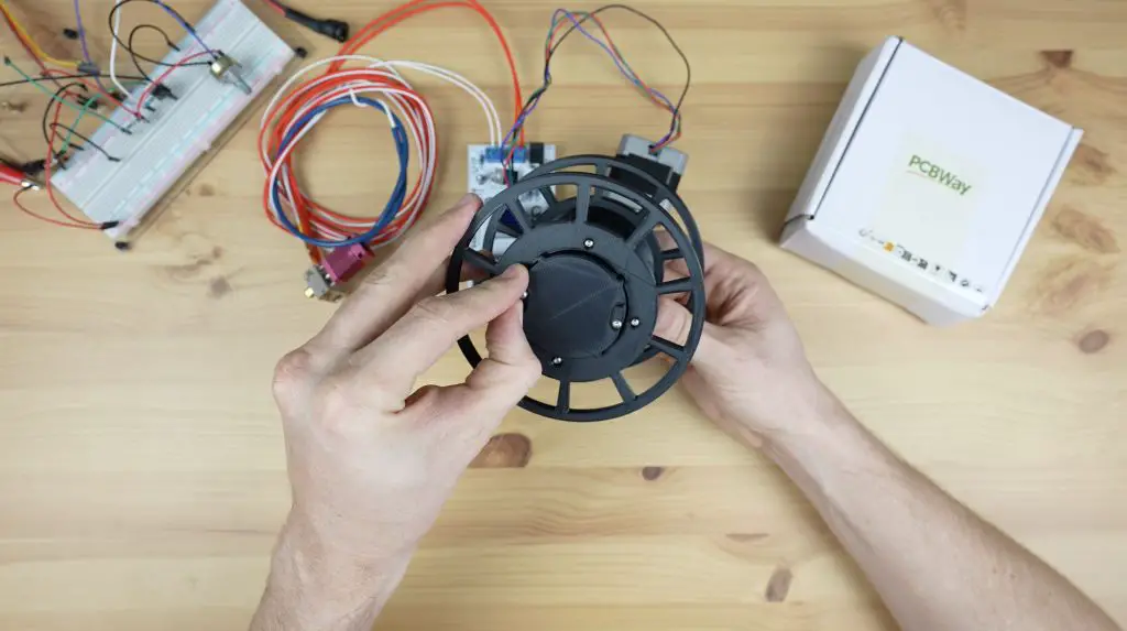
I’m really happy with how this has come out. For the final version, I might try and make the PCB a bit more compact, perhaps using a smaller form factor Arduino like the Pro Mini. For now, this will be great to get started building the mechanical parts for the PET bottle recycler.
If you’re interested in seeing the project progress, be sure to subscribe to my newsletter or YouTube channel. I’ve got a geared stepper motor and pulleys coming to try out and some cool ideas for a removable spool on the recycler that I can easily move across to my printer when the filament has been extruded.
I’m also really interested to see how a recycled PET version of my 3D printable Raspberry Pi case turns out. I have now completed the PET Bottle Recycler, you can find Part 2 here.
Let me know in the comments if you’ve got any suggestions for improvements that I can make to the final version which I’ll use on the recycler.
Hi Michael,
it’s a very interesting project but I’m missing some information. Do you share the Gerbers or KiCAD/Eagle files) for your PCB? On PCBWAY I found no possibility to order customer made files.
Best regards,
Hans
Wie betaald de schade? (Hans) Ik kan jou wel een tikkie neem ik aan?
polska gurom
I I have a question regarding the code. I have Arduino mega, a4988 stepper motor drive with heatsink, a LCD 12864 display. will the code be slightly the same. how will the code change.
What is the resisters number and capacitor. And I have some items. I have an Arduino mega 2560. the cnc shield, then a lcd 12864 display. can I reconfigure the program in the direction.
Hey, this is a great work.
Can I do this project with Arduino uno r3 & without pcb?
I have a few questions what are the capacitor sizes and the resister sizes. The video is great but for someone that isn’t too familiar with electronics I could use a little help. With figuring out the capacitors and resisters needed. The video doesn’t state or list the parts that are soldered on the board. Any help would be greatly appreciated. This is for the pet Radin recycler motor controller.
Thanks for the help
This is super cool! I love how you’re using the Arduino Uno R4 WiFi to build a PET bottle recycler controller. The LED matrix on the WiFi version sounds like a fun addition. Have you thought about adding some sensors to monitor the recycling process? I once tried a DIY project and sensors made it even more interesting.
Buongiorno Michael mi chiamo Francesco sto cercando di replicare questo interessante progetto, è quasi terminato. l’unico incoveniente è che quando carico lo sketch su arduino minima R4 mi dà errore “Compilation error:’thermistor’ does not name a type;did you mean?register’?
ho trovato l’errore, il firmware funziona solo su arduini uno R3 i pcb sono perfetti ora passo all’assemblaggio della macchina
The firmware can also be easily uses with the Arduino Pro Mini.