I was walking through the hardware store the other day and I walked past an energy meter which clips onto your home’s electricity mains and then provides you with information on your power consumption and cost estimates for the month. I thought it looked really cool until I saw the price, it was almost five times what I thought it would be! So I decided to try and build my own and Arduino was the perfect platform for it.
I had a look around online at what others had done but they all seemed to be a bit over complicated for a simple home application. Sure, for perfectly accurate measurements you need to monitor both the supply voltage and current but for simple household monitoring which gives estimates cost to the closest few cents, why not keep things simple.
So this meter measures the supply current to your home through a CT (current transformer) and then does a couple of calculations to give you your current, power, maximum power and kilowatt hours consumed. Its also really easy to add your local tariff and display the cost of electricity used to date.
Update: Follow this guide is if you are wanting to build a 3 phase energy meter.
This project assumes you know the basics of Arduino programming, otherwise read our article on getting started with Arduino, and that you know how to connect an LCD screen to an Arduino.
What You Will Need For A Home Energy Meter
- An Arduino (Uno used in this guide) – Buy Here
- LCD Shield (Or LCD Screen – how to connect an LCD screen) – Buy Here
- CT – Talema AC1030 (See below for different options and purchase links)
- 56Ω Burden Resistor – Buy Here
- 10µF Capacitor – Buy Here
- 2 x 100K Divider Resistors – Buy Here
How To Make The Energy Meter
First you need to start by assembling the components onto the CT or onto your breadboard in order to create your current sensor which produces a signal which your Arduino can understand. An Arduino only has analogue voltage inputs which measure 0-5V DC, so you need to convert the current output from the CT into a voltage reference and then scale the voltage reference into a 0-5V range.
Assemble the Components
If you are going to be installing your power meter somewhere permanently then you may want to solder the resistors and capacitor directly onto the CT so that they cannot come loose. If you are simply trying this project for fun then a breadboard is perfect.
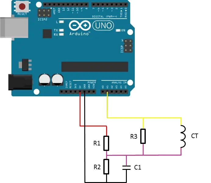
The basic circuit for the connection of the CT to the Arduino is shown in the diagram below:
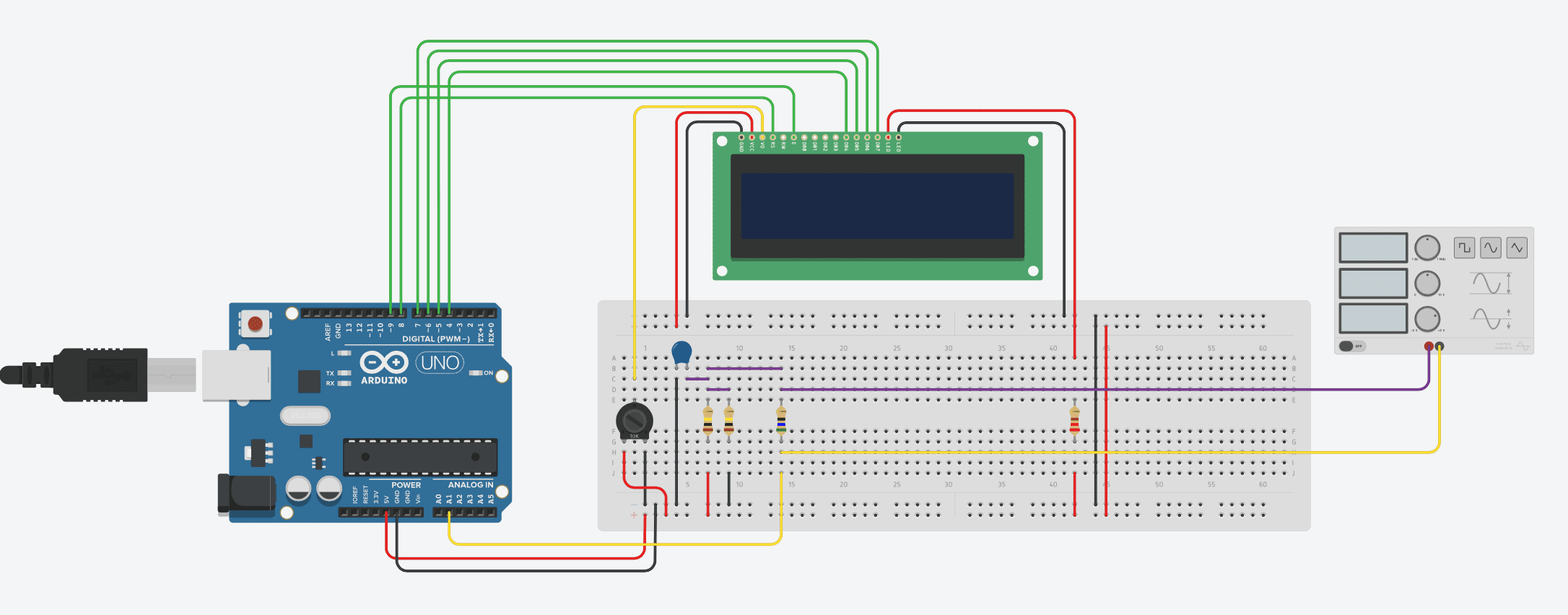
A breadboard circuit layout is shown below. Please note that TinkerCAD doesn’t support a current transformer. A signal generator has therefore been used to generate an example signal:
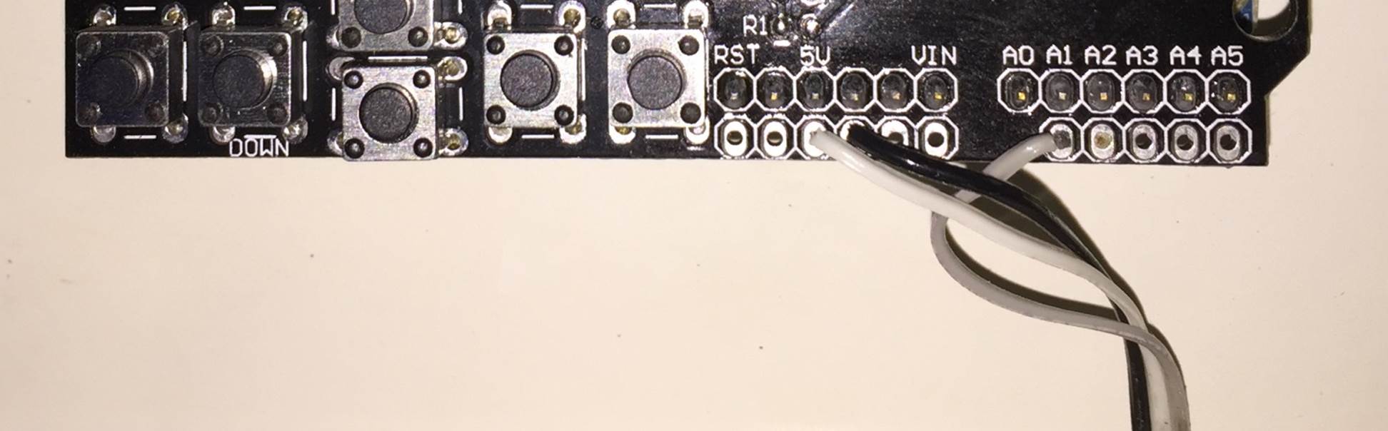
The LCD screen shield already picks up on the analogue inputs but only A0 is used by the shield. Simply solder the three leads from your current sensor onto the pin headers on the shield and use A1 as your sensor input as shown below.
Once you have connected all of your components, you need to connect your sensor onto what you want to monitor. If you are wanting to monitor a couple of appliances then you should connect the CT onto the input lead of a multi-plug, anything you plug into the multi-plug with then be counted.
Alternately, you can connect the CT directly onto your home’s mains supply and monitor the whole houses usage as has been done here. Either way, you need to put the CT around one of the supply cables, preferably the red “live” cable. Be sure to only put it around 1 as it will not work if it is around both and it can’t be connected around the earth wire (yellow, green stripped wire) as energy is not drawn through this wire. If you are connecting it to your mains, connect it to one of the output wires after the main breaker as shown below.
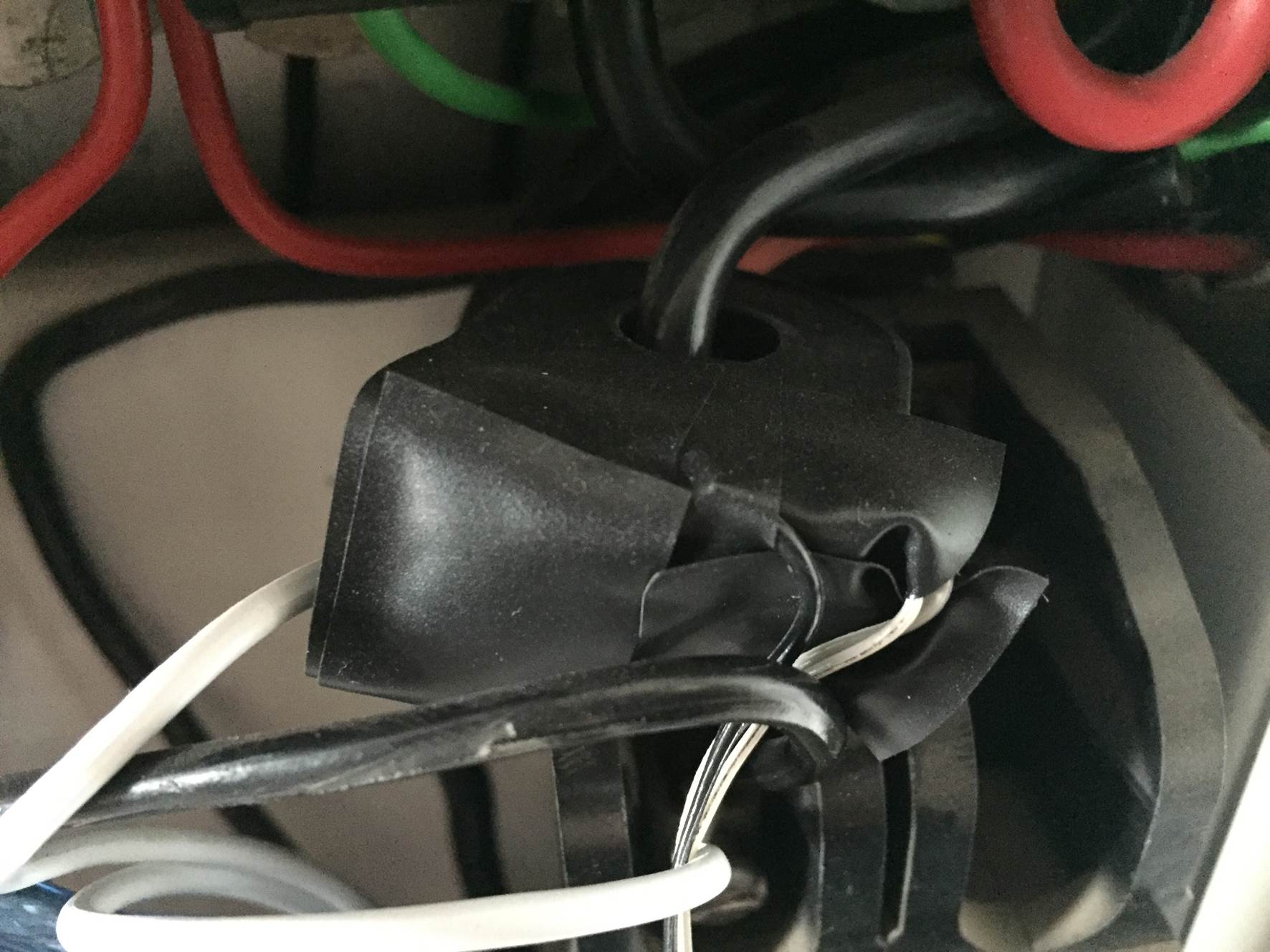
NB – Be careful when connecting the power meter to you homes mains and make sure that the power to your board is switched off before doing anything in the mains box. Do not remove any wires or remove any screws before checking with your local authority, you may require a certified electrician to install the CT for you.
Choosing Different Components
There are essentially four components which need to be chosen or correctly sized for you energy meter.
Choosing A Current Transformer
The first is the CT or current transformer. The one used here is the Talema AC1030 which can sense 30A nominal and 75A maximum current. At 220VAC, it can theoretically sense up to 16.5kW for short periods of time but it is sized to continuously sense 6.6kW which is suitable for a small household. To calculate how many amps yours needs to sense, take the maximum continuous power your are expecting to sense and divide that by your voltage (usually 110V or 220V depending on your country).
Sizing The Burden Resistor
Next you need to size your burden resistor R3, this converts your CT current into a voltage reference. Start by dividing your primary current (the maximum as used above) by your CT’s turns ratio (available on the data sheet). This should be around 500-5000 to 1. This article worked on 42A with a turns ratio 0f 1000:1 giving a secondary current of 0.042A or 42mA. Your analogue reference voltage to the Arduino is 2.5V so to determine the resistance you use R=V/I – R=2.5/0.042=59.5Ω. The closest standard resistor value is 56Ω, so this was used.
Here are some options on different CTs and their ideal burden resistors (in standard sizes):
- Murata 56050C – 10A – 50:1 – 13Ω
- Talema AS-103 – 15A – 300:1 – 51Ω
- Talema AC-1020 – 20A – 1000:1 – 130Ω
- Alttec L01-6215 – 30A – 1000:1 – 82Ω
- Alttec L01-6216 – 40A – 1000:1 – 62Ω
- Talema ACX-1050 – 50A – 2500:1 – 130Ω
- Alttec L01-6218 – 60A – 1000:1 – 43Ω
- Talema AC-1060 – 60A – 1000:1 – 43Ω
- Alttec L01-6219 – 75A – 1000:1 – 33Ω
- Alttec L01-6221 – 150A – 1000:1 – 18Ω
- CTYRZCH SCT-013-000 – 100A – Built In Burden Resistor – Buy Here
- TOOGOO SCT-013-000 – 100A – Buy Here
The capacitor used is 10µF which should be sufficient for most CT ranges for household applications.
Finally you need two dividing resistors to get the 2.5V reference voltage from the Arduino. They must be the same value, so R1=R2 and we don’t need much current so this articles uses two 100K resistors.
Upload the Sketch
Now you can upload your sketch onto your Arduino, if you haven’t uploaded a sketch before then follow this guide on getting started.
Update – The code has since been modified to make use of the millis() function, see end of section for updated code.
//Michael Klements
//The DIY Life
//27 October 2014

#include <LiquidCrystal.h>

int currentPin = 1;              //Assign CT input to pin 1
double kilos = 0;
int peakPower = 0;
LiquidCrystal lcd(8, 9, 4, 5, 6, 7);  //Assign LCD screen pins, as per LCD shield requirements

void setup()
{
  lcd.begin(16,2);              // columns, rows.  use 16,2 for a 16x2 LCD, etc.
  lcd.clear();
  lcd.setCursor(0,0);           // set cursor to column 0, row 0 (the first row)
  lcd.print("Running");
}

void loop()
{
  int current = 0;
  int maxCurrent = 0;
  int minCurrent = 1000;
  for (int i=0 ; i<=200 ; i++)  //Monitors and logs the current input for 200 cycles to determine max and min current
  {
    current = analogRead(currentPin);    //Reads current input and records maximum and minimum current
    if(current >= maxCurrent)
      maxCurrent = current;
    else if(current <= minCurrent)
      minCurrent = current;
  }
  if (maxCurrent <= 517)
  {
    maxCurrent = 516;
  }
  double RMSCurrent = ((maxCurrent - 516)*0.707)/11.8337;    //Calculates RMS current based on maximum value
  int RMSPower = 220*RMSCurrent;    //Calculates RMS Power Assuming Voltage 220VAC, change to 110VAC accordingly
  if (RMSPower > peakPower)
  {
    peakPower = RMSPower;
  }
  kilos = kilos + (RMSPower * (2.05/60/60/1000));    //Calculate kilowatt hours used
  delay (2000);
  lcd.clear();
  lcd.setCursor(0,0);           // Displays all current data
  lcd.print(RMSCurrent);
  lcd.print("A");
  lcd.setCursor(10,0);
  lcd.print(RMSPower);
  lcd.print("W");
  lcd.setCursor(0,1);
  lcd.print(kilos);
  lcd.print("kWh");
  lcd.setCursor(10,1);
  lcd.print(peakPower);
  lcd.print("W");
}
Here is the link to download the Meter code.
Because your setup, CT , resistors and input voltage may be different, there is a scaling factor in the sketch which you will need to change before you will get accurate results, see below for calibration. If your LCD is connected to the same pins as used here and your CT is connected to the same input pin, you should at least get the screen populated with some figures although these will most likely be incorrect and some may be negative.
If you don’t want to use or don’t have an LCD screen, you can also modify the sketch to output to the Arduino IDE’s serial window as shown below.
//Michael Klements
//The DIY Life
//27 October 2014

int currentPin = 1;              //Assign CT input to pin 1
double kilos = 0;
int peakPower = 0;

void setup()
{
  Serial.begin(9600);            //Start serial communication
  Serial.println("Running");
}

void loop()
{
  int current = 0;
  int maxCurrent = 0;
  int minCurrent = 1000;
  for (int i=0 ; i<=200 ; i++)  //Monitors and logs the current input for 200 cycles to determine max and min current
  {
    current = analogRead(currentPin);    //Reads current input and records maximum and minimum current
    if(current >= maxCurrent)
      maxCurrent = current;
    else if(current <= minCurrent)
      minCurrent = current;
  }
  if (maxCurrent <= 517)
  {
    maxCurrent = 516;
  }
  double RMSCurrent = ((maxCurrent - 516)*0.707)/11.8337;    //Calculates RMS current based on maximum value
  int RMSPower = 220*RMSCurrent;    //Calculates RMS Power Assuming Voltage 220VAC, change to 110VAC accordingly
  if (RMSPower > peakPower)
  {
    peakPower = RMSPower;
  }
  kilos = kilos + (RMSPower * (2.05/60/60/1000));    //Calculate kilowatt hours used
  delay (2000);
  Serial.print(RMSCurrent);
  Serial.println("A");
  Serial.print(RMSPower);
  Serial.println("W");
  Serial.print(kilos);
  Serial.println("kWh");
  Serial.print(peakPower);
  Serial.println("W");
}
Here is the link to download the Meter Serial Output code.
Code Update
The original Energy Meter code made use of a fixed time period for calculating the kilowatt hours consumed, this was based on a 2050ms cycle time and was fairly accurate.
The code has since been modified to make use of the built in millis() function which calculates the exact cycle time for each cycle in order to improve the accuracy. It only makes around a half a percent improvement in the accuracy of the calculation but its the better way to do it.
Here is the improved code:
//Michael Klements
//The DIY Life
//26 February 2017

#include <LiquidCrystal.h>

int currentPin = 1;              //Assign CT input to pin 1
double kilos = 0;
int peakPower = 0;
unsigned long startMillis;
unsigned long endMillis;
LiquidCrystal lcd(8, 9, 4, 5, 6, 7);  //Assign LCD screen pins, as per LCD shield requirements

void setup()
{
  lcd.begin(16,2);              // columns, rows.  use 16,2 for a 16x2 LCD, etc.
  lcd.clear();
  lcd.setCursor(0,0);           // set cursor to column 0, row 0 (the first row)
  lcd.print("Arduino");
  lcd.setCursor(0,1);           // set cursor to column 0, row 1 (the second row)
  lcd.print("Energy Meter");
  startMillis = millis();
}

void loop()
{
  int current = 0;
  int maxCurrent = 0;
  int minCurrent = 1000;
  for (int i=0 ; i<=200 ; i++)  //Monitors and logs the current input for 200 cycles to determine max and min current
  {
    current = analogRead(currentPin);    //Reads current input and records maximum and minimum current
    if(current >= maxCurrent)
      maxCurrent = current;
    else if(current <= minCurrent)
      minCurrent = current;
  }
  if (maxCurrent <= 517)
  {
    maxCurrent = 516;
  }
  double RMSCurrent = ((maxCurrent - 516)*0.707)/11.8337;    //Calculates RMS current based on maximum value
  int RMSPower = 220*RMSCurrent;    //Calculates RMS Power Assuming Voltage 220VAC, change to 110VAC accordingly
  if (RMSPower > peakPower)
  {
    peakPower = RMSPower;
  }
  endMillis = millis();
  unsigned long time = endMillis - startMillis;
  kilos = kilos + ((double)RMSPower * ((double)time/60/60/1000000));    //Calculate kilowatt hours used
  startMillis = millis();
  delay (2000);
  lcd.clear();
  lcd.setCursor(0,0);           // Displays all current data
  lcd.print(RMSCurrent);
  lcd.print("A");
  lcd.setCursor(10,0);
  lcd.print(RMSPower);
  lcd.print("W");
  lcd.setCursor(0,1);
  lcd.print(kilos);
  lcd.print("kWh");
  lcd.setCursor(10,1);
  lcd.print(peakPower);
  lcd.print("W");
}
Here is the link to download the updated Millis Meter code.
For those of you who have read that the millis() function goes into overflow after about 49 days, the code deals with the rollover automatically by making use of the unsigned long variable. For example, if the overflow happens at 10000, the start millis was 9987 and the end millis was 2031, the difference would be 2031-9987=-7956 but the value can’t be negative as it is unsigned so it becomes -7956+10000=2044 which is the correct duration.
Calibrate the Current Reading
As mentioned above, because your setup, CT , resistors and input voltage may be different, there is a scaling factor in the sketch which you will need to change before you will get accurate results.
To calibrate your energy meter, your need to be sure that the current that your meter says is being drawn is what you expect is actually being drawn. In order to do this accurately, you need to find a calibrated load. These are not easy to come by in a normal household so you will need to find something which uses an established and consistent amount of power. I used a couple of incandescent light bulbs and spot lights, these come in a range of sizes and their consumption is fairly close to what is stated on the label, ie a 100W light bulb uses very close to 100W of real power as it is almost entirely a purely resistive load.
Plug in a small light bulb (100W or so) and see what load is displayed. You will now need to adjust the scaling factor uses in the calculation line:
double RMSCurrent = ((maxCurrent – 516)*0.707)/11.8337
In this case it was 11.8337, it may be higher or lower depending on your application. Either use linear scaling to calculate this figure or, if you’re not good with math, play around with different values until the load you have plugged in is shown on the energy meter’s screen.
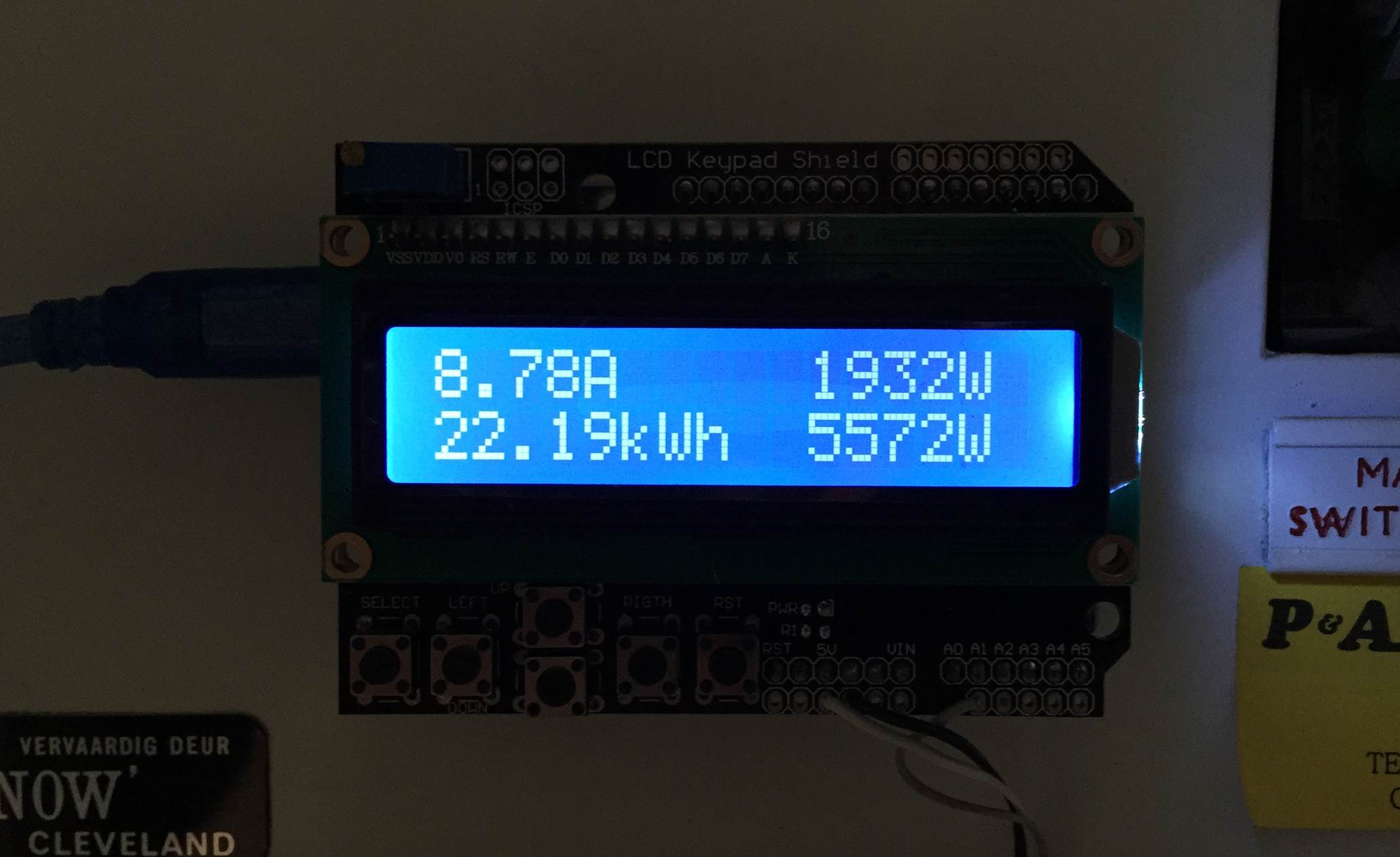
Once you have your energy meter calibrated, you reset it and leave it to do its job. Below are two images of it in use, both with a low power input and a high power input.
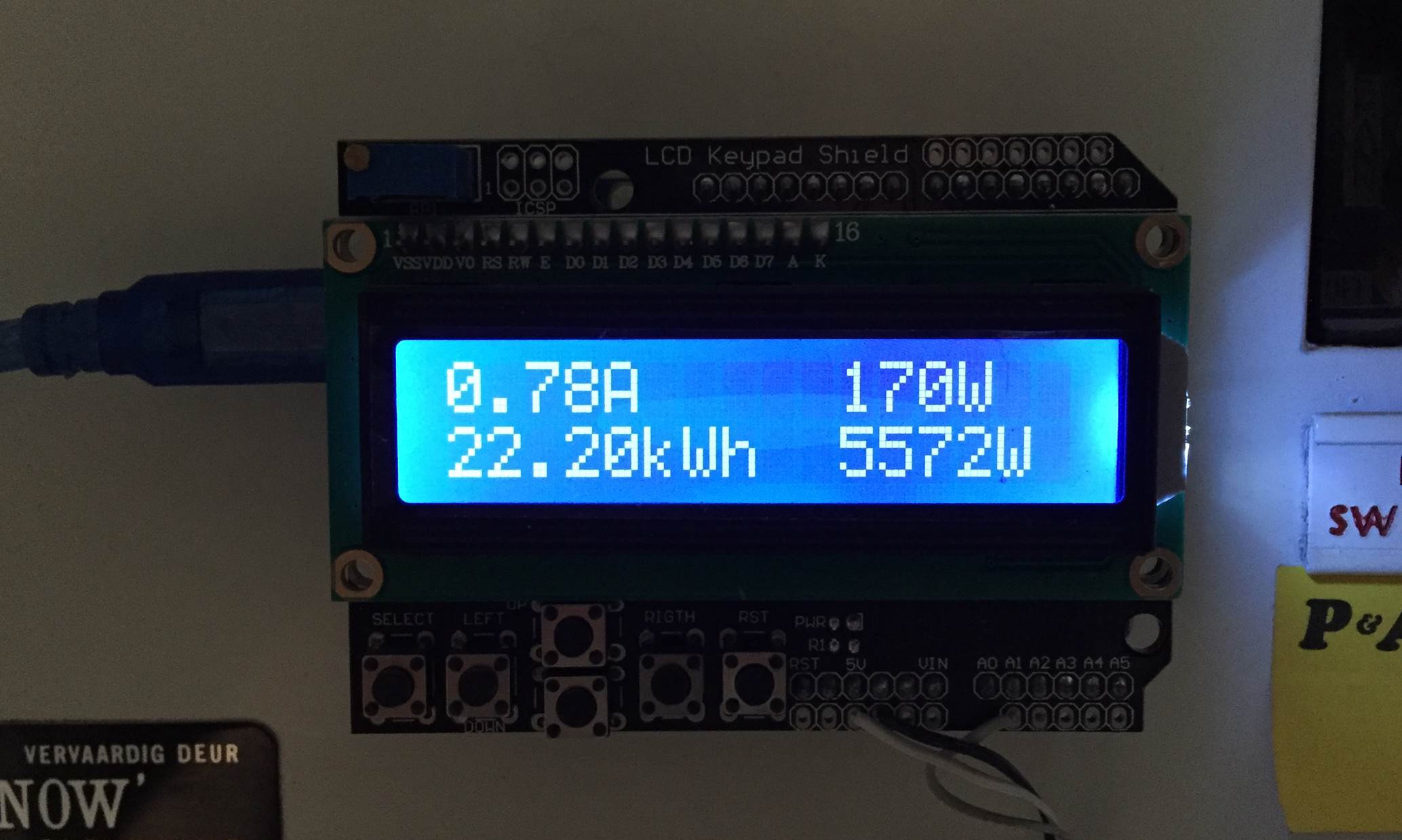
The first number displayed is the instantaneous current followed by the instantaneous power. On the bottom line, the kilowatt hours used since reset and then the maximum recorded power since reset.
And a video of startup:
Video Guide
How did this project go for you? What have you used it to monitor? Let us know in the comments section below, we may even put some of your work into our article to help others. Also feel free to post any questions or queries you may have, if you are asking, chances are someone else is wondering as well.
Great article!!! You have writing talent.
Where did you buy your Current Sense Transformers (CT)?
Hi Dani,
Thank you. I picked up the CT from a local electronics supplier. They are available on eBay, probably Radio Shack as well. There are a number of online suppliers around.
hello sir how can i display the voltage and cost in the display sir can u give me the code sir and how to do sir
Good work! Thanks.
I tried this but extended it with 2 extra CTs, one for all three phases. I do not know why, but all three give me exact same values and they do not change a bit. So, I figure this has to do with the “if (maxCurrent <= 517) maxCurrent=516". Were does this number 516 come from? (Surely a dum question to you… 🙂 ).
Best regards Richard
Hi Richard,
Great to hear you’ve tried this out on a three phase installation.
You essentially need to triplicate lines 22 to 42, or run a loop three times (one for each phase). Make sure that you change line 27 where you read the analogue input to currentPin1, currentPin2 and currentPin3 so that the Arduino is reading inputs from the three different CT’s. Unless your code is overwriting variables incorrectly you should always land up with different figures for each phase this way.
To answer your question, we are only looking at the top half of each phases sine wave. The Arduino’s analogue map function maps from 0 to 1024. 512 is therefore the middle/zero line of the sine wave in an ideal environment, in my case 516 was the “calibrated” zero line. The line of code you mention is simply throwing out the negative half of the sine wave so it is unlikely to be giving you problems.
If you still run into problems, email your code through to me: admin(at)the-diy-life.com and I’ll have a look at it.
Hope this helps!
Best Regards
Hi Richard,
I have just published a guide on how to make a 3 phase energy meter – go have a look at it https://www.the-diy-life.com/simple-3-phase-arduino-energy-meter/
Hope it helps!
Greetings,
Thank you for your article. It has been very helpful to me.
I have a couple of novice questions.
I had started building an energy monitor based on what I had read on openenergymonitor.org.
I am using an Arduino Uno Rev 2, and four SCT-013-030 CTs. My main goal is to calculate kw used by my heat pump (Condenser, AHU and heat strips) and my hot water tank.
I stumbled onto your project and I have been using your Arduino sketch, because you have the kwh calculated.
I have yet to do calibration on the kwh, but I did adjust to get the current fairly accurate.
I can’t figure out what the 2.05 is on line 43. Can you explain to me how you are coming up with kwh?
How are you calculating kw measured over time?
Thanks,
Mike
Hi Mike,
Great, thank you. It’s always good to see people are trying this project out. It sounds like you are doing quite a nice adaptation by monitoring multiple appliances/devices.
To calculate the kilowatt hours, you multiply your amp reading by the supply voltage and then by the time period converted into hours, that will be watt hours and then divide by 1000 to get kilowatt hours.
The line in the code you are referring to is doing the unit conversions, from seconds to hours and into kilowatts, as described above and the 2.05 is the time period (in seconds) I am referring to. The delay in the code is 2000 milliseconds and the loop through the code takes the Arduino about 50 milliseconds to run through so the time period is 2050 milliseconds or 2.05 seconds.
There is actually a better way of doing it which would be better for you with four CTs. Using the millis function, record the start millis and finish millis, calculate the difference and that is your time period. It’s more accurate but I just haven’t had the time to change it in the code.
Hope this helps, let us know how it goes!
Firstly id like to say Great write up
Been looking for someone to explain as good as you did for a few months now 🙂
Hi just a silly question
what voltage must the 10uf capasitor be?
Thanks
Hi Marius,
Thank you, happy to hear we could help. The capacitor only sees around 2.5V so you can use a small 10V capacitor.
Best regards.
Hi
I have managed to put it together using a 33ohm burden resistor because i have the sct-013-010 current transformer and saw that i must use a 33 ohm burden dont know if this is correct
I also used the R1 and R2 100k resistors and getting some values back .. so happy with that
But my question now is this sound correct?
I have also tried now running a small heater with 2000w but the numbers goes up and down and i really dont know what to do from here
is there anything i am doing wrong? or am i doing everything wrong
Just trying to figure this out and get it solved lol
Thanks again
Hi Marius,
From what I can tell, there are two possible reasons you are getting fluctuating values:
The first is the CT, the sct-013-010 has a built in burden resistor so you should remove your burden resistor and connect the one wire from the CT to Arduino A1 and the second to the middle of your two 100K divider resistors.
The second depends on your location and local supply voltage. If you live in the USA then the supply voltage is 110VAC, your CT can only measure up to 10A so (very simplistically) you can’t measure any device which uses more than 110×10=1100w. You will burn your CT and its burden resistor out. If you live in a 220VAC area then you should be able to measure 2200w so you won’t have a problem with your heater.
Hopefully this helps. We were all there once so keep trying and you’ll come right!
I tested it today again and seems alot better only thing now is the calibration could you perhaps explain the calibration for me i am in a 220vac area
If i start say the heater it shows a 6000w out and if i then stop that and start a laptop charger it still give me the 6000w
I am not sure as what to change here “double RMSCurrent = ((maxCurrent – 516)*0.707)/11.8337;”
Oh Forgot to mention that my CT i the SCT 013-000 the 100a max and 50ma
It feels so close now but yet so far 🙂
Hi Marius,
There seems to be a problem with your input, a laptop charger and a heater should give you substantially different figures. If you plug something of low power in does the 6000W drop? Does it drop down when you unplug the heater?
If your sensor is the SCT 013-000, then it is a current output sensor and it will indeed need a burden resistor. The ideal burden resistor size would be R=2.5/0.05=50Ω, you’ll have to use a 51Ω or 56Ω standard resistor. This is probably the reason for the above reading of 6000W, you are overloading the Arduino input.
The scaling figure in the line you are looking at is the 11.8337. If you are plugging a 2000W heater in and it is displaying 6000w then you need to divide the figure by three (6000/3=2000), so you’ll put 3.9445 into the line instead of 11.8337. Your display should now show 2000W.
You’re almost there!
Hi
I eventually got it working Yay
I realized that it did not want to work on my breadboard so i made a pcb and soldiered everything an and bobs your uncle all working
Now for the display i have the IIC / I2C 1602 lcd and it needs the 5v on the arduino
Do you suggest i reconfiggure the code to use the 3.3v for the energy monitor and the 5v output for the lcd?
Or is there another way?
I saw when using the 3.3v with the lcd the contrast is verry light can hardly see anything on the lcd
And thanks again for all your help would not have been able to do without your help
Hi Marius,
That’s great, well done!
To connect the LCD screen, have a look at our LCD screen connection guide, it should work for your display. You don’t have to reconfigure anything in the code, there is no reason why you can’t connect both the LCD and the energy meter to the Arduino’s 5V pin. The screen should still work on the 3.3V pin, the backlight will just be dim. The contrast issue you are referring to can be adjusted by turning the pot outlined in our guide, this adjusts the contrast. By default the contrast will be extremely light.
No problem at all, we’re glad you’ve managed to build one of our projects!
Hello
I have managed to get the project fully working with the LCD and it is really awsome
The last thing id like to ask is how do i set it up for 3 Fase do i replicate the setup x 3 and replicate the code 3 times and add the 3 together?
I dont know anything about 3 fase :p
Thanks again
Hi Marius,
That’s great! Could you possibly send us a photo to put up?
Yes, for a 3 phase setup you just replicate the CT circuit 3 times and then triplicate the current measurement lines of code. You’ll need to add to the display as well, possibly edit the layout to show all three kWh on one screen and the powers on the next?
HI
I will indeed mail you a pic once i am completely done with the project it does not look too good at the moment with wires everywhere …hahah
regarding the 3 phase can i connect all 3 ct’s on the 5V input on the arduino with the lcd?
and do i connect the ct’s on each analog port ex A1, A2 , A2 ?
Just want to make sure before i blow something up :p
Thanks
Hi Marius,
Great, thank you.
Yes, you can connect all of the CTs to the 5V output. The CTs just use the voltage as a reference, the circuit draws very little power from the Arduino.
Yes, connect each CT to it’s own Arduino analog input A1, A2 and A3 and then modify the code to take readings from the three different inputs.
Hi Marius,
I’ve just published a guide to make a 3 phase energy meter, have a look at it – https://www.the-diy-life.com/simple-3-phase-arduino-energy-meter/
Hope it helps!
This is indeed a great article. I was able to construct the meter based on your instructions to measure the energy use at a remote cottage we have. One modification I am hoping to accomplish is to use it to trigger the inverter for my battery bank when there is a power interruption. I was able to build the circuit with a relay that will get triggered once the monitor indicates no power. I am stuck though on how to pass the parameters from your program to the subroutine that would trigger the relay to switch the inverter and have the screen to say”Now running from batteries.” This “loop” would have to be active as long as there is no power. I tried to use IF and WHILE functions but couldn’t get it working (it’s been a while since I have worked in C). Could you give me a suggestion on what is the best way to achieve that task?
Hi Pawel,
Thank you and its great to hear that you’ve managed to build the energy meter.
The problem I can see with what you are trying to achieve is not with the code but with the actual hardware and the operation of the CT. You won’t have a problem triggering the relay to turn on the inverter when the monitor indicates no power. Once the relay is triggered however, you will be switching your home’s load onto the inverter and this means that even if your home’s mains comes back on, the load will still be on the inverter so there will be no “flow” of electricity through the mains CT and therefore your energy monitor won’t know that the power has come back on.
My suggestion would be to put a small AC relay directly onto your mains with one of the normally open contacts supplying the Arduino’s 5V circuit back to an input pin. This input would then always give you a reliable “mains on” or “mains off” signal regardless of the current through the CT and this could then be used to change the display and trigger the inverter both on and off.
Once you’ve got the hardware right, the WHILE loop is the correct thing to use to change to the inverter loop. Something like – WHILE (digitalRead(relayInput) == LOW) will run the inverter loop until the mains picks up again and the mains relay contacts the Arduinos 5V back onto its relayInput.
If you put the CT in after the inverter and mains changeover relay you could even add a second screen to the energy monitor which tells you how much power has been used from the mains and how much has been used from the inverter.
I hope I am on the right track with what you are trying to achieve!
Thanks for a quick reply. Actually the inverter we have (WAGAN Tech 3000) works independently from the main power line. Unlike the more advanced grid inverters, we have to physically flip a remote button to turn it on when the power goes down and click it again to turn it OFF when it is back. So the CT will actually detect that there is “juice’ back in the supply lines. In order to make sure that the monitor/switch can can run off the 12V battery power when the power is down I have added a small DC to DC power supply to the circuit.
My programming problem was with the WHILE loop, as I wasn’t sure how to get the information about the amount of current flowing in the main supply line to a subroutine/function that would evaluate that there is no power and activate the inverter switch relay. Can it be done?
Ok great, you should definitely be able to do the change with the energy meter but it’s a bit more involved than you might initially think.
When the power dies at your home and you turn on your inverter, what isolates the inverter circuit from the mains circuit so that you are not feeding power back into the grid and to your neighbours homes for example?
I still see a problem in the way you need the CT to detect “juice” back in the supply line. If you’ve changed all of your electrical demand onto your inverter, there will be nothing to draw power from the mains when the power does come back on. The CT doesn’t measure if there power available, it can only measuring power flowing through it. With nothing trying to draw power from the mains, the CT will still register no reading even when the mains comes back on. You need something which will continuously be trying to draw power from the mains (a light bulb for example) so that when it comes back on, the CT starts reading energy usage and can then turn the inverter off and change the supply back to the mains.
Once your code has detected no current, use a WHILE (maxCurrent == 516) loop to keep checking that the current is still 0. Put lines 25 to 36 of the original code into the loop to keep reading the current with a delay of say 1 second – delay(1000) between checks. The value of 516 is the middle of the current waveform and hence 0 current.
There’s no reason why that shouldn’t work to turn the inverter on and off, now you’ll just have to manage how you switch between the mains supply and inverter supply, this can also be automated by the Arduino.
Thanks for your suggestions Michael. I was able to figure it out based on your recommendation. I had to add an extra line to the WHILE loop (if (maxCurrent > 517) break;) to break out of the loop.
while (maxCurrent == 516)
{
int current = 0;
int maxCurrent = 0;
int minCurrent = 1000;
for (int i=0 ; i= maxCurrent)
maxCurrent = current;
else if(current <= minCurrent)
minCurrent = current;
}
if (maxCurrent 517) break;
if(current >= maxCurrent)
maxCurrent = current;
To answer your last comments: the system we have already has an automatic line disconnect by POWERMAX, which switches from the line power to battery power. Unfortunately it does not have a low voltage relay in it to turn the inverter on and off. My original idea was to add one to it but I hate mucking around with high voltage. That’s why I was interested in your meter. Other than disconnecting and reconnecting two panel feeds it involves only low currents and as an added bonus we will know how much power we are using when the emergency system is on. Thanks again!
That’s great, let me know if you manage to get it all working!
Good day,
First of all, this was a really great article and the best one yet for similar projects that me and my colleagues have found. We were actually looking for projects like this to integrate into our own project. I was wondering if it is possible to use your project for any devices such as air conditioning units, refrigerators, etc? Also, can you recommend any cheap clamp on CTs? Or some other way to utilize the through hole CT for the wires without modifying the device itself? Modifying as in cutting the wire or removing the plug to insert the CT.
Hi Kevin,
Thank you for the great feedback. It depends what you are wanting to achieve with the energy meter and how modern the AC or refrigerator is. More modern ones tend to have better power factors and will work better with this energy meter. Older ones, especially refrigerators have really bad power factors so the reading won’t be that accurate.
As far as decent and reasonably priced clip on CT’s, your best bet is with the SCT013 range. They are reliable and some versions come with the burden resistor built in already. You can’t really modify a CT to get it over the wire, you’ll need to loosen the wire at the terminal and thread the CT through if it is not a split type.
do you use a current sensor here an acs712??
Hi Mico,
The acs712 is a hall effect transducer, so it works a bit differently and the sensor requires a hard wired, in line connection to the load which is what I was trying to avoid with this. The connections to the Arduino are the same without the resistors and capacitor 1, one connection to Gnd, one to 5V and one to analogue. The code is also fairly similar.
bro i have problem when i upload the code to arduino
i get response like 0.00kwh
but current is calculated but the kwh finding not working
kilos = kilos + (RMSPower * (time/60/60/1000000)); this line get zeroed after execution
plz help
Hi Karthi,
Are all of the other three fields on your display showing the correct values?
Remember that there is a time delay on the kWh and this field will take some time to start increasing depending on your load. For example, if you’re drawing 200W, its going to take about 3 minutes for 0.01kWh to show up on the display.
If this still does not work then try the first version of the code and see if that works on your energy meter? It’s a bit simpler and has been tested by far more people.
Let me know if you come right.
thanks lot
thank you for your reply
the first code work properly it display the correct value
but the 2nd code only kwh line zeroed power=200w
time value 2050; and (time/60/60/1000000))= 5.69444444e-7* power
after serial print show zero kwh iam waited for 30 minutes it show only zero
Hi Karthi,
Thank you for the feedback. There may be a problem with the way the Arduino handles the different data types, being int, double and unsigned long.
Try this line: kilos = kilos + ((double)RMSPower * ((double)time/60/60/1000000));
Let me know if that works otherwise I’ll have a look at it in more detail.
this line worked for me:
kilos = kilos + ((double)RMSPower * ((double)time/60/60/1000000));
thanks.
hi, what do you mean for “RMS”current andd “RMS”power
Hi Mico,
RMS is the root mean square. RMS current is the peak current multiplied by 0.7071 or divided by the square root of 2. RMS power is the apparent power or VA in this case.
hi sir.. in this project i used ACS712 instead of CT and i havnt change any codes i till follow what input their .. and when i runned it the peak power and RMSpower are the same out put which is 6663W.. i use a 9v battery as well as an LED light.. to test it it apperas 6663w both the peakpower and RMSpower and 30.29A in RMScurrent and yet i runned it for almost 1 hr then their is no changes in kWh..
can you please help to figure this out..
Thanks sir..
Hi Mico,
I am not too familiar with the ACS712 but it appears to be a scaled Hall effect sensor. It gives you a scaled voltage output proportional to the input voltage so there is no need for the voltage divider, burden resistor or the capacitor, you can connect it directly to the Arduino and the zero line of the sine wave should be Vcc/2.
Your second problem is that a 9V battery and an LED light are DC, this software is written to measure AC power. To calculate DC power you can simply multiply the measured battery voltage by the measured current through the ACS712.
Lastly, the voltage you are using seems high for an LED but assuming its a large LED and the voltage is correct, it would likely only draw around 20-40mA. A kilowatt hour is a huge unit of measurement for an LED, you’d have to leave the LED connected for around 28 hours to register 0.01kWh. Rather consider using watt hours or more commonly amp hours for small DC circuits.
Cool project
hey it’s a amazing work you guys really awesome i just want to know i’m from India and here we have 50hz 10amp 230v in regular home supply so AS-103 is good for me or AC -1030 is good
Hi Alay,
Thanks for the positive feedback! If you maximum current is 10A then use the AS-103, you’ll get better resolution. The AC-1030 will also work but it is quite a bit bigger than you need for your supply.
hi sir can ask how do you get this "maxCurrent <= 517" and "maxCurrent = 516;" wer did you get this and what formula did you use??
in my case i use SCT-013 100A:0.05
(is there a posibility that the data will remain when i turn off my Arduino and when i turn on it will display again or retrive the last data display in the LCD???
and why is it when i remove the CT or turn off the load there is a continous reading in my Arduino ??
please help me for my concern .. thank you..
Hi Mico,
The figure maxCurrent = 516 is used to filter out only the top half of the sine wave. In my case, just under 516 happens to be the zero line of the sine wave. If you’ve used the correct divider resistors yours should be similar.
The Arduino doesn’t permanently store any variable data, if you turn it off then you loose all your recorded data. To store the data you’ll need to use an SD card shield or provide a battery backed up power source so that the Arduino never loses power.
If you’re getting a reading with your CT removed then you haven’t set your calibration factors correctly. I suspect that your circuit isn’t giving you a sine wave zero line at 516, therefore it is “reading current” even though nothing is connected. Try adjust 516 upwards until you get zero when the CT is removed. Note that only the CT should be removed, not the capacitor and burden resistors.
Hope this helps.
okay thank you for the help sir.. what if am going to use sim900a is their a posibility that the flow of current will affect .. in may case when i use the sim900a is connected with the breadboard where the capacitor, resistors and CT pinned there is a change in displaying or sensing current in my LCD
Hi Sir
I am using Talema 1060 Current transformer instead of 1030.
Burden resistor = 39ohm.
What should be the calibration factor so that I can get accurate power for different loads.
I tried to calibrate using 100wt load and got the correct result but when i changed the load (200wt) didn’t get correct output.Please Suggest me the proper way to calibrate this CT.
Hi Rikky,
Your burden resistor is fine although it is slightly undersized, you should probably go with a 43Ω resistor just to make sure you don’t overload the CT when you are working at its upper limit (around 60A). If you aren’t really measuring anything close to 60A then its not a problem and 39Ω is fine.
The calibration factor cannot be calculated beforehand, it depends on a number of factors and is different for each setup. The only easy way to calibrate it is to take readings from the screen for a few known loads (it appears that you have done this) and then calculate the calibration factor using a linear best fit. What are you using as your 100W and 200W loads, how accurate are they? What did you get for the 200W load?
Hi
Great and detailed tutorial.
How would you save the information onto a SD card.
And how would you connect this to your devices.
Thanks
Hi ProfessorSP,
Thank you for the great feedback.
To save the information onto an SD card, you’d simply need to add an SD card reader. The Arduino library already has a number of functions built in for reading and writing to SD cards, these are available on the Arduino forum. If you do a search on Ebay, there are a number of SD card breakout boards which you could use, these typically require a bit of circuitry to connect to the Arduino though. If you are looking for a more simple solution, the standard Arduino Ethernet shield has an SD card reader built in. The only problem is the the Ethernet Shield & this LCD shield share a common pin 10 and pin 4. You could however just rewire/jumper the 10 and 4 pins to free pins (0,1,2,3) and this would solve the problem.
Hi DIY Life,
thanks for idea. I made such meter and it works, yet need some calibration. Please inform the time taken for reading raw data. Here is just 200 reads by Arduino sampling frequency:
for (int i=0 ; i<=200 ; i++) //Monitors and logs the current input for 200 cycles to determine max and min current
I guess at least 2 full AC sine waves should be monitored for max and min. That is AnalogRead should work for 40ms period. Or maybe I am wrong in a shape of input signal at pin? Thanks
Hi Stas,
The time taken to read the data is around 50ms depending on the Arduino’s processing speed. This is why the original code uses a time of 2.05 seconds in line 43, a 2000 millisecond delay and the 50 millisecond sample time. You are correct, if your supply frequncy is 50Hz, you’ll need 40ms to measure two full AC sine waves. So this code samples about 2.5 full sine waves.
Hope this helps.
Got it well. Thanks a lot!
hi sir,
i am using sct-013-000 100A-50mA in this project .. i have read your code and place a lcd also 16×2 but i am not getting different symbols on lcd and on serial monitor it did not show anything.i have used 56 ohm burden resistor and 2x10k ohm divider resistors.
what to do??:(
Hi Ashar,
Your burden resistor and divider resistors are correct. Is your LCD at least displaying the text you’ve sent it (current, power etc.) so you know that it is connected correctly? If no values are being displayed then it’s likely that the current transformer isn’t connected to the correct Arduino pin or you’re not measuring any significant current. What are you measuring with your CT?
I have connected my ct on the red wire of my extension and i have connected the load to the extension which is my laptop charger and my laptop. .
Is this the right load?
That’s all correct but the load is probably too little to register. You CT is setup to measure 100 amps which at 110V equates to around 11000 watts. You laptop charger is probably only around 60 watts which is not even half a percent of the maximum, the voltage generated by the CT is probably not high enough for the Arduino to detect. Try a larger load or a smaller CT, a 5 amp CT is enough for a laptop charger.
yeah. the purpose of my project is definitely measure the main current and power but i just want to know that my ct is working on small loads and give me accurate readings (watts), or not before clipping on the mains thats why i use smaller load. and there is 220v in my region so what load or how much load i should attached to my ct so that i will know that i m getting the right values in my lcd display.
Ok that’s great although even for a large household that CT is a bit oversized, especially on 220V. It could theoretically measure around 22000 watts and in my experience, a household typically draws around 6000 watts maximum. You’ll get better accuracy from a smaller CT. On 220V the laptop charger definitely won’t even register as the current halves again. Try connecting the CT to a large heater or stove or kettle etc, something that draws a lot of power.
thanks for your kind response, that really helps..
so i have to buy sct-013-030 30A max..30×220=6600watt. got it 🙂
RMSCurrent = ((maxCurrent – 516)*0.707)/12;
kilos = kilos + (RMSPower * (2.05/60/60/1000));
can u explain these factors please and i just want to know that, these factors are fixed or i have to change them according to the ct??
Yes, a 30A CT would give you more accurate results.
All of those factors are constants with the exception of the 12 in the RMSCurrent line, this was actually 11.8337 in my code. You’ll need to adjust this value up or down until your meter displays the correct load. Plug it into a known load, like a 200W light bulb for example and adjust this value until your meter reads 200W.
Thanks. that means alot.. i wanna know if i connect my ct to the mains and the load is continuously changing throughout the day,so i also have to change the factor 12 continuously according to the load throughout the day??
Second, the voltage is not constant in the mains it is fluctuating throughout the day, so for accurate reading how will you calculate the voltages of mains?
Thanks in advance..
No you won’t need to constantly change it. The Arduino uses this factor as a reference for future loads. It compares the varying load to this factor in order to determine the actual power being used. You only have to do this calibration once.
I’m not sure where you live but your voltage really shouldn’t be fluctuating significantly enough to have an effect on the readings. If that is the case then you’ll need to incorporate an AC voltage measurement module onto one of the Arduino’s inputs. This will then get fed into the RMS power calculation line.
Thanks for the positive response,so i have to adjust the factor one time with the specific load then after getting accurate power i can put on more loads and then it will also give me accurate power. Is that right?
Secondly,i live in 220v region and it is different place to place for example if 210 v coming in my house, it not coming in my friends house it has 190v in his house .. thats why i need to calculate accurate voltages as well,so i want to know voltages of main without cutting the wire just like i calculate current with ct .. can u help me in this?
Yes that’s correct. That factor will remain the same for a higher or lower load.
If the voltage varies per house then I’d suggest you measure it once off at each house with a multimeter and set that voltage in the Arduino for the duration that it is installed at the house. If the voltage continually changes with time as well then you’ll have to install a voltage monitoring circuit onto the mains as well. You don’t have to cut the wires but you’ll need a physical connection to both wires, possibly at the circuit breaker. As far as I know, there is no way to monitor voltage with a CT. Check your local regulations first though as tampering with your electrical supply without a qualification may be illegal and can be dangerous.
Thanks sir it definitely helps me alot,can i check the factor 12 with the load of iron which has 1100watt approx?
And for Ac voltage calculation,can i use Ac-Ac 9v adaptor with some resistor and capacitor then connect it with the arduino?
And can i calculate the bill using the kwh or units?
Yes, you should be able to do the calibration with an iron although it would be better to do it with a load which is slightly more accurate such as a 100W light bulb.
Yes you can use an AC to AC adaptor but you’ll need to either us one with a 5V output or cut the voltage down to below 5V. The Arduino analog inputs can only handle up to 5V.
Yes, multiply the kilowatt hours by the price per kilowatt hour and set that to display on the screen to see your bill.
Ok so i finally understand the solution of the factor problem..thank you sir
And for voltage ,as you said that arduino can handle upto 5v so it is 5v ac or dc..?should i use Ac to Ac or Ac to Dc,I have Ac-Dc adaptor which stepdown 220-4.5v 100mA .. can i directly connect it to the arduino? What is the current limit of arduino?
Thank you for this great project! I was wandering how to measure a United States home with this at the Main. We have 2x 110 legs that when combined are 220. All my major appliances run on 220 but the minor ones 110. At the box the breakers alternate legs as they go down meaning that not all 110 devices run on the same leg. I’m afraid if I hook up to both 110 Main Legs it would double the reading of the 220 devices, which are the most power hungry of my devices like my Air Conditioning, Stove, Clothing Dryer, etc, but read the 110 devices correctly. If I only hook up to one of the legs coming in it would read 1/2 of my 110 devices and the 220 devices correctly. Do you have a way so confiscate for this or am I over thinking it.
GREAT PROJECT! Thank you for the information!
It sounds like you’ve got quite an interesting supply to your home. Could you perhaps send a photograph or a sketch of the configuration? I’m not sure I completely understand how it’s all connected and I’ve never heard of 110 and 220 in the same house. Fundamentally, if you trace it back as far as possible, you should only have two wires coming into your home’s supply board (three with earth) and this should either be 110V or 220V depending on your location. You’ll need to hook up the CT to one of these two wires and set the voltage in the Arduino, then it doesn’t matter what happens down the line or how it is split up, everything being fed off of your home’s mains will be monitored.
Thanks for the great feedback and good luck!
This is the normal supply in the United States. We use 220V for power hungry appliances and 110V for the smaller stuff. We have the two legs that come in and supply 220V and a Neutral that returns to the power company. If you hook up to either of the Legs to the neutral you have 110V if you hook the two legs together you get 220V. The 110V in the house is balanced between the two legs. At 220V you can have 200 Amps At 110 you can run 400 Amps, 200 Amps per leg.
Here is a picture. The example only uses one leg of the incoming for 110V when in reality homes alternate legs when they supply 110V.
http://hyperphysics.phy-astr.gsu.edu/hbase/electric/imgele/hse.gif
We don’t have access to the transformer because it’s on the power poll and it’s illegal to tamper with it. Hope this explains it better.
Hello
Best regards, I have trouble entering program code for LCD display 1602 with I2C support, in order to save usage of input cable in Arduino Uno.
My question, Do you have a sample code program using this I2C LCD display ,, ?? Please help,,!!
Hi Florens,
Yes I have written a tutorial for starting our with an LCD screen – LCD Screen Connection to an Arduino
Hope this helps!
I have built the circuit using the SCT-013-000 with IC2 LCD. The wattage stays at 3331W with or without the CT connected. I have ohm the CT , 102 ohms. I’m not sure what the correct value is.
Hi Tim,
There is most likely something wrong with your voltage divider circuit. What resistors did you use and double check that the connections are correct. If you’ve used the code as is (without changing any values) then 3331W means you are reading around 3.7V on your Arduino analogue input instead of the midpoint 2.5V which should be given by the circuit. What burden resistor did you use for the CT? You should be using around a 50 ohm resistor.
Hello, I have a similar problem here, im using the SCT-013-030 (30A/1V) not using a burden resistor but for the voltage divider circuit im using 10K Ohms resistors, should i change them to 100K?
Thanks for the reply. I got the hardware sorted out (using digital pin not analog) . I cant seem to get it calibrated correctly. If i match the wattage with my “kill a watt” meter at ~750.0 w then its off at ~1500 w by about ~300.0 w. reading about ~1800. i can’t get the output to be linear. my midpoint is ~1.63 v (NODEMCU) 3.3v max Vin burden resistor is ~47 ohms which gives me about ~50% of the max amps (50A). A 72 w light doesn’t register on the LCD. What is the best way to embodied this into my mains since i’m US and the breaker box has 2 120v lines so i have 120v and 220v items being powered at the same time. ie AC (220v)and lights(120v).
i want Code to logg the data and store it , can i get code for it
Yes this is possible but you’ll need a different shield for this. You need an Ethernet shield which has a built in micro SD card reader, this can then be used for data logging. It is also possible to use both the Ethernet and LCD shield but you’ll need to reallocate some of the pins as the shields both use a few of the same pins.
Hello:
sir i use YHDC 100a CT ..put burden resistor is 33ohm capacitor is 10micro,set the calibration value 60 according to calculation but still did not get the correct result..please help
Hi Jawad,
How did you size your burden resistors? Using the formula above R = 2.5/0.05 = 50 ohms. What load are you trying to calibrate your meter with? Your CT measures up to 100A which is quite a lot for a domestic load, you need to calibrate it with a load of around 8kW for a 110V supply or 16kW for a 220V supply.
What is the purpose of the capacitor in the circuit? Since you are sensing a sin wave I would think that this introduces an error.
The capacitor isn’t a filter, rather it’s a low impedance path to ground for the AC signal.
Measuring AC power is somewhat different then the way it is done in this post !
This setup only works for resistive loads.
-> not OK for electronic loads (non linear load) (computers, LEDs, …)
-> not OK for inductive loads (microwave oven – fluorecent lamps, …)
-> not OK for capacitive loads
My next arduino project will be a true AC power meter, I didn’t find anything appropriate with arduino on the Internet.
Hi De Smedt,
Thanks for your comment. You are correct, this meter only gives accurate results for resistive loads, as I’ve said in previous comments.
A meter you are looking for requires voltage measurements to be taken as well, which can only be achieved with a galvanic connection to your mains. Since this meter is meant for DIY enthusiasts and not electricians, I steered away from a direct connection as there are a number of risks and legal implications.
Good luck with your project!
Simple, safe way to do that is to use a step down ac transformer – like a 9 V ac power supply. It will be in phase with your mains and give you the phase shift and therefore the load factor. If it is just a simple transformer and not a high quality power supply it will also show you the variations in voltage level.
Yes, you’re correct. This does however require a galvanic connection to be made to your mains, in most countries this is illegal unless you’re a qualified electrician.
It doesn’t take any thing more than plugging it into an outlet and reading the 9V supply
A transformer secondary is galvanically isolated from its primary, hence using a transformaer is a safe way to obtain a voltage sample.
The main issues with a transformaer are the phase shift and distortion it induces to the waveform .
For more info see https://learn.openenergymonitor.org/electricity-monitoring/voltage-sensing/measuring-voltage-with-an-acac-power-adapter
Thanks Bill, will have a look at the article.
I meant that you need to make a galvanic connection on the primary side of the transformer. You need to connect it to your mains supply and this is illegal in most countries if you are not qualified/certified to do so. As Steven has said, you could get one which plugs into an outlet and use that, provided you have an outlet near your distribution board.
Hi great job on the post
pls can i use something else instead of the current transformer.
maybe some resistors and LM385 to step down the voltage instead
Hi Pita,
The current transformer is used to convert the main current into a voltage reference. You proposal is to measure voltage, not current.
Good day sir…i am using a 20A SCT013 with a built in burden resistors.. i use ur code with the serial monitor as my display and not lcd..my problem is all the four lines reads 0.. my load is a 300w rice cooker..can u please help me?
Hi Marvin,
If you are getting all zeros then there is most likely something wrong with your circuit. Have you checked that you get a reference voltage of 2.5V on the analogue input with no load? Also check that you are reading from the correct analogue input.
Thank you for the reply sir..please bare with since im new to this diy thing..correct me if im wrong..but from what i understand the voltage output of the ct will vary depending on the load the ct is connected to.. how can i measure the voltage if there is no load sir? I sorry again im a novice for this kind of things.
You are partially correct, the CT produces current which is passed through the burden resistor to produce a voltage between -2.5V and 2.5V with 0 as the no load voltage. The voltage divider lifts this voltage to a signal beween 0 and 5V with 2.5V as the no load voltage. You should therefore be able to measure 2.5V at the Arduino input with no load if the divider circuit is working correctly.
Thank you again sir.gai will try your advice..i will update you soon..hope it will work this time..fingers cross..tnx again sir
what is the aim of finding minCurrent?
Hi Ismet,
minCurrent was used during my initial testing and debugging to check that the full sine wave was being read. It was displayed on the Serial monitor. In the code for the LCD display version, it is not used for any calculations and may be removed if you’d like to shorten it.
But you didn’t add cost for the month?
I haven’t added costing to the code, its optional. Almost every country, country and region has different tariffs, free portions and methods of charging for electricity so it’s difficult to just create a generic “cost”. If you can make and program this meter then it really should be easy for your to add an extra item onto the display to show your monthly costing.
Hello, Hi great job on the post.
I have a question, I am using an Arduino Uno R3, and one SCT-013-000, could you perhaps explain the calibration for me i am in a 110vac area.
what changes need to made in the code?
Thanks
Hi Carlos,
Thanks for the feedback!
Firstly you’ll need to change your voltage in the code. If you’re using the updated code, change the 220 in line 43 to 110.
Now try running your meter with (for example) three 100W light bulbs connected and the display should read 300W. It is very unlikely to read correctly initially so you’ll need to change the calibration number in line 42 – 11.8337. Adjust it up or down depending on what is displayed until you get 300W.
Your meter will then be ready to use. Good luck!
Hello I have an arduino one and the SCT-013 will be able to send me ohotos of how i made the connection in the arduino and the code used thanks jpblo.3105@gmail.com
what the blue color on auto desk simulator ?
Are you referring to the round blue component on the breadboard? This is the capacitor.
I’m a total novice at electrical engineering but hope to build this as part of a physics project. I intend to monitor the power of a variety of household appliances, as well as the power coming into a house. So I doubt I’ll exceed 75A maximum — it’s the minimum I’m wondering about. Will the current transformer you use in this example (sensing 30A nominal and 75A maximum) be appropriate for small appliance loads?
Also, would it be wise for me to edit the code to have the meter display units more appropriate for small loads?
Thanks very much for your detailed instructions on this page!
Hi Shane,
As you’ve said, its best to get the smallest possible CT for the largest load you expect to measure. The Arduino has a resolution of 1023 increments on the analogue inputs so a CT which measures 100A will result in a resolution of 21.5 watts while one which measures 30A will result in a resolution of around 6.5 watts which is obviously much better for measuring smaller loads.
You’ll obviously need to change some parameters in the code for different CTs but there isn’t much use in modifying the display units unless you’re really using a small CT, say under 10A or so. Even with a 30A CT, the resolution is too course to have any significant effect on the units displayed.
Hope this helps and good luck with your project!
Very helpful – thank you!
Just to clarify, when you say “measures 30A” are you referring to the nominal value or maximum? If nominal, it sounds to me like the CT you used in this example will indeed be appropriate for household appliances, combined with the resolution of this Arduino.
I am referring to the maximum as you’ll be scaling that against the maximum input voltage on the Arduino analogue inputs. It depends on you region’s electricity supply. If you’re in a 110V region then your maximum power measurement on a 30A CT is 3300 watts, if you’re in a 220V region then your maximum power measurement is double – 6600 watts, however the resolution is decreased. If you’re only working with small household appliances then you probably only need a maximum of around 2000 watts so a 20A CT is fine for a 110V region or a 10A CT for a 220V region.
Great, I may end up buying the Murata 56050C (10A max) then because I’m now unsure if I’ll be measuring anything greater than 900-1000 watts.
Now, what is the best way to measure the power of, say, a “vampire” charger (a phone charger that’s plugged in without the phone), or any other small appliances for that matter? Do I have to get into the wiring of each appliance and connect the leads to the Arduino, or do you have any suggestions for how I can rig this energy meter to simply plug an appliance into the meter?
Great! I think it would be easiest to wire the CT around the input to a multiplug or short extension cable. That way you can easily add and remove appliances as you need to and you don’t have to touch the wiring.
how can in this project we enter AC current to arduino board ?? can arduino read AC current ??….please answer
Hi Farid,
The loop in lines 30-37 of the updated code reads the AC current waveform into the Arduino. We are not interested in storing the waveform so the data is only temporarily stored, you’ll need to store the data being read into current (line 32) into an array rather. You’ll also need to store the time between data readings in order to plot the results on a graph or do anything meaningful with the array, make us of the millis function for this.
input AC?? ……can arduino read AC ??
can i measure the whole house with this?
Yes you can, you just need to size the CT correctly for your maximum household load.
what is that 10k element that is used on the schematic from autodesk
it doesnt look like a CT, is there something else im missing?
I presume you’re referring to the black potentiometer on the left side? It is used to drive the LCD contrast.
Greetings
I have one question regarding the code,
in the section where you declare the variable for maxCurrent and minCurrent
what maxCurrent = 1000 means? and same for minCurrent = 0?
Thank You
The figures are the upper and lower limit for the scaling on the Arduino input. We make the maximum the lowest possible and minimum the highest possible so that when an actual value is first measured, it will fall between these boundaries and overwrite those values.
where do you input the CT on the autodesk schematic?
Across the two wires going to the signal generator in the Autodesk Circuits schematic. Circuits doesn’t have a CT element so the signal generator was used in its place to generate a current sine wave.
Hi, this is great. I just ordered some parts to try this out. While I impatiently wait, I noticed that the CT (from the amazon image) seems to have an audio male plug. Did you cut the plug off and expose the wires? Or did you use a female audio jack adapter? thank you
Hi TA,
That’s great! Yes you can just cut the plug off to expose the wires. There’s not really any benefit in using an audio jack adapter as you’ll have to swap the burden resistor if you swap CTs anyway.
Good luck with your build!
Hi all,
I bought CTYRZCH SCT-013-000 (https://www.amazon.com/gp/product/B01C5JL5IY/ref=oh_aui_detailpage_o07_s00?ie=UTF8&psc=1). Since you mentioned that this has a burden resistor, I did not connect one (when I did connect a 51 ohm the output was 0).
I am on 110VAC, so I changed the one line from 220 to 110.
I am getting very strange and high readings. I tried the calibration step but it did not make sense.
I attached 40 W and then 2 different 60W incandescent bulbs. Here are the readings that I got:
40W incand
—————
7.23A, 795W
7.23A, 795W
7.23A, 795W
7.59A, 834W
7.29A, 801W
7.41A, 814W
7.29A, 801W
7.17A, 788W
7.29A, 801W
7.23A, 795W
60W incand
—————
11.05A, 1215W
10.57A, 1163W
11.23A, 1235W
10.75A, 1182W
11.41A, 1255W
11.29A, 1242W
11.17A, 1228W
10.87A, 1196W
60W incand:
—————-
10.52A, 1156W
11.47A, 1261W
11.17A, 1228W
11.53A, 1268W
11.11A, 1222W
11.59A, 1274W
11.71A, 1288W
11.05A, 1215W
10.69A, 1176W
10.75A, 1182W
11.65A, 1281W
11.05A, 1215W
As you see the values are jumping around quite a bit, so that is concerning me. I averaged the values and I can see that there is ~20.275 uplift in wattage. However, I am not sure what to do with that value.
The good news is that when the lightbulb is off, both current and power read zeros 🙂
Any help is greatly appreciated
Hi TA,
It looks like your energy meter is working reasonably well. Have you connected the capacitor and dividing resistors to your circuit? Check your connections again if you continue to get erratic readings. If you’re planning on using this meter to consistently measure under 60W then you should use a different CT, the one you’ve selected is good for 11000W at 110V so you’re using less than 1% of its scale, the resolution is therefore not that good for what you’re trying to measure and this may also be causing your readings to fluctuate.
With regards to the calibration, its pretty simple to follow. Simply average the results you’ve got for the 40W and 60W light bulbs, you’ll see that they’re roughly 19.91 times higher than they should be, so adjust the 11.8337 scaling factor to be 235.5892 and it should give you the correct results.
Hope this helps and good luck!
Amazing Tutorial,
I just do the same like you and everything is worked 🙂
Just one Question,
I change the phase and see the same results, so is it mandatory to set CT on live phase? or both neutral and live have the same result?
Because I just want to make plug-able wattmeter!
Thanks a lot 🙂
Hi Milad,
Thanks for the great feedback!
Yes, you’ll get the same readings on either phase. You can connect it to either the live or neutral phase and it will work correctly with the same result.
Good luck with your project.
Great Tutorial,
Just one thing, I do everything exactly the same as the tutorial with the same components!
but I got 170W when nothing is connected!
My arduino is too close to CT sensor!
So what can I do to fix it?
Thanks a lot:)
Hi Milad,
That’s not a major problem, it sometimes happens if there is an imbalance between the dividing resistors or wiring etc. You can adjust this line of code: double RMSCurrent = ((maxCurrent – 516)*0.707)/11.8337. The number 516 denotes the midpoint (zero current) of the sine wave, increasing/decreasing this number will adjust the zero point until your meter reads zero with nothing connected.
Thanks A lot:)
I was connected a adafruite SSD display 0.96” to display results, when I remove it s just fixed! So what should I do to have ability to connect display again?
Playing with 516 or add something to filter noise?
Thanks again 🙂
I haven’t used an Adafruite display before but you should be able to get it to work. Are you sure that the display and the meter do not have any common pins on the Arduino inputs? The only other possibility is that the display draws too much power from the Arduinos’s relatively small on board supply, this may be causing a sort of ripple on the supply which may be affecting the meters readings. Perhaps try and power the display externally and see if that helps.
The 516 only affects the zero point of the meter, it won’t do anything for erratic results.
An adafruite 🙂
What kind of capacitor is the blue one?
Hi CS,
It should preferably be an electrolytic, 10V, 10µF capacitor.
Thanks ^^
How many capacitor did you use?
What if we use SCT-013-000 instead of TALEMA AC1030?
Thanks again sir ^^
Hi CS,
The SCT-013-000 is listed in the Sizing The Burden Resistor section along with the required burden resistor size. Nothing else needs to be changed in the circuit.
Hi CS,
One, as per the parts list.
Is there a way to plot the AC Current waveform vs the AC Voltage waveform
We do not measure the voltage waveform for this meter. You could measure it with a small step down AC transformer and then plot it onto the LCD, feed the information to the Serial monitor or save the data to an SD card and then plot it on your PC.
Hi sir! what current sensor did u use ? is it ACS712?
Hi Meru,
I used the Talema AC1030 as per the parts list.
Hello!! Article is so good.
My problem is that i have a got a CT named ZMCT103C which ranges upto 5 Amps..could i have some details about it. What rated Burden resistor should i use for that CT.
How to claculate the maximum continous power ?
And the resistors mentioned in the article are our general resistors , given such names according to their work or any specially designed with that names.
please answer me some briefly as iam newly started doing projects..
Hi Venu,
Thanks for the great feedback. Here’s some online info on your CT – http://artofcircuits.com/product/zmct103c-5a-current-transformer
You would need a burden resistor of around 500 ohms. I am not to sure what you are asking about the resistors? You need to use around a 1/3W general circuit resistor.
hello your article was very useful for me,
I installed the project and it works perfectly.
I would like to ask you how can I put a 4kw power alarm?
a buzzer or only led
Hi Marcello,
Thanks for the great feedback! You can put an LED or buzzer onto one of the Arduino’s free digital IO pins, pins 0,1,2,3,11,12 and 13 are free. Then simply insert an IF statement which switches the buzzer/LED on if the power exceeds 4kW.
Hello…
I connected as you mentioned but the lcd screen is not showing any display.Not a single digit is appearing ..
What may be the problem??
Thanks for u r reply.
I am getting all the values as zeroes expect the last one ( watts).
All of your values are based on your current measurement from your CT. If you’re getting zero then check that you are measuring from the correct analog pin and that your sensor is outputting a voltage to your Arduino. Try displaying the raw value from your analog input onto your LCD for troubleshooting.
Does the back light come on? Next try the contrast, if you turn the pot can you see any characters or rectangles appearing on the display? If both of those are working but nothing is displayed then you most likely have a wiring problem, check the connections to your Arduino again and make sure they are connected to the correct pins.
On my CT there are 3 pins, is the middle pin the one that’s connected to A1 or the secondary is connected to A1?
You should be using the outer two pins on your CT, you can leave the middle pin disconnected.
hi,sir thank you for your good project i need to build it but i need to add a relay to cutt off the power if i will consume a certain amount of power, example when i consum 10 W i need that i catt off the house power till i will start again the arduino, thanks plz help me.
Hi Cyisel,
What you want to do can easily be achieve by driving a contactor or a large relay using one of the free Arduino outputs. You’ll most likely need to drive the large relay using a smaller 5V relay which can be powered by the Arduino’s on board power supply. You’ll then need to add an if statement to the code just after the kilowatt hours are calculated which turns the relay off if the power consumed exceeds 10kWh.
Lets say I wanna change the reading for 10 minutes instead of for 1 hour. How? I dont really understand how it works there.
Hi Kevinoel,
I am not really sure what you are asking, which reading do you want to change? Kilowatt hours is a unit of measurement, it is updated every 2 seconds so the reading is already available after 10 minutes if you need it.
Is there anyway you could do a build for a main two phase system 120/240 100amp Or specifically provide what I would need to change in the single phase or 3 phase builds?
Sorry I’m just really new to this as this is my first project.
Thanks for any help you can provide
Hi Kyle,
You would just need to put a 100A CT onto each of the live feed wires for the 120V and 240V circuits. Then duplicate the circuits and code here so that you have a 120V CT calculation and its calculated outputs and a 240V CT calculation and its calculated outputs. You could simply cycle between two display screens every few seconds.
Hi, good day to you.
First of all great project here. I would like to ask it i can add another function where i will add another LED light and will light up when the amperes detected were lower or higher than a given range. What are your advise on this ?
Hi Alex,
Thank you. Yes you can add an LED onto one of the unused digital output pins, 1-3 are free with this project. Just connect the LED to the pin with a 220 ohm resistor and add a line of code to turn the pin on if the current is lower or higher than your range set points.
hi,i need to measure the power consumption with power factor value.how to modify this model for house hold appliances.
Hi Shaleem,
In order to do power factor measurements, you need to measure both the current and voltage waveform. This meter currently only measures the current so you would need to add a small step down transformer to allow your Arduino to measure the voltage waveform. You would then compare the two waveforms at instantaneous time intervals to get the power factor.
NOTE:
Power factor is assumed to be one here while calculating power and that assumption is valid when all the appliances in home are purely resistive loads. But in case of reactance loads it is necessary to moniter both Voltage and Current.
Hello,
Can you help me building almost same thing, but I need relay for a safe shutdown. I have electric heating system which is kinda big, 13,5kW (3-phase) (230VAC system), so my 3-phase system gets overloaded if I turn lets say sauna (8kW 3-phase), or need of overloading. I can control contactor of heating resistors in boiler according to current. Lets say I turn sauna, my arduino will brake the circuit, and turn off boiler resistors. I have normal gG fuses, so they do not burn in seconds even with 100% load. Fuses are 25Amp each. Please, help me with ideas how to build cheap, and reliable current protector (automatic control fuse).
Hi Shadow_fi,
What you are trying to do is fairly simple in its process and would be easy to design for a low current application. The problem with your application is that you’re working with pretty large scale equipment working at potentially dangerous voltage and high current. You’ll need to develop a system of small relays which drive larger contactors to do the switching and if you’re not a certified electrician, this could be quite dangerous (and probably illegal, depending on your country) if you’re not completely sure of what you are doing.
You would essentially need to build the same energy monitor but with a current sensor and relay driving a contactor on each device you’d like to control. You’d then just implement some logic on your Arduino which switches the devices on or off through the relays depending on the current being measured.
Hi Great project. Few questions
1) I have an ADS1115 I2C 16-bit ADC, I was wondering if it would work?
as it is 16 bit I guess I have to change the 516 to another value? How do I do this? Turn off everything in house and power arduino by battery?
2)the int the analogueRead brings back is up to 32,768 = 6.144V with each division = 0.1875mV per bit. So do I have to change the calculation or will the scaling solve that?
Amazing project, I managed to fit all the components into the AC1030, so it looks purpose brought!!
David,
Thanks for the great feedback. Yes, the AC1030 has quite a lot of space for components, it really is a nice unit to work with.
Unfortunately I’m not that familiar with the ADS1115 but what you’ve said sounds correct and it looks like you’d be able to use it.
Completely new to electronics. Can you tell me what does maxCurrent and minCurrent actually record?
Also, What does (maxCurrent – 516) actually represent?
Sorry if the question is way too basic.
The current read from the CT is a sine wave. The two variables maxCurrent and minCurrent read the peak (minimum and maximum) values of the wave to calculate the RMS current at that point in time. The analogue mapping function maps the input to a reading between 0 and 1023, 512 or 516 as the calibrated value in this case represents the midpoint or neutral line of the sine wave. maxCurrent – 516 simply takes the value read for maxCurrent and references it to the neutral line.
Hope this helps you.
i followed what you instructed then changed the calibration of the ct, but the ct doesn’t still read values.
i used sct 013 and calibrated it to 3.9445.
more power and thanks.
Hello,
First I want to say thank you for this tutoriel .
I have a question to ask u ,I have a CT sct030100 ,it doesn’t have a burden resistor , my question is what the value of the resistor that I should use?
Thank you.
currently doing final year project on ‘real time electricity billing system for household’ and i find that this article extremely useful especially for the comment section. now i having problem with my progress where all my readings on serial monitor shows zero…i been so frustrated with this situation as i cant find solutions to solve it…hope i can solve it as soon as possible as death line is close…
Hi Mas,
Start by checking that your communication to the Serial monitor is working correctly. Send values from known variables which are non zero to the Serial monitor. Once that is working then try sending the raw value read directly from the analogue inputs to verify that you are in fact getting a signal from your circuit. Then progressively work from that value to your final results, displaying each until you track down what is causing the values to go to zero.
Hi, thanks for the tutorial, am planning to make a energy meter for my basement and I think this will be great, I just have one question, I s there a way to record the kwh value (to arduino memory) so when the power goes down the last value will be stored in the memory and when It comes up again the value will continue where they left other than start from “0”
Hi, thanks for the tutorial, am planning to make a energy meter for my basement and I think this will be great, I just have one question, is there a way to record the kwh value (to arduino memory) so when the power goes down the last value will be stored in the memory and when It comes up again the readings will just continue from the last value other than start from zero,
Thanks again
Hi Ben,
Unfortunately there is no way to write data stored in variables to your Arduino’s flash memory, all of the variable data is lost when the Arduino is reset. There are however some ethernet shields which come with an SD card reader/writer built into them. You can then periodically write the kWh and any other variables you’d like to store to the SD card and in the even of a power failure and boot up again, read these values back into your Arduino. I may be wrong but if I remember correctly, the pin layout of the Ethernet shield and the LCD shield are different so you should be able to stack the two on top of each other to get the functionality of both.
thank you very simple …
Hi, thanks for the tutorial.
I’m realizing a project in which I have to sample the current at a minimum of 600 Hz to reconstruct the synsoid. I don’t need neither the RMS values nor the power values, but only the current ones. I poorly modified the scketch but I didn’t get any results. Can you tell me what I could do?
I thank you in advance
Hi Mauro,
I think you’d need to re-look the sketch entirely to achieve the sample rate you require. To achieve that sample rate, you’d need to run an extremely efficient function which only samples the current and does no processing or displaying of the results but just records the data. You’d also need to place a millis check to time each sample to achieve the exact 600Hz sample rate.
Good day, great project
I have tried the replicating the project but seem to have hit a wall.
I am using a Talema ACX-1050 – 50A – 2500:1, with the mentioned 130 ohm resistor together with 2 by 100K ohm resistors and a 10uF 50V capacitor (the one i had available to me).
I have used the code which you posted without the LCD display.
Once running the code and opening the serial monitor, I do not get any readings. All the readings show 0. Although the unit has not been calibrated it should however produce some results.
I am not sure where i have gone wrong.
I could really use your input on this.
Thanks
Hi Chirag,
With the information you’ve got its difficult to tell if its a code problem or a hardware problem. Start by opening up the Serial monitor and then adding a line of code after the analog read function to print what is being read on the analog input connected to your CT. This should be somewhere around 500 if your hardware is working correctly. If you’re not getting any value then you’ve connected something incorrectly or selected the wrong input. If you’re getting a number significantly less or more than 500, say 200 or 800 then your circuit isn’t set up correctly.
This should give you a good starting point. Good luck and hope you manage to come right!
Good day Michael.
Thank you for the advice it totally worked. I get readings between 509 and 511.
When i upload the code you presented without the LCD, i still get readings of 0.
I know that it is hard to identify the problem without seeing the code. I was hoping that i could mail you the code to have a look at. I am a newbie to coding and electronics and would greatly appreciate the help. ( All that was changed from the code you presented and my code was the analog pin. A2 to A0)
Many thanks on the great project and the promptness of your responses.
That’s great, so you know your hardware is partially working. Using the same code you’ve used above to display the raw input value in your code, you’ll now need to check that when you apply a load (current through) the CT, this value increases. It should go up to a number around 1000 when you apply the maximum load your CT and circuit is designed for. Is this working?
Good day,
Thanks for the response.
When I apply a 65W fan to the CT sensor, the value does not increase greater the 513 when using the analog read function used to test the Circuit as previously mentioned.
Any Suggestions?
If it doesn’t change when loaded then you have a problem with your CT circuit. You’re getting the 513 reading so your voltage divider is working correctly. The problem is with your wiring of your CT and burden resistor or in how you’ve connected it to your load.
Good day,
I have looked at the data sheet from the supplier that supplied my CT sensor and i see that is has a built in burden resistor of 33 ohms.
So I removed the external burden resistor (as your blog suggested 130 ohms) and tried the system there after.
I seem to be getting results however, when i look at the analog monitor i see that there are some values below 511. As low as 380 and then spike to 700 when running the 65W fan. Is this correct?
Thanks again for the help
Hi Chirag,
It sounds like what you’ve done is correct. The data sheet should tell you what voltage output corresponds with full load on your CT, do you know what this is? It needs to be 2.5V for this application and that’s why this tutorial suggests 130 ohms instead of 33 ohms.
That being said, there is nothing wrong with the values you’ve given. Reading the raw analogue data, you should see values anywhere between 0 and 1023 although probably more typically around 250 – 750. I can’t comment on whether that’s correct for a 65W fan as I don’t know what your CT rating is or in what configuration it’s been connected to your Arduino. I can tell you that it doesn’t look obviously wrong. The next few lines of code correct the analogue value’s you’ve stated into a power reading.
Hello Michael
Please I want to interface a GSM to this meter to give sms messages to phones. thus it should sent as an sms what the LCD displays. Can you help me out with that please?
Yes that should be fairly simply to do. You need to just replace the lcd shield with a gsm shield. Depending on the shield you use, there are really simple library functions for compiling and sending an sms with the required data. This is also useful for monitoring power interruptions and getting notifications when an interruption is experienced or restored.
Hi I was wondering what was the total cost of this project I was thinking on doing this for a school project and would like a price point.
Hi Eileen, there are some links to components provided in the parts list which should give you a good idea. You may be able to source cheaper components at your local electronics store. You should be able to put a “kit” together for under $20.
Hi,
First off thanks alot for this! I have built this with an AC1030 and a 56ohm 1/4watt 1% burdon resistor. I am getting false readings no mater what you do with this (516)*0.707)/9.8337) for calibration.
I used 3 items to test output and 2 other measuring devices (Kill-a-watt, Fluke Ammeter)
Smeg kettle (constant 9.8A) (both fluke and killawatt same A rating)
Amaril wheel (constant 0.745A) (both fluke and killawatt same A rating)
Veaudry straightener (peak 1.58A) (both fluke and killawatt same A rating)
now, I initially used the Amarill wheel to calibrate the meter as it is rock solid 0.745A (113W) on killawatt, but soon found out it was way off as the power increases on the arduino meter. then I readjusted the meter to the Kettle, then retested the amaril wheel which was now incorrect, I went up and down and not getting anywhere. It seems that the meter is accurate on a specific scale and thats it, anything higher or lower goes out exponentially.
something thats odd, the calculation of w=i*v (0.745X220=165) does not display 165w on either fluke or killawatt but rather 113W and I have no clue how they got that value.
any help would be appreciated.
Hi Jakes,
Thanks for the feedback.
I’m not sure what an Amaril Wheel is? Because this meter does not measure the voltage as well, it is measuring apparent power, which is good for largely resistive loads. Your kettle and straightener would be largely resistive loads and you should get fairly good repeatability and accuracy in setting your meter up with these. You may find that your Amaril Wheel has power electronics in it which may introduce inductive and capacitive loads as well, which would lead to this meter not being particularly accurate.
I don’t think that the problem is in the range or scale but in that you’re trying to measure a load which has a power factor which is not close to unity, something this meter is not really designed for.
To answer your last question, your fluke and killawatt meters are showing you the RMS power. This is calculated as 165 x 0.707 = 116 W.
Hope this all helps you out a bit.
Does it Log this Data Somewhere?
It doesn’t in this design as the standard Arduino doesn’t have that much storage space. It is quite easy to add an Ethernet or SD card shield which would enable data logging onto a server or memory card.
Hi,
First off thanks a lot for this. I have built with this a YHDC SCT013-030. According to the datasheet, there is a built-in 62ohm resistor. so, when I built this I didn’t add any Burden Resistor but I’m using 2 x 100K Divider Resistors and 10µF Capacitor.
I used 20W bulb for testing and my area 220Vac. When I start the program it shows 220W and RMSCurrent is 0.96A
Other problem is when I start this without ON the bulb it gives me 184W and 0.84A. how could that happen ? then I print direct analog value and it is always 530 and 529 even the bulb is ON.
What are the thing modified in code when I use SCT013-030 sensor ?
Why the program give me 184W and 0.84A values when I turn off the bulb. And why it give me 220W for a 20W bulb
That is my Main questions.
Other question is I still can’t understand clearly this line
double RMSCurrent = ((maxCurrent – 516)*0.707)/11.8337;
where does this number 0.707 come from ?
what is the minCurrent and Max current and how the minCurrent = 1000 ?
I start this project for a my high school but then now I’m really stuck with these thing plz help me ☹
Hi Yasindu,
You need to do the calibration procedure at the end of the article before your meter will shown the correct values. This needs to be done with a load of around 2000-4000W for a 30A CT.
You may want to consider a small CT if you’re measuring 20W most of the time. 20W is only 0.09A which is 0.003% of your maximum so your resolution will be bad at the lower end. You should be using around a 2-5A CT.
I’ve followed the instructions. I’ve calibrated to a 30 watt transformer and to a 60 watt light bulb. Each time I calibrate it works fine. Then I change the input and I need to recalibrate.
When I calibrate, the readings are good. The Amps match my clamp meter.
I should not have to recalibrate all the time.
What could be the problem ?
Hi Danny,
What is the current rating for your CT?
Also, a transformer is not a load, it’s load depends on what is connected to it. What is the transformer supplying?
The CT is a 100A rating.
I’ve tried several sources: 40 watts lightbulb, 60 watts lightbulb, etc. I user a Watt meter to tell me the exact wattage (since they do not exactly use the amount indicated on the bulbs).
Each time I change the load, I need to recalibrate. I tried a laptop adapter. It was spitting 31 watts (give or take a few decimals). The 40 watts bulb was giving 38 watts and the 60 watts bulb was giving 57 watts. When I calibrate I get the exact wattage and a pretty good AMPS reading too. Not sure what to make of this behavior.
The problem is that the CT you’ve got is way bigger than what you need for the loads you’re trying to measure. So you’ve traded off accuracy for an increased range.
I assume your supply voltage is 120V (240V would be even worse). This means that with a 100A CT, you have an effective range of about 100 x 120 = 12,000W. You are trying to measure 40-60W, which is 0.005 of the range.
An Arduino Uno’s analogue input only has a resolution of 1024 steps (0-1023) between 0V and 5V. We now also need to fit the full Sine wave into this range, so we’re only using half of this resolution. So if you divide 12,000W into the range 512, you get a minimum resolution of 23W. Meaning your measured values will only be accurate to the nearest 23W or some figure around 23W. The values you’ve stated are well within this range, so the meter is likely working correctly for the hardware which it is connected to.
You need to either choose a CT which is more appropriately sized for the items you’re trying to measure. Something like 10A would likely be fine. Or try scaling your CT output range between 0-10A instead of 0-100A. This will reduce the overall maximum load you can measure but will increase the accuracy.
Michael,
First off, many thanks for taking the time to reply to everyone. It’s much appreciated.
Now, you explanation is clear and I understand my accuracy issue.
The reason I took such a big CT to start was my intention of using this with my 9000 watts gas generator and monitor my usage during an outtage. I know the generator uses 30A on the 240v connector but I assumed a bigger CT would be best since most people mentionned the CT should not be smaller (not sure exactly why).
Now, I could get a smaller CT, but you also intrigue me on scaling down the current CT. Any information on how to achieve this ?
This is a fun project and your help is proving that I need to do more reading on this CT stuff. Thanks for all your help.
Hi Danny,
It’s great to see people getting engaged in building Arduino projects, I’m always happy to help!
Ok, I understand why you’ve used a larger CT. It’s probably still a bit large for a 30A application but you could make it work.
A CT is an analogue device so you can effectively treat it as if it were a 10A CT for example and size the burden resistor as such and you’ll improve your resolution this way. Just remember that you can only measure up to 10A then otherwise you’ll damage the arduino’s analogue input.
Hello, please sorry if you reply for some similar problem, but I tried many dividing values and still get wrong values.
Is this suitable for all range of power consumptions?
here is my setup:
I have CT Talema AC1050 which have 50A nom. and 125A max. turns ration 1000:1
I used 5%RM 56 R Rezistor 2W as borden resistor.
I would like to use it in home where we have electric heating too, that common current is 10-20A each phase.
in peak 25-30A.
If I tried to calibrate with 100W light bulb, I didn’t get any number, if I put another 40W bulb and use another power meter I get 142W on it and on arduino I calibrate to get same power, but after I put vacuum cleaner, which has 900W with this 100W light I had on regular meter approx 1000W but on arduino calibrated to 140W I get more than 3000W. that I dont know how to calibrate, maybe its burden resistor wrong?
Thank you very much for any help.
Jozef
Hi Jozef,
The burden resistor which you’ve used is correctly sized.
There sounds like there may be something wrong with your input circuit or your calibration process, as you should get a reading with a 100W light bulb. You should get a 12W resolution on your current setup so that’s adequate to read a 100W bulb.
I think you need to start by trying to get your meter working for the 100W bulb and then try adding additional loads.
Good luck with your project!
Thank you very much for this project and for reply.
after I read another your meter project comments, I am confused if was not better idea used 25A CT. (But in our market there was only two option of CTs 25 and 50, I choose 50 because was afraid if less A CT will start heat in peaks.
Is possible I have wrong capacitor?
I have: CK 10uF 50V 105°C which is electrolyte, and connected negative pole to GND, positive to resistors (100K)
Does the CT negative and positive pole? or it does not matter which way is connected?
Thank you very much.
The difference between a 25A and 50A CT will only affect your resolution, you should still be able to get your meter working with either.
The capacitor you’ve used should be fine and sounds like its connected correctly.
The CT doesn’t have a polarity, it doesn’t matter which way around it’s connected.
Perhaps try displaying the analogue input values on your Serial monitor, you should have a fairly stable value around 512 without any load and it should go up roughly 5-15 units with a 100W bulb on your setup.
Hello Michael,
thank you very much for your help.
I use 230V.
here is my formula:
kilos = kilos + ((double)RMSPower * ((double)time/60/60/1000000));
I tried to change capacitor, or use without, but still same, is possible I have wrong arduino? or still I’m confused about my borden resistor. I use arduino mega and its powered from USB.
I discovered, that if I plug 100W bulb, it can’t read it, if I display RMSCurrent, maxCurrent and analog input I have this values:
without any load:
RMSPower : 0
analog input : 509
MAX Current : 516
RMS Current : 0.00
with 800W toaster:
09:41:22.703 -> analog input : 545
09:41:22.740 -> MAX Current : 563
09:41:22.776 -> RMS Current : 3.34
09:41:24.717 -> RMSPower : 769
with 100W light bulb:
09:45:53.161 -> RMSPower : 0
09:45:53.195 -> analog input : 508
09:45:53.195 -> MAX Current : 516
09:45:53.232 -> RMS Current : 0.00
with 100Wbulb and 800W toaster:
09:46:13.523 -> analog input : 571
09:46:13.560 -> MAX Current : 571
09:46:13.560 -> RMS Current : 3.91
09:46:15.523 -> RMSPower : 900
and finally 800W toaster and 650W IEC 750W MAX vacuum cleaner:
09:49:14.568 -> MAX Current : 624
09:49:14.568 -> RMS Current : 7.68
09:49:16.553 -> RMSPower : 1767
09:49:16.553 -> analog input : 548
09:49:16.598 -> MAX Current : 624
09:49:16.598 -> RMS Current : 7.68
09:49:18.591 -> RMSPower : 1767
09:49:18.591 -> analog input : 618
09:49:18.627 -> MAX Current : 624
09:49:18.627 -> RMS Current : 7.68
09:49:20.637 -> RMSPower : 1767
09:49:20.637 -> analog input : 504
Hello Michael,
sorry for another post, but now I discovered one problem, and its with my CT, seller sent me AC1015 instead AC1050 however on label was 1050 but now I look at CT and there is 1015 which means its for 15A, max 60A. But I change borden for 100R and 87R and still get very wrong numbers for 100W bulb and 900W with toaster:
with 100W bulb:
08:58:04.279 -> analog input : 505
08:58:04.317 -> MAX Current : 521
08:58:04.317 -> RMS Current : 0.43
08:58:06.310 -> RMSPower : 100
08:58:06.310 -> analog input : 498
08:58:06.345 -> MAX Current : 521
08:58:06.345 -> RMS Current : 0.43
08:58:08.322 -> RMSPower : 100
08:58:08.359 -> analog input : 508
08:58:08.359 -> MAX Current : 521
08:58:08.397 -> RMS Current : 0.43
08:58:10.367 -> RMSPower : 100
after connected 800W toaster
08:58:26.658 -> analog input : 410
08:58:26.696 -> MAX Current : 617
08:58:26.696 -> RMS Current : 8.78
08:58:28.678 -> RMSPower : 2020
08:58:28.717 -> analog input : 426
08:58:28.717 -> MAX Current : 617
08:58:28.754 -> RMS Current : 8.78
08:58:30.702 -> RMSPower : 2020
08:58:30.737 -> analog input : 548
08:58:30.774 -> MAX Current : 617
08:58:30.774 -> RMS Current : 8.78
08:58:32.751 -> RMSPower : 2020
08:58:32.786 -> analog input : 616
08:58:32.786 -> MAX Current : 617
08:58:32.824 -> RMS Current : 8.78
08:58:34.802 -> RMSPower : 2020
my formula is:
double RMSCurrent = ((maxCurrent – 516)*0.707)/8.130;
Michael please, have you any idea what I have wrong?
Thank you very much
Hello, Michael
I have a question: I want to know if is possible to do this energy meter with four sensors, I mean, to measure the current of four different devices or four different breakers. And if is posible to do it using only one Arduino and show the measurements of each sensor in diffent LCD´s? If is posible, how would the code change?
Thank you so much for the tutorial.
Hi Mateo,
Yes, there are enough analogue inputs on a single Arduino to accommodate 4 sensors for monitoring 4 different devices.
You won’t be able to use four of the LCDs as used in this tutorial though as your Arduino doesn’t have enough IO pins to drive them. Your best option would be to use four I2C OLED displays with drivers that are addressable as these can all be connected to your two I2C pins on your Arduino. Adafruit have a good library for driving these displays.
Hello Mike, I am using a sct013 100A-50ma, capacitor of 10uF , resistor of 100Kohms, 58Ω Burden Resistor and I am using 120v, but the calibration without anithing send signal of 2.94A, I don´t know what I am doing wrong, can you help me.
Thanks in adavancdes.
Hi Ricardo,
The components seem to be correct. How are you calibrating it? You should quite easily be able to reduce the 2.94A to 0A with no load by adjusting the calibration factor.
I am not calibrating it, which is the procedure?
Thanks in advanced
Hello Michael,
Your article is very interesting but I face a problem :
I bought a “COILCRAFT CS1100L” as current transformer and it doesn’t seem to work as expected…
According to the datasheet, with a 100 ohm resistor the output voltage should be 1V/1A. I tried with a light bulb of 28W on the 220V, I expected to have 0.127V. I measured it with a multimeter on AC mode and I’ve got 0. 010V. I tried the same but with a 1k ohm resistor and I’ve got 0. 010V again.
I found on the datasheet that the current transformer should be used above 20kHz, whereas my frequency is 50 Hz. What do you think ?
Thank you,
Jonathan
Hi Jonathan,
I’m not really familiar with that brand of current transformer but it is possible that if it was designed for a frequency of 20kHz then it would not work properly at a much lower frequency of 50Hz. If you’re reading the raw voltage directly from the CT then that most likely the issue.
Hello there,
Firstly I really appreciate your project work. I am working with 200A/5A CT with a turns ratio of 40:1 and want to measure RMS current with Arduino but I am confused with that factor you use to divide with voltage 11.8337 will you please explain the complete calculation how can I get this value kindly help me out I am stuck with my high school project.
Hi Shehriyar.
Read the section on Calibrating the Current Reading. This value is an arbitrary constant used to calibrate the reading and won’t be the same for your CT. You’ll need to measure and calibrate your own meter to get it to work correctly.
Thanks a lot for your quick feedback will you please share some technique how can I do that?
Any tutorial or link where I can find maybe I read but don’t get it, please help me out with these calculation.
It’s really not complicated, plug in a resistive load of known wattage (i.e. a 100W light bulb) and see what the meter displays. Then adjust this 11.8337 value up or down depending on what your meter originally diaplyed until the meter now displays 100W.
its a great work.The doubt i have is it possible to show in LCD display how much money it cost based on our kwh conception.if it possible how can i make it??please help me
Hey buddy, know the local electric tariffs of your country! So you gonna multiply 1Kwh with the price per unity in your country
Hello, I was rolling through the comments to see if I can find the partner who asked the same problem I am interfacing. But really to hard to check all 100k comments hahahhh.
Anyway, really my problem as the beginner for this project I need to understand deeply the circuit first!
What’s that two divider resistors and the capacitor are for?
How would ac & dc current flow without any problem?
Thank you in advance! really wait*** for your response sir
Can I use this to remotely read my power/energy usage at home using my smartphone? If so, how do I go about it? Thanks.
You’ll need to add the internet connectivity somehow, but yes you should be able to. The easiest would probably be to get rid of the LCD shield and use an Ethernet shield.
Thanks friend for you taken you time and share your ideas and knowledge ,it’s great your project! i wish you best, and God bless you beside people you love them!
From SouthAmerica-Ecuador
kindly regards!
P.S. I will be in contact for questions!
Hi
Wonderful project. do you have similar article for voltage measurement instead of fixed value?
I’m working on energy meter project where i’ve to measure Voltage (ZMPT101B), Current (ACS712), power, pf etc.
Hi Karthik,
I haven’t done one with a variable voltage measurement. You essentially just need to add an AC transformer that steps the 220V/110V down to 2.5V and do a similar thing to the current input, but reading the two simultaneously.
Thank you so much brother. I really like your work and the way you did it. Everytime i assume that i know things… It turns out to be just a drop in an ocean.. ?
Thank you!!
.
.
Can you plzz just show me the STEPS to this project on a very low or moderate load (100W)..when using a ACS712 CURRENT SENSOR…&code to run it.
.
.
Thank you! ?
Hi Aadil,
Thanks for the great feedback! You don’t need to do anything different for a 100W load, just choose the correct sized CT. For 100W, depending on your supply voltage (220V or 110V), you will need around a 1A or 2A CT.
Hello Michael,
a very nice work, thank you.
I have VAC 4658-X043 CT, I want to use it, can you help me with load resistance and other settings.
I guess I couldn’t.
Thank you from now.
Hi Nazim,
Your CT has a primary current rating of 6A and 1500 turns, so secondary is I=6/1500=0.004A. This needs a burden resistor of R=2.5/0.004=625ohms. You will need to calibrate it yourself, I can’t give you the settings as this is based on actual measurements taken with your own setup.
Hello Michael
Thank you for your kind answer.
I will try this evening.
stay healthy and happy.
Hi.
I made the application in line with the information you provided.
I completed the calibration, everything seems fine.
Thank you for all the information.
Your project has helped me understand many things.
Stay healthy and happy.
That’s great, well done!
Hi.
good day, Michael!
i upload your program and nothing displays on LCD
my arduino app says “Sketch uses 4330 bytes (13%) of program storage space. Maximum is 32256 bytes.
Global variables use 97 bytes (4%) of dynamic memory, leaving 1951 bytes for local variables. Maximum is 2048 bytes.
”
My CT is TALEMA1020, and my computed burden resistor is 42Ohm so i used 39Ohm as a standard value nearest to my computed resistor value.
also, how it is happen in (maxCurrent <= 517), maxCurrent = 516 eventually?
double RMSCurrent = ((maxCurrent – 516)*0.707)/11.8337;, where those value came from?
thanks for Your help!
Hi Joseph,
If you’re getting nothing on your display then there’s probably a connection problem between your Arduino and the display. You need to do some fault finding and check your connections until you get something displayed. Also check that the contrast is adjustable and isn’t set too far down.
Max current is the peak of the sampled values being measured in the time interval, 516 is the mid point of the sine wave (1023/2 with a slight offset), 0.707 is sqrt(2)/2, 11.8337 is the calibration factor detailed later in the post.
Great news Michael, I already have a Display on my Arduino Lcd shield. I try a 40watts soldering Iron but nothing change on its value. It’s all Zero’s. Can You give me some advice about that?
Many thanks!
It works now, We do several attempts and several trials in putting different appliances, and when I read some of the comments, I found out that, It only works In AC appliances. So I tried a flat Iron that has not a Circuit conversation from AC to DC and It works.
Thanks a lot for all your Information.
Hi,
I’m using and adapting your project to build a PV monitor system.
I’m using an ACS 712… everything works fine.
Que question is… how can i measure direction of the power or the current..
because some times the PV system injects power on the grid, and sometimes the house is suplied by the grid.
So i need a way to measure the direction, assuming that im on 230v grid.
thanks
To measure the direction of power flow, you need to measure both voltage and current. There’s quite a lot to learn in terms of understanding the phase rotations of both voltage and current and how these related to power factors and power consumption. It’s not a simple case of multiply x by y and get an answer.
Hi, Sir
I have a very strange issue with measuring current
I am using 2500:1 ct 5A/2ma
I used burden resistor as 100 ohm resistor
I tried to measure current of my induction cooker then I get 7.35A on clamp meter and get very accurate result using your code as 7.25A
also I tried to connect water heater then I get 8A on clamp meter and get just 4A can you tell me what is the problem and why get fault reading if the load is linear?
I can see a number of issues with what you’re trying to do.
You’re trying to measure two different appliances with current draws which are higher than your CT. You can’t measure 7A and 8A on a 5A CT. The CT’s rating needs to be higher than the current you’re trying to measure. You need to either use a bigger CT or measure lower current devices/appliances.
I’m also not sure where you got the 100-ohm burden resistor size from? My estimation is that this should be 10 times higher than this. R = 2.5/0.002 = 1250 ohm.
I got that CT from another meter it is 5A/2ma 2500:1 burden resistor is as 100 ohm that meter can measure current from 0 to 70A can you tell me how that meter can do measurements from 0 to 70A using 5A/2ma CT
As specifications of CT can measure from 0 to 70A could you please send your email address so I can send all details to you
Hi sir,
I am an electrical engineering, final year student. My final year project is to make a kill a watt like device(you could google it). Currently there isn’t any significant progress as I am facing many problems in drawing the accurate schematics of the project. kindly help me in this regards, I’ll be very thankful to you
affanshahid710@gmail.com
Hi Michael,
Great article, very informative and well thought out. I’m looking to build one of these to measure power consumption of my PC. In the arduino sketch what is the significance of the 516 and 517 values used in the max/min current calculation?
– Clayton
Thanks Clayton,
The 516 and 517 are just the mid points of the sine wave. The analog input has a range of 0-1023, so midway is 512. The offset from 512 is just down to calibration.
Thank you!
Sir I am using ZMCT103C current sensor what should be my calibration scaling factor?I got 370 in ADC pin and from above method rms current is 22 A as fixed voltage 220 power is absurd 4840.. Please resolve the issue what should i do?
The scaling factor depends on a number of other factors, not just the sensor. You’ll need to follow the calibration instructions near the end of the post.
Hi Michael.. I would like to ask you if i can use dl-ct08cl5 20A CT to measure home electricity current consumption (max. 32A) cause if you google the specific transformer in the specs you can see that it can measure constant current of 0 – 60 A. But Rated current is 20A.. I m a little confused.
Hi
At startup everything is normal as should be. Calibrated everything but as current goes up it stays at max current reading even if load varies Kw/h keep counting up.
RMS and PK Watt values are the same.
Have double checked program
Exactly as Discribed
There are a few things that could be wrong. Either your CT is not sized correctly for the load you are trying to measure, or your circuit is faulty or there is an issue with your calibration. How did you calibrate it if you’re not getting a reading from the CT?
Hi Michael
Thanks for a great power meter.
I wanted to ask how this energy meter is recording the total wattage kwh used over a week or a month. Is there a data log file or it doesn’t record any history power usage.
Thanks
This meter just sums the total kWh used over the period, it doesn’t log usage per day/week/month etc or keep trends.
Hi Michael
We are currently having a school project about this and I am very grateful with your idea it really helped me a lot and it is working smoothly so far. I want to have some modifications with my energy meter. I was thinking of adding a GSM Sim800A so that if the user wants a limit with his or her power consumption, he or she will be notified via text message with the use of GSM Sim 800. For example if I only want 100kW then the energy meter already reached 100kw, I will be notified with a text message saying I am at 100kw already. But the problem is I don`t know what will be the codes that I will use for this type of modification. I tried some but it doesn’t work. Hopefully you can help me with this. Thank you and have a great day!
Hi Jepoy,
You’ll need to work through the documentation and examples provided for the GSM Sim800 module so that you can get a simple string of text to be sent. Once you’ve got that working it’s pretty easy to add a line to the code to monitor when the kWh get to 100 and then send the message.
Hi Michael
Thank you for the experience, it helped me lot .
There is a query regarding the experience. I have a graduation project to calculate the cost of kilowatts.
Is there a code to add to the Arduino porgram in order to calculate the cost of operating the watts .
If there is no, is there a way to calculate the cost using Arduino please help and thank you
Hi,
I am a electrical engineering student and we’ve been given ENA(its a course) project. We have to make an energy meter. The meter is required to show power consumption, energy consumption and current. I want to inquire that the project you’ve made; is it a good fit for a university level project